EP3805694A1 - Liquid film thickness measurement method, measurement device, film production method - Google Patents
Liquid film thickness measurement method, measurement device, film production method Download PDFInfo
- Publication number
- EP3805694A1 EP3805694A1 EP19810565.2A EP19810565A EP3805694A1 EP 3805694 A1 EP3805694 A1 EP 3805694A1 EP 19810565 A EP19810565 A EP 19810565A EP 3805694 A1 EP3805694 A1 EP 3805694A1
- Authority
- EP
- European Patent Office
- Prior art keywords
- liquid layer
- thickness
- measuring
- film
- liquid
- Prior art date
- Legal status (The legal status is an assumption and is not a legal conclusion. Google has not performed a legal analysis and makes no representation as to the accuracy of the status listed.)
- Granted
Links
Images

Classifications
-
- G—PHYSICS
- G01—MEASURING; TESTING
- G01B—MEASURING LENGTH, THICKNESS OR SIMILAR LINEAR DIMENSIONS; MEASURING ANGLES; MEASURING AREAS; MEASURING IRREGULARITIES OF SURFACES OR CONTOURS
- G01B11/00—Measuring arrangements characterised by the use of optical techniques
- G01B11/02—Measuring arrangements characterised by the use of optical techniques for measuring length, width or thickness
- G01B11/06—Measuring arrangements characterised by the use of optical techniques for measuring length, width or thickness for measuring thickness ; e.g. of sheet material
- G01B11/0616—Measuring arrangements characterised by the use of optical techniques for measuring length, width or thickness for measuring thickness ; e.g. of sheet material of coating
- G01B11/0625—Measuring arrangements characterised by the use of optical techniques for measuring length, width or thickness for measuring thickness ; e.g. of sheet material of coating with measurement of absorption or reflection
-
- G—PHYSICS
- G01—MEASURING; TESTING
- G01B—MEASURING LENGTH, THICKNESS OR SIMILAR LINEAR DIMENSIONS; MEASURING ANGLES; MEASURING AREAS; MEASURING IRREGULARITIES OF SURFACES OR CONTOURS
- G01B11/00—Measuring arrangements characterised by the use of optical techniques
- G01B11/02—Measuring arrangements characterised by the use of optical techniques for measuring length, width or thickness
- G01B11/06—Measuring arrangements characterised by the use of optical techniques for measuring length, width or thickness for measuring thickness ; e.g. of sheet material
-
- B—PERFORMING OPERATIONS; TRANSPORTING
- B29—WORKING OF PLASTICS; WORKING OF SUBSTANCES IN A PLASTIC STATE IN GENERAL
- B29C—SHAPING OR JOINING OF PLASTICS; SHAPING OF MATERIAL IN A PLASTIC STATE, NOT OTHERWISE PROVIDED FOR; AFTER-TREATMENT OF THE SHAPED PRODUCTS, e.g. REPAIRING
- B29C55/00—Shaping by stretching, e.g. drawing through a die; Apparatus therefor
- B29C55/02—Shaping by stretching, e.g. drawing through a die; Apparatus therefor of plates or sheets
- B29C55/10—Shaping by stretching, e.g. drawing through a die; Apparatus therefor of plates or sheets multiaxial
- B29C55/12—Shaping by stretching, e.g. drawing through a die; Apparatus therefor of plates or sheets multiaxial biaxial
- B29C55/16—Shaping by stretching, e.g. drawing through a die; Apparatus therefor of plates or sheets multiaxial biaxial simultaneously
-
- B—PERFORMING OPERATIONS; TRANSPORTING
- B29—WORKING OF PLASTICS; WORKING OF SUBSTANCES IN A PLASTIC STATE IN GENERAL
- B29C—SHAPING OR JOINING OF PLASTICS; SHAPING OF MATERIAL IN A PLASTIC STATE, NOT OTHERWISE PROVIDED FOR; AFTER-TREATMENT OF THE SHAPED PRODUCTS, e.g. REPAIRING
- B29C48/00—Extrusion moulding, i.e. expressing the moulding material through a die or nozzle which imparts the desired form; Apparatus therefor
- B29C48/25—Component parts, details or accessories; Auxiliary operations
- B29C48/92—Measuring, controlling or regulating
-
- B—PERFORMING OPERATIONS; TRANSPORTING
- B29—WORKING OF PLASTICS; WORKING OF SUBSTANCES IN A PLASTIC STATE IN GENERAL
- B29C—SHAPING OR JOINING OF PLASTICS; SHAPING OF MATERIAL IN A PLASTIC STATE, NOT OTHERWISE PROVIDED FOR; AFTER-TREATMENT OF THE SHAPED PRODUCTS, e.g. REPAIRING
- B29C55/00—Shaping by stretching, e.g. drawing through a die; Apparatus therefor
- B29C55/02—Shaping by stretching, e.g. drawing through a die; Apparatus therefor of plates or sheets
- B29C55/20—Edge clamps
Definitions
- the present invention relates to a measuring method and a measuring apparatus for measuring quantitatively and very accurately the thickness of a liquid layer formed on the surface of a member, and also relates to a film production method that can reduce the dissipation of oil and generation of foreign objects in a tenter apparatus.
- Known methods proposed to measure the thickness of a liquid layer between members include, for example, a method in which an oil film is formed between a glass ball and a race groove of a race ring provided below the glass ball and irradiated with a light beam, and the thickness of the oil film is determined based on the interference of reflected light (Patent document 1) and a method using interference of light in which the film pressure distribution of a lubricant that lubricates contact portions between objects in an elastohydrodynamic lubrication state (EHL state) is determined based on the brightness of reflected light (Patent document 2).
- EHL state elastohydrodynamic lubrication state
- Patent document 1 is useful only for measurement of an oil film thickness between a spherical member, such as rolling bearing, and a member having a track groove to accept it, but cannot be applied to measurement of an oil film thickness between members of other shapes.
- the technique described in Patent document 2 furthermore, is low in measuring accuracy in the case where the member does not have a very smooth surface, and therefore, can be applied only to limited uses and member shapes.
- an object of the present invention is to solve the above problems with the conventional technology in order to provide a measuring method and a measuring apparatus for measuring quantitatively and very accurately the thickness of a liquid layer formed on members of various shapes and to provide a film production method that uses the measuring method.
- the present invention adopts the following constitution to solve the problems described above.
- the present invention can provide a measuring method and a measuring apparatus for measuring quantitatively and very accurately the thickness of a liquid layer formed on members of various shapes.
- generation of defectives due to dissipation of oil and metal powder can be reduced if film production is performed while controlling the thickness of the liquid layer on the clip rails in the tenter apparatus on the basis of measurements taken by using the measuring method and the measuring apparatus according to the present invention.
- the method for measuring the thickness of a liquid layer according to the present invention includes applying a light beam to a liquid layer disposed on the surface of a member, detecting the reflected light by a sensor, and analyzing the reflected light according to a spectral interference method using the curve fitting technique to determine the thickness of the liquid layer.
- the measuring method according to the present invention it is important for the measuring method according to the present invention to apply light to the liquid layer disposed on the surface of a member and detect the reflected light by a sensor.
- Such an embodiment serves to obtain information on the reflected light required for the undermentioned analysis by the spectral interference method using the curve fitting technique and enables the determination of the thickness of the liquid layer.
- a liquid layer as referred to herein is a film formed on a member and is in a liquid state in the operating environment of the member. Specific examples include oil film or water film staying under conditions where the oil or water are in a liquid state.
- the measuring method according to the present invention can serve to measure a low-transparent liquid layer, which is more difficult to measure, and therefore, the method is advantageous for measuring a thickness of oil film.
- a portable type sensor as referred to herein is a movable sensor that can detect light.
- portable type sensors include a built-in type one mounted in an instrument that can be moved freely and a movable one connected to an instrument through a wire etc. and can be moved freely within the range of the length of the wire etc.
- the portable type sensors There are no particular limitations on the weight and size of the portable type sensors as long as their bodies are movable, but from the viewpoint of convenience, they are preferably light and small. It is also preferable to adopt a portable type sensor that serves both for emitting light for exposure while receiving light from a light source connected through an optical fiber cable and for detecting the reflected light. Examples of a measuring apparatus equipped with such a portable type sensor include the noncontact type spectroscopic film thickness measuring system manufactured by Filmetrics (F20 series).
- the angle between the exposure light beam and the reflected light beam is as close as possible to 0° in order to increase the accuracy in reflected light detection to ensure an improved measuring accuracy.
- the surface of the member is flat, it is preferable to emit light perpendicular to the surface of the member, whereas it is curved, it is preferable to emit light perpendicular to the plane tangent to the measuring point.
- the incident light used for exposure for the measurement may have an appropriately selected frequency to suit the components of the liquid layer unless good effects of the invention are impaired.
- a liquid layer containing oil as primary component for example, it is preferably in the range of 0 Hz to 1, 000 Hz from the viewpoint of precision of analysis.
- the member there are no particular limitations on the member as long as a liquid layer can be formed on the surface thereof, but it is preferable that there are two or more members that are in friction with each other from the viewpoint of forming a liquid layer such as oil film commonly at a position where a plurality of members are in friction with each other and require reduction in abrasion.
- Such members include, for example, components of bearings and rails on which bearings travel.
- the rail is preferably a clip rail in a tenter apparatus.
- a tenter apparatus is used for stretching a film.
- the thickness of the liquid layer on the clip rail in a tenter apparatus has to be maintained at a constant in order to prevent the quality of the film from being deteriorated by dissipation of powder and dissipation of components of the liquid layer attributed to abrasion of the member. Since the measuring method according to the present invention can measure quantitatively and very accurately the thickness of a liquid layer, a film having a higher quality can be produced by controlling the thickness of the liquid layer on the clip rail in the tenter apparatus based on measurements taken by this method.
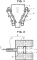
- Fig. 1 is a schematic plan view showing a film, clips, and clip rails in a tenter apparatus in a typical film production apparatus.
- the tenter apparatus in Fig. 1 has a plurality of clip devices 2 conveyed on a chain (not shown in the diagram) driven by two sprockets 1 located at both ends.
- the edges at both width-directional ends of the film 3 are griped by clips (shown in Fig. 2 ) mounted in clip devices 2 that travel on each clip rail 4, and the film 3 gripped by the clips is conveyed in the length direction (arrow direction) in the tenter apparatus as the clip devices 2 travel.
- the film 3 is stretched in the width direction as the distance between the clip rails 4 disposed both sides are increased.
- the tenter apparatus may have a preheating zone for preheating the film 3 before the stretching zone, and the stretching zone may be followed by a heat fixation zone for performing heat treatment of the film 3 and a cooling zone for cooling the heat-fixed film 3.
- the width direction is the in-plane direction in the film perpendicular to the length direction.
- Fig. 2 is the cross section along the I-I' line in Fig. 1 and shows a clip rail, bearing, and the liquid layer.
- number 5 denotes a clip that grips one of the width-directional ends of the film 3.
- the clip 5 is mounted on a linkage member 6, and the clip 5 and the linkage member 6 constitute a clip device 2.
- a plurality of bearings 7 are provided in the linkage member 6, and the plurality of bearings 7 travel on the clip rail 4 to allow the clip device 2 to travel smoothly on the clip rail 4.
- a liquid layer 8 is formed on the surface of the clip rail 4 in order to reduce the abrasion of the clip rail 4, bearings 7, etc., that can occur as the clip device 2 travels on the clip rail 4 with the clip 5 of the clip device 2 gripping the film 3.
- one clip device 2 has a total of six bearings 7 located on the left, right, top, and bottom of the clip rail 4 to hold it.
- the positions and number of the bearings 7 are not limited to the construction described above as long as the clip device 2 can travel smoothly.
- the measuring method according to the present invention can be used suitably for measuring the thickness of a liquid layer formed at a position where a plurality of members are in friction with each other.
- the liquid layer contains a metal component.
- the metal component in the liquid layer unless good effects of the invention are impaired, but it is preferably iron, stainless steel, or a compound thereof from the viewpoint of its frequent use for members such as components of bearings and rails on which bearings travel.
- the liquid layer may have an appropriately selected thickness that suites the member on which a liquid layer is to be formed, but in the case where a liquid layer is formed at a position where a plurality of members are in friction with each other, there may be a concern for excess liquid and dissipation thereof. From the viewpoint of reducing the dissipation of liquid, it is preferable for the thickness of the liquid layer to be 11 ⁇ m or less, more preferably 5 ⁇ m or less. If the thickness of the liquid layer is 11 ⁇ m or less, it serves to reduce the dissipation of components of the liquid layer that may occur as a member travels on another member on which the liquid layer is formed.
- the lower limit of the thickness of the liquid layer unless good effects of the invention are impaired, but it is about 1 ⁇ m in consideration of the detection limit of the measuring apparatus.
- a good method is to calculate the required quantity of the liquid to form a liquid layer having an intended thickness from the area of the portion where the liquid layer is to be formed, drop the liquid on the member, and spread it with a metering bar, i.e. a metal rod wound with a wire, or a brush etc.
- the quantity of liquid to be dropped may be increased in advance so that the liquid layer will reach an intended thickness during operation, or the thickness of the liquid layer may be measured periodically to allow liquid to be replenished before the liquid quantity decreases excessively.
- liquid may be spread by running the apparatus when it is difficult to spread the liquid with a brush etc.
- the thickness of the liquid layer can be adjusted easily by changing the thickness of the wire used to form the metering bar. More specifically, a decrease in the thickness of the wire leads to a decrease in the thickness of the liquid layer.
- the surface roughness of a member is 1.0 ⁇ m or more and 2.5 ⁇ m or less.
- the surface roughness of a member means a surface roughness measured by setting a vertically movable needle so that an end thereof is in contact with the surface of the member and moving it 5 mm along the surface of the member while measuring the size of its up-and-down motion.
- the surface roughness of such a member as a component of a bearing or a rail on which a bearing travels is large at the start of use and the surface becomes smooth as a result of abrasion as it is used for a long term.
- the surface roughness may become less than 1.0 ⁇ m in several years.
- the use of the method according to the present invention is advantageous because the thickness of the liquid layer can be measured easily at a time point when it is difficult to measure it by a generally known method.
- measurement accuracy improves as the surface roughness of the member decreases to 2.5 ⁇ m or less.
- the surface roughness of the member it is preferable for the surface roughness of the member to be 1.0 ⁇ m or more and 2.0 ⁇ m or less.
- the curve fitting technique is a method to calculate (determine) the thickness of a film by fitting a measured reflectance spectrum to a theoretical reflectance spectrum that is developed based on calculations according to a film structure recipe (measuring environment, refractive index (n) of the liquid layer, base material used to form the liquid layer, and expected film thickness) set up in advance.
- the spectral interference method is a measuring method designed to apply light to a film and determine the film thickness from the degree of interference of reflected light. Examples of a measuring apparatus intended for analysis by the spectral interference method using the curve fitting technique include the noncontact type spectroscopic film thickness measuring system manufactured by Filmetrics (F20 series).
- a reflectance spectrum as referred to herein is a spectrum graph in which the horizontal axis represents wavelength (nm) while the longitudinal axis represents reflectance (%).
- reflectance spectra vary with film thickness, material type and refractive index of the substance under measurement, material type and surface roughness of the base material, etc.
- the wave number in a reflectance spectrum tends to increase with an increasing film thickness, and the reflectance of a film tends to increase with an increasing refractive index.
- an appropriate range of measuring wavelengths may be set to suit the components, film thickness, etc. of the liquid layer under measurement, but it is preferably 190 nm or more and 1,700 nm or less. More specifically, in the case of a thin film, it is preferable to include a low wavelength part of the aforementioned range, whereas in the case of a thick film, the inclusion of a high wavelength part of the aforementioned range ensures an improved measurement accuracy.
- Preferable examples of light sources to emit light beams of these wavelengths include deuterium lamps for low wavelength ranges of less than 380 nm and halogen lamps for wavelength ranges of 380 nm or more, which may be used in combination to cover all of the aforementioned measuring wavelength ranges.
- the thickness of the liquid layer can be assumed to be in the aforementioned preferable range (1 ⁇ m or more and 11 ⁇ m or less), it is preferable for the measuring method according to the present invention to cover a measuring wavelength range of 380 nm or more and 1,050 nm or less.
- a measuring wavelength range is set with a lower limit of 380 nm, it is not necessary to use a deuterium lamp, which serves to reduce the measurement cost, whereas a measuring wavelength range is set with an upper limit of 1,050 nm, the thickness of the liquid layer in the aforementioned range can be measured with a sufficiently high accuracy.
- other methods for measuring the thickness of a liquid layer include a method in which laser beams are applied to an oil film to determine the thickness from the optical path difference (laser method), a spectral interference method that uses fast Fourier transformation (FFT method), and an image analysis method in which a plurality of light beams having different wavelengths are applied to a liquid layer to determine a plurality of film thickness distributions from the brightness values of the reflected light beams, although they all have difficulty in measurement of thin liquid layers.
- laser method laser method
- FFT method fast Fourier transformation
- image analysis method in which a plurality of light beams having different wavelengths are applied to a liquid layer to determine a plurality of film thickness distributions from the brightness values of the reflected light beams, although they all have difficulty in measurement of thin liquid layers.
- Fig. 3 gives an example of the thickness measuring apparatus for a liquid layer 12 that is designed for measuring the thickness of the liquid layer 12 located on the surface of a member 11.
- the number 13 denotes the main unit of an analysis apparatus that includes at least a light source (not shown) and a spectrometer (not shown), and the number 14 denotes a sensor that includes at least the end of an optical fiber for emitting and detecting a light beam and a lens for adjusting the light exposure area (not shown).
- a light beam is supplied through an optical fiber 15 connected to the light source contained in the analysis apparatus main unit 13 and adjusted to an exposure area by the lens contained in the sensor 14, thereby providing an exposure light beam 16 that is emitted toward the liquid layer 12 located on the surface of the member 11.
- the light source contained in the analysis apparatus main unit 13, optical fiber 15 connected to the light source, lens contained in the sensor 14, and exposure light beam 16 construct a light exposure means 17 for the present invention.
- the reflected light beam 18 from the surface of the liquid layer 12 and the reflected light beam 19 from the surface of the member 11 are received and condensed by the sensor 14 and then sent through the optical fiber 20 to the spectrometer contained in the analysis apparatus main unit 13.
- these parts, including the reflected light beams 18 and 19, construct a reflected light detection means 21 for the present invention.
- the analysis apparatus main unit 13 is connected to a computer 22 that contains analysis software designed for the present invention, and the combination of the analysis apparatus main unit 13 and the computer 22 works to develop a reflectance spectrum based on the reflected light beam detected by the reflected light beam detection means 21.
- the measured reflectance spectrum is compared, by the curve fitting technique, with a plurality of theoretical reflectance spectra corresponding to different theoretical liquid layer thicknesses set up in advance, thereby making it possible to identify the theoretical reflectance spectrum that most closely approximates the measured reflectance spectrum and decide on the theoretical liquid layer thickness corresponding thereto as measured liquid layer thickness.
- the analysis apparatus main unit 13 and the computer 22, including the built-in analysis software construct an analysis means 23 for the present invention.
- the measuring method that uses a liquid layer thickness measuring apparatus having such a structure will be described later.
- the measuring apparatus is designed to apply a light beam to a liquid layer located on the surface of a member, detect the reflected light by a sensor, and analyze the reflected light beam by the spectral interference method using the curve fitting technique to determine the thickness of the liquid layer.
- the film production method according to the present invention is a film production method including a step for stretching a film using a tenter apparatus having a mechanism containing bearings traveling on rails and is characterized in that a liquid layer meeting the undermentioned equation 1 is formed on the traveling path of the bearings on each rail wherein h ( ⁇ m) is the thickness of the liquid layer measured by the measuring method according to the present invention, h 1 ( ⁇ m) being the surface roughness of the rail, and h 2 ( ⁇ m) being the surface roughness of the bearings: [Formula 2] 2 h 1 2 + h 2 2 ⁇ h ⁇ 10 h 1 2 + h 2 2
- the film production method according to the present invention is a method for producing a film including a step for stretching a film using a tenter apparatus having a mechanism in which bearings travel on rails.
- a step for stretching a film using a tenter apparatus is a step in which a film is stretched at least in one direction using a tenter apparatus.
- Specific examples of known film production techniques useful for the step for stretching a film using a tenter apparatus include a sequential biaxial stretching technique in which an unstretched film is stretched in the length direction using, for example, a roller type longitudinal stretching machine, followed by stretching by the tenter apparatus in the width direction, and a simultaneous biaxial stretching technique in which an unstretched film is stretched simultaneously in the length direction and in the width direction using, for example, a tenter apparatus.
- the stretching in the length direction by a tenter apparatus is performed commonly by accelerating the clips traveling in the tenter, whereas the stretching in the width direction is performed by gradually increasing the distance between the clips gripping the edges at the width-directional ends of the film.
- h ( ⁇ m) is the thickness of the liquid layer measured by the measuring method according to the present invention
- h 1 ( ⁇ m) being the surface roughness of the rail
- h 2 ( ⁇ m) being the surface roughness of the bearings.
- the thickness h ( ⁇ m) of the liquid layer measured by the measuring method according to the present invention, the surface roughness h 1 ( ⁇ m) of the rail, and the surface roughness h 2 ( ⁇ m) of the bearings will be occasionally referred to simply as h, h 1 , and h 2 , respectively.
- both h and h 1 are measured at a position (hereinafter occasionally referred to as measuring point) on the rail 30 cm away in the opposite direction to the traveling direction of the bearings from the liquid feeding point. It is noted that in the case where there are a plurality of liquid feeding points on the rail, measurements are taken at all positions corresponding to the measuring points and all measurements taken are averaged to represent h and h 1 . For h 2 , furthermore, measurements are taken from the bearing of an appropriately selected clip device and the bearings of the two clip devices located on both sides thereof, and the measurements taken are averaged to represent h 2 . The aforementioned method can be used for measurement of both h 1 and h 2 .
- the traveling path of the bearings on each rail means the part of the rail on which the bearings travel when the tenter apparatus is in operation. Specifically, it is the part of the rail that comes in contact with the bearings when the tenter apparatus is operated without a liquid layer.
- the value of h is equal to or higher than the lower limit represented by the equation 1, it serves to reduce the abrasion of the bearings and rail and the resulting dissipation of metal in a powdery form.
- the value of h is equal to or lower than the upper limit represented by the equation 1, it serves to reduce the dissipation of the components of the liquid layer.
- the value of h is in the range represented by the equation 1, it serves to reduce the dissipation of metal powder and the components of the liquid layer, thereby preventing a deterioration in film quality and a decrease in the defective generation rate.
- Preheating, stretching, heat treatment, cooling, etc., of the film are performed in the tenter apparatus as described later, but the ambient temperature and the strength of air blown at the film differ among them.
- the traveling speed and acceleration of the clip devices containing bearings may be adjusted to control the extension ratio. In general, with an increasing strength of the air blow hitting the film and with an increasing traveling speed and acceleration of each clip device containing a bearing, the liquid components of the liquid layer on the rail will dissipate more rapidly, leading to more rapid dissipation of metal powder that is cause by abrasion of the bearings and rails.
- the thickness h ( ⁇ m) of the liquid layer is controlled in the range specified by the equation 1 by adjusting the rate of liquid feeding to the traveling path of the bearings.
- Such an embodiment allows easy production of films to be maintained for a long term under conditions where dissipation of metal powder and liquid layer components is suppressed.
- a good method is to measure the thickness h ( ⁇ m) of the liquid layer periodically by the measuring method according to the present invention and control the liquid supply rate appropriately on the basis of the measurements.
- polyester resin is melted and extruded through a nozzle having a slit-like discharge opening to form a sheet, which is then cooled on a cooling roll to provide an unstretched polyester film.
- this unstretched polyester film is heated to a temperature equal to or higher than the glass transition temperature of the polyester resin by several temperature-controlled rolls, infrared ray heaters, etc., and stretched in the length direction by a series of rolls having different circumferential speeds.
- the extension ratio in this step unless good effects of the invention are impaired, but it is preferably 2 to 8.
- the stretching in the length direction may be carried out in a single stage or may be carried out stepwise in two or more stages.
- the uniaxially stretched polyester film thus obtained is then heated (preheat) again by a tenter apparatus up to or above the glass transition temperature of the polyester resin and stretched in the width direction by clip devices containing bearings that travel on rails that gradually diverge from each other.
- a tenter apparatus up to or above the glass transition temperature of the polyester resin and stretched in the width direction by clip devices containing bearings that travel on rails that gradually diverge from each other.
- the polyester resin is polyethylene terephthalate (hereinafter occasionally referred to as PET), it is preferably 2 to 5.
- the biaxially stretched polyester film is continued to be heat-treated in the tenter apparatus.
- the polyester resin is PET
- heat treatment can be performed at a relatively high temperature of 180°C to 250°C.
- Such heat treatment serves to improve the dimensional stability of the film in the subsequent processing steps or during use as final product at high temperatures.
- dimensional stability can be further improved by relaxing the heat-treated polyester film by 1% to 10% in the length direction and/or width direction.
- a liquid layer meeting the equation 1 is formed on the traveling path of the bearings on each rail wherein h ( ⁇ m) is the thickness of the liquid layer measured by the measuring method according to the present invention, h 1 ( ⁇ m) being the surface roughness of the rail, and h 2 ( ⁇ m) being the surface roughness of the bearings.
- h ( ⁇ m) is the thickness of the liquid layer measured by the measuring method according to the present invention
- h 1 ( ⁇ m) being the surface roughness of the rail
- h 2 ( ⁇ m) being the surface roughness of the bearings.
- the heat-treated biaxially stretched polyester film is then cooled in the tenter apparatus and in the subsequent conveyance step and wound up once as an intermediate roll on a broad winder, followed by cutting by a slitter to required width and length to provide a final product.
- Each metering bar was produced by winding a wire around a metal rod.
- the thickness of the liquid layer formed by metering bar was adjusted by selecting a wire having an appropriate thickness.
- the theoretical thickness value of a liquid layer formed by metering bar will be occasionally referred to simply as the theoretical value.
- each member was cleaned to remove metal powder etc. and a liquid was dropped on the surface of the member. Then, a metering bar, i.e. a metal rod having a wire wound around it, was pressed against a rail and the liquid was spread to form a liquid layer over the surface of the member.
- a metering bar i.e. a metal rod having a wire wound around it
- Measurement was performed by the following procedure using a noncontact type spectroscopic film thickness measuring system (F20, manufactured by Filmetrics).
- F20 noncontact type spectroscopic film thickness measuring system
- Eight film structure recipes that differ only in expected film thickness were set up as described below and a theoretical reflectance spectrum was developed for each of them by the computing function contained in the apparatus (hereinafter, a reflectance spectrum developed in this way will be occasionally referred to as a theoretical reflectance spectrum).
- a light beam was applied to the liquid layer and the reflected light beam was detected by a portable type sensor to obtain a reflectance spectrum (hereinafter, a reflectance spectrum obtain in this way will be occasionally referred to as a measured reflectance spectrum).
- each theoretical reflectance spectrum and the measured reflectance spectrum were displayed on the screen of a computer and the measured reflectance spectrum and each theoretical reflectance spectrum were compared by the curve fitting technique to identify the theoretical reflectance spectrum that approximates the measured reflectance spectrum most closely.
- a film thickness expected from the identified theoretical reflectance spectrum was adopted as the thickness of the liquid layer under measurement.
- the measuring conditions used above were as described below. It is noted that three measurements were taken in each Example and Comparative example and their average was adopted as measured thickness of the liquid layer (if no measurement was obtained in three measuring runs, it was judged to be "not measurable").
- Base material used to form the liquid layer (Layer, Substrate): stainless steel
- Any film thickness value can be set in the ranges of 2 ⁇ m ⁇ 50%, 3 ⁇ m ⁇ 50%, 4 ⁇ m ⁇ 50%, 5 ⁇ m ⁇ 50%, 6 ⁇ m ⁇ 50%, 8 ⁇ m ⁇ 50%, 10 ⁇ m ⁇ 50%, and 11 ⁇ m ⁇ 50%.
- eight expected film thicknesses of 2 ⁇ m, 3 ⁇ m, 4 ⁇ m, 5 ⁇ m, 6 ⁇ m, 8 ⁇ m, 10 ⁇ m, and 11 ⁇ m were set up in film structure recipes, and a theoretical reflectance spectrum was developed to represent each of the film thicknesses.
- a light beam was applied to a liquid layer and the reflected light was detected by a portable type sensor, followed by analyzing the reflected light beam by the spectral interference method using the FFT technique.
- the measuring instrument and measuring conditions used were as described below. It is noted that three measurements were taken in each Comparative example and their average was adopted as measured thickness of the liquid layer (if no measurement was obtained in three measuring runs, it was judged to be "not measurable").
- Measuring instrument spectral interference displacement type multilayer film thickness measuring instrument (SI-T80, manufactured by Keyence Corporation)
- Measuring instrument surface profile measuring device, SP700-500 (manufactured by Toray Engineering Co., Ltd.)
- a piece of nonwoven fabric was attached at the outlet of the tenter apparatus in such a manner that it came in contact with the surface of the traveling film, and the nonwoven fabric was visually observed in 8 hours after the start of production.
- Existence/absence of dissipation of metal powder was evaluated according to the criteria given below, and only the films rated as A were judged to be acceptable.
- a 100 m portion of the film was wound off from the resulting final roll product and cut off for use as sample.
- the resulting sample was visually observed under a fluorescent lamp and existence/absence of dissipation of liquid layer components was evaluated according to the criteria given below.
- the evaluation was performed on the final product obtained in 2 hours after the start of production, and only the samples rated as A were judged to be acceptable.
- each member was cleaned in advance to remove metal powder etc. and the liquid A was dropped on the surface of the member A. Then, the metering bar was pressed and the liquid was spread to form a liquid layer over the surface of the member. Subsequently, its thickness was measured according to the method described in "(2-A) Spectral interference method using curve fitting technique” in “(2) Thickness of liquid layer”, and the measurement accuracy was evaluated according to the method described in "(3) Measurement accuracy”. Evaluation results are given in Table 1.
- a liquid layer was formed as in Example 2, and its thickness was measured according to the method described in “(2-C) Image processing method” in “(2) Thickness of liquid layer", but it was impossible to obtain measurements (Table 1).
- Example 1 A liquid layer was formed as in Example 10, and its thickness was measured according to the method described in "(2-C) Image processing method” in "(2) Thickness of liquid layer", but it was impossible to obtain measurements (Table 1).
- Table 1 Member Liquid Metering bar Theoretical liquid layer thickness ( ⁇ m) Measuremen t ( ⁇ m) Measuring method Measurement accuracy
- Example 1 A A A 2.0 2.4 curve fitting A
- Example 2 A A B 4.0 4.4 curve fitting A
- Example 3 A C 11.0 10.6 curve fitting A
- Example 4 A B A 2.0 2.6 curve fitting A
- Example 5 A B B 4.0 4.0 curve fitting A
- Example 6 A B C 11.0 11.4 curve fitting A
- Example 7 A C A 2.0 2.5 curve fitting A
- Example 8 A C B 4.0 4.1 curve fitting A
- Example 9 A C C 11.0 10.4 curve fitting A
- Example 10 B A B 4.0 4.2 curve fitting A Comparative example 1 A A B 4.0 not measurable image processing B Comparative example 2 B A B 4.0 not measurable image processing
- the Comparative examples include not only one in which the measuring method according to the present invention was not used to measure the thickness of the liquid layer on the clip rails in the tenter apparatus (Comparative example 3), but also others in which the thickness of the liquid layer measured by the measuring method according to the present invention was outside the range specified by the undermentioned equation 1 (Comparative examples 4 and 5).
- PET pellets were sufficiently vacuum-dried first, fed to an extruder, melted at 270°C to 300°C, and then extruded through a T-die to form a sheet.
- the extruded sheet was allowed to wind around a casting drum having a surface temperature of 20°C to 25°C by means of electrostatic casting so that it was cooled and solidified to provide an unstretched film.
- this unstretched film was heated up to 80°C to 100°C and stretched by two times in the length direction to provide a uniaxially stretched film.
- this uniaxial stretched film with the width-directional ends held by clips traveling on clip rails, is introduced into the preheating zone of the tenter apparatus (ambient temperature 120°C to 130°C).
- the film was stretched by three times in the width direction in a stretching zone at 140°C, heat-treated in a heat treatment zone at 230°C, and cooled to 40°C to 50°C to provide a biaxially stretched film having a thickness of 188 ⁇ m.
- the resulting biaxially stretched film was wound up once as an intermediate roll, and then the film was wound off from the intermediate roll, cut by a slitter, and wound up again to provide a film roll having a width of 100 cm.
- the thickness of the liquid layer on the clip rails in the tenter apparatus was measured by the method described in "(2-A) Spectral interference method using curve fitting technique” (Example 11) or by the method described in “(2-B) Spectral interference method using FFT technique” (Comparative example 3) in "(2) Thickness of liquid layer".
- the member A was used as clip rails and the liquid A was used as liquid for forming the film.
- the supply rate of the liquid was controlled so that the thickness of the liquid layer was 5 ⁇ m.
- Each of the clip rails had one liquid feeding point where the liquid was supplied to the clip rail and the thickness of the liquid layer was measured at a position 30 cm away in the opposite direction to the traveling direction of the bearings from the liquid feeding point.
- Example 11 The measurement in Example 11 was 5 ⁇ m (confirming that the liquid layer had a desired thickness), whereas in Comparative example 3, no measurements were obtained in three measuring runs (Table 2).
- Table 2 Member Liquid Measured liquid layer thickness ( ⁇ m) Measuring method
- Example 11 A A 5 curve fitting Comparative example 3 A A not measurable FFT
- the present invention can provide a measuring method and a measuring apparatus for measuring quantitatively and very accurately the thickness of a liquid layer formed on members of various shapes.
- generation of defectives due to dissipation of oil and metal powder can be reduced if film production is performed while controlling the thickness of the liquid layer on the clip rails in the tenter apparatus on the basis of measurements taken by using the measuring method and the measuring apparatus according to the present invention.
Landscapes
- Physics & Mathematics (AREA)
- General Physics & Mathematics (AREA)
- Engineering & Computer Science (AREA)
- Mechanical Engineering (AREA)
- Length Measuring Devices By Optical Means (AREA)
- Shaping By String And By Release Of Stress In Plastics And The Like (AREA)
- Investigating Or Analysing Materials By Optical Means (AREA)
Abstract
Description
- The present invention relates to a measuring method and a measuring apparatus for measuring quantitatively and very accurately the thickness of a liquid layer formed on the surface of a member, and also relates to a film production method that can reduce the dissipation of oil and generation of foreign objects in a tenter apparatus.
- For apparatuses that have a mechanism containing a plurality of members in contact with each other, it is a common practice to form a liquid layer (oil film in particular) between members in order to reduce the abrasion of the members during operation. If the thickness of the liquid layer is too small in such an instance, it will fail to work effectively in reducing the abrasion of the members, leading to acceleration of the damage to the apparatus and deterioration in its durability. If on the contrary, the thickness of the liquid layer is too large, the liquid will fly around the members during operation of the apparatus, and if it is a manufacturing apparatus to produce articles, the liquid will adhere to the products, possibly deteriorating their quality. When using such an apparatus, therefore, it is important to measure the thickness of the liquid layer between members in contact with each other to confirm that it is an appropriate range, and there have been many studies aiming to develop methods for measuring the thickness of liquid layers.
- Known methods proposed to measure the thickness of a liquid layer between members include, for example, a method in which an oil film is formed between a glass ball and a race groove of a race ring provided below the glass ball and irradiated with a light beam, and the thickness of the oil film is determined based on the interference of reflected light (Patent document 1) and a method using interference of light in which the film pressure distribution of a lubricant that lubricates contact portions between objects in an elastohydrodynamic lubrication state (EHL state) is determined based on the brightness of reflected light (Patent document 2).
-
- Patent document 1: Japanese Unexamined Patent Publication (Kokai) No.
2014-25885 - Patent document 2: Japanese Unexamined Patent Publication (Kokai) No.
2017-44587 - The technique described in
Patent document 1, however, is useful only for measurement of an oil film thickness between a spherical member, such as rolling bearing, and a member having a track groove to accept it, but cannot be applied to measurement of an oil film thickness between members of other shapes. The technique described inPatent document 2, furthermore, is low in measuring accuracy in the case where the member does not have a very smooth surface, and therefore, can be applied only to limited uses and member shapes. - Thus, an object of the present invention is to solve the above problems with the conventional technology in order to provide a measuring method and a measuring apparatus for measuring quantitatively and very accurately the thickness of a liquid layer formed on members of various shapes and to provide a film production method that uses the measuring method.
- The present invention adopts the following constitution to solve the problems described above.
- (1) A method for measuring the thickness of a liquid layer including applying a light beam to a liquid layer disposed on the surface of a member, detecting the reflected light by a sensor, and analyzing the reflected light according to a spectral interference method using the curve fitting technique to determine the thickness of the liquid layer.
- (2) A method for measuring the thickness of a liquid layer as described in (1), wherein the liquid layer contains a metal component.
- (3) A method for measuring the thickness of a liquid layer as described in either (1) or (2), wherein the liquid layer has a thickness of 11 µm or less.
- (4) A method for measuring the thickness of a liquid layer as described in any one of (1) to (3), wherein the member has a surface roughness of 1.0 µm or more and 2.5 µm or less.
- (5) A method for measuring the thickness of a liquid layer as described in any one of (1) to (4), wherein the member is a rail on which bearings travel.
- (6) A method for measuring the thickness of a liquid layer as described in (5), wherein the rail is a clip rail of a tenter apparatus on which clip devices travel.
- (7) A method for measuring the thickness of a liquid layer as described in any one of (1) to (6), wherein the sensor is a portable type sensor.
- (8) An apparatus for measuring the thickness of a liquid layer by a measuring method as described in any one of (1) to (7) including at least a light exposure means for emitting light toward a liquid layer disposed on the surface of a member, a reflected light detection means for detecting the reflected light coming from the surface of the member and the surface of the liquid layer, an analysis means for measuring the reflectance spectrum based on the detected reflected light, comparing, by the curve fitting technique, the measured reflectance spectrum with a plurality of theoretical reflectance spectra corresponding to different theoretical liquid layer thicknesses set up in advance, identifying the theoretical reflectance spectrum that most closely approximates the measured reflectance spectrum, and deciding on the theoretical liquid layer thickness corresponding thereto as measured liquid layer thickness.
- (9) A film production method including a step for stretching a film using a tenter apparatus having a mechanism in which bearings travel on rails and
- The present invention can provide a measuring method and a measuring apparatus for measuring quantitatively and very accurately the thickness of a liquid layer formed on members of various shapes. In addition, generation of defectives due to dissipation of oil and metal powder can be reduced if film production is performed while controlling the thickness of the liquid layer on the clip rails in the tenter apparatus on the basis of measurements taken by using the measuring method and the measuring apparatus according to the present invention.
-
- [
Fig. 1 ] This is a schematic plan view showing a film, clip devices, and clip rails in a tenter apparatus in a typical film production apparatus. - [
Fig. 2 ] This is an enlarged cross section along the I-I' line inFig. 1 . - [
Fig. 3 ] This is a schematic structural diagram of a typical apparatus for measuring the thickness of a liquid layer according to the present invention. - The invention is described more specifically below.
- The method for measuring the thickness of a liquid layer according to the present invention includes applying a light beam to a liquid layer disposed on the surface of a member, detecting the reflected light by a sensor, and analyzing the reflected light according to a spectral interference method using the curve fitting technique to determine the thickness of the liquid layer.
- From the viewpoint of convenience and simplicity of measuring, it is important for the measuring method according to the present invention to apply light to the liquid layer disposed on the surface of a member and detect the reflected light by a sensor. Such an embodiment serves to obtain information on the reflected light required for the undermentioned analysis by the spectral interference method using the curve fitting technique and enables the determination of the thickness of the liquid layer.
- A liquid layer as referred to herein is a film formed on a member and is in a liquid state in the operating environment of the member. Specific examples include oil film or water film staying under conditions where the oil or water are in a liquid state. The measuring method according to the present invention can serve to measure a low-transparent liquid layer, which is more difficult to measure, and therefore, the method is advantageous for measuring a thickness of oil film.
- There are no particular limitations on the sensor unless good effects of the invention are impaired, but it is preferably a portable type sensor because measurements can be taken without dismounting or moving the member that carries the liquid layer. Such an embodiment enables the measurement of a liquid layer on a member that is very heavy or large and difficult to dismount, such as the undermentioned clip rail in a tenter apparatus. A portable type sensor as referred to herein is a movable sensor that can detect light. Specific examples of portable type sensors include a built-in type one mounted in an instrument that can be moved freely and a movable one connected to an instrument through a wire etc. and can be moved freely within the range of the length of the wire etc.
- There are no particular limitations on the weight and size of the portable type sensors as long as their bodies are movable, but from the viewpoint of convenience, they are preferably light and small. It is also preferable to adopt a portable type sensor that serves both for emitting light for exposure while receiving light from a light source connected through an optical fiber cable and for detecting the reflected light. Examples of a measuring apparatus equipped with such a portable type sensor include the noncontact type spectroscopic film thickness measuring system manufactured by Filmetrics (F20 series).
- In the case of using a portable type sensor having the two functions of emitting a light beam for exposure and detecting the reflected light as described above, it is preferable that the angle between the exposure light beam and the reflected light beam is as close as possible to 0° in order to increase the accuracy in reflected light detection to ensure an improved measuring accuracy. Thus, if the surface of the member is flat, it is preferable to emit light perpendicular to the surface of the member, whereas it is curved, it is preferable to emit light perpendicular to the plane tangent to the measuring point.
- The incident light used for exposure for the measurement may have an appropriately selected frequency to suit the components of the liquid layer unless good effects of the invention are impaired. In the case of a liquid layer containing oil as primary component, for example, it is preferably in the range of 0 Hz to 1, 000 Hz from the viewpoint of precision of analysis.
- There are no particular limitations on the member as long as a liquid layer can be formed on the surface thereof, but it is preferable that there are two or more members that are in friction with each other from the viewpoint of forming a liquid layer such as oil film commonly at a position where a plurality of members are in friction with each other and require reduction in abrasion. Such members include, for example, components of bearings and rails on which bearings travel.
- There are no particular limitations on the rail unless good effects of the invention are impaired, but it is preferably a clip rail in a tenter apparatus. Commonly, a tenter apparatus is used for stretching a film. In this instance, the thickness of the liquid layer on the clip rail in a tenter apparatus has to be maintained at a constant in order to prevent the quality of the film from being deteriorated by dissipation of powder and dissipation of components of the liquid layer attributed to abrasion of the member. Since the measuring method according to the present invention can measure quantitatively and very accurately the thickness of a liquid layer, a film having a higher quality can be produced by controlling the thickness of the liquid layer on the clip rail in the tenter apparatus based on measurements taken by this method.
- Next, the mechanism for stretching a film using a tenter apparatus is described in detail below with reference to drawings.
Fig. 1 is a schematic plan view showing a film, clips, and clip rails in a tenter apparatus in a typical film production apparatus. The tenter apparatus inFig. 1 has a plurality ofclip devices 2 conveyed on a chain (not shown in the diagram) driven by twosprockets 1 located at both ends. In the tenter apparatus, the edges at both width-directional ends of thefilm 3 are griped by clips (shown inFig. 2 ) mounted inclip devices 2 that travel on eachclip rail 4, and thefilm 3 gripped by the clips is conveyed in the length direction (arrow direction) in the tenter apparatus as theclip devices 2 travel. In this instance, thefilm 3 is stretched in the width direction as the distance between theclip rails 4 disposed both sides are increased. Here, although not shown inFig. 1 , the tenter apparatus may have a preheating zone for preheating thefilm 3 before the stretching zone, and the stretching zone may be followed by a heat fixation zone for performing heat treatment of thefilm 3 and a cooling zone for cooling the heat-fixedfilm 3. It is noted that the width direction is the in-plane direction in the film perpendicular to the length direction. - Next, the liquid layer located between a
clip rail 4 and aclip device 2 in the tenter apparatus is described in detail below with reference toFig. 2. Fig. 2 is the cross section along the I-I' line inFig. 1 and shows a clip rail, bearing, and the liquid layer. InFig. 2 ,number 5 denotes a clip that grips one of the width-directional ends of thefilm 3. Theclip 5 is mounted on alinkage member 6, and theclip 5 and thelinkage member 6 constitute aclip device 2. A plurality ofbearings 7 are provided in thelinkage member 6, and the plurality ofbearings 7 travel on theclip rail 4 to allow theclip device 2 to travel smoothly on theclip rail 4. Then, aliquid layer 8 is formed on the surface of theclip rail 4 in order to reduce the abrasion of theclip rail 4,bearings 7, etc., that can occur as theclip device 2 travels on theclip rail 4 with theclip 5 of theclip device 2 gripping thefilm 3. Here, in the example given inFig. 2 , oneclip device 2 has a total of sixbearings 7 located on the left, right, top, and bottom of theclip rail 4 to hold it. The positions and number of thebearings 7 are not limited to the construction described above as long as theclip device 2 can travel smoothly. - As described above, the measuring method according to the present invention can be used suitably for measuring the thickness of a liquid layer formed at a position where a plurality of members are in friction with each other. In this case, the liquid layer contains a metal component. There are no particular limitations on the metal component in the liquid layer unless good effects of the invention are impaired, but it is preferably iron, stainless steel, or a compound thereof from the viewpoint of its frequent use for members such as components of bearings and rails on which bearings travel.
- The liquid layer may have an appropriately selected thickness that suites the member on which a liquid layer is to be formed, but in the case where a liquid layer is formed at a position where a plurality of members are in friction with each other, there may be a concern for excess liquid and dissipation thereof. From the viewpoint of reducing the dissipation of liquid, it is preferable for the thickness of the liquid layer to be 11 µm or less, more preferably 5 µm or less. If the thickness of the liquid layer is 11 µm or less, it serves to reduce the dissipation of components of the liquid layer that may occur as a member travels on another member on which the liquid layer is formed. Here, there are no particular limitations on the lower limit of the thickness of the liquid layer unless good effects of the invention are impaired, but it is about 1 µm in consideration of the detection limit of the measuring apparatus.
- There are no particular limitations on the method to be used to form a liquid layer having a thickness of 11 µm or less or in the aforementioned preferable range unless good effects of the invention are impaired, but for example, a good method is to calculate the required quantity of the liquid to form a liquid layer having an intended thickness from the area of the portion where the liquid layer is to be formed, drop the liquid on the member, and spread it with a metering bar, i.e. a metal rod wound with a wire, or a brush etc. Here, in the case where there is a concern for evaporation of a component of the liquid layer as the member is exposed to a high temperature during operation, the quantity of liquid to be dropped may be increased in advance so that the liquid layer will reach an intended thickness during operation, or the thickness of the liquid layer may be measured periodically to allow liquid to be replenished before the liquid quantity decreases excessively. In the case where liquid is to be replenished during operation, liquid may be spread by running the apparatus when it is difficult to spread the liquid with a brush etc.
- In the case where a liquid layer is to be formed using a metering bar, i.e. a metal rod wound with a wire, the thickness of the liquid layer can be adjusted easily by changing the thickness of the wire used to form the metering bar. More specifically, a decrease in the thickness of the wire leads to a decrease in the thickness of the liquid layer.
- For the measuring method according to the present invention, it is preferable for the surface roughness of a member to be 1.0 µm or more and 2.5 µm or less. Here, the surface roughness of a member means a surface roughness measured by setting a vertically movable needle so that an end thereof is in contact with the surface of the member and moving it 5 mm along the surface of the member while measuring the size of its up-and-down motion.
- In general, the surface roughness of such a member as a component of a bearing or a rail on which a bearing travels is large at the start of use and the surface becomes smooth as a result of abrasion as it is used for a long term. The surface roughness may become less than 1.0 µm in several years. For a member having a surface roughness of 1.0 µm or more, it may be difficult to measure the thickness of the liquid layer on its surface by a generally known method (for example, the method described in Patent document 2). Specifically, for a member having a surface roughness of 1.0 µm or more, the use of the method according to the present invention is advantageous because the thickness of the liquid layer can be measured easily at a time point when it is difficult to measure it by a generally known method. On the other hand, measurement accuracy improves as the surface roughness of the member decreases to 2.5 µm or less. From the viewpoint described above, it is preferable for the surface roughness of the member to be 1.0 µm or more and 2.0 µm or less.
- For the measuring method according to the present invention, it is important, from the viewpoint of measuring the thickness of a thin liquid layer very accurately and quantitatively, that the thickness of the liquid layer is determined based on analysis of the reflected light according to a spectral interference method using the curve fitting technique. Here, the curve fitting technique is a method to calculate (determine) the thickness of a film by fitting a measured reflectance spectrum to a theoretical reflectance spectrum that is developed based on calculations according to a film structure recipe (measuring environment, refractive index (n) of the liquid layer, base material used to form the liquid layer, and expected film thickness) set up in advance. More specifically, a plurality of theoretical reflectance spectra are prepared in advance based on calculations according to a plurality of film structure recipes that differ only in expected film thickness, and the theoretical reflectance spectrum that approximates the measured reflectance spectrum most closely is identified. Then, the expected film thickness used in this theoretical reflectance spectrum is adopted as the thickness of the film under measurement. In this instance, the measuring range can be increased by setting a wider range of expected film thickness in film structure recipes, whereas the measurement accuracy can be enhanced by decreasing the increments in expected film thickness in film structure recipes. Furthermore, the spectral interference method is a measuring method designed to apply light to a film and determine the film thickness from the degree of interference of reflected light. Examples of a measuring apparatus intended for analysis by the spectral interference method using the curve fitting technique include the noncontact type spectroscopic film thickness measuring system manufactured by Filmetrics (F20 series).
- A reflectance spectrum as referred to herein is a spectrum graph in which the horizontal axis represents wavelength (nm) while the longitudinal axis represents reflectance (%). In general, reflectance spectra vary with film thickness, material type and refractive index of the substance under measurement, material type and surface roughness of the base material, etc. For example, the wave number in a reflectance spectrum tends to increase with an increasing film thickness, and the reflectance of a film tends to increase with an increasing refractive index.
- For the measuring method according to the present invention, an appropriate range of measuring wavelengths may be set to suit the components, film thickness, etc. of the liquid layer under measurement, but it is preferably 190 nm or more and 1,700 nm or less. More specifically, in the case of a thin film, it is preferable to include a low wavelength part of the aforementioned range, whereas in the case of a thick film, the inclusion of a high wavelength part of the aforementioned range ensures an improved measurement accuracy. Preferable examples of light sources to emit light beams of these wavelengths include deuterium lamps for low wavelength ranges of less than 380 nm and halogen lamps for wavelength ranges of 380 nm or more, which may be used in combination to cover all of the aforementioned measuring wavelength ranges.
- In the case where the thickness of the liquid layer can be assumed to be in the aforementioned preferable range (1 µm or more and 11 µm or less), it is preferable for the measuring method according to the present invention to cover a measuring wavelength range of 380 nm or more and 1,050 nm or less. When a measuring wavelength range is set with a lower limit of 380 nm, it is not necessary to use a deuterium lamp, which serves to reduce the measurement cost, whereas a measuring wavelength range is set with an upper limit of 1,050 nm, the thickness of the liquid layer in the aforementioned range can be measured with a sufficiently high accuracy.
- In addition to the spectral interference method that uses the curve fitting technique, other methods for measuring the thickness of a liquid layer include a method in which laser beams are applied to an oil film to determine the thickness from the optical path difference (laser method), a spectral interference method that uses fast Fourier transformation (FFT method), and an image analysis method in which a plurality of light beams having different wavelengths are applied to a liquid layer to determine a plurality of film thickness distributions from the brightness values of the reflected light beams, although they all have difficulty in measurement of thin liquid layers.
- Next, described below with reference to
Fig. 3 is an example of the liquid layer thickness measuring apparatus according to the present invention that is designed for measuring the thickness of a liquid layer by the aforementioned measuring method according to the present invention.Fig. 3 gives an example of the thickness measuring apparatus for aliquid layer 12 that is designed for measuring the thickness of theliquid layer 12 located on the surface of amember 11. Thenumber 13 denotes the main unit of an analysis apparatus that includes at least a light source (not shown) and a spectrometer (not shown), and thenumber 14 denotes a sensor that includes at least the end of an optical fiber for emitting and detecting a light beam and a lens for adjusting the light exposure area (not shown). A light beam is supplied through anoptical fiber 15 connected to the light source contained in the analysis apparatusmain unit 13 and adjusted to an exposure area by the lens contained in thesensor 14, thereby providing anexposure light beam 16 that is emitted toward theliquid layer 12 located on the surface of themember 11. Thus, the light source contained in the analysis apparatusmain unit 13,optical fiber 15 connected to the light source, lens contained in thesensor 14, andexposure light beam 16 construct a light exposure means 17 for the present invention. - The reflected
light beam 18 from the surface of theliquid layer 12 and the reflectedlight beam 19 from the surface of themember 11 are received and condensed by thesensor 14 and then sent through theoptical fiber 20 to the spectrometer contained in the analysis apparatusmain unit 13. Thus, these parts, including the reflected light beams 18 and 19, construct a reflected light detection means 21 for the present invention. - The analysis apparatus
main unit 13 is connected to acomputer 22 that contains analysis software designed for the present invention, and the combination of the analysis apparatusmain unit 13 and thecomputer 22 works to develop a reflectance spectrum based on the reflected light beam detected by the reflected light beam detection means 21. The measured reflectance spectrum is compared, by the curve fitting technique, with a plurality of theoretical reflectance spectra corresponding to different theoretical liquid layer thicknesses set up in advance, thereby making it possible to identify the theoretical reflectance spectrum that most closely approximates the measured reflectance spectrum and decide on the theoretical liquid layer thickness corresponding thereto as measured liquid layer thickness. Thus, the analysis apparatusmain unit 13 and thecomputer 22, including the built-in analysis software, construct an analysis means 23 for the present invention. The measuring method that uses a liquid layer thickness measuring apparatus having such a structure will be described later. - Thus, the measuring apparatus according to the present invention is designed to apply a light beam to a liquid layer located on the surface of a member, detect the reflected light by a sensor, and analyze the reflected light beam by the spectral interference method using the curve fitting technique to determine the thickness of the liquid layer.
- Next, the film production method according to the present invention is described below. The film production method according to the present invention is a film production method including a step for stretching a film using a tenter apparatus having a mechanism containing bearings traveling on rails and is characterized in that a liquid layer meeting the
undermentioned equation 1 is formed on the traveling path of the bearings on each rail wherein h (µm) is the thickness of the liquid layer measured by the measuring method according to the present invention, h1 (µm) being the surface roughness of the rail, and h2 (µm) being the surface roughness of the bearings:
[Formula 2]
- The film production method according to the present invention is a method for producing a film including a step for stretching a film using a tenter apparatus having a mechanism in which bearings travel on rails. Here, "a step for stretching a film using a tenter apparatus" is a step in which a film is stretched at least in one direction using a tenter apparatus.
- Specific examples of known film production techniques useful for the step for stretching a film using a tenter apparatus include a sequential biaxial stretching technique in which an unstretched film is stretched in the length direction using, for example, a roller type longitudinal stretching machine, followed by stretching by the tenter apparatus in the width direction, and a simultaneous biaxial stretching technique in which an unstretched film is stretched simultaneously in the length direction and in the width direction using, for example, a tenter apparatus. The stretching in the length direction by a tenter apparatus is performed commonly by accelerating the clips traveling in the tenter, whereas the stretching in the width direction is performed by gradually increasing the distance between the clips gripping the edges at the width-directional ends of the film.
- For the film production method according to the present invention, it is important, from the viewpoint of ensuring improved film quality, that a liquid layer meeting the
equation 1 is formed on the traveling path of the bearings on each rail wherein h (µm) is the thickness of the liquid layer measured by the measuring method according to the present invention, h1 (µm) being the surface roughness of the rail, and h2 (µm) being the surface roughness of the bearings. Hereinafter, the thickness h (µm) of the liquid layer measured by the measuring method according to the present invention, the surface roughness h1 (µm) of the rail, and the surface roughness h2 (µm) of the bearings will be occasionally referred to simply as h, h1, and h2, respectively. In this instance, both h and h1 are measured at a position (hereinafter occasionally referred to as measuring point) on the rail 30 cm away in the opposite direction to the traveling direction of the bearings from the liquid feeding point. It is noted that in the case where there are a plurality of liquid feeding points on the rail, measurements are taken at all positions corresponding to the measuring points and all measurements taken are averaged to represent h and h1. For h2, furthermore, measurements are taken from the bearing of an appropriately selected clip device and the bearings of the two clip devices located on both sides thereof, and the measurements taken are averaged to represent h2. The aforementioned method can be used for measurement of both h1 and h2. - Here, the traveling path of the bearings on each rail means the part of the rail on which the bearings travel when the tenter apparatus is in operation. Specifically, it is the part of the rail that comes in contact with the bearings when the tenter apparatus is operated without a liquid layer.
- If the value of h is equal to or higher than the lower limit represented by the
equation 1, it serves to reduce the abrasion of the bearings and rail and the resulting dissipation of metal in a powdery form. On the other hand, if the value of h is equal to or lower than the upper limit represented by theequation 1, it serves to reduce the dissipation of the components of the liquid layer. Specifically, if the value of h is in the range represented by theequation 1, it serves to reduce the dissipation of metal powder and the components of the liquid layer, thereby preventing a deterioration in film quality and a decrease in the defective generation rate. - Preheating, stretching, heat treatment, cooling, etc., of the film are performed in the tenter apparatus as described later, but the ambient temperature and the strength of air blown at the film differ among them. Furthermore, the traveling speed and acceleration of the clip devices containing bearings may be adjusted to control the extension ratio. In general, with an increasing strength of the air blow hitting the film and with an increasing traveling speed and acceleration of each clip device containing a bearing, the liquid components of the liquid layer on the rail will dissipate more rapidly, leading to more rapid dissipation of metal powder that is cause by abrasion of the bearings and rails.
- It is preferable for the film production method according to the present invention to form a liquid layer that meets the
equation 2 given below in order to reduce their dissipation even under severe conditions, such as the above case, where the metal powder and components of the liquid layer can dissipate rapidly.
[Formula 3]
- For the film production method according to the present invention, it is preferable, from the viewpoint of providing a film having improved quality, that the thickness h (µm) of the liquid layer is controlled in the range specified by the
equation 1 by adjusting the rate of liquid feeding to the traveling path of the bearings. Such an embodiment allows easy production of films to be maintained for a long term under conditions where dissipation of metal powder and liquid layer components is suppressed. There are no particular limitations on the means of controlling the thickness h (µm) of the liquid layer unless good effects of the invention are impaired, but for example, a good method is to measure the thickness h (µm) of the liquid layer periodically by the measuring method according to the present invention and control the liquid supply rate appropriately on the basis of the measurements. - Next, the film production method according to the present invention is described in detail below with reference to a case where sequential biaxial stretching of polyester resin is performed. It is noted, however, that the following embodiment only exemplifies typical application of the present invention, and the invention is not limited thereto.
- First, using an extruder, polyester resin is melted and extruded through a nozzle having a slit-like discharge opening to form a sheet, which is then cooled on a cooling roll to provide an unstretched polyester film. Subsequently, this unstretched polyester film is heated to a temperature equal to or higher than the glass transition temperature of the polyester resin by several temperature-controlled rolls, infrared ray heaters, etc., and stretched in the length direction by a series of rolls having different circumferential speeds. There are no particular limitations on the extension ratio in this step unless good effects of the invention are impaired, but it is preferably 2 to 8. Here, the stretching in the length direction may be carried out in a single stage or may be carried out stepwise in two or more stages.
- The uniaxially stretched polyester film thus obtained is then heated (preheat) again by a tenter apparatus up to or above the glass transition temperature of the polyester resin and stretched in the width direction by clip devices containing bearings that travel on rails that gradually diverge from each other. There are no particular limitations on the ratio of extension in the width direction unless good effects of the invention are impaired, but in the case where the polyester resin is polyethylene terephthalate (hereinafter occasionally referred to as PET), it is preferably 2 to 5.
- After the stretching in the length direction and width direction, the biaxially stretched polyester film is continued to be heat-treated in the tenter apparatus. In the case where the polyester resin is PET, heat treatment can be performed at a relatively high temperature of 180°C to 250°C. Such heat treatment serves to improve the dimensional stability of the film in the subsequent processing steps or during use as final product at high temperatures. In addition, dimensional stability can be further improved by relaxing the heat-treated polyester film by 1% to 10% in the length direction and/or width direction.
- In the tenter apparatus, a liquid layer meeting the
equation 1, preferably a liquid layer meeting theequation 2, is formed on the traveling path of the bearings on each rail wherein h (µm) is the thickness of the liquid layer measured by the measuring method according to the present invention, h1 (µm) being the surface roughness of the rail, and h2 (µm) being the surface roughness of the bearings. If the thickness h (µm) of the liquid layer measured by the measuring method according to the present invention meets theequation 1, it serves to reduce the dissipation of metal powder caused by abrasion of the bearings and rails and reduce the dissipation of liquid layer components that occurs as the bearings travel on the rails, thus preventing deterioration in film quality from being caused by them. - The heat-treated biaxially stretched polyester film is then cooled in the tenter apparatus and in the subsequent conveyance step and wound up once as an intermediate roll on a broad winder, followed by cutting by a slitter to required width and length to provide a final product.
- The invention is described in more detail below with reference to Examples. It is noted, however, that the present invention is not limited to the Examples given below.
-
- Liquid A: mineral lubricating oil, Daphne (registered trademark) Hi-Temp Oil C (manufactured by Idemitsu Kosan Co., Ltd.)
- Liquid B: alkyl diphenyl ether oil, Moresco Hilube (registered trademark) LZ-560 (manufactured by Moresco Corporation)
- Liquid C: ester oil, Primium Fluid (registered trademark) Special (manufactured by NOK Klüber Co., Ltd.)
-
- Member A: stainless steel clip rail used for two years (surface roughness: 1.1 µm)
- Member B: unused stainless steel clip rail (surface roughness: 2.0 µm or more and 2.4 µm or less)
- Each member had a flat portion and a liquid layer was formed there.
-
- Metering bar A: designed so that a liquid layer formed by metering bar has a theoretical thickness value of 2.0 µm
- Metering bar B: designed so that a liquid layer formed by metering bar has a theoretical thickness value of 4.0 µm
- Metering bar C: designed so that a liquid layer formed by metering bar has a theoretical thickness value of 11.0 µm
- Each metering bar was produced by winding a wire around a metal rod. The thickness of the liquid layer formed by metering bar was adjusted by selecting a wire having an appropriate thickness. Hereinafter, the theoretical thickness value of a liquid layer formed by metering bar will be occasionally referred to simply as the theoretical value.
- Measurements and evaluations described in the Examples were carried out under the conditions specified below.
- The surface of each member was cleaned to remove metal powder etc. and a liquid was dropped on the surface of the member. Then, a metering bar, i.e. a metal rod having a wire wound around it, was pressed against a rail and the liquid was spread to form a liquid layer over the surface of the member.
- Measurement was performed by the following procedure using a noncontact type spectroscopic film thickness measuring system (F20, manufactured by Filmetrics). First, eight film structure recipes that differ only in expected film thickness were set up as described below and a theoretical reflectance spectrum was developed for each of them by the computing function contained in the apparatus (hereinafter, a reflectance spectrum developed in this way will be occasionally referred to as a theoretical reflectance spectrum). Then, a light beam was applied to the liquid layer and the reflected light beam was detected by a portable type sensor to obtain a reflectance spectrum (hereinafter, a reflectance spectrum obtain in this way will be occasionally referred to as a measured reflectance spectrum). Subsequently, using the analysis software described below, each theoretical reflectance spectrum and the measured reflectance spectrum were displayed on the screen of a computer and the measured reflectance spectrum and each theoretical reflectance spectrum were compared by the curve fitting technique to identify the theoretical reflectance spectrum that approximates the measured reflectance spectrum most closely. Then, a film thickness expected from the identified theoretical reflectance spectrum (theoretical liquid layer thickness corresponding to the theoretical reflectance spectrum) was adopted as the thickness of the liquid layer under measurement. The measuring conditions used above were as described below. It is noted that three measurements were taken in each Example and Comparative example and their average was adopted as measured thickness of the liquid layer (if no measurement was obtained in three measuring runs, it was judged to be "not measurable").
- Expected film thickness: Any film thickness value can be set in the ranges of 2 µm ± 50%, 3 µm ± 50%, 4 µm ± 50%, 5 µm ± 50%, 6 µm ± 50%, 8 µm ± 50%, 10 µm ± 50%, and 11 µm ± 50%. For the Examples, however, eight expected film thicknesses of 2 µm, 3 µm, 4 µm, 5 µm, 6 µm, 8 µm, 10 µm, and 11 µm were set up in film structure recipes, and a theoretical reflectance spectrum was developed to represent each of the film thicknesses. Thus, such theoretical reflectance spectra and theoretical film thicknesses corresponding to them (expected film thicknesses) were set up in advance. In the case where film thickness measurements of higher accuracy are desired, it is recommended as follows: a theoretical reflectance spectrum that approximates the measured reflectance spectrum most closely is identified in the film structure recipes, and a film thickness expected from the identified theoretical reflectance spectrum is identified, followed by developing more detailed film thickness recipes around the identified expected film thickness and performing analysis by the curve fitting technique as in the above case (for example, if the identified expected film thickness is 4 µm, the film thicknesses of 3.8, 3.9, 4.0, 4.1, 4.2, ... µm and film structure recipes for theoretical reflectance spectra corresponding to them are set up, and from among them, a theoretical reflectance spectrum that approximates the measured reflectance spectrum most closely is identified, followed by adopting the expected film thickness assumed in this identified theoretical reflectance spectrum as the thickness of the film under measurement).
-
- Measuring wavelength range: 380 nm to 1,050 nm
- Distance between sensor head and surface of member: 200 mm
- Angle between surface of member and exposure light beam: 90°
- Analysis software and mode: FIL Measure, film thickness measuring mode
- A light beam was applied to a liquid layer and the reflected light was detected by a portable type sensor, followed by analyzing the reflected light beam by the spectral interference method using the FFT technique. The measuring instrument and measuring conditions used were as described below. It is noted that three measurements were taken in each Comparative example and their average was adopted as measured thickness of the liquid layer (if no measurement was obtained in three measuring runs, it was judged to be "not measurable").
- Measuring instrument: spectral interference displacement type multilayer film thickness measuring instrument (SI-T80, manufactured by Keyence Corporation)
-
- Distance between sensor head and surface of member: 80 mm
- Angle between surface of member and exposure light beam: 90°
- Three light beams having different wavelengths were applied to a liquid layer and a plurality of film thickness distributions were estimated from the brightness values of the reflected light beams and used for determination. The measuring instrument and measuring conditions used were as described below. It is noted that three measurements were taken in each Comparative example and their average was adopted as measured thickness of the liquid layer (if no measurement was obtained in three measuring runs, it was judged to be "not measurable").
- Camera: three wavelength type multiband pass filter camera, acA640-90 uc (7.4 µm/pix, 640 x 480 pix, manufactured by Basler)
-
- Objective lens: 10x
- Field size: 0.47 x 0.36
- The measured value obtained by each method described in "(2) Thickness of liquid layer" was divided by the theoretical value described in "(1) Formation of liquid layer" and the quotient (hereinafter occasionally referred to as "measured value / theoretical value") was used for evaluation according to the criteria given below. Only the films rated as A were judged to be acceptable. Here, a "measured value / theoretical value" ratio closer to 1.0 means a higher measurement accuracy.
- A: The "measured value / theoretical value" ratio is 0.70 or more and 1.30 or less.
- B: The "measured value / theoretical value" ratio is outside the above range or the film is not measurable.
- Using a small surface roughness measuring device (product number: SJ-210, manufactured by Mitutoyo Corporation), a total of three surface roughness measurements were taken from the bearing traveling path on each member, and the average was adopted to represent the surface roughness (µm) of the member.
- A piece of nonwoven fabric was attached at the outlet of the tenter apparatus in such a manner that it came in contact with the surface of the traveling film, and the nonwoven fabric was visually observed in 8 hours after the start of production. Existence/absence of dissipation of metal powder was evaluated according to the criteria given below, and only the films rated as A were judged to be acceptable.
- A: Metal powder was not found attached on the surface of the nonwoven fabric.
- B: Metal powder was found attached on the surface of the nonwoven fabric.
- A 100 m portion of the film was wound off from the resulting final roll product and cut off for use as sample. The resulting sample was visually observed under a fluorescent lamp and existence/absence of dissipation of liquid layer components was evaluated according to the criteria given below. Here, the evaluation was performed on the final product obtained in 2 hours after the start of production, and only the samples rated as A were judged to be acceptable.
- A: Liquid layer components were not found attached.
- B: Liquid layer components were found attached.
- Examples and Comparative examples of measurements of the thickness of liquid layers are given below.
- The surface of each member was cleaned in advance to remove metal powder etc. and the liquid A was dropped on the surface of the member A. Then, the metering bar was pressed and the liquid was spread to form a liquid layer over the surface of the member. Subsequently, its thickness was measured according to the method described in "(2-A) Spectral interference method using curve fitting technique" in "(2) Thickness of liquid layer", and the measurement accuracy was evaluated according to the method described in "(3) Measurement accuracy". Evaluation results are given in Table 1.
- Except for adopting a member, liquid, metering bar, and theoretical liquid layer thickness (µm) as given in Table 1, the same procedure as in Example 1 was carried out. Results are given in Table 1.
- A liquid layer was formed as in Example 2, and its thickness was measured according to the method described in "(2-C) Image processing method" in "(2) Thickness of liquid layer", but it was impossible to obtain measurements (Table 1).
- A liquid layer was formed as in Example 10, and its thickness was measured according to the method described in "(2-C) Image processing method" in "(2) Thickness of liquid layer", but it was impossible to obtain measurements (Table 1).
[Table 1] Member Liquid Metering bar Theoretical liquid layer thickness (µm) Measuremen t (µm) Measuring method Measurement accuracy Example 1 A A A 2.0 2.4 curve fitting A Example 2 A A B 4.0 4.4 curve fitting A Example 3 A A C 11.0 10.6 curve fitting A Example 4 A B A 2.0 2.6 curve fitting A Example 5 A B B 4.0 4.0 curve fitting A Example 6 A B C 11.0 11.4 curve fitting A Example 7 A C A 2.0 2.5 curve fitting A Example 8 A C B 4.0 4.1 curve fitting A Example 9 A C C 11.0 10.4 curve fitting A Example 10 B A B 4.0 4.2 curve fitting A Comparative example 1 A A B 4.0 not measurable image processing B Comparative example 2 B A B 4.0 not measurable image processing B - The film production methods used in the Examples and Comparative examples are described below. Regarding the film production methods used here, the Comparative examples include not only one in which the measuring method according to the present invention was not used to measure the thickness of the liquid layer on the clip rails in the tenter apparatus (Comparative example 3), but also others in which the thickness of the liquid layer measured by the measuring method according to the present invention was outside the range specified by the undermentioned equation 1 (Comparative examples 4 and 5).
[Formula 4]
- PET pellets were sufficiently vacuum-dried first, fed to an extruder, melted at 270°C to 300°C, and then extruded through a T-die to form a sheet. The extruded sheet was allowed to wind around a casting drum having a surface temperature of 20°C to 25°C by means of electrostatic casting so that it was cooled and solidified to provide an unstretched film. Using a roll type stretching machine, this unstretched film was heated up to 80°C to 100°C and stretched by two times in the length direction to provide a uniaxially stretched film. Subsequently, this uniaxial stretched film, with the width-directional ends held by clips traveling on clip rails, is introduced into the preheating zone of the tenter apparatus (ambient temperature 120°C to 130°C). After preheating in the preheating zone, the film was stretched by three times in the width direction in a stretching zone at 140°C, heat-treated in a heat treatment zone at 230°C, and cooled to 40°C to 50°C to provide a biaxially stretched film having a thickness of 188 µm. The resulting biaxially stretched film was wound up once as an intermediate roll, and then the film was wound off from the intermediate roll, cut by a slitter, and wound up again to provide a film roll having a width of 100 cm.
- During the film production, the thickness of the liquid layer on the clip rails in the tenter apparatus was measured by the method described in "(2-A) Spectral interference method using curve fitting technique" (Example 11) or by the method described in "(2-B) Spectral interference method using FFT technique" (Comparative example 3) in "(2) Thickness of liquid layer". In these examples, the member A was used as clip rails and the liquid A was used as liquid for forming the film. The supply rate of the liquid was controlled so that the thickness of the liquid layer was 5 µm. Each of the clip rails had one liquid feeding point where the liquid was supplied to the clip rail and the thickness of the liquid layer was measured at a position 30 cm away in the opposite direction to the traveling direction of the bearings from the liquid feeding point. The measurement in Example 11 was 5 µm (confirming that the liquid layer had a desired thickness), whereas in Comparative example 3, no measurements were obtained in three measuring runs (Table 2).
[Table 2] Member Liquid Measured liquid layer thickness (µm) Measuring method Example 11 A A 5 curve fitting Comparative example 3 A A not measurable FFT - Except that a liquid layer having a thickness as shown in Table 3 was formed by adjusting the liquid feeding rate, the same procedure as in the section "Example 11 and Comparative example 3" was carried out to prepare a film and it was evaluated in terms of existence/absence of dissipation of metal powder and existence/absence of dissipation of liquid layer components. Evaluation results are given in Table 3. Here, the adjustment of the liquid feeding rate was performed by stepwise control of the rotating speed of the oil feeding gear pump while measuring the thickness of the liquid layer on the rails on which bearings travel in the tenter apparatus according to the method described in "(2-A) Spectral interference method using curve fitting technique".
[Table 3] Member Liquid Measured liquid layer thickness (µm) Dissipation of metal powder Dissipation of liquid layer component Example 12 A A 
A A Example 13 A A 
A A Comparative example 4 A A 
B A Comparative example 5 A A 
A B - The present invention can provide a measuring method and a measuring apparatus for measuring quantitatively and very accurately the thickness of a liquid layer formed on members of various shapes. In addition, generation of defectives due to dissipation of oil and metal powder can be reduced if film production is performed while controlling the thickness of the liquid layer on the clip rails in the tenter apparatus on the basis of measurements taken by using the measuring method and the measuring apparatus according to the present invention.
-
- 1: sprocket
- 2: clip device
- 3: film
- 4: clip rail
- 5: clip
- 6: linkage member
- 7: bearing
- 8: liquid layer
- 11: member
- 12: liquid layer
- 13: analysis apparatus main unit
- 14: sensor
- 15, 20: optical fiber
- 16: exposure light beam
- 17: light exposure means
- 18, 19: reflected light beam
- 21: reflected light detection means
- 22: computer
- 23: analysis means
[Formula 1]

Claims (10)
- A method for measuring the thickness of a liquid layer comprising applying a light beam to a liquid layer disposed on the surface of a member, detecting the reflected light by a sensor, and analyzing the reflected light according to a spectral interference method using the curve fitting technique to determine the thickness of the liquid layer.
- A method for measuring the thickness of a liquid layer as set forth in claim 1, wherein the liquid layer contains a metal component.
- A method for measuring the thickness of a liquid layer as set forth in either claim 1 or 2, wherein the liquid layer has a thickness of 11 µm or less.
- A method for measuring the thickness of a liquid layer as set forth in any one of claims 1 to 3, wherein the member has a surface roughness of 1.0 µm or more and 2.5 µm or less.
- A method for measuring the thickness of a liquid layer as set forth in any one claims 1 to 4, wherein the member is a rail on which bearings travel.
- A method for measuring the thickness of a liquid layer as set forth in claim 5, wherein the rail is a clip rail of a tenter apparatus on which clip devices travel.
- A method for measuring the thickness of a liquid layer as set forth in any one of claims 1 to 6, wherein the sensor is a portable type sensor.
- An apparatus for measuring the thickness of a liquid layer by a measuring method as set forth in any one of claims 1 to 7 comprising at least a light exposure means for emitting light toward a liquid layer disposed on the surface of a member, a reflected light detection means for detecting the reflected light coming from the surface of the member and the surface of the liquid layer, an analysis means for measuring the reflectance spectrum based on the detected reflected light, comparing, by the curve fitting technique, the measured reflectance spectrum with a plurality of theoretical reflectance spectra corresponding to different theoretical liquid layer thicknesses set up in advance, identifying the theoretical reflectance spectrum that most closely approximates the measured reflectance spectrum, and deciding on the theoretical liquid layer thickness corresponding thereto as measured liquid layer thickness.
- A film production method comprising a step for stretching a film using a tenter apparatus having a mechanism in which bearings travel on rails and
characterized in that a liquid layer meeting the undermentioned equation 1 is formed on the traveling path of the bearings on each rail wherein h (µm) is the thickness of the liquid layer measured by a measuring method as described in any one of claims 1 to 7, h1 (µm) being the surface roughness of the rail, and h2 (µm) being the surface roughness of the bearings:
[Formula 1]
- A film production method as set forth in claim 9, wherein the thickness h (µm) of the liquid layer is controlled in the range specified by the equation 1 by adjusting the rate of liquid feeding to the traveling path of the bearings.
Applications Claiming Priority (2)
| Application Number | Priority Date | Filing Date | Title |
|---|---|---|---|
| JP2018104586 | 2018-05-31 | ||
| PCT/JP2019/020843 WO2019230632A1 (en) | 2018-05-31 | 2019-05-27 | Liquid film thickness measurement method, measurement device, film production method |
Publications (3)
| Publication Number | Publication Date |
|---|---|
| EP3805694A1 true EP3805694A1 (en) | 2021-04-14 |
| EP3805694A4 EP3805694A4 (en) | 2022-03-02 |
| EP3805694B1 EP3805694B1 (en) | 2023-10-18 |
Family
ID=68698203
Family Applications (1)
| Application Number | Title | Priority Date | Filing Date |
|---|---|---|---|
| EP19810565.2A Active EP3805694B1 (en) | 2018-05-31 | 2019-05-27 | Liquid film thickness measurement method and film production method |
Country Status (6)
| Country | Link |
|---|---|
| US (1) | US11493327B2 (en) |
| EP (1) | EP3805694B1 (en) |
| JP (1) | JP7255481B2 (en) |
| KR (1) | KR102741897B1 (en) |
| CN (1) | CN112166297B (en) |
| WO (1) | WO2019230632A1 (en) |
Families Citing this family (4)
| Publication number | Priority date | Publication date | Assignee | Title |
|---|---|---|---|---|
| EP3792621B1 (en) * | 2019-09-12 | 2024-07-31 | Siemens Healthineers AG | Measuring method and measuring device for a liquid-metal slide bearing |
| CN113602018B (en) * | 2021-07-06 | 2022-08-09 | 华中科技大学 | Online compensation method and system for missing printing defects of flexible electronic jet printing film |
| CN114322794B (en) * | 2021-12-03 | 2024-03-19 | 西北工业大学 | A filling block, measuring device and method for measuring gear oil film thickness using optical fiber method |
| CN117799150B (en) * | 2024-02-28 | 2024-05-07 | 陕西宝昱科技工业股份有限公司 | Plastic film stretch forming equipment and plastic film stretch forming method |
Family Cites Families (13)
| Publication number | Priority date | Publication date | Assignee | Title |
|---|---|---|---|---|
| JPS56154944A (en) * | 1980-05-01 | 1981-11-30 | Masao Aoki | Preserving pizza |
| JPH07450Y2 (en) * | 1988-07-28 | 1995-01-11 | 三菱重工業株式会社 | Lubrication control device for drawing machine |
| JP2966217B2 (en) * | 1992-12-02 | 1999-10-25 | トヨタ自動車株式会社 | Oil film thickness measuring device |
| JP3908472B2 (en) * | 2001-03-13 | 2007-04-25 | 株式会社東芝 | Film thickness measuring method and level difference measuring method |
| JP2005201634A (en) * | 2004-01-07 | 2005-07-28 | Toppan Printing Co Ltd | Film thickness measuring method and apparatus |
| JP2011065028A (en) * | 2009-09-18 | 2011-03-31 | Toray Ind Inc | Method for manufacturing antireflection member |
| JP5729127B2 (en) * | 2011-05-19 | 2015-06-03 | コニカミノルタ株式会社 | Method for producing gas barrier film |
| CN102353335B (en) * | 2011-06-14 | 2013-08-21 | 青岛理工大学 | Step speed method for oil film thickness light interference measurement |
| JP2014025885A (en) | 2012-07-30 | 2014-02-06 | Jtekt Corp | Oil film thickness measuring device |
| CN103822600B (en) * | 2014-01-26 | 2016-12-07 | 西安交通大学 | The supersonic detection method of thin friction material Rotating fields slide bearing lubricating film thickness |
| JP2017044587A (en) | 2015-08-27 | 2017-03-02 | 東レエンジニアリング株式会社 | Film thickness distribution measurement device |
| JP2017118049A (en) * | 2015-12-25 | 2017-06-29 | 東京エレクトロン株式会社 | Substrate processing apparatus, substrate processing method, and storage medium |
| CN107449380B (en) * | 2017-09-06 | 2019-11-08 | 西安交通大学 | A ball bearing oil film thickness measuring device |
-
2019
- 2019-05-27 EP EP19810565.2A patent/EP3805694B1/en active Active
- 2019-05-27 US US17/054,826 patent/US11493327B2/en active Active
- 2019-05-27 WO PCT/JP2019/020843 patent/WO2019230632A1/en not_active Ceased
- 2019-05-27 JP JP2019528770A patent/JP7255481B2/en active Active
- 2019-05-27 CN CN201980035511.8A patent/CN112166297B/en active Active
- 2019-05-27 KR KR1020207032904A patent/KR102741897B1/en active Active
Also Published As
| Publication number | Publication date |
|---|---|
| WO2019230632A1 (en) | 2019-12-05 |
| CN112166297B (en) | 2022-09-13 |
| KR20210015787A (en) | 2021-02-10 |
| EP3805694A4 (en) | 2022-03-02 |
| JPWO2019230632A1 (en) | 2021-04-22 |
| EP3805694B1 (en) | 2023-10-18 |
| US20210239456A1 (en) | 2021-08-05 |
| US11493327B2 (en) | 2022-11-08 |
| JP7255481B2 (en) | 2023-04-11 |
| KR102741897B1 (en) | 2024-12-16 |
| CN112166297A (en) | 2021-01-01 |
Similar Documents
| Publication | Publication Date | Title |
|---|---|---|
| EP3805694B1 (en) | Liquid film thickness measurement method and film production method | |
| US11920914B2 (en) | Tubing dimensional measurement system | |
| CN113164999B (en) | Method for automatically regulating a machine for applying lubricants and device for automatically regulating a machine for applying lubricants | |
| CN104936713A (en) | Flatness measurement and internal stress measurement of flat metal products | |
| CN110017784A (en) | A kind of online quality inspection device of curling steel roll end and method | |
| JP5801843B2 (en) | Ear piece protrusion amount measuring method and ear piece protrusion amount measuring apparatus | |
| Aschemann et al. | Smart rubber extrusion line combining multiple sensor techniques for AI‐based process control | |
| US12544967B2 (en) | Blown-form identification in a blown film system | |
| TW202242392A (en) | Inspection apparatus | |
| US20110252848A1 (en) | Apparatus for manufacturing a metal strip | |
| US7375335B2 (en) | Effect-particle orientation and apparatus therefor | |
| TWM504949U (en) | Film measuring equipment | |
| Bilstein et al. | Two systems for on-line oil film and surface roughness measurement for strip steel production | |
| JP2892531B2 (en) | Method and apparatus for measuring oil amount | |
| JP2022087039A (en) | Color measuring device and method of manufacturing sheet | |
| JP7587145B2 (en) | Rolling lubrication method and rolling lubrication device in cold rolling | |
| CN112005104B (en) | Measuring methods and measuring devices | |
| JP2025108023A (en) | A method for manufacturing a film. | |
| JP2018086605A (en) | Film production method | |
| JP2025020649A (en) | Shape measurement method, quality control method, and manufacturing method for belt-shaped substrate, as well as shape measurement device and manufacturing equipment for belt-shaped substrate | |
| Cielo et al. | Optical inspection for industrial quality and process control | |
| JP2010044049A (en) | Coating inspection method and coating inspection apparatus, and coating apparatus | |
| JP7640851B2 (en) | Inspection method for steel plate transport equipment and manufacturing method for steel plate | |
| KR0124822B1 (en) | Oiling flow measuring method and device | |
| JP2020055304A (en) | Film thickness distribution measuring device, sheet conveying device, sheet manufacturing device, and sheet manufacturing method |
Legal Events
| Date | Code | Title | Description |
|---|---|---|---|
| STAA | Information on the status of an ep patent application or granted ep patent |
Free format text: STATUS: THE INTERNATIONAL PUBLICATION HAS BEEN MADE |
|
| PUAI | Public reference made under article 153(3) epc to a published international application that has entered the european phase |
Free format text: ORIGINAL CODE: 0009012 |
|
| STAA | Information on the status of an ep patent application or granted ep patent |
Free format text: STATUS: REQUEST FOR EXAMINATION WAS MADE |
|
| 17P | Request for examination filed |
Effective date: 20201120 |
|
| AK | Designated contracting states |
Kind code of ref document: A1 Designated state(s): AL AT BE BG CH CY CZ DE DK EE ES FI FR GB GR HR HU IE IS IT LI LT LU LV MC MK MT NL NO PL PT RO RS SE SI SK SM TR |
|
| AX | Request for extension of the european patent |
Extension state: BA ME |
|
| DAV | Request for validation of the european patent (deleted) | ||
| DAX | Request for extension of the european patent (deleted) | ||
| A4 | Supplementary search report drawn up and despatched |
Effective date: 20220128 |
|
| RIC1 | Information provided on ipc code assigned before grant |
Ipc: B29C 55/20 20060101ALI20220124BHEP Ipc: B29C 55/16 20060101ALI20220124BHEP Ipc: G01B 11/06 20060101AFI20220124BHEP |
|
| GRAP | Despatch of communication of intention to grant a patent |
Free format text: ORIGINAL CODE: EPIDOSNIGR1 |
|
| STAA | Information on the status of an ep patent application or granted ep patent |
Free format text: STATUS: GRANT OF PATENT IS INTENDED |
|
| RIC1 | Information provided on ipc code assigned before grant |
Ipc: B29C 55/20 20060101ALI20230428BHEP Ipc: B29C 55/16 20060101ALI20230428BHEP Ipc: G01B 11/06 20060101AFI20230428BHEP |
|
| INTG | Intention to grant announced |
Effective date: 20230515 |
|
| GRAS | Grant fee paid |
Free format text: ORIGINAL CODE: EPIDOSNIGR3 |
|
| GRAA | (expected) grant |
Free format text: ORIGINAL CODE: 0009210 |
|
| STAA | Information on the status of an ep patent application or granted ep patent |
Free format text: STATUS: THE PATENT HAS BEEN GRANTED |
|
| AK | Designated contracting states |
Kind code of ref document: B1 Designated state(s): AL AT BE BG CH CY CZ DE DK EE ES FI FR GB GR HR HU IE IS IT LI LT LU LV MC MK MT NL NO PL PT RO RS SE SI SK SM TR |
|
| P01 | Opt-out of the competence of the unified patent court (upc) registered |
Effective date: 20230913 |
|
| REG | Reference to a national code |
Ref country code: GB Ref legal event code: FG4D |
|
| REG | Reference to a national code |
Ref country code: CH Ref legal event code: EP |
|
| REG | Reference to a national code |
Ref country code: IE Ref legal event code: FG4D |
|
| REG | Reference to a national code |
Ref country code: DE Ref legal event code: R096 Ref document number: 602019039711 Country of ref document: DE |
|
| REG | Reference to a national code |
Ref country code: LT Ref legal event code: MG9D |
|
| REG | Reference to a national code |
Ref country code: NL Ref legal event code: MP Effective date: 20231018 |
|
| REG | Reference to a national code |
Ref country code: AT Ref legal event code: MK05 Ref document number: 1622816 Country of ref document: AT Kind code of ref document: T Effective date: 20231018 |
|
| PG25 | Lapsed in a contracting state [announced via postgrant information from national office to epo] |
Ref country code: NL Free format text: LAPSE BECAUSE OF FAILURE TO SUBMIT A TRANSLATION OF THE DESCRIPTION OR TO PAY THE FEE WITHIN THE PRESCRIBED TIME-LIMIT Effective date: 20231018 |
|
| PG25 | Lapsed in a contracting state [announced via postgrant information from national office to epo] |
Ref country code: GR Free format text: LAPSE BECAUSE OF FAILURE TO SUBMIT A TRANSLATION OF THE DESCRIPTION OR TO PAY THE FEE WITHIN THE PRESCRIBED TIME-LIMIT Effective date: 20240119 |
|
| PG25 | Lapsed in a contracting state [announced via postgrant information from national office to epo] |
Ref country code: IS Free format text: LAPSE BECAUSE OF FAILURE TO SUBMIT A TRANSLATION OF THE DESCRIPTION OR TO PAY THE FEE WITHIN THE PRESCRIBED TIME-LIMIT Effective date: 20240218 |
|
| PG25 | Lapsed in a contracting state [announced via postgrant information from national office to epo] |
Ref country code: LT Free format text: LAPSE BECAUSE OF FAILURE TO SUBMIT A TRANSLATION OF THE DESCRIPTION OR TO PAY THE FEE WITHIN THE PRESCRIBED TIME-LIMIT Effective date: 20231018 |
|
| PG25 | Lapsed in a contracting state [announced via postgrant information from national office to epo] |
Ref country code: AT Free format text: LAPSE BECAUSE OF FAILURE TO SUBMIT A TRANSLATION OF THE DESCRIPTION OR TO PAY THE FEE WITHIN THE PRESCRIBED TIME-LIMIT Effective date: 20231018 |
|
| PG25 | Lapsed in a contracting state [announced via postgrant information from national office to epo] |
Ref country code: ES Free format text: LAPSE BECAUSE OF FAILURE TO SUBMIT A TRANSLATION OF THE DESCRIPTION OR TO PAY THE FEE WITHIN THE PRESCRIBED TIME-LIMIT Effective date: 20231018 |
|
| PG25 | Lapsed in a contracting state [announced via postgrant information from national office to epo] |
Ref country code: LT Free format text: LAPSE BECAUSE OF FAILURE TO SUBMIT A TRANSLATION OF THE DESCRIPTION OR TO PAY THE FEE WITHIN THE PRESCRIBED TIME-LIMIT Effective date: 20231018 Ref country code: IS Free format text: LAPSE BECAUSE OF FAILURE TO SUBMIT A TRANSLATION OF THE DESCRIPTION OR TO PAY THE FEE WITHIN THE PRESCRIBED TIME-LIMIT Effective date: 20240218 Ref country code: GR Free format text: LAPSE BECAUSE OF FAILURE TO SUBMIT A TRANSLATION OF THE DESCRIPTION OR TO PAY THE FEE WITHIN THE PRESCRIBED TIME-LIMIT Effective date: 20240119 Ref country code: ES Free format text: LAPSE BECAUSE OF FAILURE TO SUBMIT A TRANSLATION OF THE DESCRIPTION OR TO PAY THE FEE WITHIN THE PRESCRIBED TIME-LIMIT Effective date: 20231018 Ref country code: BG Free format text: LAPSE BECAUSE OF FAILURE TO SUBMIT A TRANSLATION OF THE DESCRIPTION OR TO PAY THE FEE WITHIN THE PRESCRIBED TIME-LIMIT Effective date: 20240118 Ref country code: AT Free format text: LAPSE BECAUSE OF FAILURE TO SUBMIT A TRANSLATION OF THE DESCRIPTION OR TO PAY THE FEE WITHIN THE PRESCRIBED TIME-LIMIT Effective date: 20231018 Ref country code: PT Free format text: LAPSE BECAUSE OF FAILURE TO SUBMIT A TRANSLATION OF THE DESCRIPTION OR TO PAY THE FEE WITHIN THE PRESCRIBED TIME-LIMIT Effective date: 20240219 |
|
| PG25 | Lapsed in a contracting state [announced via postgrant information from national office to epo] |
Ref country code: SE Free format text: LAPSE BECAUSE OF FAILURE TO SUBMIT A TRANSLATION OF THE DESCRIPTION OR TO PAY THE FEE WITHIN THE PRESCRIBED TIME-LIMIT Effective date: 20231018 Ref country code: RS Free format text: LAPSE BECAUSE OF FAILURE TO SUBMIT A TRANSLATION OF THE DESCRIPTION OR TO PAY THE FEE WITHIN THE PRESCRIBED TIME-LIMIT Effective date: 20231018 Ref country code: PL Free format text: LAPSE BECAUSE OF FAILURE TO SUBMIT A TRANSLATION OF THE DESCRIPTION OR TO PAY THE FEE WITHIN THE PRESCRIBED TIME-LIMIT Effective date: 20231018 Ref country code: NO Free format text: LAPSE BECAUSE OF FAILURE TO SUBMIT A TRANSLATION OF THE DESCRIPTION OR TO PAY THE FEE WITHIN THE PRESCRIBED TIME-LIMIT Effective date: 20240118 Ref country code: LV Free format text: LAPSE BECAUSE OF FAILURE TO SUBMIT A TRANSLATION OF THE DESCRIPTION OR TO PAY THE FEE WITHIN THE PRESCRIBED TIME-LIMIT Effective date: 20231018 Ref country code: HR Free format text: LAPSE BECAUSE OF FAILURE TO SUBMIT A TRANSLATION OF THE DESCRIPTION OR TO PAY THE FEE WITHIN THE PRESCRIBED TIME-LIMIT Effective date: 20231018 |
|
| PG25 | Lapsed in a contracting state [announced via postgrant information from national office to epo] |
Ref country code: DK Free format text: LAPSE BECAUSE OF FAILURE TO SUBMIT A TRANSLATION OF THE DESCRIPTION OR TO PAY THE FEE WITHIN THE PRESCRIBED TIME-LIMIT Effective date: 20231018 |
|
| REG | Reference to a national code |
Ref country code: DE Ref legal event code: R097 Ref document number: 602019039711 Country of ref document: DE |
|
| PG25 | Lapsed in a contracting state [announced via postgrant information from national office to epo] |
Ref country code: CZ Free format text: LAPSE BECAUSE OF FAILURE TO SUBMIT A TRANSLATION OF THE DESCRIPTION OR TO PAY THE FEE WITHIN THE PRESCRIBED TIME-LIMIT Effective date: 20231018 |
|
| PG25 | Lapsed in a contracting state [announced via postgrant information from national office to epo] |
Ref country code: SK Free format text: LAPSE BECAUSE OF FAILURE TO SUBMIT A TRANSLATION OF THE DESCRIPTION OR TO PAY THE FEE WITHIN THE PRESCRIBED TIME-LIMIT Effective date: 20231018 |
|
| PG25 | Lapsed in a contracting state [announced via postgrant information from national office to epo] |
Ref country code: SM Free format text: LAPSE BECAUSE OF FAILURE TO SUBMIT A TRANSLATION OF THE DESCRIPTION OR TO PAY THE FEE WITHIN THE PRESCRIBED TIME-LIMIT Effective date: 20231018 Ref country code: SK Free format text: LAPSE BECAUSE OF FAILURE TO SUBMIT A TRANSLATION OF THE DESCRIPTION OR TO PAY THE FEE WITHIN THE PRESCRIBED TIME-LIMIT Effective date: 20231018 Ref country code: RO Free format text: LAPSE BECAUSE OF FAILURE TO SUBMIT A TRANSLATION OF THE DESCRIPTION OR TO PAY THE FEE WITHIN THE PRESCRIBED TIME-LIMIT Effective date: 20231018 Ref country code: IT Free format text: LAPSE BECAUSE OF FAILURE TO SUBMIT A TRANSLATION OF THE DESCRIPTION OR TO PAY THE FEE WITHIN THE PRESCRIBED TIME-LIMIT Effective date: 20231018 Ref country code: EE Free format text: LAPSE BECAUSE OF FAILURE TO SUBMIT A TRANSLATION OF THE DESCRIPTION OR TO PAY THE FEE WITHIN THE PRESCRIBED TIME-LIMIT Effective date: 20231018 Ref country code: DK Free format text: LAPSE BECAUSE OF FAILURE TO SUBMIT A TRANSLATION OF THE DESCRIPTION OR TO PAY THE FEE WITHIN THE PRESCRIBED TIME-LIMIT Effective date: 20231018 Ref country code: CZ Free format text: LAPSE BECAUSE OF FAILURE TO SUBMIT A TRANSLATION OF THE DESCRIPTION OR TO PAY THE FEE WITHIN THE PRESCRIBED TIME-LIMIT Effective date: 20231018 |
|
| PLBE | No opposition filed within time limit |
Free format text: ORIGINAL CODE: 0009261 |
|
| STAA | Information on the status of an ep patent application or granted ep patent |
Free format text: STATUS: NO OPPOSITION FILED WITHIN TIME LIMIT |
|
| 26N | No opposition filed |
Effective date: 20240719 |
|
| PG25 | Lapsed in a contracting state [announced via postgrant information from national office to epo] |
Ref country code: SI Free format text: LAPSE BECAUSE OF FAILURE TO SUBMIT A TRANSLATION OF THE DESCRIPTION OR TO PAY THE FEE WITHIN THE PRESCRIBED TIME-LIMIT Effective date: 20231018 |
|
| PG25 | Lapsed in a contracting state [announced via postgrant information from national office to epo] |
Ref country code: SI Free format text: LAPSE BECAUSE OF FAILURE TO SUBMIT A TRANSLATION OF THE DESCRIPTION OR TO PAY THE FEE WITHIN THE PRESCRIBED TIME-LIMIT Effective date: 20231018 |
|
| REG | Reference to a national code |
Ref country code: CH Ref legal event code: PL |
|
| PG25 | Lapsed in a contracting state [announced via postgrant information from national office to epo] |
Ref country code: MC Free format text: LAPSE BECAUSE OF FAILURE TO SUBMIT A TRANSLATION OF THE DESCRIPTION OR TO PAY THE FEE WITHIN THE PRESCRIBED TIME-LIMIT Effective date: 20231018 |
|
| PG25 | Lapsed in a contracting state [announced via postgrant information from national office to epo] |
Ref country code: LU Free format text: LAPSE BECAUSE OF NON-PAYMENT OF DUE FEES Effective date: 20240527 |
|
| GBPC | Gb: european patent ceased through non-payment of renewal fee |
Effective date: 20240527 |
|
| PG25 | Lapsed in a contracting state [announced via postgrant information from national office to epo] |
Ref country code: MC Free format text: LAPSE BECAUSE OF FAILURE TO SUBMIT A TRANSLATION OF THE DESCRIPTION OR TO PAY THE FEE WITHIN THE PRESCRIBED TIME-LIMIT Effective date: 20231018 Ref country code: LU Free format text: LAPSE BECAUSE OF NON-PAYMENT OF DUE FEES Effective date: 20240527 Ref country code: CH Free format text: LAPSE BECAUSE OF NON-PAYMENT OF DUE FEES Effective date: 20240531 |
|
| REG | Reference to a national code |
Ref country code: BE Ref legal event code: MM Effective date: 20240531 |
|
| PG25 | Lapsed in a contracting state [announced via postgrant information from national office to epo] |
Ref country code: IE Free format text: LAPSE BECAUSE OF NON-PAYMENT OF DUE FEES Effective date: 20240527 |
|
| PG25 | Lapsed in a contracting state [announced via postgrant information from national office to epo] |
Ref country code: BE Free format text: LAPSE BECAUSE OF NON-PAYMENT OF DUE FEES Effective date: 20240531 |
|
| PG25 | Lapsed in a contracting state [announced via postgrant information from national office to epo] |
Ref country code: FR Free format text: LAPSE BECAUSE OF NON-PAYMENT OF DUE FEES Effective date: 20240531 |
|
| PG25 | Lapsed in a contracting state [announced via postgrant information from national office to epo] |
Ref country code: GB Free format text: LAPSE BECAUSE OF NON-PAYMENT OF DUE FEES Effective date: 20240527 |
|
| PG25 | Lapsed in a contracting state [announced via postgrant information from national office to epo] |
Ref country code: HU Free format text: LAPSE BECAUSE OF FAILURE TO SUBMIT A TRANSLATION OF THE DESCRIPTION OR TO PAY THE FEE WITHIN THE PRESCRIBED TIME-LIMIT; INVALID AB INITIO Effective date: 20190527 |
|
| PG25 | Lapsed in a contracting state [announced via postgrant information from national office to epo] |
Ref country code: CY Free format text: LAPSE BECAUSE OF FAILURE TO SUBMIT A TRANSLATION OF THE DESCRIPTION OR TO PAY THE FEE WITHIN THE PRESCRIBED TIME-LIMIT; INVALID AB INITIO Effective date: 20190527 |
|
| PG25 | Lapsed in a contracting state [announced via postgrant information from national office to epo] |
Ref country code: FI Free format text: LAPSE BECAUSE OF FAILURE TO SUBMIT A TRANSLATION OF THE DESCRIPTION OR TO PAY THE FEE WITHIN THE PRESCRIBED TIME-LIMIT Effective date: 20231019 |
|
| PG25 | Lapsed in a contracting state [announced via postgrant information from national office to epo] |
Ref country code: TR Free format text: LAPSE BECAUSE OF FAILURE TO SUBMIT A TRANSLATION OF THE DESCRIPTION OR TO PAY THE FEE WITHIN THE PRESCRIBED TIME-LIMIT Effective date: 20231018 |
|
| PGFP | Annual fee paid to national office [announced via postgrant information from national office to epo] |
Ref country code: DE Payment date: 20260402 Year of fee payment: 8 |