EP3804839A1 - Method for controlling wet flue gas desulfurization device, device for controlling wet flue gas desulfurization device, and remote monitoring system comprising device for controlling wet flue gas desulfurization device - Google Patents
Method for controlling wet flue gas desulfurization device, device for controlling wet flue gas desulfurization device, and remote monitoring system comprising device for controlling wet flue gas desulfurization device Download PDFInfo
- Publication number
- EP3804839A1 EP3804839A1 EP19834294.1A EP19834294A EP3804839A1 EP 3804839 A1 EP3804839 A1 EP 3804839A1 EP 19834294 A EP19834294 A EP 19834294A EP 3804839 A1 EP3804839 A1 EP 3804839A1
- Authority
- EP
- European Patent Office
- Prior art keywords
- time
- flue gas
- wet flue
- concentration
- gas desulfurization
- Prior art date
- Legal status (The legal status is an assumption and is not a legal conclusion. Google has not performed a legal analysis and makes no representation as to the accuracy of the status listed.)
- Withdrawn
Links
Images



Classifications
-
- B—PERFORMING OPERATIONS; TRANSPORTING
- B01—PHYSICAL OR CHEMICAL PROCESSES OR APPARATUS IN GENERAL
- B01D—SEPARATION
- B01D53/00—Separation of gases or vapours; Recovering vapours of volatile solvents from gases; Chemical or biological purification of waste gases, e.g. engine exhaust gases, smoke, fumes, flue gases, aerosols
- B01D53/14—Separation of gases or vapours; Recovering vapours of volatile solvents from gases; Chemical or biological purification of waste gases, e.g. engine exhaust gases, smoke, fumes, flue gases, aerosols by absorption
- B01D53/1456—Removing acid components
- B01D53/1481—Removing sulfur dioxide or sulfur trioxide
-
- B—PERFORMING OPERATIONS; TRANSPORTING
- B01—PHYSICAL OR CHEMICAL PROCESSES OR APPARATUS IN GENERAL
- B01D—SEPARATION
- B01D53/00—Separation of gases or vapours; Recovering vapours of volatile solvents from gases; Chemical or biological purification of waste gases, e.g. engine exhaust gases, smoke, fumes, flue gases, aerosols
- B01D53/34—Chemical or biological purification of waste gases
- B01D53/346—Controlling the process
-
- B—PERFORMING OPERATIONS; TRANSPORTING
- B01—PHYSICAL OR CHEMICAL PROCESSES OR APPARATUS IN GENERAL
- B01D—SEPARATION
- B01D53/00—Separation of gases or vapours; Recovering vapours of volatile solvents from gases; Chemical or biological purification of waste gases, e.g. engine exhaust gases, smoke, fumes, flue gases, aerosols
- B01D53/14—Separation of gases or vapours; Recovering vapours of volatile solvents from gases; Chemical or biological purification of waste gases, e.g. engine exhaust gases, smoke, fumes, flue gases, aerosols by absorption
-
- B—PERFORMING OPERATIONS; TRANSPORTING
- B01—PHYSICAL OR CHEMICAL PROCESSES OR APPARATUS IN GENERAL
- B01D—SEPARATION
- B01D53/00—Separation of gases or vapours; Recovering vapours of volatile solvents from gases; Chemical or biological purification of waste gases, e.g. engine exhaust gases, smoke, fumes, flue gases, aerosols
- B01D53/14—Separation of gases or vapours; Recovering vapours of volatile solvents from gases; Chemical or biological purification of waste gases, e.g. engine exhaust gases, smoke, fumes, flue gases, aerosols by absorption
- B01D53/1493—Selection of liquid materials for use as absorbents
-
- B—PERFORMING OPERATIONS; TRANSPORTING
- B01—PHYSICAL OR CHEMICAL PROCESSES OR APPARATUS IN GENERAL
- B01D—SEPARATION
- B01D53/00—Separation of gases or vapours; Recovering vapours of volatile solvents from gases; Chemical or biological purification of waste gases, e.g. engine exhaust gases, smoke, fumes, flue gases, aerosols
- B01D53/14—Separation of gases or vapours; Recovering vapours of volatile solvents from gases; Chemical or biological purification of waste gases, e.g. engine exhaust gases, smoke, fumes, flue gases, aerosols by absorption
- B01D53/18—Absorbing units; Liquid distributors therefor
- B01D53/185—Liquid distributors
-
- B—PERFORMING OPERATIONS; TRANSPORTING
- B01—PHYSICAL OR CHEMICAL PROCESSES OR APPARATUS IN GENERAL
- B01D—SEPARATION
- B01D53/00—Separation of gases or vapours; Recovering vapours of volatile solvents from gases; Chemical or biological purification of waste gases, e.g. engine exhaust gases, smoke, fumes, flue gases, aerosols
- B01D53/30—Controlling by gas-analysis apparatus
-
- B—PERFORMING OPERATIONS; TRANSPORTING
- B01—PHYSICAL OR CHEMICAL PROCESSES OR APPARATUS IN GENERAL
- B01D—SEPARATION
- B01D53/00—Separation of gases or vapours; Recovering vapours of volatile solvents from gases; Chemical or biological purification of waste gases, e.g. engine exhaust gases, smoke, fumes, flue gases, aerosols
- B01D53/34—Chemical or biological purification of waste gases
- B01D53/46—Removing components of defined structure
- B01D53/48—Sulfur compounds
- B01D53/50—Sulfur oxides
-
- B—PERFORMING OPERATIONS; TRANSPORTING
- B01—PHYSICAL OR CHEMICAL PROCESSES OR APPARATUS IN GENERAL
- B01D—SEPARATION
- B01D53/00—Separation of gases or vapours; Recovering vapours of volatile solvents from gases; Chemical or biological purification of waste gases, e.g. engine exhaust gases, smoke, fumes, flue gases, aerosols
- B01D53/34—Chemical or biological purification of waste gases
- B01D53/46—Removing components of defined structure
- B01D53/48—Sulfur compounds
- B01D53/50—Sulfur oxides
- B01D53/501—Sulfur oxides by treating the gases with a solution or a suspension of an alkali or earth-alkali or ammonium compound
- B01D53/504—Sulfur oxides by treating the gases with a solution or a suspension of an alkali or earth-alkali or ammonium compound characterised by a specific device
-
- B—PERFORMING OPERATIONS; TRANSPORTING
- B01—PHYSICAL OR CHEMICAL PROCESSES OR APPARATUS IN GENERAL
- B01D—SEPARATION
- B01D53/00—Separation of gases or vapours; Recovering vapours of volatile solvents from gases; Chemical or biological purification of waste gases, e.g. engine exhaust gases, smoke, fumes, flue gases, aerosols
- B01D53/34—Chemical or biological purification of waste gases
- B01D53/46—Removing components of defined structure
- B01D53/48—Sulfur compounds
- B01D53/50—Sulfur oxides
- B01D53/507—Sulfur oxides by treating the gases with other liquids
-
- B—PERFORMING OPERATIONS; TRANSPORTING
- B01—PHYSICAL OR CHEMICAL PROCESSES OR APPARATUS IN GENERAL
- B01D—SEPARATION
- B01D53/00—Separation of gases or vapours; Recovering vapours of volatile solvents from gases; Chemical or biological purification of waste gases, e.g. engine exhaust gases, smoke, fumes, flue gases, aerosols
- B01D53/34—Chemical or biological purification of waste gases
- B01D53/74—General processes for purification of waste gases; Apparatus or devices specially adapted therefor
- B01D53/77—Liquid phase processes
- B01D53/78—Liquid phase processes with gas-liquid contact
-
- B—PERFORMING OPERATIONS; TRANSPORTING
- B01—PHYSICAL OR CHEMICAL PROCESSES OR APPARATUS IN GENERAL
- B01D—SEPARATION
- B01D53/00—Separation of gases or vapours; Recovering vapours of volatile solvents from gases; Chemical or biological purification of waste gases, e.g. engine exhaust gases, smoke, fumes, flue gases, aerosols
- B01D53/34—Chemical or biological purification of waste gases
- B01D53/74—General processes for purification of waste gases; Apparatus or devices specially adapted therefor
- B01D53/80—Semi-solid phase processes, i.e. by using slurries
-
- F—MECHANICAL ENGINEERING; LIGHTING; HEATING; WEAPONS; BLASTING
- F23—COMBUSTION APPARATUS; COMBUSTION PROCESSES
- F23J—REMOVAL OR TREATMENT OF COMBUSTION PRODUCTS OR COMBUSTION RESIDUES; FLUES
- F23J15/00—Arrangements of devices for treating smoke or fumes
-
- F—MECHANICAL ENGINEERING; LIGHTING; HEATING; WEAPONS; BLASTING
- F23—COMBUSTION APPARATUS; COMBUSTION PROCESSES
- F23J—REMOVAL OR TREATMENT OF COMBUSTION PRODUCTS OR COMBUSTION RESIDUES; FLUES
- F23J15/00—Arrangements of devices for treating smoke or fumes
- F23J15/003—Arrangements of devices for treating smoke or fumes for supplying chemicals to fumes, e.g. using injection devices
-
- F—MECHANICAL ENGINEERING; LIGHTING; HEATING; WEAPONS; BLASTING
- F23—COMBUSTION APPARATUS; COMBUSTION PROCESSES
- F23J—REMOVAL OR TREATMENT OF COMBUSTION PRODUCTS OR COMBUSTION RESIDUES; FLUES
- F23J15/00—Arrangements of devices for treating smoke or fumes
- F23J15/006—Layout of treatment plant
-
- F—MECHANICAL ENGINEERING; LIGHTING; HEATING; WEAPONS; BLASTING
- F23—COMBUSTION APPARATUS; COMBUSTION PROCESSES
- F23J—REMOVAL OR TREATMENT OF COMBUSTION PRODUCTS OR COMBUSTION RESIDUES; FLUES
- F23J15/00—Arrangements of devices for treating smoke or fumes
- F23J15/02—Arrangements of devices for treating smoke or fumes of purifiers, e.g. for removing noxious material
- F23J15/04—Arrangements of devices for treating smoke or fumes of purifiers, e.g. for removing noxious material using washing fluids
-
- G—PHYSICS
- G05—CONTROLLING; REGULATING
- G05B—CONTROL OR REGULATING SYSTEMS IN GENERAL; FUNCTIONAL ELEMENTS OF SUCH SYSTEMS; MONITORING OR TESTING ARRANGEMENTS FOR SUCH SYSTEMS OR ELEMENTS
- G05B13/00—Adaptive control systems, i.e. systems automatically adjusting themselves to have a performance which is optimum according to some preassigned criterion
- G05B13/02—Adaptive control systems, i.e. systems automatically adjusting themselves to have a performance which is optimum according to some preassigned criterion electric
-
- G—PHYSICS
- G06—COMPUTING OR CALCULATING; COUNTING
- G06N—COMPUTING ARRANGEMENTS BASED ON SPECIFIC COMPUTATIONAL MODELS
- G06N20/00—Machine learning
-
- B—PERFORMING OPERATIONS; TRANSPORTING
- B01—PHYSICAL OR CHEMICAL PROCESSES OR APPARATUS IN GENERAL
- B01D—SEPARATION
- B01D2251/00—Reactants
- B01D2251/40—Alkaline earth metal or magnesium compounds
- B01D2251/404—Alkaline earth metal or magnesium compounds of calcium
-
- B—PERFORMING OPERATIONS; TRANSPORTING
- B01—PHYSICAL OR CHEMICAL PROCESSES OR APPARATUS IN GENERAL
- B01D—SEPARATION
- B01D2251/00—Reactants
- B01D2251/60—Inorganic bases or salts
- B01D2251/606—Carbonates
-
- B—PERFORMING OPERATIONS; TRANSPORTING
- B01—PHYSICAL OR CHEMICAL PROCESSES OR APPARATUS IN GENERAL
- B01D—SEPARATION
- B01D2257/00—Components to be removed
- B01D2257/30—Sulfur compounds
- B01D2257/302—Sulfur oxides
-
- B—PERFORMING OPERATIONS; TRANSPORTING
- B01—PHYSICAL OR CHEMICAL PROCESSES OR APPARATUS IN GENERAL
- B01D—SEPARATION
- B01D2258/00—Sources of waste gases
- B01D2258/02—Other waste gases
- B01D2258/0283—Flue gases
-
- B—PERFORMING OPERATIONS; TRANSPORTING
- B01—PHYSICAL OR CHEMICAL PROCESSES OR APPARATUS IN GENERAL
- B01D—SEPARATION
- B01D2259/00—Type of treatment
- B01D2259/12—Methods and means for introducing reactants
- B01D2259/126—Semi-solid reactants, e.g. slurries
-
- B—PERFORMING OPERATIONS; TRANSPORTING
- B01—PHYSICAL OR CHEMICAL PROCESSES OR APPARATUS IN GENERAL
- B01D—SEPARATION
- B01D53/00—Separation of gases or vapours; Recovering vapours of volatile solvents from gases; Chemical or biological purification of waste gases, e.g. engine exhaust gases, smoke, fumes, flue gases, aerosols
- B01D53/34—Chemical or biological purification of waste gases
- B01D53/46—Removing components of defined structure
- B01D53/48—Sulfur compounds
- B01D53/50—Sulfur oxides
- B01D53/501—Sulfur oxides by treating the gases with a solution or a suspension of an alkali or earth-alkali or ammonium compound
- B01D53/502—Sulfur oxides by treating the gases with a solution or a suspension of an alkali or earth-alkali or ammonium compound characterised by a specific solution or suspension
-
- F—MECHANICAL ENGINEERING; LIGHTING; HEATING; WEAPONS; BLASTING
- F23—COMBUSTION APPARATUS; COMBUSTION PROCESSES
- F23J—REMOVAL OR TREATMENT OF COMBUSTION PRODUCTS OR COMBUSTION RESIDUES; FLUES
- F23J2215/00—Preventing emissions
- F23J2215/20—Sulfur; Compounds thereof
Definitions
- the present disclosure relates to a method for controlling a wet flue gas desulfurization device, a device for controlling the wet flue gas desulfurization device, and a remote monitoring system comprising the device for controlling the wet flue gas desulfurization device.
- an exhaust gas generated in a combustion device such as a boiler is introduced into an absorption tower of a desulfurization device and is brought into gas-liquid contact with an absorption liquid circulating through the absorption tower.
- sulfur dioxide (SO 2 ) in the exhaust gas is absorbed into the absorption liquid by reaction between SO 2 in the exhaust gas and an absorbent (for example, calcium carbonate) in the absorption liquid, removing SO 2 from the exhaust gas (desulfurizing the exhaust gas).
- SO 2 sulfur dioxide
- an absorbent for example, calcium carbonate
- the absorption liquid having absorbed SO 2 falls and is stored in a storage tank below the absorption tower. The absorbent is supplied to the storage tank.
- the absorption liquid whose absorption performance is recovered by the supplied absorbent is supplied to the upper part of the absorption tower by a circulation pump, and is brought into gas-liquid contact with the exhaust gas (absorption of SO 2 ).
- the circulation pump for circulating the absorption liquid consumes a lot of power.
- a required circulation flow rate of the absorption liquid is calculated based on, for example, the flow rate of the exhaust gas flowing into the absorption tower and the SO 2 concentration in the exhaust gas to control the number of circulation pumps in operation.
- a wet flue gas desulfurization device of Patent Document 1 identifies the current desulfurization performance of a desulfurization device based on an operation model of the desulfurization device, obtains, from operation data of a combustion device and the desulfurization device and a load request signal of the combustion device, future operation data and a predictive value of a future SO 2 concentration in an exhaust gas flowing out of an absorption tower, and controls the circulation flow rate of an absorption liquid based on the predictive value of the future SO 2 concentration.
- Patent Document 1 JP2984933B
- an object of at least one embodiment of the present disclosure is to provide a method for controlling a wet flue gas desulfurization device capable of appropriately adjusting an operation condition of a circulation pump for circulating an absorption liquid in an absorption tower of the wet flue gas desulfurization device, a device for controlling the wet flue gas desulfurization device, and a remote monitoring system comprising the device for controlling the wet flue gas desulfurization device.
- a future sulfur dioxide concentration is predicted directly from actual operation data, by creating a first relationship table between a circulation flow rate of an absorption liquid at first time and a sulfur dioxide concentration in an effluent gas flowing out of an absorption tower at second time which is time in the future relative to the first time, from operation data of a combustion device and operation data of a wet flue gas desulfurization device including a circulation flow rate of the absorption liquid.
- a first relationship table improved in predictive performance of the future sulfur dioxide concentration.
- the circulation flow rate of the absorption liquid at the first time at which the sulfur dioxide concentration in the effluent gas at the second time is not more than a preset set value is decided, and at the first time, an operation condition of at least one circulation pump is adjusted based on the decided circulation flow rate.
- the circulation flow rate of the absorption liquid at the first time at which the sulfur dioxide concentration in the effluent gas at the second time is not more than a preset set value is decided, and at the first time, an operation condition of at least one circulation pump is adjusted based on the decided circulation flow rate.
- a wet flue gas desulfurization device 10 is provided to desulfurize an exhaust gas generated in a combustion device 1 such as a boiler.
- the wet flue gas desulfurization device 10 includes an absorption tower 11 communicating with the combustion device 1 via a pipe 2, a plurality of (for example, three) circulation pumps 12a, 12b, 12c disposed on a circulation pipe 3 for an absorption liquid circulating in the absorption tower 11, an absorbent slurry supply part 13 for supplying, to the absorption tower 11, a slurry (absorbent slurry) of calcium carbonate (CaCO 3 ) serving as an absorbent included in the absorption liquid, and a gypsum recovery part 14 for recovering gypsum in the absorption liquid.
- the absorption tower 11 is provided with an outflow pipe 16 for the exhaust gas desulfurized by an operation to be described later to flow out of the absorption tower 11 as the effluent gas.
- the outflow pipe 16 is provided with a gas analyzer 17 for measuring the SO 2 concentration in the effluent gas.
- the absorbent slurry supply part 13 includes an absorbent slurry production equipment 21 for producing the absorbent slurry, an absorbent slurry supply pipe 22 for causing the absorbent slurry production equipment 21 and the absorption tower 11 to communicate with each other, and an absorbent slurry supply amount control valve 23 for controlling the flow rate of the absorbent slurry flowing through the absorbent slurry supply pipe 22.
- the gypsum recovery part 14 includes a gypsum separator 25, a gypsum slurry extraction pipe 26 for causing the gypsum separator 25 and the absorption tower 11 to communicate with each other, and a gypsum slurry extraction pump 27 disposed on the gypsum slurry extraction pipe 26.
- the wet flue gas desulfurization device 10 is provided with a control device 15 of the wet flue gas desulfurization device 10.
- the control device 15 includes an operation data reception unit 30 electrically connected to an operation data acquisition unit 20, which includes various detectors for acquiring various kinds of operation data (for example, temperatures and pressures in various sections, flow rates of various fluids, and the like) of the combustion device 1 and the wet flue gas desulfurization device 10.
- the operation data acquisition unit 20 includes the gas analyzer 17.
- the control device 15 includes a first learning model construction unit 38 electrically connected to the operation data reception unit 30, a first relationship table creation unit 31 electrically connected to the first learning model construction unit 38, a circulation flow rate decision unit 32 electrically connected to the first relationship table creation unit 31, and a circulation pump adjustment unit 33 electrically connected to the circulation flow rate decision unit 32.
- the circulation pump adjustment unit 33 is electrically connected to the circulation pumps 12a, 12b, 12c.
- the control device 15 further includes a second learning model construction unit 39 electrically connected to the operation data reception unit 30, a second relationship table creation unit 35 electrically connected to the second learning model construction unit 39, an absorbent slurry supply amount decision unit 36 electrically connected to the second relationship table creation unit 35, and an absorbent slurry supply control unit 37 electrically connected to the absorbent slurry supply amount decision unit 36.
- the absorbent slurry supply control unit 37 is electrically connected to the absorbent slurry supply amount control valve 23.
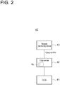
- FIG. 2 shows the configuration of a remote monitoring system 40 for remotely monitoring a control state of the wet flue gas desulfurization device 10 (see FIG. 1 ).
- the remote monitoring system 40 includes a distributed control system (DCS) 41 for the respective devices composing the combustion device 1 (see FIG. 1 ) and the wet flue gas desulfurization device (see FIG. 1 ), an edge server 42 electrically connected to the DCS 41 and equipped with the control device 15, and a remote monitoring device 43 such as a desktop personal computer or a tablet computer electrically connected to the edge server 42 via cloud or the virtual private network (VPN).
- DCS distributed control system
- VPN virtual private network
- the exhaust gas generated in the combustion device 1 flows through the pipe 2, flows into the absorption tower 11, and rises in the absorption tower 11.
- the absorption liquid flows through the circulation pipe 3, flows into the absorption tower 11, and flows down in the absorption tower 11.
- the absorption liquid flowing down in the absorption tower 11 is stored in the absorption tower 11, flows out of the absorption tower 11 by the circulation pumps 12a to 12c, and flows through the circulation pipe 3.
- the absorption liquid thus circulates in the absorption tower 11.
- the rising exhaust gas and the flow-down absorption liquid are brought into gas-liquid contact with each other.
- SO 2 contained in the exhaust gas reacts with CaCO 3 in the absorption liquid, precipitating gypsum (CaSO 4 ⁇ 2H20) in the absorption liquid, as indicated by the following reaction formula: SO 2 +CaCO 3 +2H 2 O+1/2O 2 ⁇ CaSO 4 ⁇ 2H 2 O+CO 2
- the SO 2 concentration in the effluent gas flowing out of the absorption tower 11 via the outflow pipe 16 is lower than the SO 2 concentration in the exhaust gas flowing into the absorption tower 11 via the pipe 2.
- the effluent gas flowing out of the absorption tower 11 flows through the outflow pipe 16 and is released to the atmosphere, in the middle of which the gas analyzer 17 measures the SO 2 concentration, and the measurement result is transmitted to the operation data reception unit 30 of the control device 15.
- the SO 2 concentration in the effluent gas tends to decrease as the circulation flow rate of the absorption liquid circulating in the absorption tower 11 increases, unless a CaCO 3 concentration in the absorption liquid fluctuates greatly.
- Controlling the circulation flow rate by controlling the number of circulation pumps 12a to 12c in operation by the control device 15 with a control method to be described later, it is possible to control the SO 2 concentration in the effluent gas, for example, it is possible to control the SO 2 concentration in the effluent gas to be not more than a preset set value.
- the gypsum precipitated in the absorption liquid in the absorption tower 11 is extracted from the absorption tower 11 by the gypsum slurry extraction pump 27 as the gypsum slurry.
- the gypsum slurry flows through the gypsum slurry extraction pipe 26 and flows into the gypsum separator 25.
- the gypsum and water are separated from each other in the gypsum separator 25.
- the gypsum is recovered, and the water is sent to a drainage facility (not shown).
- the control device 15 controls the opening degree of the absorbent slurry supply amount control valve 23, and supplies the absorbent slurry produced in the absorbent slurry production equipment 21 into the absorption tower 11 via the absorbent slurry supply pipe 22.
- the CaCO 3 concentration in the absorption liquid falls within a preset setting range, suppressing a large fluctuation in CaCO 3 concentration during desulfurization of the exhaust gas.
- FIG. 3 shows the outline of the method for controlling the wet flue gas desulfurization device 10 by the control device 15.
- the various kinds of operation data of the combustion device 1 and the wet flue gas desulfurization device 10 are collected in step S1.
- a first learning model is constructed by machine learning of the relationship between the various kinds of operation data and a future SO 2 concentration in the effluent gas flowing out of the absorption tower 11.
- a first relationship table to be described later is created by using the constructed first learning model.
- a circulation flow rate of the absorption liquid, at which the SO 2 concentration in the effluent gas is not more than the preset set value is decided based on the first relationship table.
- operation conditions of the circulation pumps 12a to 12c are adjusted based on the decided circulation flow rate.
- the SO 2 concentration in the effluent gas is controlled to be not more than the preset set value.
- step S12 a second learning model is constructed by machine learning of the relationship between the various kinds of operation data and a future CaCO 3 concentration in absorption liquid.
- step S13 a second relationship table to be described later is created by using the constructed second learning model.
- step S14 an absorbent slurry supply amount, in which the CaCO 3 concentration falls within a preset setting range, is decided based on the second relationship table.
- step S15 controlling the absorbent slurry supply part 13, that is, controlling the opening degree of the absorbent slurry supply amount control valve 23, the absorbent slurry is supplied into the absorption tower 11 by the decided supply amount.
- the CaCO 3 concentration in the absorption liquid falls within the preset setting range, suppressing a large fluctuation in CaCO 3 concentration during desulfurization of the exhaust gas.
- step S1 the operation data acquisition unit 20 acquires the various kinds of operation data of the combustion device 1 and the wet flue gas desulfurization device 10, and then the acquired various kinds of operation data are transmitted to the control device 15 to be received by the operation data reception unit 30, allowing the control device 15 to collect the various kinds of operation data.
- the various kinds of operation data include the SO 2 concentration in the effluent gas.
- step S2 the first learning model construction unit 38 constructs the first model by machine learning of the relationship between the various kinds of operations collected by the control device 15 and the future SO 2 concentration in the effluent gas.
- step S3 using the constructed first learning model, the first relationship table creation unit 31 creates the first relationship table indicating correlation between a circulation flow rate of the absorption liquid at first time and a predictive value of the SO 2 concentration in the effluent gas at second time which is time in the future relative to the first time. Since the first relationship table is created by using the first learning model constructed by machine learning, it is possible to rapidly create the first relationship table.
- the predictive value of the SO 2 concentration in the effluent gas is, for example, a predictive value of the SO 2 concentration a few minutes later from now.
- the various kinds of operation data at least include the SO 2 concentration in the effluent gas at any time and the circulation flow rate of the absorption liquid at time in the past relative to the any time by a time interval obtained by subtracting the first time from the second time.
- the future SO 2 concentration is predicted directly from the actual operation data including the SO 2 concentration in the effluent gas at the any time and the circulation flow rate of the absorption liquid at time in the past relative to the any time by the time interval obtained by subtracting the first time from the second time, making it possible to improve predictive performance of the future SO 2 concentration.
- the predictive performance of the future SO 2 concentration improves, as the interval between the first time and the second time is short.
- the interval between the first time and the second time is preferably the sum of a time taken until the SO 2 concentration in the effluent gas changes due to a change in circulation flow rate of the absorption liquid and a time required for the gas analyzer 17 to measure the SO 2 concentration.
- FIG. 4 shows a transition of the predictive value of the SO 2 concentration (top graph), a transition of the measurement value of the SO 2 concentration by the gas analyzer 17 (middle graph), and a transition of the true value of the SO 2 concentration (bottom graph), in the case in which the interval between the first time and the second time is the sum of the time taken until the SO 2 concentration in the effluent gas changes due to the change in circulation flow rate of the absorption liquid and the time required for the gas analyzer 17 to measure the SO 2 concentration.
- a value is older toward the right side, and the latest value is given at the leftmost side.
- the latest value of the measurement value of the SO 2 concentration by the gas analyzer 17 is a value at the first time
- the latest value of the predictive value of the SO 2 concentration is a value at the second time.
- An interval (i) between the latest value of the measurement value of the SO 2 concentration by the gas analyzer 17 and the latest value of the true value of the SO 2 concentration corresponds to the time required for the gas analyzer 17 to measure the SO 2 concentration, that is, a measurement delay.
- An interval (ii) between the latest value of the true value of the SO 2 concentration and the latest value of the predictive value of the SO 2 concentration corresponds to the time taken until the SO 2 concentration in the effluent gas changes due to the change in circulation flow rate of the absorption liquid.
- FIG. 5 shows an example of the first relationship table.
- the first relationship table is represented as a graph having the predictive value of the SO 2 concentration in the effluent gas on the abscissa and the circulation flow rate of the absorption liquid on the ordinate.
- the first relationship table need not necessarily be in such a form, but may be in a form of a matrix, a mathematical expression, or the like.
- the circulation flow rate decision unit 32 decides, based on the first relationship table, a circulation flow rate Q of the absorption liquid at which the future SO 2 concentration in the effluent gas reaches a preset set value SV.
- the circulation pump adjustment unit 33 decides the number of circulation pumps 12a to 12c in operation to be not less than the decided circulation flow rate Q, and causes the decided number of circulation pumps to operate. For example, in a case in which supply amounts when the three circulation pumps 12a to 12c operate, respectively, are the same, the circulation flow rate can be adjusted at three steps. It is possible to adjust the circulation flow rate more finely, as the number of circulation pumps increases. In addition, for example, in a case in which the supply amounts when the three circulation pumps 12a to 12c operate, respectively, are different from each other, the circulation flow rate can be adjusted at up to six steps by the combination of the circulation pumps to be operated. Furthermore, for example, if each of the three circulation pumps 12a to 12c can adjust the supply amount, the circulation flow rate can be adjusted more finely.
- adjustment of the circulation flow rate is not limited to be performed by controlling the number of circulation pumps.
- the supply amount of the circulation pump may be adjusted to obtain the circulation flow rate decided by the circulation flow rate decision unit 32, by using one circulation pump capable of adjusting the supply amount.
- the second learning model construction unit 39 constructs the second learning model by machine learning of the relationship between the various kinds of operation data collected by the control device 15 and the future CaCO 3 concentration in the absorption liquid in the absorption tower 11.
- the second relationship table creation unit 35 uses the constructed second learning model to create the second relationship table indicating correlation between a supply amount of the absorbent slurry to the absorption tower 11 at third time and a predictive value of the CaCO 3 concentration at fourth time which is time in the future relative to the third time. Since the second relationship table is created by using the second learning model constructed by machine learning, it is possible to rapidly create the second relationship table.
- the predictive value of the CaCO 3 concentration is, for example, a predictive value of the CaCO 3 concentration a few minutes later from now.
- the various kinds of operation data at least include the CaCO 3 concentration at any time and the supply amount of the absorbent slurry at time in the past relative to the any time by a time interval obtained by subtracting the third time from the fourth time.
- the future CaCO 3 concentration is predicted directly from the actual operation data including the CaCO 3 concentration at the any time and the supply amount of the absorbent slurry at the time in the past relative to the any time by the time interval obtained by subtracting the third time from the fourth time, making it possible to improve predictive performance of the future CaCO 3 concentration.
- the CaCO 3 concentration at the any time uses a value calculated with a simulation model by mass balance calculation.
- a sensor for detecting the CaCO 3 concentration is generally expensive. Thus, providing such a sensor increases the cost of the wet flue gas desulfurization device 10. However, if the CaCO 3 concentration is calculated with the simulation model by mass balance calculation, the expensive sensor is no longer needed, making it possible to suppress the increase in cost of the wet flue gas desulfurization device 10.
- the interval between the third time and the fourth time is preferably a time taken until the CaCO 3 concentration changes due to a change in supply amount of the absorbent slurry.
- a transition of the predictive value of the supply amount of the absorbent slurry and the transition of the true value are in the same relationship as the transition of the predictive value of the SO 2 concentration (top graph) and the transition of the true value (bottom graph) in FIG. 4 , respectively.
- the CaCO 3 concentration is calculated with the simulation model by mass balance calculation.
- the transition of the predictive value of the supply amount of the absorbent slurry, the transition of the measurement value by the sensor, and the transition of the true value are in the same relationship as the various transitions (respective graphs) of the SO 2 concentration in FIG. 4 , respectively.
- the number of steps required for the SO 2 concentration in the effluent gas flowing out of the absorption tower 11 to change is larger than the number of steps required for the CaCO 3 concentration to change.
- a delay in control of the SO 2 concentration is long, as compared with control of the CaCO 3 concentration.
- making the time from the third time to the fourth time shorter than the time from the first time to the second time it is possible to appropriately consider an influence of the control delay. Accordingly, it is possible to further improve predictive performance of the future CaCO 3 concentration.
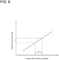
- FIG. 6 shows an example of the second relationship table.
- the second relationship table is represented as a graph having the predictive value of the CaCO 3 concentration on the abscissa and the supply amount of the absorbent slurry on the ordinate.
- the second relationship table need not necessarily be in such a form, but may be in a form of a matrix, a mathematical expression, or the like.
- the absorbent slurry supply amount decision unit 36 decides, based on the second relationship table, a supply amount F of the absorbent slurry in which the future CaCO 3 concentration falls within the preset setting range R.
- step S15 the absorbent slurry supply control unit 37 controls the opening degree of the absorbent slurry supply amount control valve 23 such that the supply amount of the absorbent slurry supplied into the absorption tower 11 via the absorbent slurry supply pipe 22 is close to the decided supply amount F of the absorbent slurry.
- the absorbent slurry supply control unit 37 controls the opening degree of the absorbent slurry supply amount control valve 23 such that the supply amount of the absorbent slurry supplied into the absorption tower 11 via the absorbent slurry supply pipe 22 is close to the decided supply amount F of the absorbent slurry.
- the future SO 2 concentration is predicted directly from the actual operation data, by creating the first relationship table between the circulation flow rate of the absorption liquid at the first time and the SO 2 concentration in the effluent gas flowing out of the absorption tower 11 at the second time which is the time in the future relative to the first time, from the operation data of the combustion device 1 and the operation data of the wet flue gas desulfurization device 10 including the circulation flow rate of the absorption liquid.
- the first relationship table improved in predictive performance of the future SO 2 concentration.
- the circulation flow rate of the absorption liquid at the first time at which the SO 2 concentration in the effluent gas at the second time is not more than the preset set value is decided, and at the first time, the operation conditions of the circulation pumps 12a to 12c are adjusted based on the decided circulation flow rate.
- the operation conditions of the circulation pumps 12a to 12c are adjusted based on the decided circulation flow rate.
- the CaCO 3 concentration in the absorption liquid is set within the preset setting range by steps S12 to S15.
- the control device 15 may not include the second learning model construction unit 39, the second relationship table creation unit 35, the absorbent slurry supply amount decision unit 36, and the absorbent slurry supply control unit 37.
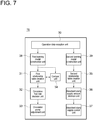
- the control device 15 includes a comparison unit 34 electrically connected to the operation data reception unit 30 and the first relationship table creation unit 31.
- the comparison unit 34 may reconstruct the first learning model by machine learning of the various operation data and the future SO 2 concentration in the effluent gas, if a difference between an analysis result by the gas analyzer 17 acquired at the second time and the predictive value of the SO 2 concentration in the effluent gas at the second time reaches, for example, not less than a preset threshold after the first relationship table is created, and may recreate the first relationship table by using the reconstructed first learning model.
- some sort of abnormality may be occurring in a process, if the difference between the analysis result by the gas analyzer 17 acquired at the second time and the predictive value of the SO 2 concentration in the effluent gas at the second time reaches not less than the preset threshold after the first relationship table is created.
- it is possible to early detect the abnormality in the process by displaying a warning or the like informing the possibility of the abnormality on, for example, the remote monitoring device 43 (see FIG. 2 ).
- CaCO 3 is used as the SO 2 absorbent.
- the SO 2 absorbent is not limited to CaCO 3 .
- the SO 2 absorbent for example, magnesium hydroxide (Mg(OH)2) or the like can also be used.
Landscapes
- Engineering & Computer Science (AREA)
- Chemical & Material Sciences (AREA)
- Analytical Chemistry (AREA)
- Chemical Kinetics & Catalysis (AREA)
- General Chemical & Material Sciences (AREA)
- Oil, Petroleum & Natural Gas (AREA)
- Environmental & Geological Engineering (AREA)
- Health & Medical Sciences (AREA)
- Software Systems (AREA)
- Biomedical Technology (AREA)
- General Engineering & Computer Science (AREA)
- Theoretical Computer Science (AREA)
- Computer Vision & Pattern Recognition (AREA)
- Evolutionary Computation (AREA)
- Artificial Intelligence (AREA)
- General Physics & Mathematics (AREA)
- Physics & Mathematics (AREA)
- Medical Informatics (AREA)
- Mechanical Engineering (AREA)
- Mathematical Physics (AREA)
- Computing Systems (AREA)
- Data Mining & Analysis (AREA)
- Automation & Control Theory (AREA)
- Treating Waste Gases (AREA)
- Chimneys And Flues (AREA)
- Gas Separation By Absorption (AREA)
- Feedback Control In General (AREA)
Abstract
Description
- The present disclosure relates to a method for controlling a wet flue gas desulfurization device, a device for controlling the wet flue gas desulfurization device, and a remote monitoring system comprising the device for controlling the wet flue gas desulfurization device.
- In a wet flue gas desulfurization device, an exhaust gas generated in a combustion device such as a boiler is introduced into an absorption tower of a desulfurization device and is brought into gas-liquid contact with an absorption liquid circulating through the absorption tower. In the course of the gas-liquid contact, sulfur dioxide (SO2) in the exhaust gas is absorbed into the absorption liquid by reaction between SO2 in the exhaust gas and an absorbent (for example, calcium carbonate) in the absorption liquid, removing SO2 from the exhaust gas (desulfurizing the exhaust gas). On the other hand, the absorption liquid having absorbed SO2 falls and is stored in a storage tank below the absorption tower. The absorbent is supplied to the storage tank. The absorption liquid whose absorption performance is recovered by the supplied absorbent is supplied to the upper part of the absorption tower by a circulation pump, and is brought into gas-liquid contact with the exhaust gas (absorption of SO2). The circulation pump for circulating the absorption liquid consumes a lot of power. Thus, conventionally, in order to suppress power consumption, a required circulation flow rate of the absorption liquid is calculated based on, for example, the flow rate of the exhaust gas flowing into the absorption tower and the SO2 concentration in the exhaust gas to control the number of circulation pumps in operation.
- A wet flue gas desulfurization device of
Patent Document 1 identifies the current desulfurization performance of a desulfurization device based on an operation model of the desulfurization device, obtains, from operation data of a combustion device and the desulfurization device and a load request signal of the combustion device, future operation data and a predictive value of a future SO2 concentration in an exhaust gas flowing out of an absorption tower, and controls the circulation flow rate of an absorption liquid based on the predictive value of the future SO2 concentration. - Patent Document 1:
JP2984933B - However, in the wet flue gas desulfurization device of
Patent Document 1, since the future operation data is predicted by linear regression from the load request signal of the combustion device, and the future SO2 concentration is predicted from the future operation data, the problem arises in that prediction performance is low. - In view of the above, an object of at least one embodiment of the present disclosure is to provide a method for controlling a wet flue gas desulfurization device capable of appropriately adjusting an operation condition of a circulation pump for circulating an absorption liquid in an absorption tower of the wet flue gas desulfurization device, a device for controlling the wet flue gas desulfurization device, and a remote monitoring system comprising the device for controlling the wet flue gas desulfurization device.
-
- (1) A method for controlling a wet flue gas desulfurization device according to at least one embodiment of the present invention is a method for controlling a wet flue gas desulfurization device including an absorption tower, and at least one circulation pump for circulating an absorption liquid in the absorption tower, and performing desulfurization by bringing the absorption liquid into gas-liquid contact with an exhaust gas generated in a combustion device, in the absorption tower, the method including a step of constructing a first learning model by machine learning of a relationship between a future sulfur dioxide concentration at an outlet of the absorption tower, and operation data of the combustion device and operation data of the wet flue gas desulfurization device including a circulation flow rate of the absorption liquid, a step of creating, by using the first learning model, a first relationship table between a circulation flow rate of the absorption liquid at first time and a sulfur dioxide concentration in an effluent gas flowing out of the absorption tower at second time which is time in the future relative to the first time, a step of deciding, based on the first relationship table, the circulation flow rate of the absorption liquid at the first time, at which the sulfur dioxide concentration in the effluent gas at the second time is not more than a preset set value, and a step of adjusting an operation condition of the at least one circulation pump based on the decided circulation flow rate, at the first time.
With the above method (1), the future sulfur dioxide concentration is predicted directly from the actual operation data, by creating the first relationship table between the circulation flow rate of the absorption liquid at the first time and the sulfur dioxide concentration in the effluent gas flowing out of the absorption tower at the second time which is the time in the future relative to the first time, from the operation data of the combustion device and the operation data of the wet flue gas desulfurization device including the circulation flow rate of the absorption liquid. Thus, it is possible to obtain the first relationship table improved in predictive performance of the future sulfur dioxide concentration. Based on the obtained first relationship table, the circulation flow rate of the absorption liquid at the first time at which the sulfur dioxide concentration in the effluent gas at the second time is not more than the preset set value is decided, and at the first time, the operation condition of the at least one circulation pump is adjusted based on the decided circulation flow rate. Thus, it is possible to appropriately adjust the operation condition of the circulation pump.
Moreover, with the above method (1), since the first relationship table is created by using the first learning model constructed by machine learning of the relationship between the future sulfur dioxide concentration at the outlet of the absorption tower, and the operation data of the combustion device and the operation data of the wet flue gas desulfurization device including the circulation flow rate of the absorption liquid, it is possible to rapidly create the first relationship table. - (2) In some embodiments, in the above method (1), the operation data of the wet flue gas desulfurization device including the circulation flow rate of the absorption liquid includes a sulfur dioxide concentration in the effluent gas at any time, and a circulation flow rate of the absorption liquid at time in the past relative to the any time by a time interval obtained by subtracting the first time from the second time.
With the above method (2), since the future sulfur dioxide concentration is predicted directly from the actual operation data including the sulfur dioxide concentration in the effluent gas at the any time and the circulation flow rate of the absorption liquid at the time in the past relative to the any time by the time interval obtained by subtracting the first time from the second time, it is possible to improve predictive performance of the future sulfur dioxide concentration. - (3) In some embodiments, in the above method (1) or (2), the wet flue gas desulfurization device further includes a gas analyzer for measuring the sulfur dioxide concentration in the effluent gas, and the method further includes a step of comparing an analysis result by the gas analyzer acquired at the second time with a predictive value of the sulfur dioxide concentration in the effluent gas at the second time.
With the above method (3), some sort of abnormality may be occurring in a process, if the analysis result by the gas analyzer significantly deviates from the predictive value of the sulfur dioxide concentration. Thus, it is possible to early detect the abnormality in the process. - (4) In some embodiments, in the above method (3), the method for controlling the wet flue gas desulfurization device further includes, after creating the first relationship table, a step of reconstructing, based on a difference between the analysis result and the predictive value of the sulfur dioxide concentration in the effluent gas, the first learning model by machine learning of the relationship between the future sulfur dioxide concentration at the outlet of the absorption tower, and the operation data of the combustion device and the operation data of the wet flue gas desulfurization device including the circulation flow rate of the absorption liquid, and creating the first relationship table by using the reconstructed first learning model.
With the above method (4), if the difference between the analysis result by the gas analyzer and the predictive value of the sulfur dioxide concentration in the effluent gas is large, the first learning model is recreated by machine learning from the operation data of the combustion device and the operation data of the wet flue gas desulfurization device including the circulation flow rate of the absorption liquid, and the first relationship table is recreated by using the reconstructed first learning model, thereby it is possible to obtain the first relationship table further improved in predictive performance of the future sulfur dioxide concentration. - (5) In some embodiments, in any one of the above methods (1) to (4), the wet flue gas desulfurization device further includes an absorbent slurry supply part for supplying, to the absorption tower, an absorbent slurry which is a slurry of an absorbent included in the absorption liquid, and the method further includes a step of constructing a second learning model by machine learning of a relationship between a future absorbent concentration, and the operation data of the combustion device and the operation data of the wet flue gas desulfurization device including the circulation flow rate of the absorption liquid, a step of creating, by using the second learning model, a second relationship table between a supply amount of the absorbent slurry to the absorption tower at third time and a concentration of the absorbent in the absorption liquid at fourth time which is time in future relative to the third time, a step of deciding, based on the second relationship table, the supply amount of the absorbent slurry at the third time, in which the concentration of the absorbent at the fourth time falls within a preset setting range, and a step of controlling the absorbent slurry supply part based on the decided supply amount of the absorbent slurry, at the third time.
With the above method (5), the future absorbent concentration is predicted directly from the actual operation data, by creating the second relationship table between the supply amount of the absorbent slurry to the absorption tower at the third time and the concentration of the absorbent in the absorption liquid at the fourth time which is the time in the future relative to the third time, from the operation data of the combustion device and the operation data of the wet flue gas desulfurization device including the circulation flow rate of the absorption liquid. Thus, it is possible to obtain the second relationship table improved in predictive performance of the future absorbent concentration. Based on the obtained second relationship table, the supply amount of the absorbent slurry at the third time in which the absorbent concentration at the fourth time falls within the preset setting range is decided, and at the third time, the absorbent slurry supply part is controlled based on the decided supply amount of the absorbent slurry, thereby it is possible to suppress a fluctuation in absorbent concentration. Thus, it is possible to suppress excessive consumption of the absorbent, and to circulate the absorption liquid at an appropriate circulation flow rate.
Moreover, with the above method (5), since the second relationship table is created by using the second learning model constructed by machine learning of the relationship between the future absorbent concentration, and the operation data of the combustion device and the operation data of the wet flue gas desulfurization device including the circulation flow rate of the absorption liquid, it is possible to rapidly create the second relationship table. - (6) In some embodiments, in the above method (5), the operation data of the wet flue gas desulfurization device including the circulation flow rate of the absorption liquid includes a concentration of the absorbent at any time, and a supply amount of the absorbent slurry at time in the past relative to the any time by a time interval obtained by subtracting the third time from the fourth time.
With the above method (6), since the future absorbent concentration is predicted directly from the actual operation data including the absorbent concentration at the any time and the supply amount of the absorbent slurry at the time in the past relative to the any time by the time interval obtained by subtracting the third time from the fourth time, it is possible to improve predictive performance of the future absorbent concentration. - (7) In some embodiments, in the above method (6), the concentration of the absorbent is calculated with a simulation model by mass balance calculation.
A sensor for detecting the absorbent concentration is generally expensive. Thus, providing such a sensor increases the cost of the wet flue gas desulfurization device. However, with the above method (7), since the absorbent concentration can be calculated with the simulation model by mass balance calculation, the expensive sensor is no longer needed, making it possible to suppress the increase in cost of the wet flue gas desulfurization device. - (8) In some embodiments, in any one of the above methods (5) to (7), an interval from the third time to the fourth time is shorter than an interval from the first time to the second time.
The change in sulfur dioxide concentration in the effluent gas undergoes a plurality of steps in order of an increase in circulation flow rate of the absorption liquid, gas-liquid contact with the exhaust gas, and a decrease in sulfur dioxide concentration. On the other hand, the change in absorbent concentration has the small number of required steps in order of supply of the absorbent slurry and an increase in absorbent concentration. Accordingly, a delay in control of the sulfur dioxide concentration is large, as compared with control of the absorbent concentration. However, with the above method (8), since the time from the third time to the fourth time is shorter than the time from the first time to the second time, it is possible to appropriately consider an influence of the control delay. Thus, it is possible to further improve predictive performance of the future absorbent concentration. - (9) A device for controlling a wet flue gas desulfurization device according to at least one embodiment of the present invention is a device for controlling a wet flue gas desulfurization device including an absorption tower, and at least one circulation pump for circulating an absorption liquid in the absorption tower, and performing desulfurization by bringing the absorption liquid into gas-liquid contact with an exhaust gas generated in a combustion device, in the absorption tower, the device including a first learning model construction unit for constructing a learning model by machine learning of a relationship between a future sulfur dioxide concentration at an outlet of the absorption tower, and operation data of the combustion device and operation data of the wet flue gas desulfurization device including a circulation flow rate of the absorption liquid, a first relationship table creation unit for creating, by using the learning model, a first relationship table between a circulation flow rate of the absorption liquid at first time and a sulfur dioxide concentration in an effluent gas flowing out of the absorption tower at second time which is time in the future relative to the first time, a circulation flow rate decision unit for deciding, based on the first relationship table, the circulation flow rate of the absorption liquid at the first time, at which the sulfur dioxide concentration in the effluent gas at the second time is not more than a preset set value, and a circulation pump adjustment unit for adjusting an operation condition of the at least one circulation pump based on the decided circulation flow rate, at the first time.
With the above configuration (9), the future sulfur dioxide concentration is predicted directly from the actual operation data, by creating the first relationship table between the circulation flow rate of the absorption liquid at the first time and the sulfur dioxide concentration in the effluent gas flowing out of the absorption tower at the second time which is the time in the future relative to the first time, from the operation data of the combustion device and the operation data of the wet flue gas desulfurization device including the circulation flow rate of the absorption liquid. Thus, it is possible to obtain the first relationship table improved in predictive performance of the future sulfur dioxide concentration. Based on the obtained first relationship table, the circulation flow rate of the absorption liquid at the first time at which the sulfur dioxide concentration in the effluent gas at the second time is not more than the preset set value is decided, and at the first time, the operation condition of the at least one circulation pump is adjusted based on the decided circulation flow rate. Thus, it is possible to appropriately adjust the operation condition of the circulation pump. - (10) In some embodiments, in the above configuration (9), the wet flue gas desulfurization device further includes an absorbent slurry supply part for supplying, to the absorption tower, an absorbent slurry which is a slurry of an absorbent included in the absorption liquid, and the device further includes: a second learning model construction unit for constructing a second learning model by machine learning of a relationship between a future absorbent concentration, and the operation data of the combustion device and the operation data of the wet flue gas desulfurization device including the circulation flow rate of the absorption liquid, a second relationship table creation unit for creating, by using the second learning model, a second relationship table between a supply amount of the absorbent slurry to the absorption tower at third time and a concentration of the absorbent in the absorption liquid at fourth time which is time in future relative to the third time, an absorbent slurry supply amount decision unit for deciding, based on the second relationship table, the supply amount of the absorbent slurry at the third time, in which the concentration of the absorbent at the fourth time falls within a preset setting range, and an absorbent slurry supply control unit for controlling the absorbent slurry supply part based on the decided supply amount of the absorbent slurry, at the third time.
With the above configuration (10), the future absorbent concentration is predicted directly from the actual operation data, by creating the second relationship table between the supply amount of the absorbent slurry to the absorption tower at the third time and the concentration of the absorbent in the absorption liquid at the fourth time which is the time in the future relative to the third time, from the operation data of the combustion device and the operation data of the wet flue gas desulfurization device including the circulation flow rate of the absorption liquid. Thus, it is possible to obtain the second relationship table improved in predictive performance of the future absorbent concentration. Based on the obtained second relationship table, the supply amount of the absorbent slurry at the third time in which the absorbent concentration at the fourth time falls within the preset setting range is decided, and at the third time, the absorbent slurry supply part is controlled based on the decided supply amount of the absorbent slurry, thereby it is possible to suppress a fluctuation in absorbent concentration. Thus, it is possible to suppress excessive consumption of the absorbent, and to circulate the absorption liquid at an appropriate circulation flow rate. - (11) A remote monitoring system according to at least one embodiment of the present invention includes the device for controlling the wet flue gas desulfurization device according to any one of the above configuration (9) or (10), and a remote monitoring device electrically connected to the device for controlling the wet flue gas desulfurization device.
- With the above configuration (11), it is possible to monitor a control state of the wet flue gas desulfurization device.
- According to at least one embodiment of the present disclosure, a future sulfur dioxide concentration is predicted directly from actual operation data, by creating a first relationship table between a circulation flow rate of an absorption liquid at first time and a sulfur dioxide concentration in an effluent gas flowing out of an absorption tower at second time which is time in the future relative to the first time, from operation data of a combustion device and operation data of a wet flue gas desulfurization device including a circulation flow rate of the absorption liquid. Thus, it is possible to obtain a first relationship table improved in predictive performance of the future sulfur dioxide concentration. Based on the obtained first relationship table, the circulation flow rate of the absorption liquid at the first time at which the sulfur dioxide concentration in the effluent gas at the second time is not more than a preset set value is decided, and at the first time, an operation condition of at least one circulation pump is adjusted based on the decided circulation flow rate. Thus, it is possible to appropriately adjust the operation condition of the circulation pump.
-
-
FIG. 1 is a schematic diagram showing the configuration of a wet flue gas desulfurization device including a device for controlling the wet flue gas desulfurization device according to an embodiment of the present disclosure. -
FIG. 2 is a schematic diagram showing the configuration of a remote monitoring system according to an embodiment of the present disclosure. -
FIG. 3 is a flowchart of a method for controlling the wet flue gas desulfurization device according to an embodiment of the present disclosure. -
FIG. 4 is a graph showing respective transitions of a predictive value of an SO2 concentration in an effluent gas, a measurement value of the SO2 concentration by a gas analyzer, and a true value of a predictive value of the SO2 concentration. -
FIG. 5 is a graph schematically showing an example of a first relationship table created in the method for controlling the wet flue gas desulfurization device according to an embodiment of the present disclosure. -
FIG. 6 is a graph schematically showing an example of a second relationship table created in the method for controlling the wet flue gas desulfurization device according to an embodiment of the present disclosure. -
FIG. 7 is a schematic diagram showing the configuration of a modified example of the device for controlling the wet flue gas desulfurization device according to an embodiment of the present disclosure. - Embodiments of the present invention will now be described in detail with reference to the accompanying drawings. However, the scope of the present invention is not limited to the following embodiments. It is intended that dimensions, materials, shapes, relative positions and the like of components described in the embodiments shall be interpreted as illustrative only and not intended to limit the scope of the present invention.
- As shown in
FIG. 1 , a wet fluegas desulfurization device 10 is provided to desulfurize an exhaust gas generated in acombustion device 1 such as a boiler. The wet fluegas desulfurization device 10 includes anabsorption tower 11 communicating with thecombustion device 1 via apipe 2, a plurality of (for example, three)circulation pumps circulation pipe 3 for an absorption liquid circulating in theabsorption tower 11, an absorbentslurry supply part 13 for supplying, to theabsorption tower 11, a slurry (absorbent slurry) of calcium carbonate (CaCO3) serving as an absorbent included in the absorption liquid, and agypsum recovery part 14 for recovering gypsum in the absorption liquid. Theabsorption tower 11 is provided with anoutflow pipe 16 for the exhaust gas desulfurized by an operation to be described later to flow out of theabsorption tower 11 as the effluent gas. Theoutflow pipe 16 is provided with agas analyzer 17 for measuring the SO2 concentration in the effluent gas. - The absorbent
slurry supply part 13 includes an absorbentslurry production equipment 21 for producing the absorbent slurry, an absorbentslurry supply pipe 22 for causing the absorbentslurry production equipment 21 and theabsorption tower 11 to communicate with each other, and an absorbent slurry supplyamount control valve 23 for controlling the flow rate of the absorbent slurry flowing through the absorbentslurry supply pipe 22. Thegypsum recovery part 14 includes agypsum separator 25, a gypsumslurry extraction pipe 26 for causing thegypsum separator 25 and theabsorption tower 11 to communicate with each other, and a gypsumslurry extraction pump 27 disposed on the gypsumslurry extraction pipe 26. - The wet flue
gas desulfurization device 10 is provided with acontrol device 15 of the wet fluegas desulfurization device 10. Thecontrol device 15 includes an operationdata reception unit 30 electrically connected to an operationdata acquisition unit 20, which includes various detectors for acquiring various kinds of operation data (for example, temperatures and pressures in various sections, flow rates of various fluids, and the like) of thecombustion device 1 and the wet fluegas desulfurization device 10. The operationdata acquisition unit 20 includes thegas analyzer 17. - The
control device 15 includes a first learningmodel construction unit 38 electrically connected to the operationdata reception unit 30, a first relationshiptable creation unit 31 electrically connected to the first learningmodel construction unit 38, a circulation flowrate decision unit 32 electrically connected to the first relationshiptable creation unit 31, and a circulationpump adjustment unit 33 electrically connected to the circulation flowrate decision unit 32. The circulationpump adjustment unit 33 is electrically connected to the circulation pumps 12a, 12b, 12c. - The
control device 15 further includes a second learningmodel construction unit 39 electrically connected to the operationdata reception unit 30, a second relationshiptable creation unit 35 electrically connected to the second learningmodel construction unit 39, an absorbent slurry supplyamount decision unit 36 electrically connected to the second relationshiptable creation unit 35, and an absorbent slurrysupply control unit 37 electrically connected to the absorbent slurry supplyamount decision unit 36. The absorbent slurrysupply control unit 37 is electrically connected to the absorbent slurry supplyamount control valve 23. -
FIG. 2 shows the configuration of aremote monitoring system 40 for remotely monitoring a control state of the wet flue gas desulfurization device 10 (seeFIG. 1 ). Theremote monitoring system 40 includes a distributed control system (DCS) 41 for the respective devices composing the combustion device 1 (seeFIG. 1 ) and the wet flue gas desulfurization device (seeFIG. 1 ), anedge server 42 electrically connected to theDCS 41 and equipped with thecontrol device 15, and aremote monitoring device 43 such as a desktop personal computer or a tablet computer electrically connected to theedge server 42 via cloud or the virtual private network (VPN). In general, it is possible to remotely monitor the control state of the wet fluegas desulfurization device 10 by theremote monitoring device 43 present in a location away from theedge server 42. - Next, an operation in which the wet flue
gas desulfurization device 10 desulfurizes the exhaust gas generated in thecombustion device 1 will be described. - As shown in
FIG. 1 , the exhaust gas generated in thecombustion device 1 flows through thepipe 2, flows into theabsorption tower 11, and rises in theabsorption tower 11. Operating at least one of the circulation pumps 12a to 12c, the absorption liquid flows through thecirculation pipe 3, flows into theabsorption tower 11, and flows down in theabsorption tower 11. The absorption liquid flowing down in theabsorption tower 11 is stored in theabsorption tower 11, flows out of theabsorption tower 11 by the circulation pumps 12a to 12c, and flows through thecirculation pipe 3. The absorption liquid thus circulates in theabsorption tower 11. - In the
absorption tower 11, the rising exhaust gas and the flow-down absorption liquid are brought into gas-liquid contact with each other. SO2 contained in the exhaust gas reacts with CaCO3 in the absorption liquid, precipitating gypsum (CaSO4·2H20) in the absorption liquid, as indicated by the following reaction formula:
SO2+CaCO3+2H2O+1/2O2→CaSO4·2H2O+CO2
- Since a part of SO2 in the exhaust gas is thus removed as gypsum into the absorption liquid, that is, the exhaust gas is desulfurized, the SO2 concentration in the effluent gas flowing out of the
absorption tower 11 via theoutflow pipe 16 is lower than the SO2 concentration in the exhaust gas flowing into theabsorption tower 11 via thepipe 2. The effluent gas flowing out of theabsorption tower 11 flows through theoutflow pipe 16 and is released to the atmosphere, in the middle of which thegas analyzer 17 measures the SO2 concentration, and the measurement result is transmitted to the operationdata reception unit 30 of thecontrol device 15. - The SO2 concentration in the effluent gas tends to decrease as the circulation flow rate of the absorption liquid circulating in the
absorption tower 11 increases, unless a CaCO3 concentration in the absorption liquid fluctuates greatly. Controlling the circulation flow rate by controlling the number ofcirculation pumps 12a to 12c in operation by thecontrol device 15 with a control method to be described later, it is possible to control the SO2 concentration in the effluent gas, for example, it is possible to control the SO2 concentration in the effluent gas to be not more than a preset set value. - The gypsum precipitated in the absorption liquid in the
absorption tower 11 is extracted from theabsorption tower 11 by the gypsumslurry extraction pump 27 as the gypsum slurry. The gypsum slurry flows through the gypsumslurry extraction pipe 26 and flows into thegypsum separator 25. The gypsum and water are separated from each other in thegypsum separator 25. The gypsum is recovered, and the water is sent to a drainage facility (not shown). - CaCO3 in the absorption liquid reacts with SO2 to be gypsum, decreasing the CaCO3 concentration in the absorption liquid as the exhaust gas is desulfurized. With the control method to be described later, the
control device 15 controls the opening degree of the absorbent slurry supplyamount control valve 23, and supplies the absorbent slurry produced in the absorbentslurry production equipment 21 into theabsorption tower 11 via the absorbentslurry supply pipe 22. Thus, the CaCO3 concentration in the absorption liquid falls within a preset setting range, suppressing a large fluctuation in CaCO3 concentration during desulfurization of the exhaust gas. - Next, the method for controlling the wet flue
gas desulfurization device 10 by thecontrol device 15 will be described. -
FIG. 3 shows the outline of the method for controlling the wet fluegas desulfurization device 10 by thecontrol device 15. The various kinds of operation data of thecombustion device 1 and the wet fluegas desulfurization device 10 are collected in step S1. Then, in step S2, a first learning model is constructed by machine learning of the relationship between the various kinds of operation data and a future SO2 concentration in the effluent gas flowing out of theabsorption tower 11. Next, in step S3, a first relationship table to be described later is created by using the constructed first learning model. In subsequent step S4, a circulation flow rate of the absorption liquid, at which the SO2 concentration in the effluent gas is not more than the preset set value, is decided based on the first relationship table. In step S5, operation conditions of the circulation pumps 12a to 12c are adjusted based on the decided circulation flow rate. Thus, the SO2 concentration in the effluent gas is controlled to be not more than the preset set value. - Moreover, after step S1, besides steps S2 to S5, in step S12, a second learning model is constructed by machine learning of the relationship between the various kinds of operation data and a future CaCO3 concentration in absorption liquid. Next, in step S13, a second relationship table to be described later is created by using the constructed second learning model. In subsequent step S14, an absorbent slurry supply amount, in which the CaCO3 concentration falls within a preset setting range, is decided based on the second relationship table. In step S15, controlling the absorbent
slurry supply part 13, that is, controlling the opening degree of the absorbent slurry supplyamount control valve 23, the absorbent slurry is supplied into theabsorption tower 11 by the decided supply amount. Thus, the CaCO3 concentration in the absorption liquid falls within the preset setting range, suppressing a large fluctuation in CaCO3 concentration during desulfurization of the exhaust gas. - Next, the respective steps of the method for controlling the wet flue
gas desulfurization device 10 by thecontrol device 15 will be described in detail. - In step S1, as shown in
FIG. 1 , the operationdata acquisition unit 20 acquires the various kinds of operation data of thecombustion device 1 and the wet fluegas desulfurization device 10, and then the acquired various kinds of operation data are transmitted to thecontrol device 15 to be received by the operationdata reception unit 30, allowing thecontrol device 15 to collect the various kinds of operation data. As described above, since the operationdata acquisition unit 20 includes thegas analyzer 17, the various kinds of operation data include the SO2 concentration in the effluent gas. - In step S2, the first learning
model construction unit 38 constructs the first model by machine learning of the relationship between the various kinds of operations collected by thecontrol device 15 and the future SO2 concentration in the effluent gas. In step S3, using the constructed first learning model, the first relationshiptable creation unit 31 creates the first relationship table indicating correlation between a circulation flow rate of the absorption liquid at first time and a predictive value of the SO2 concentration in the effluent gas at second time which is time in the future relative to the first time. Since the first relationship table is created by using the first learning model constructed by machine learning, it is possible to rapidly create the first relationship table. - In the first relationship table, provided that the circulation flow rate of the absorption liquid and the predictive value of the SO2 concentration in the effluent gas are different in time and the circulation flow rate of the absorption liquid is set to a current value, the predictive value of the SO2 concentration in the effluent gas is, for example, a predictive value of the SO2 concentration a few minutes later from now. Thus, the various kinds of operation data at least include the SO2 concentration in the effluent gas at any time and the circulation flow rate of the absorption liquid at time in the past relative to the any time by a time interval obtained by subtracting the first time from the second time. The future SO2 concentration is predicted directly from the actual operation data including the SO2 concentration in the effluent gas at the any time and the circulation flow rate of the absorption liquid at time in the past relative to the any time by the time interval obtained by subtracting the first time from the second time, making it possible to improve predictive performance of the future SO2 concentration. The predictive performance of the future SO2 concentration improves, as the interval between the first time and the second time is short. Thus, the interval between the first time and the second time is preferably the sum of a time taken until the SO2 concentration in the effluent gas changes due to a change in circulation flow rate of the absorption liquid and a time required for the
gas analyzer 17 to measure the SO2 concentration. -
FIG. 4 shows a transition of the predictive value of the SO2 concentration (top graph), a transition of the measurement value of the SO2 concentration by the gas analyzer 17 (middle graph), and a transition of the true value of the SO2 concentration (bottom graph), in the case in which the interval between the first time and the second time is the sum of the time taken until the SO2 concentration in the effluent gas changes due to the change in circulation flow rate of the absorption liquid and the time required for thegas analyzer 17 to measure the SO2 concentration. In each of the graphs, a value is older toward the right side, and the latest value is given at the leftmost side. The latest value of the measurement value of the SO2 concentration by thegas analyzer 17 is a value at the first time, and the latest value of the predictive value of the SO2 concentration is a value at the second time. An interval (i) between the latest value of the measurement value of the SO2 concentration by thegas analyzer 17 and the latest value of the true value of the SO2 concentration corresponds to the time required for thegas analyzer 17 to measure the SO2 concentration, that is, a measurement delay. An interval (ii) between the latest value of the true value of the SO2 concentration and the latest value of the predictive value of the SO2 concentration corresponds to the time taken until the SO2 concentration in the effluent gas changes due to the change in circulation flow rate of the absorption liquid. -
FIG. 5 shows an example of the first relationship table. In the present embodiment, the first relationship table is represented as a graph having the predictive value of the SO2 concentration in the effluent gas on the abscissa and the circulation flow rate of the absorption liquid on the ordinate. However, the first relationship table need not necessarily be in such a form, but may be in a form of a matrix, a mathematical expression, or the like. In step S4, the circulation flowrate decision unit 32 decides, based on the first relationship table, a circulation flow rate Q of the absorption liquid at which the future SO2 concentration in the effluent gas reaches a preset set value SV. - In step S5, as shown in
FIG. 1 , the circulationpump adjustment unit 33 decides the number ofcirculation pumps 12a to 12c in operation to be not less than the decided circulation flow rate Q, and causes the decided number of circulation pumps to operate. For example, in a case in which supply amounts when the threecirculation pumps 12a to 12c operate, respectively, are the same, the circulation flow rate can be adjusted at three steps. It is possible to adjust the circulation flow rate more finely, as the number of circulation pumps increases. In addition, for example, in a case in which the supply amounts when the threecirculation pumps 12a to 12c operate, respectively, are different from each other, the circulation flow rate can be adjusted at up to six steps by the combination of the circulation pumps to be operated. Furthermore, for example, if each of the threecirculation pumps 12a to 12c can adjust the supply amount, the circulation flow rate can be adjusted more finely. - Note that adjustment of the circulation flow rate is not limited to be performed by controlling the number of circulation pumps. The supply amount of the circulation pump may be adjusted to obtain the circulation flow rate decided by the circulation flow
rate decision unit 32, by using one circulation pump capable of adjusting the supply amount. - Thus adjusting the circulation flow rate of the absorption liquid circulating in the
absorption tower 11, it is possible to control the future SO2 concentration in the effluent gas to be not more than the preset set value. However, this requires that there is no large fluctuation in CaCO3 concentration in the absorption liquid. Accordingly, in the present embodiment, as described above, besides steps S2 to S5, in steps S12 to S15, the CaCO3 concentration in the absorption liquid is controlled to fall within the preset setting range. Next, each of steps S12 to S15 will be described in detail. - In step S12, the second learning
model construction unit 39 constructs the second learning model by machine learning of the relationship between the various kinds of operation data collected by thecontrol device 15 and the future CaCO3 concentration in the absorption liquid in theabsorption tower 11. In step S13, using the constructed second learning model, the second relationshiptable creation unit 35 creates the second relationship table indicating correlation between a supply amount of the absorbent slurry to theabsorption tower 11 at third time and a predictive value of the CaCO3 concentration at fourth time which is time in the future relative to the third time. Since the second relationship table is created by using the second learning model constructed by machine learning, it is possible to rapidly create the second relationship table. - In the second relationship table, provided that the supply amount of the absorbent slurry to the
absorption tower 11 and the predictive value of the CaCO3 concentration are different in time and the supply amount of the absorbent slurry is set to a current value, the predictive value of the CaCO3 concentration is, for example, a predictive value of the CaCO3 concentration a few minutes later from now. Thus, the various kinds of operation data at least include the CaCO3 concentration at any time and the supply amount of the absorbent slurry at time in the past relative to the any time by a time interval obtained by subtracting the third time from the fourth time. The future CaCO3 concentration is predicted directly from the actual operation data including the CaCO3 concentration at the any time and the supply amount of the absorbent slurry at the time in the past relative to the any time by the time interval obtained by subtracting the third time from the fourth time, making it possible to improve predictive performance of the future CaCO3 concentration. - In the present embodiment, the CaCO3 concentration at the any time uses a value calculated with a simulation model by mass balance calculation. A sensor for detecting the CaCO3 concentration is generally expensive. Thus, providing such a sensor increases the cost of the wet flue
gas desulfurization device 10. However, if the CaCO3 concentration is calculated with the simulation model by mass balance calculation, the expensive sensor is no longer needed, making it possible to suppress the increase in cost of the wet fluegas desulfurization device 10. - The predictive performance of the future CaCO3 concentration improves, as the interval between the third time and the fourth time is short. Thus, the interval between the third time and the fourth time is preferably a time taken until the CaCO3 concentration changes due to a change in supply amount of the absorbent slurry. A transition of the predictive value of the supply amount of the absorbent slurry and the transition of the true value are in the same relationship as the transition of the predictive value of the SO2 concentration (top graph) and the transition of the true value (bottom graph) in
FIG. 4 , respectively. In the present embodiment, the CaCO3 concentration is calculated with the simulation model by mass balance calculation. However, in a case in which the CaCO3 concentration is measured by a sensor, the transition of the predictive value of the supply amount of the absorbent slurry, the transition of the measurement value by the sensor, and the transition of the true value are in the same relationship as the various transitions (respective graphs) of the SO2 concentration inFIG. 4 , respectively. - In general, the number of steps required for the SO2 concentration in the effluent gas flowing out of the
absorption tower 11 to change is larger than the number of steps required for the CaCO3 concentration to change. Thus, a delay in control of the SO2 concentration is long, as compared with control of the CaCO3 concentration. Thus, making the time from the third time to the fourth time shorter than the time from the first time to the second time, it is possible to appropriately consider an influence of the control delay. Accordingly, it is possible to further improve predictive performance of the future CaCO3 concentration. -
FIG. 6 shows an example of the second relationship table. In the present embodiment, the second relationship table is represented as a graph having the predictive value of the CaCO3 concentration on the abscissa and the supply amount of the absorbent slurry on the ordinate. However, the second relationship table need not necessarily be in such a form, but may be in a form of a matrix, a mathematical expression, or the like. In step S14, the absorbent slurry supplyamount decision unit 36 decides, based on the second relationship table, a supply amount F of the absorbent slurry in which the future CaCO3 concentration falls within the preset setting range R. - In step S15, as shown in
FIG. 1 , the absorbent slurrysupply control unit 37 controls the opening degree of the absorbent slurry supplyamount control valve 23 such that the supply amount of the absorbent slurry supplied into theabsorption tower 11 via the absorbentslurry supply pipe 22 is close to the decided supply amount F of the absorbent slurry. Thus adjusting the supply amount of the absorbent slurry to theabsorption tower 11, it is possible to control the future CaCO3 concentration to fall within the preset setting range. - As described above, the future SO2 concentration is predicted directly from the actual operation data, by creating the first relationship table between the circulation flow rate of the absorption liquid at the first time and the SO2 concentration in the effluent gas flowing out of the
absorption tower 11 at the second time which is the time in the future relative to the first time, from the operation data of thecombustion device 1 and the operation data of the wet fluegas desulfurization device 10 including the circulation flow rate of the absorption liquid. Thus, it is possible to obtain the first relationship table improved in predictive performance of the future SO2 concentration. Based on the obtained first relationship table, the circulation flow rate of the absorption liquid at the first time at which the SO2 concentration in the effluent gas at the second time is not more than the preset set value is decided, and at the first time, the operation conditions of the circulation pumps 12a to 12c are adjusted based on the decided circulation flow rate. Thus, it is possible to appropriately adjust the operation conditions of the circulation pumps 12a to 12c. - In the present embodiment, the CaCO3 concentration in the absorption liquid is set within the preset setting range by steps S12 to S15. However, it is possible to eliminate the need for respective steps S12 to S15, if, for example, the CaCO3 concentration in the absorption liquid is actually measured by a sensor, and the supply amount of the absorbent slurry to the
absorption tower 11 is adjusted as needed based on the actual measurement value. In this case, thecontrol device 15 may not include the second learningmodel construction unit 39, the second relationshiptable creation unit 35, the absorbent slurry supplyamount decision unit 36, and the absorbent slurrysupply control unit 37. - As shown in
FIG. 7 , thecontrol device 15 includes acomparison unit 34 electrically connected to the operationdata reception unit 30 and the first relationshiptable creation unit 31. Thecomparison unit 34 may reconstruct the first learning model by machine learning of the various operation data and the future SO2 concentration in the effluent gas, if a difference between an analysis result by thegas analyzer 17 acquired at the second time and the predictive value of the SO2 concentration in the effluent gas at the second time reaches, for example, not less than a preset threshold after the first relationship table is created, and may recreate the first relationship table by using the reconstructed first learning model. Thus, it is possible to obtain the first relationship table further improved in predictive performance of the future SO2 concentration. - Moreover, in the configuration of
FIG. 7 , some sort of abnormality may be occurring in a process, if the difference between the analysis result by thegas analyzer 17 acquired at the second time and the predictive value of the SO2 concentration in the effluent gas at the second time reaches not less than the preset threshold after the first relationship table is created. In this case, it is possible to early detect the abnormality in the process by displaying a warning or the like informing the possibility of the abnormality on, for example, the remote monitoring device 43 (seeFIG. 2 ). - In the present embodiment, CaCO3 is used as the SO2 absorbent. However, the SO2 absorbent is not limited to CaCO3. As the SO2 absorbent, for example, magnesium hydroxide (Mg(OH)2) or the like can also be used.
-
- 1
- Combustion device
- 2
- Pipe
- 3
- Circulation pipe
- 10
- Wet flue gas desulfurization device
- 11
- Absorption tower
- 12a
- Circulation pump
- 12b
- Circulation pump
- 12c
- Circulation pump
- 13
- Absorbent slurry supply part
- 14
- Gypsum recovery part
- 15
- Control device
- 16
- Outflow pipe
- 17
- Gas analyzer
- 21
- Absorbent slurry production equipment
- 22
- Absorbent slurry supply pipe
- 23
- Absorbent slurry supply amount control valve
- 25
- Gypsum separator
- 26
- Gypsum slurry extraction pipe
- 27
- Gypsum slurry extraction pump
- 30
- Operation data reception unit
- 31
- First relationship table creation unit
- 32
- Circulation flow rate decision unit
- 33
- Circulation pump adjustment unit
- 34
- Comparison unit
- 35
- Second relationship table creation unit
- 36
- Absorbent slurry supply amount decision unit
- 37
- Absorbent slurry supply control unit
- 38
- First learning model construction unit
- 39
- Second learning model construction unit
- 40
- Remote monitoring system
- 41
- Distributed control system (DCS)
- 42
- Edge server
- 43
- Remote monitoring device
Claims (11)
- A method for controlling a wet flue gas desulfurization device including:an absorption tower; andat least one circulation pump for circulating an absorption liquid in the absorption tower, andperforming desulfurization by bringing the absorption liquid into gas-liquid contact with an exhaust gas generated in a combustion device, in the absorption tower, the method comprising:a step of constructing a first learning model by machine learning of a relationship between a future sulfur dioxide concentration at an outlet of the absorption tower, and operation data of the combustion device and operation data of the wet flue gas desulfurization device including a circulation flow rate of the absorption liquid;a step of creating, by using the first learning model, a first relationship table between a circulation flow rate of the absorption liquid at first time and a sulfur dioxide concentration in an effluent gas flowing out of the absorption tower at second time which is time in the future relative to the first time;a step of deciding, based on the first relationship table, the circulation flow rate of the absorption liquid at the first time, at which the sulfur dioxide concentration in the effluent gas at the second time is not more than a preset set value; anda step of adjusting an operation condition of the at least one circulation pump based on the decided circulation flow rate, at the first time.
- The method for controlling the wet flue gas desulfurization device according to claim 1,
wherein the operation data of the wet flue gas desulfurization device including the circulation flow rate of the absorption liquid includes:a sulfur dioxide concentration in the effluent gas at any time; anda circulation flow rate of the absorption liquid at time in the past relative to the any time by a time interval obtained by subtracting the first time from the second time. - The method for controlling the wet flue gas desulfurization device according to claim 1 or 2,
wherein the wet flue gas desulfurization device further includes a gas analyzer for measuring the sulfur dioxide concentration in the effluent gas, and
wherein the method further includes a step of comparing an analysis result by the gas analyzer acquired at the second time with a predictive value of the sulfur dioxide concentration in the effluent gas at the second time. - The method for controlling the wet flue gas desulfurization device according to claim 3, further comprising:after creating the first relationship table, a step of reconstructing, based on a difference between the analysis result and the predictive value of the sulfur dioxide concentration in the effluent gas, the first learning model by machine learning of the relationship between the future sulfur dioxide concentration at the outlet of the absorption tower, and the operation data of the combustion device and the operation data of the wet flue gas desulfurization device including the circulation flow rate of the absorption liquid, and creating the first relationship table by using the reconstructed first learning model.
- The method for controlling the wet flue gas desulfurization device according to any one of claims 1 to 4,
wherein the wet flue gas desulfurization device further includes an absorbent slurry supply part for supplying, to the absorption tower, an absorbent slurry which is a slurry of an absorbent included in the absorption liquid, and
wherein the method further includes:a step of constructing a second learning model by machine learning of a relationship between a future absorbent concentration, and the operation data of the combustion device and the operation data of the wet flue gas desulfurization device including the circulation flow rate of the absorption liquid;a step of creating, by using the second learning model, a second relationship table between a supply amount of the absorbent slurry to the absorption tower at third time and a concentration of the absorbent in the absorption liquid at fourth time which is time in future relative to the third time;a step of deciding, based on the second relationship table, the supply amount of the absorbent slurry at the third time, in which the concentration of the absorbent at the fourth time falls within a preset setting range; anda step of controlling the absorbent slurry supply part based on the decided supply amount of the absorbent slurry, at the third time. - The method for controlling the wet flue gas desulfurization device according to claim 5,
wherein the operation data of the wet flue gas desulfurization device including the circulation flow rate of the absorption liquid includes:a concentration of the absorbent at any time; anda supply amount of the absorbent slurry at time in the past relative to the any time by a time interval obtained by subtracting the third time from the fourth time. - The method for controlling the wet flue gas desulfurization device according to claim 6,
wherein the concentration of the absorbent is calculated with a simulation model by mass balance calculation. - The method for controlling the wet flue gas desulfurization device according to any one of claims 5 to 7,
wherein an interval from the third time to the fourth time is shorter than an interval from the first time to the second time. - A device for controlling a wet flue gas desulfurization device including:an absorption tower; andat least one circulation pump for circulating an absorption liquid in the absorption tower, andperforming desulfurization by bringing the absorption liquid into gas-liquid contact with an exhaust gas generated in a combustion device, in the absorption tower, the device comprising:a first learning model construction unit for constructing a learning model by machine learning of a relationship between a future sulfur dioxide concentration at an outlet of the absorption tower, and operation data of the combustion device and operation data of the wet flue gas desulfurization device including a circulation flow rate of the absorption liquid;a first relationship table creation unit for creating, by using the learning model, a first relationship table between a circulation flow rate of the absorption liquid at first time and a sulfur dioxide concentration in an effluent gas flowing out of the absorption tower at second time which is time in the future relative to the first time;a circulation flow rate decision unit for deciding, based on the first relationship table, the circulation flow rate of the absorption liquid at the first time, at which the sulfur dioxide concentration in the effluent gas at the second time is not more than a preset set value; anda circulation pump adjustment unit for adjusting an operation condition of the at least one circulation pump based on the decided circulation flow rate, at the first time.
- The device for controlling the wet flue gas desulfurization device according to claim 9,
wherein the wet flue gas desulfurization device further includes an absorbent slurry supply part for supplying, to the absorption tower, an absorbent slurry which is a slurry of an absorbent included in the absorption liquid, and
wherein the device further includes:a second learning model construction unit for constructing a second learning model by machine learning of a relationship between a future absorbent concentration, and the operation data of the combustion device and the operation data of the wet flue gas desulfurization device including the circulation flow rate of the absorption liquid;a second relationship table creation unit for creating, by using the second learning model, a second relationship table between a supply amount of the absorbent slurry to the absorption tower at third time and a concentration of the absorbent in the absorption liquid at fourth time which is time in future relative to the third time;an absorbent slurry supply amount decision unit for deciding, based on the second relationship table, the supply amount of the absorbent slurry at the third time, in which the concentration of the absorbent at the fourth time falls within a preset setting range; andan absorbent slurry supply control unit for controlling the absorbent slurry supply part based on the decided supply amount of the absorbent slurry, at the third time. - A remote monitoring system, comprising:the device for controlling the wet flue gas desulfurization device according to claim 9 or 10; anda remote monitoring device electrically connected to the device for controlling the wet flue gas desulfurization device.
Applications Claiming Priority (2)
| Application Number | Priority Date | Filing Date | Title |
|---|---|---|---|
| JP2018133127A JP7193261B2 (en) | 2018-07-13 | 2018-07-13 | Wet type flue gas desulfurization equipment control method, wet type flue gas desulfurization equipment control device, and remote monitoring system provided with this wet type flue gas desulfurization equipment control device |
| PCT/JP2019/027308 WO2020013220A1 (en) | 2018-07-13 | 2019-07-10 | Method for controlling wet flue gas desulfurization device, device for controlling wet flue gas desulfurization device, and remote monitoring system comprising device for controlling wet flue gas desulfurization device |
Publications (2)
| Publication Number | Publication Date |
|---|---|
| EP3804839A1 true EP3804839A1 (en) | 2021-04-14 |
| EP3804839A4 EP3804839A4 (en) | 2021-08-11 |
Family
ID=69142000
Family Applications (1)
| Application Number | Title | Priority Date | Filing Date |
|---|---|---|---|
| EP19834294.1A Withdrawn EP3804839A4 (en) | 2018-07-13 | 2019-07-10 | A method for controlling a wet smoke desulfurization device, a device for controlling a wet smoke desulfurization device and a remote monitoring system with a device for controlling a wet smoke desulfurization device |
Country Status (9)
| Country | Link |
|---|---|
| US (1) | US20210275964A1 (en) |
| EP (1) | EP3804839A4 (en) |
| JP (1) | JP7193261B2 (en) |
| KR (1) | KR20210018431A (en) |
| CN (1) | CN112423863A (en) |
| MY (1) | MY196819A (en) |
| RU (1) | RU2759855C1 (en) |
| TW (1) | TWI720539B (en) |
| WO (1) | WO2020013220A1 (en) |
Families Citing this family (26)
| Publication number | Priority date | Publication date | Assignee | Title |
|---|---|---|---|---|
| CN111611691B (en) * | 2020-04-21 | 2024-05-31 | 大唐环境产业集团股份有限公司 | Multi-target optimization control method for predicting and controlling desulfurization system based on multi-mode model |
| CN111598308B (en) * | 2020-04-24 | 2022-03-29 | 大唐环境产业集团股份有限公司 | Method for solving combination optimization of slurry circulating pump based on regression and double PSO algorithm |
| CN112044243A (en) * | 2020-08-05 | 2020-12-08 | 华能国际电力股份有限公司上安电厂 | Automatic control system and method for emission indexes of thermal power generating unit desulfurization device |
| CN113019086B (en) * | 2021-03-01 | 2022-05-17 | 浙江浙能技术研究院有限公司 | Precise feeding method of desulfurization synergist |
| JP7689437B2 (en) * | 2021-03-31 | 2025-06-06 | 三菱重工業株式会社 | Apparatus, remote monitoring system, apparatus control method, and remote monitoring system control method |
| JP7748192B2 (en) * | 2021-03-31 | 2025-10-02 | 三菱重工業株式会社 | Method for controlling a wet flue gas desulfurization apparatus, control device for a wet flue gas desulfurization apparatus, remote monitoring system equipped with the control device for a wet flue gas desulfurization apparatus, information processing device, and information processing system |
| CN113648801B (en) * | 2021-08-26 | 2022-05-31 | 浙江浩普智能科技有限公司 | Wet desulphurization oxidation fan optimization control method and system |
| CN113648802B (en) * | 2021-09-10 | 2024-01-09 | 南方电网电力科技股份有限公司 | A diagnostic method and device for flue gas desulfurization of thermal power units |
| CN113898581B (en) * | 2021-09-30 | 2023-10-03 | 江苏昆仑互联科技有限公司 | A wet desulfurization Roots blower energy-saving control system and method |
| CN114169235B (en) * | 2021-12-02 | 2024-08-13 | 江苏昆仑互联科技有限公司 | A fault prediction method for flue gas desulfurization oxidation system based on machine learning algorithm |
| CN114177747A (en) * | 2021-12-02 | 2022-03-15 | 昆岳互联环境技术(江苏)有限公司 | Flue gas desulfurization sulfur dioxide concentration prediction method based on machine learning algorithm |
| CN114191953B (en) * | 2021-12-07 | 2024-02-20 | 国网河北能源技术服务有限公司 | A flue gas desulfurization and denitrification control method based on convolutional neural network and XGBoost |
| KR102792942B1 (en) * | 2022-01-26 | 2025-04-09 | (주)네이쳐 엔지니어링 | Scrubber Apparatus using the machine learning |
| CN114743610B (en) * | 2022-03-11 | 2024-11-05 | 华能(浙江)能源开发有限公司玉环分公司 | A method for accurately controlling slurry concentration in a desulfurization absorption tower |
| CN114653178B (en) * | 2022-04-07 | 2023-03-21 | 南方电网电力科技股份有限公司 | Desulfurization tower slurry supply control method and system |
| CN114741969B (en) * | 2022-04-27 | 2023-10-31 | 江南大学 | Soft sensing modeling method for sulfur recovery based on FIR-NMA model |
| JP7835623B2 (en) * | 2022-05-30 | 2026-03-25 | 三菱重工業株式会社 | Control device, remote monitoring system, and control method for a wet flue gas desulfurization system. |
| CN115309117B (en) * | 2022-08-04 | 2024-05-14 | 浙江大学 | A data-driven method for predicting and intelligently optimizing WFGD outlet SO2 concentration |
| CN115400571A (en) * | 2022-08-31 | 2022-11-29 | 华能湖南岳阳发电有限责任公司 | Automatic pulp supply method and device for desulfurization absorption tower |
| CN115523491B (en) * | 2022-09-02 | 2026-03-06 | 国能(山东)能源环境有限公司 | Methods, apparatus and equipment for predicting the amount of hydrated lime input in a two-stage combined desulfurization furnace |
| CN116585882A (en) * | 2022-12-14 | 2023-08-15 | 华能(浙江)能源开发有限公司玉环分公司 | A Digital Management System of Desulfurization Slurry Circulation Volume |
| CN115738622B (en) * | 2023-01-09 | 2023-05-12 | 常州嘉瑞特环保能源科技有限公司 | Tail gas emission detection system of desulfurization equipment |
| CN115869745B (en) * | 2023-03-08 | 2023-05-16 | 福建龙净环保股份有限公司 | Desulfurization treatment method and device |
| CN116236892B (en) * | 2023-03-16 | 2024-11-08 | 福建龙净环保股份有限公司 | Method and device for controlling desulfurization equipment |
| CN118236829B (en) * | 2024-05-30 | 2024-08-16 | 沾化立诚精细化工有限公司 | Intelligent control platform of electronic grade aluminum trichloride tail gas treatment device |
| CN119104511B (en) * | 2024-09-26 | 2025-03-25 | 南京三鸣智自动化工程有限公司 | A gas online analysis system and adaptive pretreatment method for industrial furnaces and devices |
Family Cites Families (17)
| Publication number | Priority date | Publication date | Assignee | Title |
|---|---|---|---|---|
| JPH084709B2 (en) * | 1986-04-23 | 1996-01-24 | バブコツク日立株式会社 | Wet Flue Gas Desulfurization Controller |
| JPH0710331B2 (en) * | 1988-12-29 | 1995-02-08 | 石川島播磨重工業株式会社 | Control method of flue gas desulfurization equipment |
| JP2984933B2 (en) * | 1990-03-15 | 1999-11-29 | 株式会社日立製作所 | Method and apparatus for controlling wet flue gas desulfurization |
| JP3091247B2 (en) * | 1991-03-19 | 2000-09-25 | バブコック日立株式会社 | Method and apparatus for controlling flow rate of circulating absorption liquid to absorption tower in wet exhaust gas desulfurization unit |
| JP3202265B2 (en) * | 1991-07-08 | 2001-08-27 | バブコック日立株式会社 | Method for controlling circulation flow rate of absorption tower in wet flue gas desulfurization unit |
| JPH05317643A (en) * | 1992-05-20 | 1993-12-03 | Babcock Hitachi Kk | Method for controlling circulating flow rate of liquid absorbent for wet flue gas desulfurizer and device therefor |
| JPH06319941A (en) * | 1993-05-13 | 1994-11-22 | Hitachi Ltd | Apparatus and method for controlling flue gas desulfurization in wet process |
| JP2538184B2 (en) * | 1993-10-22 | 1996-09-25 | 川崎重工業株式会社 | Control method for wet flue gas desulfurization equipment |
| WO1997027931A1 (en) * | 1996-02-01 | 1997-08-07 | Mitsubishi Heavy Industries, Ltd. | Apparatus for desulfurizing exhaust gas |
| JPH09308815A (en) * | 1996-05-21 | 1997-12-02 | Mitsui Mining Co Ltd | Wet flue gas desulfurization method |
| JPH1066825A (en) * | 1996-08-28 | 1998-03-10 | Chiyoda Corp | Desulfurization control device |
| US6402939B1 (en) * | 2000-09-28 | 2002-06-11 | Sulphco, Inc. | Oxidative desulfurization of fossil fuels with ultrasound |
| JP5721303B2 (en) * | 2007-02-21 | 2015-05-20 | 三菱日立パワーシステムズ株式会社 | Flue gas desulfurization equipment |
| JP5160107B2 (en) * | 2007-03-07 | 2013-03-13 | 千代田化工建設株式会社 | Flue gas treatment method |
| CN101303595A (en) * | 2008-06-19 | 2008-11-12 | 浙江天蓝脱硫除尘有限公司 | Open ring fuzzy control system for wet process FGD system |
| WO2017014200A1 (en) * | 2015-07-23 | 2017-01-26 | 三菱日立パワーシステムズ株式会社 | Wet type flue gas desulfurization device and method for operating wet type flue gas desulfurization device |
| US11014041B2 (en) * | 2017-03-06 | 2021-05-25 | Ion Engineering, Llc | Carbon dioxide capture system and spectroscopic evaluation thereof |
-
2018
- 2018-07-13 JP JP2018133127A patent/JP7193261B2/en active Active
-
2019
- 2019-07-10 EP EP19834294.1A patent/EP3804839A4/en not_active Withdrawn
- 2019-07-10 US US17/258,035 patent/US20210275964A1/en not_active Abandoned
- 2019-07-10 RU RU2020142584A patent/RU2759855C1/en active
- 2019-07-10 WO PCT/JP2019/027308 patent/WO2020013220A1/en not_active Ceased
- 2019-07-10 KR KR1020217000224A patent/KR20210018431A/en not_active Withdrawn
- 2019-07-10 MY MYPI2021000048A patent/MY196819A/en unknown
- 2019-07-10 CN CN201980046216.2A patent/CN112423863A/en active Pending
- 2019-07-11 TW TW108124462A patent/TWI720539B/en active
Also Published As
| Publication number | Publication date |
|---|---|
| EP3804839A4 (en) | 2021-08-11 |
| KR20210018431A (en) | 2021-02-17 |
| TW202021658A (en) | 2020-06-16 |
| US20210275964A1 (en) | 2021-09-09 |
| JP7193261B2 (en) | 2022-12-20 |
| TWI720539B (en) | 2021-03-01 |
| JP2020011163A (en) | 2020-01-23 |
| WO2020013220A1 (en) | 2020-01-16 |
| CN112423863A (en) | 2021-02-26 |
| RU2759855C1 (en) | 2021-11-18 |
| MY196819A (en) | 2023-05-03 |
Similar Documents
| Publication | Publication Date | Title |
|---|---|---|
| US20210275964A1 (en) | Method for controlling wet flue gas desulfurization device, device for controlling wet flue gas desulfurization device, and remote monitoring system comprising device for controlling wet flue gas desulfurization device | |
| JP7689437B2 (en) | Apparatus, remote monitoring system, apparatus control method, and remote monitoring system control method | |
| RU2617610C2 (en) | Methods and apparatus for level loop control | |
| US8407027B2 (en) | Online diagnostic method and online diagnostic system for geothermal generation facility | |
| US20150198144A1 (en) | Method of automatically calculating power curve limit for power curve monitoring of wind turbine | |
| CN105242534A (en) | Telemetry parameter and correlation with satellite control behavior-based satellite condition monitoring method | |
| WO2022210827A1 (en) | Control method for wet flue gas desulfurisation device, control device for wet flue gas desulfurisation device, remote monitoring system comprising said control device for wet flue gas desulfurisation device, information processing device, and information processing system | |
| CN111008735B (en) | Predictive emissions management system and method | |
| CN109784127B (en) | A device health state early warning method and system thereof | |
| US12044239B2 (en) | Submersible pump system, information processing device, and computer program | |
| CN105425739A (en) | System for predicting abnormality occurrence using PLC log data | |
| CN116770325A (en) | Alkaline electrolyzed water hydrogen production system and gas purity detection method | |
| CN114183952A (en) | A refrigerant recovery control method, device and refrigerant recovery unit | |
| Bergh et al. | Engineers training in automation of flotation processes | |
| KR20170138293A (en) | separator system of off-shore plant | |
| CN118242037A (en) | A remote control system and method for coalbed methane well mining | |
| CA2911272A1 (en) | System and method for optimizing diluent recovery by a diluent recovery unit | |
| CN212283491U (en) | Automatic early warning and disposal system for wet desulphurization slurry foaming | |
| CN104747128A (en) | Intelligent oil production system | |
| CN203879461U (en) | Intelligent oil-extracting system | |
| US20140076032A1 (en) | Waterproof testing system and method thereof | |
| CN117608201B (en) | Intelligent optimization controller, system and control method for FPSO primary separator | |
| RU2827686C1 (en) | Downhole pump hydraulic drive control device | |
| US20250186932A1 (en) | Gas refining system for removing contaminants in gas | |
| CN207176085U (en) | A kind of fully automatic high temperature high pressure desorbing electrolytic control system |
Legal Events
| Date | Code | Title | Description |
|---|---|---|---|
| STAA | Information on the status of an ep patent application or granted ep patent |
Free format text: STATUS: THE INTERNATIONAL PUBLICATION HAS BEEN MADE |
|
| PUAI | Public reference made under article 153(3) epc to a published international application that has entered the european phase |
Free format text: ORIGINAL CODE: 0009012 |
|
| STAA | Information on the status of an ep patent application or granted ep patent |
Free format text: STATUS: REQUEST FOR EXAMINATION WAS MADE |
|
| 17P | Request for examination filed |
Effective date: 20210105 |
|
| AK | Designated contracting states |
Kind code of ref document: A1 Designated state(s): AL AT BE BG CH CY CZ DE DK EE ES FI FR GB GR HR HU IE IS IT LI LT LU LV MC MK MT NL NO PL PT RO RS SE SI SK SM TR |
|
| AX | Request for extension of the european patent |
Extension state: BA ME |
|
| A4 | Supplementary search report drawn up and despatched |
Effective date: 20210709 |
|
| RIC1 | Information provided on ipc code assigned before grant |
Ipc: B01D 53/50 20060101AFI20210705BHEP Ipc: B01D 53/14 20060101ALI20210705BHEP Ipc: B01D 53/80 20060101ALI20210705BHEP Ipc: F23J 15/00 20060101ALI20210705BHEP Ipc: G06N 20/00 20190101ALI20210705BHEP Ipc: G05B 13/02 20060101ALI20210705BHEP |
|
| DAV | Request for validation of the european patent (deleted) | ||
| RAP1 | Party data changed (applicant data changed or rights of an application transferred) |
Owner name: MITSUBISHI HEAVY INDUSTRIES, LTD. |
|
| STAA | Information on the status of an ep patent application or granted ep patent |
Free format text: STATUS: THE APPLICATION HAS BEEN WITHDRAWN |
|
| 18W | Application withdrawn |
Effective date: 20220822 |