EP3802018B1 - Vorrichtung zur berührungslosen objekthandhabung - Google Patents
Vorrichtung zur berührungslosen objekthandhabung Download PDFInfo
- Publication number
- EP3802018B1 EP3802018B1 EP18728880.8A EP18728880A EP3802018B1 EP 3802018 B1 EP3802018 B1 EP 3802018B1 EP 18728880 A EP18728880 A EP 18728880A EP 3802018 B1 EP3802018 B1 EP 3802018B1
- Authority
- EP
- European Patent Office
- Prior art keywords
- transducer
- suction
- gripping face
- tool
- contact handling
- Prior art date
- Legal status (The legal status is an assumption and is not a legal conclusion. Google has not performed a legal analysis and makes no representation as to the accuracy of the status listed.)
- Active
Links
Images


Classifications
-
- B—PERFORMING OPERATIONS; TRANSPORTING
- B25—HAND TOOLS; PORTABLE POWER-DRIVEN TOOLS; MANIPULATORS
- B25J—MANIPULATORS; CHAMBERS PROVIDED WITH MANIPULATION DEVICES
- B25J15/00—Gripping heads and other end effectors
- B25J15/06—Gripping heads and other end effectors with vacuum or magnetic holding means
- B25J15/0616—Gripping heads and other end effectors with vacuum or magnetic holding means with vacuum
-
- B—PERFORMING OPERATIONS; TRANSPORTING
- B06—GENERATING OR TRANSMITTING MECHANICAL VIBRATIONS IN GENERAL
- B06B—METHODS OR APPARATUS FOR GENERATING OR TRANSMITTING MECHANICAL VIBRATIONS OF INFRASONIC, SONIC, OR ULTRASONIC FREQUENCY, e.g. FOR PERFORMING MECHANICAL WORK IN GENERAL
- B06B1/00—Methods or apparatus for generating mechanical vibrations of infrasonic, sonic, or ultrasonic frequency
-
- B—PERFORMING OPERATIONS; TRANSPORTING
- B25—HAND TOOLS; PORTABLE POWER-DRIVEN TOOLS; MANIPULATORS
- B25J—MANIPULATORS; CHAMBERS PROVIDED WITH MANIPULATION DEVICES
- B25J15/00—Gripping heads and other end effectors
- B25J15/0052—Gripping heads and other end effectors multiple gripper units or multiple end effectors
Definitions
- the present invention relates to a device for handling an object without contact and a method for handling an object without contact.
- the invention relates more particularly to a device for handling small objects, in particular less than a volume of the order of 10 -6 m 3 or less than a mass of the order of 20 gm.
- Optical levitation is known, which allows a particle to be accelerated and suspended up to 10 -12 m 3 by applying radiation pressure, for example by laser radiation.
- this type of manipulation must be done in a transparent environment to optimize the stability of the particle, the particle being necessarily transparent dielectric.
- electric levitation which uses an electric field to counter gravity and manipulate a charged or polarized object. The electric field can be replaced by a magnetic field to manipulate objects based on their magnetic properties.
- these two types of levitation are only applicable to objects sensitive to electric or magnetic fields.
- there is a risk of degradation of the object placed in a magnetic or electric field there is a risk of degradation of the object placed in a magnetic or electric field.
- these techniques require specific installations depending on the object to be manipulated.
- Aerodynamic levitation uses a flow of gas, usually air, to levitate an object.
- air bearings expel a flow of air from below the object to levitate it.
- Bernoulli devices are positioned above the object to be manipulated.
- the tool includes side walls, with the object to be manipulated positioned between these walls.
- the tool includes a channel that expels compressed air onto the object.
- the compressed air projected onto the object is evacuated through the space between the walls and the object, which generates an attractive force opposite to the direction of the compressed air, this effect being called the Bernoulli effect.
- the attractive force keeps the object at a distance from the tool.
- the main disadvantage of aerodynamic methods is that the levitating object has very little lateral stability.
- An aim of the present invention is to provide a system for handling an object without contact, in particular a millimeter or micrometer object, free from the limitations or minimizing the limitations of known devices.
- Objects of the invention are achieved by a tool according to claim 1, a system according to claim 8, and a method according to claim 12.
- a handling tool for gripping an object without contact comprising an ultrasonic transducer configured to emit ultrasound forming, in a near-field area of a gripping face of the transducer, an overpressure wave, and a fluid suction system configured to suck a fluid towards the gripping face, forming in said near-field area an underpressure.
- the ultrasonic transducer is configured to operate at a frequency corresponding to the first resonant harmonic frequency of the transducer or at a forced anti-resonant frequency close to the first harmonic frequency.
- the ultrasonic transducer extends between a reflecting face and the pickup face, a height of the transducer defined by a distance between the pickup face and the reflecting face being in a range of 80% to 150% of a half-wavelength ⁇ /2 of the ultrasound generated in the transducer.
- the fluid suction system comprises at least one fluid suction channel disposed in the ultrasonic transducer.
- the ultrasound transducer comprises a body and a head, arranged at one end of the body opposite the reflecting face, the head comprising the gripping face and being separable from the body, said at least one suction channel passing through the body and the head.
- the ultrasound generator comprises at least one pair of superimposed piezoelectric elements, preferably piezoceramic, said pair being screwed into the body by a screw, the suction channel passing through the screw.
- said height of the transducer is located in a range of 90% to 110% of a half-wavelength ⁇ /2 of the ultrasound generated in the transducer.
- said height of the transducer is less than 100mm, preferably less than 90mm, for example in a range from 90mm to 20mm.
- the suction channel comprises one or more suction nozzles opening onto the gripping face.
- the suction channel comprises a single suction nozzle opening onto the gripping face, said suction nozzle being centered on the gripping face.
- the suction channel comprises several suction nozzles opening onto the gripping face.
- said at least one suction channel passes through the handling tool from the gripping face to the reflective face.
- the ultrasonic transducer comprises an ultrasonic generator and an ultrasonic transmission device coupled to the generator, the transmission device comprising a front body provided with a tool fixing element arranged at a first nodal plane of the ultrasonic waves generated in the transducer at a frequency corresponding to the first resonant harmonic frequency of the transducer or at a forced anti-resonant frequency close to the first harmonic frequency.
- the ultrasonic transducer comprises a head interchangeably coupled to a front body of the transmission device by a fixing device, the gripping face being arranged on the head, a second nodal plane of the ultrasonic waves generated in the transducer at a frequency corresponding to the first resonant harmonic frequency of the transducer or to a forced anti-resonant frequency close to the first harmonic frequency being located at said fixing device.
- the transmission device comprises a rear body and a pre-stressing member, the ultrasonic generator being compressed between the front body and the rear body by the pre-stressing member.
- the pre-stressing member may in particular be a screw, and in an advantageous embodiment, the suction channel passes through the screw.
- the ultrasonic generator may comprise a stack of a plurality of piezoelectric rings. According to one embodiment there are 2 piezoelectric rings. According to variants there are 4 or 6 piezoelectric rings.
- the ultrasonic transducer comprises a head interchangeably coupled to a front body of the transmission device, the gripping face being disposed on the head.
- the tool may comprise a set of several interchangeable heads of different dimensions or shapes.
- the head and the front body comprise complementary fastening elements in the form of a bayonet or screw fastening system.
- the gripping face may be planar or curved, for example having a concave shape, configured to conform to a portion of the surface of the object to be gripped.
- the gripping face may comprise a hydrophobic or lipophobic surface, in particular for applications for gripping liquid objects.
- the tool may further comprise an electrical discharge device for neutralizing an electrical charge of the object.
- the surface area of the gripping face within the scope of the invention may be in a range of 0.1 to 1300 mm 2 .
- the gripping face of the tool has a surface of the same size, or in a range of 90% to 110%, as the size of a surface of the object to be gripped.
- a non-contact handling system comprising the non-contact handling tool, a control unit connected to the ultrasonic generator of the ultrasonic transducer, and a suction device comprising a suction pump connected to a fluid suction channel.
- the control unit and the ultrasonic transducer are configured to generate ultrasound in the transducer at a frequency corresponding to the first resonant harmonic frequency of the transducer or at a forced anti-resonant frequency close to the first harmonic frequency.
- control unit and the ultrasonic transducer are configured to generate ultrasound at a frequency in a range of 20kHz to 350kHz depending on the size of the object to be manipulated.
- control unit and the ultrasonic transducer are configured to generate ultrasound at a frequency in a range of 30kHz to 350kHz, and in particular in a range of 40kHz to 300kHz.
- control unit comprises a control circuit connected to the ultrasonic generator and the suction pump for simultaneously controlling the suction power and the generation of the ultrasound.
- the suction device comprises a solenoid valve and a pressure sensor connected to the control unit, the solenoid valve being regulated by the pressure measured by the pressure sensor in order to regulate the suspension distance ds of the object relative to the gripping face.
- the system includes a pressure stabilizer fluidly coupled to the suction channel to detect an exceedance of a subpressure threshold to prevent suction of foreign material from the object into nozzles or into the suction channel.
- the pressure stabilizer comprises or is constituted by a resistive orifice which is configured to provide a resistance to the air flow greater than the suction channel.
- the resistance to the air flow is at least twice as great as the resistance to the air flow generated by the suction channel in conjunction with the nozzle(s).
- the resistance to the air flow is at least three times as great, or even at least four times as great as the resistance to the air flow generated by the suction channel in conjunction with the nozzle(s).
- the system comprises a flow sensor measuring the air flow in the suction channel connecting the tool to the suction pump, the flow detector configured to detect contact of the object with the gripping face, or to detect too high a flow indicating that the object is no longer engaged with the tool.
- the suspension distance of the object relative to the gripping face is between 1 and 80 micrometers, preferably between 1 and 60 micrometers.
- the device according to the present invention uses near-field ultrasound as a repulsive force.
- the repulsive force of the ultrasound varies in the Fresnel zone so as to follow the relationship 1/(x 2 ) as a function of the distance x from the head, as illustrated in the figure 11c .
- This graph illustrates that the force is maximum closest to the head, that is to say at the level of near-field ultrasound (zone 1 on the figure 2 ), then decreases in the standing waves (zone 2 on the figure 2 ).
- the near-field repulsive force is always greater than the force measured at nodes separated by ⁇ /2 in the standing wave levitation region.
- the use of near-field ultrasound allows to use a maximum repulsive force on the object, which is counterbalanced by an attractive force of the same order, this allows to obtain a maximum levitation force on the object. This allows to improve the stability of the object during the suspension of the object.
- the ultrasonic generator generates ultrasound at a frequency between 20 kHz and 500 kHz, preferably between 40 kHz and 300 kHz depending on the size of the object to be grasped.
- the frequency depends on the dimensions of the object to be handled. The smaller the object, the higher the frequency can be, and vice versa.
- the head has a diameter of about three times the diameter of the object.
- the height h of the body-head assembly is less than eight times, for example about six times, the diameter of the object's shell.
- the length of the body-head assembly is about 20 mm and the maximum diameter of the head is about 8 mm.
- diameter has a broad definition to designate the largest dimension of the object (its envelope) arranged opposite the gripping face of the head, and here also applies to heads or objects that are not circular in this plane.
- the invention works equally well with objects having a flat surface or a spherical surface or having openings.
- the best centering or alignment results are obtained when the surface of the object facing the gripping face is a continuous surface, without holes or openings.
- the object has no size or shape restriction, it can be flat, spherical, or have concave or convex sides, or openings.
- the object can be a solid object that can be made of all types of materials.
- the materials are chosen from metal or a metal alloy, ceramic, polyolefins, polyamides, resins such as epoxy, glass, silicon, plastic polymers.
- the object is selected from electronic components such as semiconductors, MEMS or MOEMS microsystems, biochips, thin-film transistors, chips, or other electronic components.
- the object may have a glass coating, a pre-machined coating that has recesses or reliefs.
- the object may be a timepiece, such as the parts that make up a movement.
- the object may be a component used to manufacture medical devices in technologies medical or pharmaceutical.
- the object may be a component used to manufacture compounds for aerospace.
- the object is chosen from among objects moved by micromanipulation, handling of fragile objects, handling of objects without contamination.
- the object may have a weight of 0.1 milligrams to 10 grams and a diameter of 0.2mm to 40mm.
- the device allows to maintain a gap (also called suspension distance) between 1 and 80 micrometers, preferably between 5 and 60 micrometers between the gripping face and the surface of the object opposite said gripping face.
- the distance can depend on the dimensions of the object, in particular the smaller the object, the smaller the distance can be.
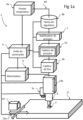
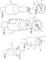
- a handling system 2 according to one embodiment of the invention, is illustrated.
- the handling system 2 is in particular configured for gripping and placing an object 3 without coming into direct contact with the object.
- the handling system 2 according to embodiments of the invention is configured for handling small objects, in particular objects having a mass of less than 20 grams, or even less than 10 grams.
- the handling system 2 according to embodiments of the invention is very advantageously configured for handling very small objects and in particular objects having a mass of less than 1 g up to 0.01 milligrams.
- the size of the handling tool has an important consequence. Indeed, the smaller the size of the tool, the more versatility there is in the use of the tool and in particular for the placement of products in restricted spaces, restricted openings and other constraints on the movement of a tool relative to other tools or parts of the product in which the components are assembled.
- a reduction in the size and mass of the tool allows for faster movement since the inertia of the tool is reduced, thus increasing the handling performance of the tool, for example for the assembly of components.
- the contactless handling system 2 comprises a control unit 4, a suction device 6, and a contactless handling tool 8.
- the suction device comprises a suction pump 6a coupled to the handling tool by a channel 6d for sucking a fluid, in particular a gas, through the contactless handling tool.
- the suction device may further comprise a control valve 6b and sensors, in particular a pressure sensor 5a and a flow sensor 5b.
- the control unit 4 comprises a power supply 9 and a control circuit with a microprocessor for controlling an ultrasonic generator in the handling tool as will be described in more detail below.
- the control unit may also be connected to the suction system, in particular the suction pump 6a and/or the control valve 6b. The control unit makes it possible in particular to control the gripping and release of the object 3 by the contactless handling tool 8.
- control unit 4 is illustrated as being a single control unit but in the case of the invention it is of course possible to have several control units which can be connected together for the control of the various devices such as the suction device 6, the contactless handling tool 8 and a placement table 11 on which the object 3 is placed.
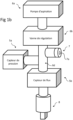
- the suction device 6 may comprise the suction pump 6a connected to the control valve 6b as well as a pressure stabilizer 7 and one/or more sensors, in particular a pressure sensor 5a and a flow sensor 5b.
- the control valve 6b may comprise a proportional solenoid valve which, depending on the pressure measured by the pressure sensor 5a (which may be between 0.01 kPa and 100 kPa) may be configured to maintain the underpressure for suction at a constant or essentially constant level in order to control the suspension distance ds between the gripping face 29 and the object 3. Indeed, the pressure level is influenced by the distance between the object 3 and the gripping face 29.
- a very low pressure implies that the distance separating the object from the gripping face is too small and that there is a risk of contact, while a too high pressure level (a low suction underpressure) indicates that the distance is too great and that there is a risk of release of the object 3.
- the underpressure level measured by the pressure sensor 5a makes it possible to provide in real time the pressure measurement to the control unit 4 which adjusts the solenoid valve to keep the pressure constant.
- the flow sensor 5b may also be used alone or in conjunction with the pressure sensor 5a to determine the presence of a gap between the object and the gripping face. If the object 3 is in contact with the gripping face 29 of the head 28, the air flow through the nozzles 32 may be stopped or very low, while a very high flow indicates that the object is no longer being gripped. The magnitude of the flow within a range of predetermined values can be used to indicate the presence of a gap confirming that the object is gripped by the tool.
- control of the distance between the object 3 and the gripping face 29 of the head 28, can be carried out by controlling the power of the ultrasonic transducer 10, and therefore the repulsive force, alone or jointly with a control of the suction by the suction system as described above.
- the pressure stabilizer 7 can be used to set a safety threshold of the underpressure in order to prevent the underpressure from becoming too high, in particular to avoid clogging the nozzles or the suction channels in the event of contact between the gripping face 29 and the object. It can therefore be adjusted to avoid damage to the object or the tool, in particular to avoid the introduction of parts of the object into the nozzles and suction channels.
- the pressure stabilizer can therefore be used by the control tool to set a pressure threshold permitted by the solenoid valve.
- the pressure stabilizer comprises or is constituted by a resistive orifice 7a which is configured to provide a greater airflow resistance than the suction channel 30 with the nozzles 32, in particular an airflow resistance at least twice, preferably at least three times, preferably at least four times greater than the airflow resistance generated by the suction channel 30 together with the nozzle(s) 32.
- the resistive orifice decreases the slope of increase of the underpressure (i.e. the slope of decrease of the pressure) as a function of the inverse of the distance of the object 3 from the gripping face 29, while allowing the suction system to provide sufficient suction for levitation of the object. This reduces the risk of the object being pinned against the gripping face, and in the event of pinning, reduces the suction force on the object.
- the resistive orifice may for example have a cross-sectional area of half or less the cross-sectional area of the nozzles 32.
- the pressure stabilizer may include a valve fluidly connected to the suction channel on one side and to ambient air on the other side, the valve opening the connection when the pressure decreases below a predetermined threshold configured to allow ambient air to enter the suction channel to increase the pressure (decrease the underpressure).
- a handling system may also include the control of a placement table 11 on which the object 3 is grasped and/or placed.
- a placement table 11 on which the object 3 is grasped and/or placed.
- the placement table 11 is controlled in its movement in the horizontal plane, in particular in translation along the two orthogonal axes 13a but possibly also in rotation, while the handling tool 8 is controlled only in vertical translation and possibly in rotation about the vertical axis 13b, in order to accelerate the grasping/placing process.
- the handling tool 8 can be controlled in vertical translation and also in translation along the horizontal axes in a direction opposite to the translation direction of the table to increase the relative speed between the table 11 and the tool 8.
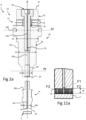
- the suction system comprises a suction channel 30 passing through the handling tool 8, coupled at one end 21 to the suction device 6 and opening at the other end 29 via one or more suction nozzles 32.
- the suction device comprises a connector 6e, for example in the form of a cap mounted on the end 21 of the transducer and comprising a seal 35, for example comprising an O-ring, encircling the rear body 22 of the transducer.
- the connector 6e comprises an inlet, for example in the form of a spout 37, for connecting a hose connected to the suction pump.
- the ultrasonic transducer 10 comprises a vibration generator 12 and a transmission device 18 coupled to the generator 12.
- the generator 12 comprises a stack of piezoelectric elements 14, preferably ceramic piezoelectric rings, sandwiched between a rear body 22 and a front body 24 of the device.
- transmission 18 A prestressing member 20, for example in the form of a screw, passes through central orifices 16 of the piezoelectric rings 14.
- the prestressing member is configured to apply a tensile force between the rear body 22 and the front body 24 leading to a compression force acting on the stack of piezoelectric rings sandwiched between these two bodies.
- the ultrasonic transducer 10 comprises two ceramic piezoelectric rings sandwiched between a rear body 22 and a front body 24 of the transmission device 18. This makes it possible to operate at very high frequency in a very compact configuration.
- the generator advantageously comprises a stack of two to six ceramic piezoelectric rings 14, the piezoelectric rings at the axial ends being oriented so that the neutral electrodes are oriented respectively towards the rear body 22 and the front body 24.
- the head 28 comprises a terminal portion 28a with a gripping face 29 forming the gripping face placed opposite the object 3 to be gripped.
- the terminal portion 28a comprises the suction nozzles 32 connected to the suction channel 30 and which open onto the gripping face 29.
- the ultrasonic waves generated by the generator 12 are emitted by the gripping face 29.
- the ultrasonic waves generate an overpressure relative to the general ambient pressure, creating a repulsive force F2 on the object 3, while the suction of fluid by the suction nozzle 32 generates an underpressure relative to the general ambient pressure, creating an attractive force F1 on the object 3.
- the suction force F1 increases as the distance between the object and the gripping face 29 decreases.
- the repulsive force F1 generated by the ultrasound increases as the distance between the object and the gripping face 29 decreases.
- the equilibrium distance d s between repulsive and attractive forces depending on the mass and the surface of the object is typically between 1 ⁇ m and 80 ⁇ m.
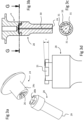
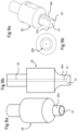
- the head 28 of the transmission device 18 can advantageously be in the form of a part separable from the front body 24, as illustrated. in the Figures 2a-9 .
- This allows the head 28 to be changed depending on the object 3 to be handled.
- a grip such as a flat 39, allows the head to be unscrewed and screwed to the front body.
- the overpressure generated by the near-field ultrasound preferably has an amplitude characteristic that is essentially constant over the entire gripping face 29 in order to ensure that the surface of the object 3 facing the gripping face 29 is stabilized in a position that is essentially parallel to this gripping face 29. This results in lateral stability, leading to centering of the object relative to the axis A of the handling tool, as well as stability against rotation of the object about an axis orthogonal to the axis A.
- the ultrasonic transducer 10 comprises a height h between the end corresponding to the reflecting face 21 of the rear body 22 and the end corresponding to the gripping face 29, essentially equivalent to a half-wavelength ⁇ /2 of the ultrasound generated inside the ultrasonic transducer 10 at the fundamental frequency.
- the wavelength of the ultrasound generated in the transducer depends on the materials forming the transducer, since the wavelength depends on the speed of sound in the medium concerned.
- the materials forming the transducer typically comprise aluminum or titanium (or magnesium) alloys for the front body and the head, steel for the rear body (which reflects the waves), and ceramic for the piezoelectric elements.
- the speed of sound in aluminum is about 6200 m/s, while the speed of sound in air is about 343 m/s.
- the height h may be in a range of 80% to 140% of said half-wavelength ⁇ /2 at the fundamental frequency, in particular in a range of 90% to 110% of said half-wavelength ⁇ /2 at the fundamental frequency.
- a sonotrode is coupled to the transducer, the sonotrode corresponding to at least half a wavelength (sometimes more) (at the fundamental frequency) and the transducer corresponding to at least half a wavelength (at the fundamental frequency), the tools of the prior art having a length between ends of at least one wavelength (at the fundamental frequency) of the ultrasound generated.
- the bulkiness of such tools for applications in tight spaces, in particular for handling very small components (in particular having masses of less than 10 gm, or even less than 1 gm) is a drawback and may, depending on the application, make the use of such tools impossible.
- the operational frequency of known devices corresponds to the fundamental frequency of the transducer, since the amplitude of the generated ultrasound is maximum at the fundamental frequency.
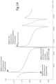
- FIG 14 shows the impedance of the ultrasonic generator for a transducer having approximately half a wavelength at the fundamental frequency f0.
- the operating frequency of the transducer corresponds to the first harmonic frequency f1 of the transducer. It has been found by the inventors that, surprisingly, it is more advantageous to configure the device to work at a frequency regime corresponding to the first harmonic f1 than to the fundamental frequency. Compared to operation at the fundamental frequency, the higher frequency of the oscillations of the first harmonic coupled with an amplitude of the oscillations at the gripping face 29, certainly lower, but still sufficiently large, makes it possible to improve the gripping stability and to provide an optimal ratio between the thrust force and the stability. Indeed, it has been found that one of the sources of instability, in particular for small objects such as millimeter or micrometer objects, is the large amplitude of the oscillations at the fundamental frequency of the transducer.
- an operation of the handling tool at the first harmonic frequency of the transducer generates higher order deformations (than at the fundamental frequency) at the gripping face 29 which contribute to a more uniform distribution of the ultrasound profile in the near field and consequently a more uniform repulsive force, thus contributing to better gripping stability of the object.
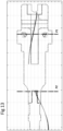
- FIG 13 illustrates the profile of the amplitude of a wave as a function of the axial position in the tool for an operation at the first harmonic frequency of the transducer (the height of the transducer having approximately half a wavelength ⁇ /2 of the ultrasound at the fundamental frequency).
- the fundamental frequency there is only one nodal plane (not illustrated), namely a plane where the amplitude of the wave in the transducer is essentially zero.
- the first harmonic frequency there are two nodal planes P1 , P2 , the first P1 towards the rear of the transducer and the second P2 towards the head of the transducer.
- transducer fixing plane close to or at the first nodal plane P1
- coupling interface 28b between the head 28 and the front body 24 close to or at the second nodal plane P2. This helps reduce transducer wear by reducing micro-friction losses at the interface with the head, and at the same time improve performance (i.e. increase ultrasound power) by reducing energy transmission losses.
- a handling device comprising a transducer configured to operate at the first harmonic frequency f1 is most advantageous for a half wavelength high transducer, but can also be implemented with a one wavelength high transducer within the scope of this invention.
- the ratios between the successive diameters D1, D2, D3, D4, D5 in the decreasing direction may follow the above relationships, the subsequent ones being between max 6 and min 1.1.
- the non-contact handling system in order to reduce the size of the tool, is configured to generate ultrasound in a frequency range of 30 to 500 kHz, preferably between 40 and 300 kHz depending on the size of the object to be handled.
- the height of the tool and the frequency used can be defined depending on the object to be handled. As illustrated in the figure 12b , the smaller the object, the lower the tool height and the higher the frequency can be.
- transducers typically operate in the range of 20 to 40 kHz, whereas in the present invention the combination of a high frequency such as 80 kHz and a tool having a half-wavelength height of about ⁇ /2 of the fundamental frequency allows the height of the handling tool to be reduced by 4 to 8 times compared to conventional tools.
- working with near-field ultrasound for the repulsion force allows the suction force to be reduced as well as the power required to generate the ultrasound to be reduced.
- a fastening element such as a fastening flange 24b, may advantageously be disposed at or near the position of the first nodal plane P1 for securing the tool to a robot arm or other machine member for moving the handling tool.
- the fastening element 24b may advantageously comprise a damping coupling to the body 24, configured to dampen residual vibrations in the nodal plane P1.
- the suction channel 30, in one embodiment, can advantageously be arranged along the central axis A of the handling tool, the channel having a section 30b passing through the front body and a section 30a passing through the screw 20 for coupling to the suction device 6.
- a handling tool of low height for example less than 60 mm in height
- the channel it is also possible to arrange the channel differently in the body of the handling tool in a non-central manner with a radial inlet in the body of the tool, the critical function of the channel being the arrangement of the suction nozzle or nozzles 32 at the gripping face 29 of the head 28.
- the tool comprises a suction nozzle opening onto the gripping face, said suction nozzle being centered on the gripping face.
- the tool comprises a plurality of suction nozzles opening onto the gripping face, said suction nozzles being arranged for example around the center of the gripping face.
- suction nozzles are arranged for example around the center of the gripping face.
- a groove 32a may advantageously be arranged in the gripping face 29 at the position of the nozzles 32 so as to better distribute the pressure of the flow of gas sucked around the center of the gripping face. This avoids too strong a localization of the underpressure around the nozzles 32.
- An example is illustrated in the Figure 7a, 7b .
- Still other configurations can be implemented depending on the geometry of the object to be grasped and the hydrodynamic flow of fluid around the object to be grasped.
- the nozzles are configured to provide a pressure profile to attract the object towards the central axis A of the transmission device in order to laterally stabilize the object relative to the grasping face.
- the head 28 may include an end portion 28a configured for suspension of a drop of liquid, the nozzle or nozzles being configured to create a flow of air or gas around the drop controlling the substantially spherical shape. of the drop, and to arrange on the gripping face 29 a hydrophobic layer to repel the drop when it is very close or comes into accidental contact with the gripping face.
- the gripping face 29 of the nozzle has a shape that matches the shape of the object 3, when there is a gripping operation, especially of a small object, the face of the tool 28 may not be aligned about the vertical axis with the object 3.
- the gripping face approaches the object 3, there is self-centering of the object with the gripping face.
- the objects are not identical and have tolerances, or the tool is used for objects in a range of shape and size where the self-centering effect may not work.
- the gripping face 29 comprises a sharp corner 29a and several other rounded corners, namely less sharp than the reference corner 29a.
- the reference corner 29a serves as an alignment reference with a corner of the object to be gripped, so as to ensure good positioning relative to the gripping face.
- the head 28 and the front body 24c include complementary fastening elements in the form of a bayonet fastening system as illustrated in the Figures 3a to 3d .
- the bayonet fixing system comprising lugs 31 on one of the parts inserting into a complementary groove 33 of the other part, as illustrated in the Figures 3a to 3d .
- the bayonet attachment allows a rapid change of the head, and moreover ensures a precise angular orientation (around the central axis A) of the head relative to the front body 24 of the handling tool.
- the head may, in certain variants, comprise a non-axisymmetric gripping face, for example square (see figure 9 ), rectangular (see Figures 4 to 5b ), oval, polygonal, or other shapes depending on the object to be manipulated.
- the head 28, in a variant, can also be fixed to the front body 24 by means of a threaded coupling.
- Other fixing means known per se, can also be used in the tool according to the invention.
- the handling tool may advantageously comprise a set of several interchangeable heads of different dimensions or shapes to allow the head to be changed depending on the object to be handled. It should be noted, however, that for certain applications, the front body and the head may be integral in the form of a single piece.
- control unit 4 and the generator 12 may be configured to generate vibrations at an anti-resonant frequency f1' of the first harmonic frequency, namely at a forced frequency close to the resonant frequency f1 of the first harmonic frequency.
- figure 14 graphically shows an electrical impedance curve as a function of the frequency of the ultrasonic generator, illustrating a minimum impedance point of the resonant regime f1 and a maximum impedance point of the anti-resonant regime f1' (forced regime).
- the points f1 and f1' are very close in frequency and are associated, the minimum impedance peak being followed by a maximum impedance peak before the impedance decreases to the next harmonic.
- the advantage of this mode of operation and configuration is to create a stable vibration.
- the low impedance requires a high current and induces a strong deformation of the structure which generates a certain instability.
- a high voltage is necessary to obtain the vibration amplitude required to generate the ultrasound, however with a low current.
- Vibrations in this region are more stable because the structure vibrates in a solid manner leading to better stability in controlling the repulsive force of the generated ultrasound. Indeed, by working on forced vibrations, one can more easily vary and control the repulsive force of the ultrasound in the near field.
- An advantage of a system working with forced vibrations is that the gripping surface 29 vibrates with greater flatness than for a resonant regime, which can improve gripping stability due to the more flat repulsive wave pressure.
- the non-contact handling system may further comprise an electrical discharge device 40 (see figure 2d and 2e) in order to eliminate electrostatic charges from the objects.
- the electric discharge device 40 can be separate from the handling tool 8 (figure 2e), or integrated into the handling tool ( figure 2d ). Removing electrical charges from objects allows for better control of the forces acting on the object, particularly to eliminate forces generated by an electrostatic charge of the object. This can also be very advantageous for controlling the equilibrium distance between the object and the tool's gripping face, thereby increasing the accuracy of gripping and placing the object by the handling system.
- the non-contact handling tool may further comprise a position sensor for measuring the position, and in particular the distance, of the object relative to the gripping face.
- the sensor may be in the form of an optical, inductive, capacitive or Hall effect sensor arranged on the gripping face or around or next to the gripping face.
- the position sensor is arranged in the center of the gripping face, the handling tool comprising a plurality of suction nozzles arranged around the sensor.
- the sensor may be connected to the control circuit of the control unit for controlling the forces acting on the object, in particular the suction force by controlling for example the power of the suction pump or a valve on the suction channel, and/or by controlling the power of the emitted ultrasound.
- the position of the object relative to the gripping face can also be measured using one or more cameras that are not part of the handling tool.
- control of the suspension distance d s can also be carried out without a position sensor according to embodiments, in particular by controlling the suction underpressure, this by controlling the suction pump 6a or the valve 6b, according to the pressure measurement given by the pressure sensor 5a.
- the object 3 can be grasped and handled by being arranged below the gripping face 29, but also above the gripping face, or in any other orientation.
- the vertical direction illustrated in the figures therefore does not necessarily correspond to the direction of the gravity force since the handling tool according to the invention can suspend an object in all orientations due to the self-centering carried out by the suction force relative to the gripping face.
Landscapes
- Engineering & Computer Science (AREA)
- Mechanical Engineering (AREA)
- Robotics (AREA)
- Manipulator (AREA)
Claims (15)
- - Handhabungswerkzeug (8) zum berührungslosen Greifen eines Objekts (3), wobei das Werkzeug einen Ultraschallwandler (10), der so konfiguriert ist, dass er Ultraschall aussendet, der in einem Nahfeldbereich der Greiffläche eine Überdruckwelle bildet, und ein Fluidansaugsystem umfasst, das so konfiguriert ist, dass es ein Fluid zur Greiffläche hin ansaugt, in dem Nahfeldbereich eine Unterdruckwelle bildet, dadurch gekennzeichnet, dass der Ultraschallwandler so konfiguriert ist, dass er mit einer Frequenz arbeitet, die der ersten resonanten harmonischen Frequenz des Wandlers oder der ersten antiresonanten harmonischen Frequenz des Wandlers entspricht.
- - Berührungsloses Handhabungswerkzeug nach Anspruch 1, dadurch gekennzeichnet, dass sich der Ultraschallwandler (10) zwischen einer reflektierenden Fläche und einer Greiffläche erstreckt und eine zwischen der Greiffläche und der reflektierenden Fläche definierte Höhe (h) aufweist, die in einem Bereich von 80% bis 140% einer halben Wellenlänge λ/2 des in dem Wandler erzeugten Ultraschalls liegt.
- - Berührungsloses Handhabungswerkzeug nach Anspruch 1 oder 2, dadurch gekennzeichnet, dass das Flüssigkeitssaugsystem mindestens einen Flüssigkeitssaugkanal (30) umfasst, der im Ultraschallwandler angeordnet ist, wobei der Saugkanal eine oder mehrere Saugdüsen umfasst, die in die Greiffläche münden.
- - Berührungsloses Handhabungswerkzeug nach einem der vorhergehenden Ansprüche, dadurch gekennzeichnet, dass der Ultraschallwandler einen Ultraschallgenerator (12) und eine mit dem Generator gekoppelte Übertragungsvorrichtung (18) für den Ultraschall umfasst, wobei die Übertragungsvorrichtung einen Frontkörper (24) umfasst, der mit einem Befestigungselement (24b) für das Werkzeug versehen ist, das auf der Höhe einer ersten Knotenebene (P1) der Ultraschallwellen angeordnet ist, die im Wandler mit einer Frequenz erzeugt werden, die der ersten resonanten harmonischen Frequenz f1 des Wandlers entspricht, oder mit einer Frequenz, die der ersten antiresonanten harmonischen Frequenz f1' des Wandlers entspricht.
- - Berührungsloses Handhabungswerkzeug nach einem der vorhergehenden Ansprüche, dadurch gekennzeichnet, dass der Ultraschallwandler einen Kopf (28) umfasst, der durch eine Befestigungsvorrichtung austauschbar mit einem Vorderkörper der Übertragungsvorrichtung gekoppelt ist, wobei die Greiffläche auf dem Kopf angeordnet ist, eine zweite Knotenebene der Ultraschallwellen, die im Wandler bei einer Frequenz erzeugt werden, die der ersten resonanten harmonischen Frequenz f1 des Wandlers entspricht, oder bei einer Frequenz, die der ersten antiresonanten harmonischen Frequenz fl' des Wandlers entspricht.
- - Berührungsloses Handhabungswerkzeug nach einem der vorhergehenden Ansprüche, dadurch gekennzeichnet, dass der Frontkörper mindestens zwei aufeinanderfolgende Durchmesserreduzierungen D1, D2, D3 in der Richtung vom Ultraschallgenerator (12) zur Greiffläche (29) aufweist, wobei die Verhältnisse zwischen den aufeinanderfolgenden Durchmessern D1, D2, D3 in dieser Richtung in einem Bereich liegen :- für D1/D2 zwischen max 2,6 und min 1,1- für D2/D3 zwischen max 6 und min 1,1und für jede weitere Reduzierung zwischen max zwischen max 6 und min 1,1.
- - Berührungsloses Handhabungswerkzeug nach einem der vorhergehenden Ansprüche, dadurch gekennzeichnet, dass die Greiffläche in einem Bereich von 0,01 bis 650 mm2 liegt und eben ist oder eine gekrümmte, z. B. konkave, Form hat, die so konfiguriert ist, dass sie mit einem Teil der Oberfläche des zu greifenden Objekts übereinstimmt.
- - Berührungsloses Handhabungssystem mit einem berührungslosen Handhabungswerkzeug nach einem der vorhergehenden Ansprüche, einer Steuereinheit (4), die mit einem Ultraschallgenerator des Ultraschallwandlers verbunden ist, und einer Saugvorrichtung (6) mit einer Saugpumpe, die mit einem Fluidansaugkanal verbunden ist, wobei die Steuereinheit und der Ultraschallwandler so konfiguriert sind, dass sie Ultraschall in dem Wandler bei einer ersten resonanten harmonischen Frequenz des Wandlers oder bei einer ersten antiresonanten harmonischen Frequenz des Wandlers erzeugen.
- - Berührungsloses Handhabungssystem nach Anspruch 8, dadurch gekennzeichnet, dass die Saugvorrichtung ein Magnetventil (6b) und einen Drucksensor (5a) umfasst, die mit der Steuereinheit (4) verbunden sind, wobei das Magnetventil durch den vom Drucksensor gemessenen Druck reguliert wird, um einen Aufhängeabstand ds des Objekts von der Greiffläche zu steuern.
- - Berührungsloses Handhabungssystem nach Anspruch 8 oder 9, dadurch gekennzeichnet, dass es einen Druckstabilisator (7) umfasst, der fluidisch mit dem Saugkanal gekoppelt ist, um ein Überschreiten einer Unterdruckschwelle zu begrenzen, um ein zu starkes Saugen zu vermeiden.
- - Berührungsloses Handhabungssystem nach dem vorhergehenden Anspruch, dadurch gekennzeichnet, dass der Druckstabilisator eine Widerstandsöffnung (7a) umfasst oder aus einer solchen besteht, die so konfiguriert ist, dass sie einen Luftstromwiderstand liefert, der größer ist als der Saugkanal (30), insbesondere einen Luftstromwiderstand, der mindestens doppelt so groß, vorzugsweise mindestens dreimal so groß, vorzugsweise mindestens viermal so groß ist wie der Luftstromwiderstand, der durch den Saugkanal (30) zusammen mit der Düse oder den Düsen (32) erzeugt wird.
- - Verfahren zur berührungslosen Handhabung eines Objekts, umfassend :- Bereitstellung eines berührungsloses Handhabungssystems nach einem der Ansprüche 8 bis 11 ;- Aktivierung der Saugpumpe zum Erzeugen einer Saugkraft und des Ultraschallgenerators zum Erzeugen einer Abstoßungskraft in Bezug auf die Greiffläche, wobei der Ultraschallgenerator von der Steuereinheit gesteuert wird, um Ultraschall in dem Wandler bei einer ersten resonanten harmonischen Frequenz des Wandlers oder einer ersten antiresonanten harmonischen Frequenz zu erzeugen ;- Platzierung der Greiffläche des Handhabungsgeräts in einem Abstand im Bereich des 0,5- bis 6-fachen des Aufhängeabstands ds vor einer Oberfläche des Objekts ;- Aufhängen des Objekts in einem von Null verschiedenen Aufhängeabstand gegenüber der Greiffläche durch Steuerung der Saugvorrichtung und/oder des Ultraschallgenerators, wobei der Aufhängeabstand so gesteuert wird, dass er sich in einem Nahfeldbereich des Ultraschalls befindet.
- - Verfahren zur berührungslosen Handhabung nach Anspruch 12, dadurch gekennzeichnet, dass die Saugvorrichtung ein Magnetventil (6b) und einen Drucksensor (5a) umfasst, die mit der Steuereinheit (4) verbunden sind, wobei das Magnetventil durch den vom Drucksensor gemessenen Druck reguliert wird, um einen Aufhängeabstand ds des Objekts von der Greiffläche zu steuern.
- - Verfahren zur berührungslosen Handhabung nach Anspruch 12 oder 13, dadurch gekennzeichnet, dass die Saugvorrichtung einen Druckstabilisator (7) umfasst, der fluidisch mit dem Saugkanal gekoppelt ist, wobei der Stabilisator eine Überschreitung einer Unterdruckschwelle begrenzt, um ein Ansaugen von Fremdmaterial aus dem Objekt in Düsen oder in den Saugkanal zu verhindern.
- - Verfahren zur berührungslosen Handhabung nach einem der Ansprüche 12 bis 14, dadurch gekennzeichnet, dass die Saugvorrichtung einen Strömungssensor (5b) umfasst, der die Luftströmung in dem Saugkanal misst, der das Werkzeug mit der Saugpumpe verbindet, um eine Berührung des Objekts mit der Greiffläche zu erfassen oder um eine zu hohe Strömung zu erfassen, die anzeigt, dass das Objekt nicht mehr mit dem Werkzeug in Eingriff ist.
Applications Claiming Priority (1)
| Application Number | Priority Date | Filing Date | Title |
|---|---|---|---|
| PCT/EP2018/064463 WO2019228641A1 (fr) | 2018-06-01 | 2018-06-01 | Dispositif pour manipulation d'objet sans contact |
Publications (2)
| Publication Number | Publication Date |
|---|---|
| EP3802018A1 EP3802018A1 (de) | 2021-04-14 |
| EP3802018B1 true EP3802018B1 (de) | 2025-01-22 |
Family
ID=62495806
Family Applications (1)
| Application Number | Title | Priority Date | Filing Date |
|---|---|---|---|
| EP18728880.8A Active EP3802018B1 (de) | 2018-06-01 | 2018-06-01 | Vorrichtung zur berührungslosen objekthandhabung |
Country Status (4)
| Country | Link |
|---|---|
| US (1) | US20210213624A1 (de) |
| EP (1) | EP3802018B1 (de) |
| CN (1) | CN112236274A (de) |
| WO (1) | WO2019228641A1 (de) |
Families Citing this family (1)
| Publication number | Priority date | Publication date | Assignee | Title |
|---|---|---|---|---|
| CN112490171B (zh) * | 2020-11-20 | 2023-12-19 | 浙江大学 | 一种基于近场声悬浮原理的盘片非接触吸附装置 |
Family Cites Families (15)
| Publication number | Priority date | Publication date | Assignee | Title |
|---|---|---|---|---|
| DE10121742A1 (de) | 2001-05-04 | 2003-01-23 | Bosch Gmbh Robert | Vorrichtung zum berührungslosen Greifen und Halten eines Gegenstandes |
| US7240679B2 (en) * | 2002-09-30 | 2007-07-10 | Lam Research Corporation | System for substrate processing with meniscus, vacuum, IPA vapor, drying manifold |
| JP4376737B2 (ja) * | 2004-08-31 | 2009-12-02 | 学校法人東京理科大学 | 非接触チャック |
| GB0809243D0 (en) * | 2008-05-21 | 2008-06-25 | Sra Dev Ltd | Improved torsional mode tissue dissector |
| DE102008036805A1 (de) * | 2008-08-07 | 2009-09-24 | Siemens Aktiengesellschaft | Bestückkopf zum Bestücken von Substraten mit Bauelementen, Bestückautomat und Bestückverfahren |
| KR100928674B1 (ko) * | 2009-04-07 | 2009-11-27 | 삼성코닝정밀유리 주식회사 | 비접촉 석션 그립핑 장치 및 이를 갖는 비접촉 석션 그립핑 프레임 |
| CN102490132B (zh) * | 2011-11-25 | 2013-06-19 | 苏州科技学院 | 一种压电超声振动吸附拾取器 |
| US10251657B1 (en) * | 2013-05-02 | 2019-04-09 | University Of Washington Through Its Center For Commercialization | Noninvasive fragmentation of urinary tract stones with focused ultrasound |
| LU92205B1 (en) * | 2013-05-29 | 2014-12-01 | Iee Sarl | Transducer arrangement for measuring load variations |
| US9504471B2 (en) * | 2013-09-25 | 2016-11-29 | Cybersonics, Inc. | Ultrasonic generator systems and methods |
| WO2016013338A1 (ja) * | 2014-07-24 | 2016-01-28 | オリンパス株式会社 | 超音波処置システム、エネルギー源ユニット、及び、エネルギー源ユニットの作動方法 |
| JP6135626B2 (ja) * | 2014-09-19 | 2017-05-31 | 村田機械株式会社 | ワークの非接触保持装置 |
| EP3199250B1 (de) * | 2014-09-22 | 2019-09-11 | Olympus Corporation | Schwingungserzeugende einheit, schwingungskomponenteneinheit und vorrichtung zur verarbeitung von ultraschallwellen |
| TWI635883B (zh) * | 2017-08-30 | 2018-09-21 | 中原大學 | 壓電式超音波熱電療系統 |
| CN107676127B (zh) * | 2017-10-20 | 2018-12-25 | 四川大学 | 孔内变频振动增透瓦斯抽采方法及装置 |
-
2018
- 2018-06-01 EP EP18728880.8A patent/EP3802018B1/de active Active
- 2018-06-01 WO PCT/EP2018/064463 patent/WO2019228641A1/fr not_active Ceased
- 2018-06-01 US US17/059,943 patent/US20210213624A1/en not_active Abandoned
- 2018-06-01 CN CN201880094108.8A patent/CN112236274A/zh active Pending
Also Published As
| Publication number | Publication date |
|---|---|
| EP3802018A1 (de) | 2021-04-14 |
| US20210213624A1 (en) | 2021-07-15 |
| CN112236274A (zh) | 2021-01-15 |
| WO2019228641A1 (fr) | 2019-12-05 |
Similar Documents
| Publication | Publication Date | Title |
|---|---|---|
| EP3548229B1 (de) | Vorrichtung zur berührungslosen objekthandhabung | |
| TWI486239B (zh) | A non-contact holding device, a transfer device, and a non-contact holding method | |
| EP1124674B1 (de) | Verfahren und vorrichtung zum spalten einer platte, aus insbesondere halbleitermaterial, in zwei dünneren platten | |
| FR3051701A1 (fr) | Dispositif de prehension a membrane et ventouse | |
| EP2091663A1 (de) | Ultraschallflüssigkeitszerstäuber | |
| EP3802018B1 (de) | Vorrichtung zur berührungslosen objekthandhabung | |
| FR3100470A1 (fr) | Structure porteuse pour un dispositif de manutention, procédé de production d'une structure porteuse | |
| EP3059300B1 (de) | Vorrichtung zur manipulation von biologischen zellen mithilfe einer schwingenden halterung | |
| FR2968735A1 (fr) | Micro-generateur fluidique de jets synthetiques. | |
| FR2910826A1 (fr) | Dispositif pour la production de vibrations ultrasoniques | |
| EP1520669A1 (de) | Verfahren zum Trennen von Platten, die miteinander geklebt sind und eine gestapelte Struktur bilden | |
| EP3194310A1 (de) | Vorrichtung zur trennung von kleinen losen objekten | |
| FR3074710B1 (fr) | Dispositif de prehension a membrane et ventouse | |
| Takasaki et al. | Non-contact ultrasonic support of minute objects | |
| FR3100004A1 (fr) | Dispositif de préhension | |
| EP3937215B1 (de) | Positionierungsmaske, system und verfahren zur herstellung einer optoelektrischen vorrichtung | |
| EP3774207B1 (de) | Greifvorrichtung | |
| FR3073761A1 (fr) | Outillage ameliore pour la fabrication additive | |
| EP4497555A1 (de) | Greiforgan für vakuumbehälter | |
| CH719654A2 (fr) | Procédé et équipement d'usinage correctif de pièces microtechniques. | |
| FR3155450A1 (fr) | Dispositif de préhension pour élément de faible épaisseur, système et procédé associés | |
| WO2011012517A2 (fr) | Sonotrode a gorge et machine a usinage ultrasonore integrant la sonotrode | |
| FR3123343A1 (fr) | Microsystème électromécanique | |
| FR3092513A1 (fr) | Dispositif de préhension à membrane et électroaimants | |
| FR2963741A1 (fr) | Dispositif de maintien par capillarite d'un element comportant au moins une face plane |
Legal Events
| Date | Code | Title | Description |
|---|---|---|---|
| STAA | Information on the status of an ep patent application or granted ep patent |
Free format text: STATUS: UNKNOWN |
|
| STAA | Information on the status of an ep patent application or granted ep patent |
Free format text: STATUS: THE INTERNATIONAL PUBLICATION HAS BEEN MADE |
|
| PUAI | Public reference made under article 153(3) epc to a published international application that has entered the european phase |
Free format text: ORIGINAL CODE: 0009012 |
|
| STAA | Information on the status of an ep patent application or granted ep patent |
Free format text: STATUS: REQUEST FOR EXAMINATION WAS MADE |
|
| 17P | Request for examination filed |
Effective date: 20201218 |
|
| AK | Designated contracting states |
Kind code of ref document: A1 Designated state(s): AL AT BE BG CH CY CZ DE DK EE ES FI FR GB GR HR HU IE IS IT LI LT LU LV MC MK MT NL NO PL PT RO RS SE SI SK SM TR |
|
| AX | Request for extension of the european patent |
Extension state: BA ME |
|
| DAV | Request for validation of the european patent (deleted) | ||
| DAX | Request for extension of the european patent (deleted) | ||
| P01 | Opt-out of the competence of the unified patent court (upc) registered |
Effective date: 20230601 |
|
| GRAP | Despatch of communication of intention to grant a patent |
Free format text: ORIGINAL CODE: EPIDOSNIGR1 |
|
| STAA | Information on the status of an ep patent application or granted ep patent |
Free format text: STATUS: GRANT OF PATENT IS INTENDED |
|
| INTG | Intention to grant announced |
Effective date: 20240816 |
|
| GRAS | Grant fee paid |
Free format text: ORIGINAL CODE: EPIDOSNIGR3 |
|
| GRAA | (expected) grant |
Free format text: ORIGINAL CODE: 0009210 |
|
| STAA | Information on the status of an ep patent application or granted ep patent |
Free format text: STATUS: THE PATENT HAS BEEN GRANTED |
|
| AK | Designated contracting states |
Kind code of ref document: B1 Designated state(s): AL AT BE BG CH CY CZ DE DK EE ES FI FR GB GR HR HU IE IS IT LI LT LU LV MC MK MT NL NO PL PT RO RS SE SI SK SM TR |
|
| REG | Reference to a national code |
Ref country code: GB Ref legal event code: FG4D Free format text: NOT ENGLISH |
|
| REG | Reference to a national code |
Ref country code: CH Ref legal event code: EP |
|
| REG | Reference to a national code |
Ref country code: IE Ref legal event code: FG4D Free format text: LANGUAGE OF EP DOCUMENT: FRENCH |
|
| REG | Reference to a national code |
Ref country code: DE Ref legal event code: R096 Ref document number: 602018078659 Country of ref document: DE |
|
| REG | Reference to a national code |
Ref country code: NL Ref legal event code: MP Effective date: 20250122 |
|
| PG25 | Lapsed in a contracting state [announced via postgrant information from national office to epo] |
Ref country code: NL Free format text: LAPSE BECAUSE OF FAILURE TO SUBMIT A TRANSLATION OF THE DESCRIPTION OR TO PAY THE FEE WITHIN THE PRESCRIBED TIME-LIMIT Effective date: 20250122 |
|
| PG25 | Lapsed in a contracting state [announced via postgrant information from national office to epo] |
Ref country code: RS Free format text: LAPSE BECAUSE OF FAILURE TO SUBMIT A TRANSLATION OF THE DESCRIPTION OR TO PAY THE FEE WITHIN THE PRESCRIBED TIME-LIMIT Effective date: 20250422 |
|
| PG25 | Lapsed in a contracting state [announced via postgrant information from national office to epo] |
Ref country code: FI Free format text: LAPSE BECAUSE OF FAILURE TO SUBMIT A TRANSLATION OF THE DESCRIPTION OR TO PAY THE FEE WITHIN THE PRESCRIBED TIME-LIMIT Effective date: 20250122 |
|
| PG25 | Lapsed in a contracting state [announced via postgrant information from national office to epo] |
Ref country code: PL Free format text: LAPSE BECAUSE OF FAILURE TO SUBMIT A TRANSLATION OF THE DESCRIPTION OR TO PAY THE FEE WITHIN THE PRESCRIBED TIME-LIMIT Effective date: 20250122 |
|
| PGFP | Annual fee paid to national office [announced via postgrant information from national office to epo] |
Ref country code: DE Payment date: 20250618 Year of fee payment: 8 |
|
| PG25 | Lapsed in a contracting state [announced via postgrant information from national office to epo] |
Ref country code: ES Free format text: LAPSE BECAUSE OF FAILURE TO SUBMIT A TRANSLATION OF THE DESCRIPTION OR TO PAY THE FEE WITHIN THE PRESCRIBED TIME-LIMIT Effective date: 20250122 |
|
| REG | Reference to a national code |
Ref country code: LT Ref legal event code: MG9D |
|
| PG25 | Lapsed in a contracting state [announced via postgrant information from national office to epo] |
Ref country code: NO Free format text: LAPSE BECAUSE OF FAILURE TO SUBMIT A TRANSLATION OF THE DESCRIPTION OR TO PAY THE FEE WITHIN THE PRESCRIBED TIME-LIMIT Effective date: 20250422 Ref country code: IS Free format text: LAPSE BECAUSE OF FAILURE TO SUBMIT A TRANSLATION OF THE DESCRIPTION OR TO PAY THE FEE WITHIN THE PRESCRIBED TIME-LIMIT Effective date: 20250522 |
|
| REG | Reference to a national code |
Ref country code: AT Ref legal event code: MK05 Ref document number: 1761138 Country of ref document: AT Kind code of ref document: T Effective date: 20250122 |
|
| PG25 | Lapsed in a contracting state [announced via postgrant information from national office to epo] |
Ref country code: HR Free format text: LAPSE BECAUSE OF FAILURE TO SUBMIT A TRANSLATION OF THE DESCRIPTION OR TO PAY THE FEE WITHIN THE PRESCRIBED TIME-LIMIT Effective date: 20250122 |
|
| PG25 | Lapsed in a contracting state [announced via postgrant information from national office to epo] |
Ref country code: LV Free format text: LAPSE BECAUSE OF FAILURE TO SUBMIT A TRANSLATION OF THE DESCRIPTION OR TO PAY THE FEE WITHIN THE PRESCRIBED TIME-LIMIT Effective date: 20250122 Ref country code: PT Free format text: LAPSE BECAUSE OF FAILURE TO SUBMIT A TRANSLATION OF THE DESCRIPTION OR TO PAY THE FEE WITHIN THE PRESCRIBED TIME-LIMIT Effective date: 20250522 |
|
| PG25 | Lapsed in a contracting state [announced via postgrant information from national office to epo] |
Ref country code: GR Free format text: LAPSE BECAUSE OF FAILURE TO SUBMIT A TRANSLATION OF THE DESCRIPTION OR TO PAY THE FEE WITHIN THE PRESCRIBED TIME-LIMIT Effective date: 20250423 Ref country code: BG Free format text: LAPSE BECAUSE OF FAILURE TO SUBMIT A TRANSLATION OF THE DESCRIPTION OR TO PAY THE FEE WITHIN THE PRESCRIBED TIME-LIMIT Effective date: 20250122 |
|
| PG25 | Lapsed in a contracting state [announced via postgrant information from national office to epo] |
Ref country code: AT Free format text: LAPSE BECAUSE OF FAILURE TO SUBMIT A TRANSLATION OF THE DESCRIPTION OR TO PAY THE FEE WITHIN THE PRESCRIBED TIME-LIMIT Effective date: 20250122 |
|
| PG25 | Lapsed in a contracting state [announced via postgrant information from national office to epo] |
Ref country code: SE Free format text: LAPSE BECAUSE OF FAILURE TO SUBMIT A TRANSLATION OF THE DESCRIPTION OR TO PAY THE FEE WITHIN THE PRESCRIBED TIME-LIMIT Effective date: 20250122 |
|
| PG25 | Lapsed in a contracting state [announced via postgrant information from national office to epo] |
Ref country code: SM Free format text: LAPSE BECAUSE OF FAILURE TO SUBMIT A TRANSLATION OF THE DESCRIPTION OR TO PAY THE FEE WITHIN THE PRESCRIBED TIME-LIMIT Effective date: 20250122 |
|
| PG25 | Lapsed in a contracting state [announced via postgrant information from national office to epo] |
Ref country code: DK Free format text: LAPSE BECAUSE OF FAILURE TO SUBMIT A TRANSLATION OF THE DESCRIPTION OR TO PAY THE FEE WITHIN THE PRESCRIBED TIME-LIMIT Effective date: 20250122 |
|
| PG25 | Lapsed in a contracting state [announced via postgrant information from national office to epo] |
Ref country code: IT Free format text: LAPSE BECAUSE OF FAILURE TO SUBMIT A TRANSLATION OF THE DESCRIPTION OR TO PAY THE FEE WITHIN THE PRESCRIBED TIME-LIMIT Effective date: 20250122 |
|
| PG25 | Lapsed in a contracting state [announced via postgrant information from national office to epo] |
Ref country code: EE Free format text: LAPSE BECAUSE OF FAILURE TO SUBMIT A TRANSLATION OF THE DESCRIPTION OR TO PAY THE FEE WITHIN THE PRESCRIBED TIME-LIMIT Effective date: 20250122 Ref country code: CZ Free format text: LAPSE BECAUSE OF FAILURE TO SUBMIT A TRANSLATION OF THE DESCRIPTION OR TO PAY THE FEE WITHIN THE PRESCRIBED TIME-LIMIT Effective date: 20250122 |
|
| REG | Reference to a national code |
Ref country code: DE Ref legal event code: R097 Ref document number: 602018078659 Country of ref document: DE |
|
| PG25 | Lapsed in a contracting state [announced via postgrant information from national office to epo] |
Ref country code: RO Free format text: LAPSE BECAUSE OF FAILURE TO SUBMIT A TRANSLATION OF THE DESCRIPTION OR TO PAY THE FEE WITHIN THE PRESCRIBED TIME-LIMIT Effective date: 20250122 |
|
| PG25 | Lapsed in a contracting state [announced via postgrant information from national office to epo] |
Ref country code: SK Free format text: LAPSE BECAUSE OF FAILURE TO SUBMIT A TRANSLATION OF THE DESCRIPTION OR TO PAY THE FEE WITHIN THE PRESCRIBED TIME-LIMIT Effective date: 20250122 |
|
| PLBE | No opposition filed within time limit |
Free format text: ORIGINAL CODE: 0009261 |
|
| STAA | Information on the status of an ep patent application or granted ep patent |
Free format text: STATUS: NO OPPOSITION FILED WITHIN TIME LIMIT |
|
| REG | Reference to a national code |
Ref country code: CH Ref legal event code: L10 Free format text: ST27 STATUS EVENT CODE: U-0-0-L10-L00 (AS PROVIDED BY THE NATIONAL OFFICE) Effective date: 20251203 |
|
| 26N | No opposition filed |
Effective date: 20251023 |
|
| REG | Reference to a national code |
Ref country code: CH Ref legal event code: H13 Free format text: ST27 STATUS EVENT CODE: U-0-0-H10-H13 (AS PROVIDED BY THE NATIONAL OFFICE) Effective date: 20260127 |
|
| PG25 | Lapsed in a contracting state [announced via postgrant information from national office to epo] |
Ref country code: MC Free format text: LAPSE BECAUSE OF FAILURE TO SUBMIT A TRANSLATION OF THE DESCRIPTION OR TO PAY THE FEE WITHIN THE PRESCRIBED TIME-LIMIT Effective date: 20250122 |
|
| PG25 | Lapsed in a contracting state [announced via postgrant information from national office to epo] |
Ref country code: LU Free format text: LAPSE BECAUSE OF NON-PAYMENT OF DUE FEES Effective date: 20250601 |
|
| GBPC | Gb: european patent ceased through non-payment of renewal fee |
Effective date: 20250601 |
|
| REG | Reference to a national code |
Ref country code: BE Ref legal event code: MM Effective date: 20250630 |