EP3800522B1 - Hilfsvorrichtung mit elektronischem vierwegeventil zur erzielung einer temperaturanstiegs- und -abfallwirkung auf eine komponente einer werkzeugmaschine - Google Patents
Hilfsvorrichtung mit elektronischem vierwegeventil zur erzielung einer temperaturanstiegs- und -abfallwirkung auf eine komponente einer werkzeugmaschine Download PDFInfo
- Publication number
- EP3800522B1 EP3800522B1 EP20196160.4A EP20196160A EP3800522B1 EP 3800522 B1 EP3800522 B1 EP 3800522B1 EP 20196160 A EP20196160 A EP 20196160A EP 3800522 B1 EP3800522 B1 EP 3800522B1
- Authority
- EP
- European Patent Office
- Prior art keywords
- machine tool
- channel
- fluid
- electronic valve
- rear end
- Prior art date
- Legal status (The legal status is an assumption and is not a legal conclusion. Google has not performed a legal analysis and makes no representation as to the accuracy of the status listed.)
- Active
Links
Images




Classifications
-
- F—MECHANICAL ENGINEERING; LIGHTING; HEATING; WEAPONS; BLASTING
- F28—HEAT EXCHANGE IN GENERAL
- F28F—DETAILS OF HEAT-EXCHANGE AND HEAT-TRANSFER APPARATUS, OF GENERAL APPLICATION
- F28F27/00—Control arrangements or safety devices specially adapted for heat-exchange or heat-transfer apparatus
- F28F27/02—Control arrangements or safety devices specially adapted for heat-exchange or heat-transfer apparatus for controlling the distribution of heat-exchange media between different channels
-
- G—PHYSICS
- G05—CONTROLLING; REGULATING
- G05D—SYSTEMS FOR CONTROLLING OR REGULATING NON-ELECTRIC VARIABLES
- G05D23/00—Control of temperature
- G05D23/19—Control of temperature characterised by the use of electric means
- G05D23/1919—Control of temperature characterised by the use of electric means characterised by the type of controller
-
- B—PERFORMING OPERATIONS; TRANSPORTING
- B23—MACHINE TOOLS; METAL-WORKING NOT OTHERWISE PROVIDED FOR
- B23Q—DETAILS, COMPONENTS, OR ACCESSORIES FOR MACHINE TOOLS, e.g. ARRANGEMENTS FOR COPYING OR CONTROLLING; MACHINE TOOLS IN GENERAL CHARACTERISED BY THE CONSTRUCTION OF PARTICULAR DETAILS OR COMPONENTS; COMBINATIONS OR ASSOCIATIONS OF METAL-WORKING MACHINES, NOT DIRECTED TO A PARTICULAR RESULT
- B23Q11/00—Accessories fitted to machine tools for keeping tools or parts of the machine in good working condition or for cooling work; Safety devices specially combined with or arranged in, or specially adapted for use in connection with, machine tools
- B23Q11/14—Methods or arrangements for maintaining a constant temperature in parts of machine tools
- B23Q11/141—Methods or arrangements for maintaining a constant temperature in parts of machine tools using a closed fluid circuit for cooling or heating
-
- B—PERFORMING OPERATIONS; TRANSPORTING
- B23—MACHINE TOOLS; METAL-WORKING NOT OTHERWISE PROVIDED FOR
- B23Q—DETAILS, COMPONENTS, OR ACCESSORIES FOR MACHINE TOOLS, e.g. ARRANGEMENTS FOR COPYING OR CONTROLLING; MACHINE TOOLS IN GENERAL CHARACTERISED BY THE CONSTRUCTION OF PARTICULAR DETAILS OR COMPONENTS; COMBINATIONS OR ASSOCIATIONS OF METAL-WORKING MACHINES, NOT DIRECTED TO A PARTICULAR RESULT
- B23Q11/00—Accessories fitted to machine tools for keeping tools or parts of the machine in good working condition or for cooling work; Safety devices specially combined with or arranged in, or specially adapted for use in connection with, machine tools
- B23Q11/0003—Arrangements for preventing undesired thermal effects on tools or parts of the machine
-
- B—PERFORMING OPERATIONS; TRANSPORTING
- B23—MACHINE TOOLS; METAL-WORKING NOT OTHERWISE PROVIDED FOR
- B23Q—DETAILS, COMPONENTS, OR ACCESSORIES FOR MACHINE TOOLS, e.g. ARRANGEMENTS FOR COPYING OR CONTROLLING; MACHINE TOOLS IN GENERAL CHARACTERISED BY THE CONSTRUCTION OF PARTICULAR DETAILS OR COMPONENTS; COMBINATIONS OR ASSOCIATIONS OF METAL-WORKING MACHINES, NOT DIRECTED TO A PARTICULAR RESULT
- B23Q11/00—Accessories fitted to machine tools for keeping tools or parts of the machine in good working condition or for cooling work; Safety devices specially combined with or arranged in, or specially adapted for use in connection with, machine tools
- B23Q11/10—Arrangements for cooling or lubricating tools or work
-
- B—PERFORMING OPERATIONS; TRANSPORTING
- B23—MACHINE TOOLS; METAL-WORKING NOT OTHERWISE PROVIDED FOR
- B23Q—DETAILS, COMPONENTS, OR ACCESSORIES FOR MACHINE TOOLS, e.g. ARRANGEMENTS FOR COPYING OR CONTROLLING; MACHINE TOOLS IN GENERAL CHARACTERISED BY THE CONSTRUCTION OF PARTICULAR DETAILS OR COMPONENTS; COMBINATIONS OR ASSOCIATIONS OF METAL-WORKING MACHINES, NOT DIRECTED TO A PARTICULAR RESULT
- B23Q11/00—Accessories fitted to machine tools for keeping tools or parts of the machine in good working condition or for cooling work; Safety devices specially combined with or arranged in, or specially adapted for use in connection with, machine tools
- B23Q11/14—Methods or arrangements for maintaining a constant temperature in parts of machine tools
- B23Q11/146—Methods or arrangements for maintaining a constant temperature in parts of machine tools by controlling the temperature of a cutting liquid
-
- F—MECHANICAL ENGINEERING; LIGHTING; HEATING; WEAPONS; BLASTING
- F16—ENGINEERING ELEMENTS AND UNITS; GENERAL MEASURES FOR PRODUCING AND MAINTAINING EFFECTIVE FUNCTIONING OF MACHINES OR INSTALLATIONS; THERMAL INSULATION IN GENERAL
- F16K—VALVES; TAPS; COCKS; ACTUATING-FLOATS; DEVICES FOR VENTING OR AERATING
- F16K31/00—Actuating devices; Operating means; Releasing devices
- F16K31/002—Actuating devices; Operating means; Releasing devices actuated by temperature variation
-
- G—PHYSICS
- G05—CONTROLLING; REGULATING
- G05D—SYSTEMS FOR CONTROLLING OR REGULATING NON-ELECTRIC VARIABLES
- G05D23/00—Control of temperature
- G05D23/19—Control of temperature characterised by the use of electric means
- G05D23/20—Control of temperature characterised by the use of electric means with sensing elements having variation of electric or magnetic properties with change of temperature
-
- F—MECHANICAL ENGINEERING; LIGHTING; HEATING; WEAPONS; BLASTING
- F28—HEAT EXCHANGE IN GENERAL
- F28F—DETAILS OF HEAT-EXCHANGE AND HEAT-TRANSFER APPARATUS, OF GENERAL APPLICATION
- F28F2250/00—Arrangements for modifying the flow of the heat exchange media, e.g. flow guiding means; Particular flow patterns
- F28F2250/08—Fluid driving means, e.g. pumps, fans
Definitions
- the present invention relates to the technology of temperature control of a machine tool, and in particular, to an auxiliary apparatus using a four-way electronic valve to achieve temperature rise and fall effect on a component of a machine tool.
- Taiwanese Patent No. 1593501 discloses a machine tool constant temperature control system and a flow channel switch valve, and it is mainly used to adjust the temperature of a machine tool during its operation in order to improve the machining precision and quality of the machine tool.
- the main technical means adopted to achieve the aforementioned function is to utilize its storage tank, pump, cooling device and flow channel switch valve in order to provide the cooling effect.
- As for the heating function it is further installed with a temperature sensor and a heating device.
- US 2019047104 A1 discloses a thermal stability control system and a control method thereof for a machine tool.
- the control system mainly consists of a machine cooling sub-system composed of a pump, at least a cooling loop and a tank for storing cooling fluid, a cooling fluid cooling and heating sub-system, a heater and a micro controller.
- the cooling fluid cooling and heating sub-system further consists of a condenser, an evaporator, a directional valve, an expansion valve and a compressor.
- the micro controller dominates corresponding operation combinations of turning the heater on or off, enabling or disenabling the cooling fluid cooling and heating sub-system as a heat pump or a cooler by activating or releasing the directional vale, and adjusting the driving frequency of an inverter duty motor to drive the pump to change the flow rate of cooling fluid through the cooling loop according the real time load of the machine tool.
- US 2009/174101 A1 relates to an apparatus for controlling the temperature of molds, which substantially operates as the system known from the US 2019047104 A1 .
- the aforementioned known technique has the drawback of an extremely slow speed of temperature adjustment, and for conditions requiring relatively high temperature adjustment speed, it is insufficient and ineffective.
- such known technique is also associated with the drawback of requiring modification of the original cooling device or storage tank.
- the aforementioned temperature adjustment device requires the modification of the original cooling device or storage tank, leading to increase of cost and the likelihood of machine malfunction and error due to such modification.
- the present invention provides an auxiliary apparatus using a four-way electronic valve to achieve temperature rise and fall effect on a component of a machine tool, such that when the temperature of the component of a machine tool is to be adjusted higher, the auxiliary apparatus of the present invention is able to achieve heating effect, and it does not require the modification of the original cooling device used by the machine tool.
- the present invention is able to provide an additional heating function for a spindle of a machine tool originally equipped with a cooling device while retaining its original cooling function; therefore, it is able to achieve the effect of increasing the temperature of the component of a machine tool when the temperature is to be increased.
- the present invention does not require modification of the cooling device originally used by the machine tool. Consequently, the drawbacks associated with the aforementioned known technique or prior art are overcome.
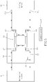
- an auxiliary apparatus 10 using a four-way electronic valve to achieve temperature rise and fall effect on a component of a machine tool is provided, and it is adapted to be connected to pipelines connected to a component of a machine tool and to a cooling device 91.
- the component of the machine tool refers to, such as, a machine tool spindle 81, and the machine tool spindle 81 is mainly used as an example for the illustration of the present invention described in the following.
- the auxiliary apparatus 10 using a four-way electronic valve to achieve temperature rise and fall effect on a component of a machine tool mainly comprises a four-way electronic valve 11, an outflow channel 13, a return fluid incoming channel 15 and a pump 17.
- the four-way electronic valve 11 includes a front end inlet 111, a front end outlet 113, a rear end outlet 115 and a rear end inlet 117.
- the four-way electronic valve 11 is electrically connected to a control source 21 and controlled by the control source 21 to switch between two channel states.
- the control source 21 in this embodiment can be an external box, such as a built-in control box of the machine tool, or an external microcomputer control module.
- the front end inlet 111 is fluidly connected to the rear end outlet 115 but is not fluidly connected to the front end outlet 113
- the rear end inlet 117 is fluidly connected to the front end outlet 113 but is not fluidly connected to the rear end outlet 115.
- the front end inlet 111 When it is under a second channel state, the front end inlet 111 is fluidly connected to the front end outlet 113 but is not fluidly connected to the rear end outlet 115, and the rear end inlet 117 is fluidly connected to the rear end outlet 115 but us not fluidly connected to the front end outlet 113.
- the front end inlet 111 is configured to allow a fluid of the cooling device 91 to enter therein, and the front end outlet 113 is configured to allow the fluid to flow out to the cooling device 91.
- the outflow channel 13 includes one end connected to the rear end outlet 115 and another end configured to allow the fluid to flow out to the machine tool spindle 81.
- the return fluid incoming channel 15 includes one end connected to the rear end inlet 117 and another end configured to allow the fluid returning from the machine tool spindle 81 to enter therein.
- the pump 17 is arranged on any one of the two of the outflow channel 13 and the return fluid incoming channel 15; in the first embodiment, it is arranged on the outflow channel 13 as an example for illustration.
- the pump 17 is electrically connected to the control source 21 in order to be controlled by the control source 21 to drive the fluid inside the channel where the pump 17 is arranged thereon to move.
- the control source 21 controls the four-way electronic valve 11 to switch to the first channel state
- the front end inlet 111 is, too, not fluidly connected to the rear end inlet 117.
- the front end inlet 111 is still not fluidly connected to the rear end inlet 117.
- the delivery pipe and the return flow pipe can be cut open, and the present invention can then be connected at the pipe openings that are cut open on these two pipes, or new pipes can be used to directly replace the old or existing pipes being cut open.
- the method of installation with new pipes is used as an example for the illustration.
- the outflow opening 911 of the cooling device 91 can use a pipe 99 for connecting to the front end inlet 111, and the outflow channel 13 can use a pipe 99 for connecting to an inflow opening 812 of the machine tool spindle 81.
- outflow opening 811 of the machine tool spindle 81 also uses a pipe 99 for connecting to the return fluid incoming channel 15, and the front end outlet 113 uses a pipe 99 for connecting to a return flow opening 912 of the cooling device 91. Moreover, all of the aforementioned pipes 99, return flow incoming channel 15, outflow channel 13 and the four-way electronic valve 11 are filled with the fluid.
- the present invention simply allows the fluid provided by the original cooling device 91 to pass through in order to form a cooling circulating path identical to the known cooling device 91 in order to perform cooling on the machine tool spindle 81.
- the user can command the control source 21 to perform the action of temperature increase.
- the control source 21 controls the four-way electronic valve 11 to switch to the second channel state, such that the fluid flowing out from the outflow opening 911 of the cooling device 91 is able to enter the front end inlet 111 and to further flow out from the front end outlet 113, followed by returning back to the cooling device 91 via the return flow opening 912; in other words, the fluid flowing out from the cooling device 91 does not flow to the machine tool spindle 81.
- the first embodiment of the present invention is able to utilize the heat generated by a spindle of a machine tool originally equipped with a cooling device 91 to achieve the temperature increase or heating function while retaining its original temperature decrease or cooling function. Accordingly, the present invention provides an auxiliary apparatus capable of achieving temperature rise and fall effect. During the cooling process, the cooling fluid provided by the cooling device 91 flowing therethrough is used to perform cooling on the machine tool spindle 81 directly.
- flow channel is switched to allow the cooling fluid of the cooling device 91 to be stopped from flowing toward the machine tool spindle 81 by creating an independent circulating channel for the fluid flowing out from the machine tool spindle 81 in addition to that the heat generated during the operation of the machine tool spindle 81 is utilized to perform heating of the fluid inside such independent circulating channel, thereby achieving the temperature rise effect.
- the present invention adopts the technique of using a four-way electronic valve 11 to achieve the flow channel switch.
- the overall size of the present invention is much smaller; therefore, the present invention has the merits of relatively smaller overall size.
- the present invention since both the fluid of a lower temperature and the fluid of a higher temperature flow through the four-way electronic valve 11, there might be some concern on the temperature of the fluid inside the four-way electronic valve 11 being cancelled out due to heat exchange therebetween.
- the components on the machine tool that often require cooling refer to a plurality of devices of the machine tool spindle 81, motor and hollow screw shaft etc.
- the target for the temperature adjustment effect is not limited to a machine tool spindle 81, and it can also be a motor or a hollow screw shaft to achieve the temperature adjustment effect.
- the connection method of the auxiliary apparatus 10 of the present invention to a motor or a hollow screw shaft is also identical to the connection method adopted between the machine tool spindle 81 and the auxiliary apparatus 10 of the present invention; consequently, details thereof are omitted hereafter.
- an auxiliary apparatus 10' using a four-way electronic valve to achieve temperature rise and fall effect on a component of a machine tool is provided, and it is generally the same as the first embodiment, and the difference mainly relies in:
- the second embodiment of the present invention further comprises a heater 31' and a temperature sensor 33'.
- the heater 31' is arranged on at least one of the two of the outflow channel 13' and the return fluid incoming channel 15'. In other words, it can be arranged on the outflow channel 13', or it can be arranged on the return fluid incoming channel 15', or it can be arranged on both of the two channels. In the second embodiment of the present invention, the arrangement on the outflow channel 13' is used as an example for illustration.
- the heater 31' is electrically connected to the control source 21' in order achieve the heating effect via the control of the control source 21'.
- the temperature sensor 33' is arranged on the return fluid incoming channel 15' and is electrically connected to the control source 21'.
- the second embodiment of the present invention further includes an inflow channel 18' and a return fluid outflow channel 19'.
- One end of the inflow channel 18' is connected to the front end inlet 111', and another end thereof is connected to the cooling device 91', in order to allow the fluid to further enter into the front end inlet 111' from the cooling device 91'.
- One end of the return fluid outflow channel 19' is connected to the front end outlet 113', and another end thereof is connected to the cooling device 91', in order to allow the fluid to flow out to the cooling device 91'.
- the control source 21' can be used to control the heater 31' to perform additional heating on the fluid such that the fluid circulating among the outflow channel 13', the machine tool spindle 81', the return fluid incoming channel 15' and the four-way electronic valve 11' can be heated at faster speed, thereby achieving the effect of fast heating with temperature rise.
- the temperature sensor 33' is able to detect the temperature of the fluid flowing out of the machine tool spindle 81'.
- the control source 21' can use the detection result of the temperature sensor 33' to determine the temperature of the fluid inside the machine tool spindle 81'. Accordingly, it is able to determine whether a heating operation or a cooling operation is required to be performed based on a predetermined determination logic. Since such determination logic is not the key technical feature to the present invention, details thereof are omitted hereafter.
Landscapes
- Engineering & Computer Science (AREA)
- Mechanical Engineering (AREA)
- General Engineering & Computer Science (AREA)
- Physics & Mathematics (AREA)
- General Physics & Mathematics (AREA)
- Automation & Control Theory (AREA)
- Thermal Sciences (AREA)
- Auxiliary Devices For Machine Tools (AREA)
Claims (5)
- Hilfsvorrichtung (10)(10'), welche ein elektronisches Vier-Wege-Ventil (11)(11') verwendet, um einen Temperaturanstiegs- und -abnahmeeffekt an einem Bauteil einer Werkzeugmaschine (81)(81') zu erzielen, und welche angepasst ist, mit Rohrleitungen (99) verbunden zu werden, die mit einem Bauteil einer Werkzeugmaschine (81)(81') und mit einer Kühlvorrichtung (91)(91') verbunden sind, worin die Hilfsvorrichtung (10)(10') dadurch gekennzeichnet ist, dass sie ferner umfasst:ein elektronisches Vier-Wege-Ventil (11)(11') mit einem Einlass (111)(111') am vorderen Ende, einem Auslass (113)(113') am vorderen Ende, einem Auslass (115) am hinteren Ende und einem Einlass (117) am hinteren Ende; worin das elektronische Vier-Wege-Ventil (11)(11') elektrisch mit einer Steuerquelle (21)(21') verbunden ist und von der Steuerquelle (21)(21') gesteuert wird, zwischen zwei Kanalzuständen zu wechseln; worin in einem ersten Kanalzustand der Einlass (111)(111') am vorderen Ende mit dem Auslass (115) am hinteren Ende, aber nicht mit dem Auslass (113)(113') am vorderen Ende strömungsmäßig verbunden ist, und der Einlass (117) am hinteren Ende mit dem Auslass (113)(113') am vorderen Ende, aber nicht mit dem Auslass (115) am hinteren Ende strömungsmäßig verbunden ist; worin in einem zweiten Kanalzustand der Einlass (111)(111') am vorderen Ende strömungstechnisch mit dem Auslass (113)(113') am vorderen Ende verbunden ist, jedoch nicht mit dem Auslass (115) am hinteren Ende strömungstechnisch verbunden ist, und der Einlass (117) am hinteren Ende mit dem Auslass (115) am hinteren Ende strömungstechnisch verbunden ist, jedoch nicht mit dem Auslass (113)(113') am vorderen Ende strömungstechnisch verbunden ist; worin der Einlass (111)(111') am vorderen Ende derart ausgestaltet ist, dass ein Fluid der Kühlvorrichtung (91)(91') darin eintreten kann, und der Auslass (113)(113') am vorderen Ende derart ausgestaltet ist, dass das Fluid zu der Kühlvorrichtung (91)(91') ausfließen kann;einen Abflusskanal (13) (13'), dessen eines Ende mit dem Auslass am hinteren Ende (115) verbunden ist und dessen anderes Ende derart ausgestaltet ist, dass das Fluid zu der Komponente einer Werkzeugmaschine (81) (81') abfließen kann;einen Rücklauffluid-Eingangskanal (15)(15'), dessen eines Ende mit dem Einlass (117) des hinteren Endes verbunden ist und dessen anderes Ende derart ausgestaltet ist, dass das von der Komponente einer Werkzeugmaschine (81)(81') zurücklaufende Fluid darin eintreten kann; undeine Pumpe (17) (17'), die an einem von dem Abflusskanal (13) (13') und dem Rücklauffluid-Eingangskanal (15) (15') angeordnet und elektrisch mit der Steuerquelle (21) (21') verbunden ist, um von der Steuerquelle (21) (21') gesteuert zu werden, das Fluid innerhalb des Kanals, an dem die Pumpe (17) (17') angeordnet ist, in Bewegung zu setzen.
- Hilfsvorrichtung (10'), welche ein elektronisches Vier-Wege-Ventil (11') verwendet, um einen Temperaturanstiegs- und -abnahmeeffekt an einer Komponente einer Werkzeugmaschine (81') zu erzielen, nach Anspruch 1, die ferner einen Zuflusskanal (18') und einen Rücklauffluid-Auslasskanal (19') umfasst, worin ein Ende des Zuflusskanals (18') mit dem Einlass (111') des vorderen Endes verbunden ist und ein Ende des Rücklauffluid-Auslasskanals (19') mit dem Auslass (113') des vorderen Endes verbunden ist.
- Hilfsvorrichtung (10'), welche ein elektronisches Vier-Wege-Ventil (11') verwendet, um einen Temperaturanstiegs- und -abnahmeeffekt an einer Komponente einer Werkzeugmaschine (81') zu erzielen, nach Anspruch 1, die ferner eine Heizung (31') und einen Temperatursensor (33') umfasst; worin die Heizung (31') an mindestens einem von dem Ausflusskanal (13') und dem Rücklauffluid-Eingangskanal (15') angeordnet und mit der Steuerquelle (21') elektrisch verbunden ist, um von der Steuerquelle (21') gesteuert zu werden, einen Heizeffekt bereitzustellen; worin der Temperatursensor (33') an dem Rücklauffluid-Eingangskanal (15') angeordnet und mit der Steuerquelle (21') elektrisch verbunden ist.
- Hilfsvorrichtung (10'), welche ein elektronisches Vier-Wege-Ventil (11') verwendet, um einen Temperaturanstiegs- und -abnahmeeffekt an einer Komponente einer Werkzeugmaschine (81') zu erzielen, nach Anspruch 1, worin die Steuerquelle (21') ein Mikrocomputer ist.
- Hilfsvorrichtung (10'), welche ein elektronisches Vier-Wege-Ventil (11') verwendet, um einen Temperaturanstiegs- und -abnahmeeffekt an einer Komponente einer Werkzeugmaschine (81') zu erzielen, nach Anspruch 1 worin die Steuerquelle (21) ein externer Steuerkasten ist.
Applications Claiming Priority (2)
| Application Number | Priority Date | Filing Date | Title |
|---|---|---|---|
| TW108136046 | 2019-10-04 | ||
| TW108138271A TWI717875B (zh) | 2019-10-04 | 2019-10-23 | 以四向電子閥對工具機之構件提供升降溫效果的輔助裝置 |
Publications (2)
| Publication Number | Publication Date |
|---|---|
| EP3800522A1 EP3800522A1 (de) | 2021-04-07 |
| EP3800522B1 true EP3800522B1 (de) | 2022-05-04 |
Family
ID=72521379
Family Applications (1)
| Application Number | Title | Priority Date | Filing Date |
|---|---|---|---|
| EP20196160.4A Active EP3800522B1 (de) | 2019-10-04 | 2020-09-15 | Hilfsvorrichtung mit elektronischem vierwegeventil zur erzielung einer temperaturanstiegs- und -abfallwirkung auf eine komponente einer werkzeugmaschine |
Country Status (6)
| Country | Link |
|---|---|
| US (1) | US20210102765A1 (de) |
| EP (1) | EP3800522B1 (de) |
| JP (1) | JP6983429B2 (de) |
| KR (1) | KR102528979B1 (de) |
| CN (1) | CN112605712B (de) |
| ES (1) | ES2922382T3 (de) |
Family Cites Families (22)
| Publication number | Priority date | Publication date | Assignee | Title |
|---|---|---|---|---|
| JPH0344510Y2 (de) * | 1986-11-18 | 1991-09-19 | ||
| JPH06155230A (ja) * | 1991-11-29 | 1994-06-03 | Enshu Ltd | 主軸ヘッドの温度制御装置 |
| JPH05253790A (ja) * | 1992-03-13 | 1993-10-05 | Toshiba Mach Co Ltd | 工作機械の超精密温度制御システム及びその制御方法 |
| CA2149396C (en) * | 1994-05-11 | 2000-01-18 | Yutaka Hosokawa | System for lubricating and cooling main spindle head of machine tool |
| JP3324686B2 (ja) * | 1997-07-14 | 2002-09-17 | エスエムシー株式会社 | 恒温液循環装置 |
| US6102113A (en) * | 1997-09-16 | 2000-08-15 | B/E Aerospace | Temperature control of individual tools in a cluster tool system |
| JP2001246628A (ja) * | 2000-03-07 | 2001-09-11 | Canon Inc | 金型の交換方法、金型の交換装置、および金型装置 |
| TW584230U (en) * | 2002-11-08 | 2004-04-11 | Horng Sheng Lih Entpr Co Ltd | Handrail structure for computer |
| TW593501B (en) | 2002-12-27 | 2004-06-21 | Wen Hun Plastic Entpr Co Ltd | Composition for producing bio-degradable plastic synthetic bag suitable for being treated thermally and method for producing the same |
| US8501060B2 (en) * | 2005-02-14 | 2013-08-06 | Moldcool International Llc | Method and apparatus for controlling the temperature of molds, dies, and injection barrels using fluid media |
| JP2009137075A (ja) * | 2007-12-04 | 2009-06-25 | Autonetworks Technologies Ltd | 射出成形方法及び金型温度調節装置 |
| JP5366465B2 (ja) * | 2008-07-29 | 2013-12-11 | オリオン機械株式会社 | 冷却装置 |
| JP5628722B2 (ja) * | 2011-03-22 | 2014-11-19 | 大阪瓦斯株式会社 | 熱媒供給設備及びその運転制御方法 |
| JP6375175B2 (ja) * | 2014-08-11 | 2018-08-15 | エルテック株式会社 | オイルクーラー及びオイルクーラーにおける電動弁の制御方法 |
| KR101653955B1 (ko) * | 2014-12-31 | 2016-09-05 | 주식회사 블루텍 | 기계장치용 통합 쿨링 시스템 |
| TWI593501B (zh) * | 2015-10-21 | 2017-08-01 | 財團法人工業技術研究院 | 工具機恆溫控制系統以及流路切換閥 |
| JP6636359B2 (ja) * | 2016-03-02 | 2020-01-29 | 株式会社ディスコ | 定温水供給装置 |
| JP6778884B2 (ja) * | 2017-01-16 | 2020-11-04 | パナソニックIpマネジメント株式会社 | 冷凍サイクル装置 |
| TWI628035B (zh) * | 2017-08-09 | 2018-07-01 | 財團法人工業技術研究院 | 熱穩定控制系統與方法 |
| US10906150B2 (en) * | 2018-04-11 | 2021-02-02 | Rolls-Royce North American Technologies Inc | Mechanically pumped system for direct control of two-phase isothermal evaporation |
| CN208222967U (zh) * | 2018-05-10 | 2018-12-11 | 东莞市巨冈机械工业有限公司 | 一种高精度数控加工机床的恒温冷却系统 |
| TWM584230U (zh) * | 2019-06-11 | 2019-10-01 | 正鴻科技有限公司 | 對工具機之構件提供調整溫度效果之輔助裝置 |
-
2020
- 2020-09-15 ES ES20196160T patent/ES2922382T3/es active Active
- 2020-09-15 EP EP20196160.4A patent/EP3800522B1/de active Active
- 2020-09-15 JP JP2020154197A patent/JP6983429B2/ja active Active
- 2020-09-15 CN CN202010969667.8A patent/CN112605712B/zh not_active Expired - Fee Related
- 2020-09-16 US US17/022,470 patent/US20210102765A1/en not_active Abandoned
- 2020-09-24 KR KR1020200123860A patent/KR102528979B1/ko active Active
Also Published As
| Publication number | Publication date |
|---|---|
| ES2922382T3 (es) | 2022-09-14 |
| EP3800522A1 (de) | 2021-04-07 |
| KR102528979B1 (ko) | 2023-05-03 |
| KR20210041489A (ko) | 2021-04-15 |
| JP2021059004A (ja) | 2021-04-15 |
| CN112605712A (zh) | 2021-04-06 |
| JP6983429B2 (ja) | 2021-12-17 |
| US20210102765A1 (en) | 2021-04-08 |
| CN112605712B (zh) | 2022-07-26 |
Similar Documents
| Publication | Publication Date | Title |
|---|---|---|
| CN111957991B (zh) | 对工具机主轴提供升降温效果的辅助装置 | |
| JP2020536214A (ja) | 熱ポンプユニット及びその制御方法 | |
| TWI794317B (zh) | 液體溫度調節裝置及使用其之溫度調節方法 | |
| EP3115139A1 (de) | Arbeitsmediumbereitstellungsvorrichtung einer funkenerosionsmaschine | |
| JP5455338B2 (ja) | 冷却塔及び熱源機システム | |
| EP3800522A1 (de) | Hilfsvorrichtung mit elektronischem vierwegeventil zur erzielung einer temperaturanstiegs- und -abfallwirkung auf eine komponente einer werkzeugmaschine | |
| CN112178976B (zh) | 热交换单元,热交换系统及其中确定控制阀故障的方法 | |
| TWI717875B (zh) | 以四向電子閥對工具機之構件提供升降溫效果的輔助裝置 | |
| TWI758649B (zh) | 使用於工具機且可選擇性內循環的冷卻裝置 | |
| TWI708656B (zh) | 對工具機之構件提供調整溫度效果之輔助裝置 | |
| JPH058278A (ja) | 射出成形機用油圧装置の作動油温度制御方法 | |
| TWI723628B (zh) | 對工具機之構件提供降溫或持溫效果之輔助裝置 | |
| CN223869508U (zh) | 冷却液供应装置及半导体加工设备 | |
| EP3945251B1 (de) | Wärmeaustauschsystem mit ausseneinheit und inneneinheit einer klimaanlage | |
| TWM594682U (zh) | 使用於工具機且可選擇性內循環的冷卻裝置 | |
| EP4212793A1 (de) | Wärmepumpensystem und steuerungsverfahren dafür | |
| KR20140066891A (ko) | 펌프 속도 제어를 통한 에너지 절감 시스템 | |
| JP5841931B2 (ja) | エンジン駆動ヒートポンプ | |
| TWM592366U (zh) | 對工具機之構件提供降溫或持溫效果之輔助裝置 | |
| JP2013174404A (ja) | 貯湯式給湯機 | |
| JP2026038404A (ja) | 熱マネージメントシステム | |
| JP6590748B2 (ja) | 浴室空調機 | |
| TWM595009U (zh) | 對工具機之構件提供調整溫度效果之輔助裝置 | |
| JP2003097268A (ja) | ファン制御装置 | |
| JP2006046153A (ja) | 定置用エンジンのオイルレベル調整装置 |
Legal Events
| Date | Code | Title | Description |
|---|---|---|---|
| PUAI | Public reference made under article 153(3) epc to a published international application that has entered the european phase |
Free format text: ORIGINAL CODE: 0009012 |
|
| STAA | Information on the status of an ep patent application or granted ep patent |
Free format text: STATUS: REQUEST FOR EXAMINATION WAS MADE |
|
| 17P | Request for examination filed |
Effective date: 20200915 |
|
| AK | Designated contracting states |
Kind code of ref document: A1 Designated state(s): AL AT BE BG CH CY CZ DE DK EE ES FI FR GB GR HR HU IE IS IT LI LT LU LV MC MK MT NL NO PL PT RO RS SE SI SK SM TR |
|
| AX | Request for extension of the european patent |
Extension state: BA ME |
|
| GRAJ | Information related to disapproval of communication of intention to grant by the applicant or resumption of examination proceedings by the epo deleted |
Free format text: ORIGINAL CODE: EPIDOSDIGR1 |
|
| STAA | Information on the status of an ep patent application or granted ep patent |
Free format text: STATUS: GRANT OF PATENT IS INTENDED |
|
| GRAP | Despatch of communication of intention to grant a patent |
Free format text: ORIGINAL CODE: EPIDOSNIGR1 |
|
| RIC1 | Information provided on ipc code assigned before grant |
Ipc: B23Q 11/14 20060101ALI20211116BHEP Ipc: G05D 23/19 20060101AFI20211116BHEP |
|
| INTG | Intention to grant announced |
Effective date: 20211201 |
|
| GRAS | Grant fee paid |
Free format text: ORIGINAL CODE: EPIDOSNIGR3 |
|
| GRAA | (expected) grant |
Free format text: ORIGINAL CODE: 0009210 |
|
| STAA | Information on the status of an ep patent application or granted ep patent |
Free format text: STATUS: THE PATENT HAS BEEN GRANTED |
|
| AK | Designated contracting states |
Kind code of ref document: B1 Designated state(s): AL AT BE BG CH CY CZ DE DK EE ES FI FR GB GR HR HU IE IS IT LI LT LU LV MC MK MT NL NO PL PT RO RS SE SI SK SM TR |
|
| REG | Reference to a national code |
Ref country code: GB Ref legal event code: FG4D |
|
| REG | Reference to a national code |
Ref country code: CH Ref legal event code: EP |
|
| REG | Reference to a national code |
Ref country code: AT Ref legal event code: REF Ref document number: 1489757 Country of ref document: AT Kind code of ref document: T Effective date: 20220515 |
|
| REG | Reference to a national code |
Ref country code: DE Ref legal event code: R096 Ref document number: 602020003011 Country of ref document: DE |
|
| REG | Reference to a national code |
Ref country code: IE Ref legal event code: FG4D |
|
| REG | Reference to a national code |
Ref country code: LT Ref legal event code: MG9D |
|
| REG | Reference to a national code |
Ref country code: NL Ref legal event code: MP Effective date: 20220504 |
|
| REG | Reference to a national code |
Ref country code: ES Ref legal event code: FG2A Ref document number: 2922382 Country of ref document: ES Kind code of ref document: T3 Effective date: 20220914 |
|
| REG | Reference to a national code |
Ref country code: AT Ref legal event code: MK05 Ref document number: 1489757 Country of ref document: AT Kind code of ref document: T Effective date: 20220504 |
|
| PG25 | Lapsed in a contracting state [announced via postgrant information from national office to epo] |
Ref country code: SE Free format text: LAPSE BECAUSE OF FAILURE TO SUBMIT A TRANSLATION OF THE DESCRIPTION OR TO PAY THE FEE WITHIN THE PRESCRIBED TIME-LIMIT Effective date: 20220504 Ref country code: PT Free format text: LAPSE BECAUSE OF FAILURE TO SUBMIT A TRANSLATION OF THE DESCRIPTION OR TO PAY THE FEE WITHIN THE PRESCRIBED TIME-LIMIT Effective date: 20220905 Ref country code: NO Free format text: LAPSE BECAUSE OF FAILURE TO SUBMIT A TRANSLATION OF THE DESCRIPTION OR TO PAY THE FEE WITHIN THE PRESCRIBED TIME-LIMIT Effective date: 20220804 Ref country code: NL Free format text: LAPSE BECAUSE OF FAILURE TO SUBMIT A TRANSLATION OF THE DESCRIPTION OR TO PAY THE FEE WITHIN THE PRESCRIBED TIME-LIMIT Effective date: 20220504 Ref country code: LT Free format text: LAPSE BECAUSE OF FAILURE TO SUBMIT A TRANSLATION OF THE DESCRIPTION OR TO PAY THE FEE WITHIN THE PRESCRIBED TIME-LIMIT Effective date: 20220504 Ref country code: HR Free format text: LAPSE BECAUSE OF FAILURE TO SUBMIT A TRANSLATION OF THE DESCRIPTION OR TO PAY THE FEE WITHIN THE PRESCRIBED TIME-LIMIT Effective date: 20220504 Ref country code: GR Free format text: LAPSE BECAUSE OF FAILURE TO SUBMIT A TRANSLATION OF THE DESCRIPTION OR TO PAY THE FEE WITHIN THE PRESCRIBED TIME-LIMIT Effective date: 20220805 Ref country code: FI Free format text: LAPSE BECAUSE OF FAILURE TO SUBMIT A TRANSLATION OF THE DESCRIPTION OR TO PAY THE FEE WITHIN THE PRESCRIBED TIME-LIMIT Effective date: 20220504 Ref country code: BG Free format text: LAPSE BECAUSE OF FAILURE TO SUBMIT A TRANSLATION OF THE DESCRIPTION OR TO PAY THE FEE WITHIN THE PRESCRIBED TIME-LIMIT Effective date: 20220804 Ref country code: AT Free format text: LAPSE BECAUSE OF FAILURE TO SUBMIT A TRANSLATION OF THE DESCRIPTION OR TO PAY THE FEE WITHIN THE PRESCRIBED TIME-LIMIT Effective date: 20220504 |
|
| PG25 | Lapsed in a contracting state [announced via postgrant information from national office to epo] |
Ref country code: RS Free format text: LAPSE BECAUSE OF FAILURE TO SUBMIT A TRANSLATION OF THE DESCRIPTION OR TO PAY THE FEE WITHIN THE PRESCRIBED TIME-LIMIT Effective date: 20220504 Ref country code: PL Free format text: LAPSE BECAUSE OF FAILURE TO SUBMIT A TRANSLATION OF THE DESCRIPTION OR TO PAY THE FEE WITHIN THE PRESCRIBED TIME-LIMIT Effective date: 20220504 Ref country code: LV Free format text: LAPSE BECAUSE OF FAILURE TO SUBMIT A TRANSLATION OF THE DESCRIPTION OR TO PAY THE FEE WITHIN THE PRESCRIBED TIME-LIMIT Effective date: 20220504 Ref country code: IS Free format text: LAPSE BECAUSE OF FAILURE TO SUBMIT A TRANSLATION OF THE DESCRIPTION OR TO PAY THE FEE WITHIN THE PRESCRIBED TIME-LIMIT Effective date: 20220904 |
|
| PGFP | Annual fee paid to national office [announced via postgrant information from national office to epo] |
Ref country code: FR Payment date: 20220920 Year of fee payment: 3 |
|
| PG25 | Lapsed in a contracting state [announced via postgrant information from national office to epo] |
Ref country code: SM Free format text: LAPSE BECAUSE OF FAILURE TO SUBMIT A TRANSLATION OF THE DESCRIPTION OR TO PAY THE FEE WITHIN THE PRESCRIBED TIME-LIMIT Effective date: 20220504 Ref country code: SK Free format text: LAPSE BECAUSE OF FAILURE TO SUBMIT A TRANSLATION OF THE DESCRIPTION OR TO PAY THE FEE WITHIN THE PRESCRIBED TIME-LIMIT Effective date: 20220504 Ref country code: RO Free format text: LAPSE BECAUSE OF FAILURE TO SUBMIT A TRANSLATION OF THE DESCRIPTION OR TO PAY THE FEE WITHIN THE PRESCRIBED TIME-LIMIT Effective date: 20220504 Ref country code: EE Free format text: LAPSE BECAUSE OF FAILURE TO SUBMIT A TRANSLATION OF THE DESCRIPTION OR TO PAY THE FEE WITHIN THE PRESCRIBED TIME-LIMIT Effective date: 20220504 Ref country code: DK Free format text: LAPSE BECAUSE OF FAILURE TO SUBMIT A TRANSLATION OF THE DESCRIPTION OR TO PAY THE FEE WITHIN THE PRESCRIBED TIME-LIMIT Effective date: 20220504 Ref country code: CZ Free format text: LAPSE BECAUSE OF FAILURE TO SUBMIT A TRANSLATION OF THE DESCRIPTION OR TO PAY THE FEE WITHIN THE PRESCRIBED TIME-LIMIT Effective date: 20220504 |
|
| PGFP | Annual fee paid to national office [announced via postgrant information from national office to epo] |
Ref country code: ES Payment date: 20221018 Year of fee payment: 3 Ref country code: DE Payment date: 20220930 Year of fee payment: 3 |
|
| REG | Reference to a national code |
Ref country code: DE Ref legal event code: R097 Ref document number: 602020003011 Country of ref document: DE |
|
| PLBE | No opposition filed within time limit |
Free format text: ORIGINAL CODE: 0009261 |
|
| STAA | Information on the status of an ep patent application or granted ep patent |
Free format text: STATUS: NO OPPOSITION FILED WITHIN TIME LIMIT |
|
| PG25 | Lapsed in a contracting state [announced via postgrant information from national office to epo] |
Ref country code: AL Free format text: LAPSE BECAUSE OF FAILURE TO SUBMIT A TRANSLATION OF THE DESCRIPTION OR TO PAY THE FEE WITHIN THE PRESCRIBED TIME-LIMIT Effective date: 20220504 |
|
| 26N | No opposition filed |
Effective date: 20230207 |
|
| PG25 | Lapsed in a contracting state [announced via postgrant information from national office to epo] |
Ref country code: MC Free format text: LAPSE BECAUSE OF FAILURE TO SUBMIT A TRANSLATION OF THE DESCRIPTION OR TO PAY THE FEE WITHIN THE PRESCRIBED TIME-LIMIT Effective date: 20220504 |
|
| REG | Reference to a national code |
Ref country code: BE Ref legal event code: MM Effective date: 20220930 |
|
| PG25 | Lapsed in a contracting state [announced via postgrant information from national office to epo] |
Ref country code: SI Free format text: LAPSE BECAUSE OF FAILURE TO SUBMIT A TRANSLATION OF THE DESCRIPTION OR TO PAY THE FEE WITHIN THE PRESCRIBED TIME-LIMIT Effective date: 20220504 |
|
| PG25 | Lapsed in a contracting state [announced via postgrant information from national office to epo] |
Ref country code: LU Free format text: LAPSE BECAUSE OF NON-PAYMENT OF DUE FEES Effective date: 20220915 |
|
| PG25 | Lapsed in a contracting state [announced via postgrant information from national office to epo] |
Ref country code: IE Free format text: LAPSE BECAUSE OF NON-PAYMENT OF DUE FEES Effective date: 20220915 |
|
| PG25 | Lapsed in a contracting state [announced via postgrant information from national office to epo] |
Ref country code: BE Free format text: LAPSE BECAUSE OF NON-PAYMENT OF DUE FEES Effective date: 20220930 |
|
| PGFP | Annual fee paid to national office [announced via postgrant information from national office to epo] |
Ref country code: IT Payment date: 20230930 Year of fee payment: 4 |
|
| REG | Reference to a national code |
Ref country code: DE Ref legal event code: R119 Ref document number: 602020003011 Country of ref document: DE |
|
| PG25 | Lapsed in a contracting state [announced via postgrant information from national office to epo] |
Ref country code: CY Free format text: LAPSE BECAUSE OF FAILURE TO SUBMIT A TRANSLATION OF THE DESCRIPTION OR TO PAY THE FEE WITHIN THE PRESCRIBED TIME-LIMIT Effective date: 20220504 |
|
| REG | Reference to a national code |
Ref country code: CH Ref legal event code: PL |
|
| PG25 | Lapsed in a contracting state [announced via postgrant information from national office to epo] |
Ref country code: MK Free format text: LAPSE BECAUSE OF FAILURE TO SUBMIT A TRANSLATION OF THE DESCRIPTION OR TO PAY THE FEE WITHIN THE PRESCRIBED TIME-LIMIT Effective date: 20220504 Ref country code: HU Free format text: LAPSE BECAUSE OF FAILURE TO SUBMIT A TRANSLATION OF THE DESCRIPTION OR TO PAY THE FEE WITHIN THE PRESCRIBED TIME-LIMIT; INVALID AB INITIO Effective date: 20200915 |
|
| PG25 | Lapsed in a contracting state [announced via postgrant information from national office to epo] |
Ref country code: TR Free format text: LAPSE BECAUSE OF FAILURE TO SUBMIT A TRANSLATION OF THE DESCRIPTION OR TO PAY THE FEE WITHIN THE PRESCRIBED TIME-LIMIT Effective date: 20220504 |
|
| PG25 | Lapsed in a contracting state [announced via postgrant information from national office to epo] |
Ref country code: CH Free format text: LAPSE BECAUSE OF NON-PAYMENT OF DUE FEES Effective date: 20230930 |
|
| PG25 | Lapsed in a contracting state [announced via postgrant information from national office to epo] |
Ref country code: FR Free format text: LAPSE BECAUSE OF NON-PAYMENT OF DUE FEES Effective date: 20230930 Ref country code: DE Free format text: LAPSE BECAUSE OF NON-PAYMENT OF DUE FEES Effective date: 20240403 Ref country code: CH Free format text: LAPSE BECAUSE OF NON-PAYMENT OF DUE FEES Effective date: 20230930 |
|
| PG25 | Lapsed in a contracting state [announced via postgrant information from national office to epo] |
Ref country code: MT Free format text: LAPSE BECAUSE OF FAILURE TO SUBMIT A TRANSLATION OF THE DESCRIPTION OR TO PAY THE FEE WITHIN THE PRESCRIBED TIME-LIMIT Effective date: 20220504 |
|
| REG | Reference to a national code |
Ref country code: ES Ref legal event code: FD2A Effective date: 20241025 |
|
| PG25 | Lapsed in a contracting state [announced via postgrant information from national office to epo] |
Ref country code: BG Free format text: LAPSE BECAUSE OF FAILURE TO SUBMIT A TRANSLATION OF THE DESCRIPTION OR TO PAY THE FEE WITHIN THE PRESCRIBED TIME-LIMIT Effective date: 20220504 |
|
| PG25 | Lapsed in a contracting state [announced via postgrant information from national office to epo] |
Ref country code: BG Free format text: LAPSE BECAUSE OF FAILURE TO SUBMIT A TRANSLATION OF THE DESCRIPTION OR TO PAY THE FEE WITHIN THE PRESCRIBED TIME-LIMIT Effective date: 20220504 |
|
| PG25 | Lapsed in a contracting state [announced via postgrant information from national office to epo] |
Ref country code: ES Free format text: LAPSE BECAUSE OF NON-PAYMENT OF DUE FEES Effective date: 20230916 |
|
| PG25 | Lapsed in a contracting state [announced via postgrant information from national office to epo] |
Ref country code: ES Free format text: LAPSE BECAUSE OF NON-PAYMENT OF DUE FEES Effective date: 20230916 |
|
| GBPC | Gb: european patent ceased through non-payment of renewal fee |
Effective date: 20240915 |
|
| PG25 | Lapsed in a contracting state [announced via postgrant information from national office to epo] |
Ref country code: GB Free format text: LAPSE BECAUSE OF NON-PAYMENT OF DUE FEES Effective date: 20240915 |
|
| PG25 | Lapsed in a contracting state [announced via postgrant information from national office to epo] |
Ref country code: IT Free format text: LAPSE BECAUSE OF NON-PAYMENT OF DUE FEES Effective date: 20240915 |