EP3799970B1 - System for monitoring standard parts - Google Patents
System for monitoring standard parts Download PDFInfo
- Publication number
- EP3799970B1 EP3799970B1 EP20198867.2A EP20198867A EP3799970B1 EP 3799970 B1 EP3799970 B1 EP 3799970B1 EP 20198867 A EP20198867 A EP 20198867A EP 3799970 B1 EP3799970 B1 EP 3799970B1
- Authority
- EP
- European Patent Office
- Prior art keywords
- guide
- measuring means
- tool
- sensor
- guide pillar
- Prior art date
- Legal status (The legal status is an assumption and is not a legal conclusion. Google has not performed a legal analysis and makes no representation as to the accuracy of the status listed.)
- Active
Links
Images

Classifications
-
- B—PERFORMING OPERATIONS; TRANSPORTING
- B23—MACHINE TOOLS; METAL-WORKING NOT OTHERWISE PROVIDED FOR
- B23Q—DETAILS, COMPONENTS, OR ACCESSORIES FOR MACHINE TOOLS, e.g. ARRANGEMENTS FOR COPYING OR CONTROLLING; MACHINE TOOLS IN GENERAL CHARACTERISED BY THE CONSTRUCTION OF PARTICULAR DETAILS OR COMPONENTS; COMBINATIONS OR ASSOCIATIONS OF METAL-WORKING MACHINES, NOT DIRECTED TO A PARTICULAR RESULT
- B23Q17/00—Arrangements for observing, indicating or measuring on machine tools
- B23Q17/22—Arrangements for observing, indicating or measuring on machine tools for indicating or measuring existing or desired position of tool or work
- B23Q17/2216—Arrangements for observing, indicating or measuring on machine tools for indicating or measuring existing or desired position of tool or work for adjusting the tool into its holder
-
- B—PERFORMING OPERATIONS; TRANSPORTING
- B21—MECHANICAL METAL-WORKING WITHOUT ESSENTIALLY REMOVING MATERIAL; PUNCHING METAL
- B21D—WORKING OR PROCESSING OF SHEET METAL OR METAL TUBES, RODS OR PROFILES WITHOUT ESSENTIALLY REMOVING MATERIAL; PUNCHING METAL
- B21D37/00—Tools as parts of machines covered by this subclass
- B21D37/10—Die sets; Pillar guides
- B21D37/12—Particular guiding equipment, e.g. pliers; Special arrangements for interconnection or cooperation of dies
-
- G—PHYSICS
- G01—MEASURING; TESTING
- G01B—MEASURING LENGTH, THICKNESS OR SIMILAR LINEAR DIMENSIONS; MEASURING ANGLES; MEASURING AREAS; MEASURING IRREGULARITIES OF SURFACES OR CONTOURS
- G01B7/00—Measuring arrangements characterised by the use of electric or magnetic techniques
- G01B7/16—Measuring arrangements characterised by the use of electric or magnetic techniques for measuring the deformation in a solid, e.g. by resistance strain gauge
- G01B7/18—Measuring arrangements characterised by the use of electric or magnetic techniques for measuring the deformation in a solid, e.g. by resistance strain gauge using change in resistance
-
- B—PERFORMING OPERATIONS; TRANSPORTING
- B21—MECHANICAL METAL-WORKING WITHOUT ESSENTIALLY REMOVING MATERIAL; PUNCHING METAL
- B21C—MANUFACTURE OF METAL SHEETS, WIRE, RODS, TUBES, PROFILES OR LIKE SEMI-MANUFACTURED PRODUCTS OTHERWISE THAN BY ROLLING; AUXILIARY OPERATIONS USED IN CONNECTION WITH METAL-WORKING WITHOUT ESSENTIALLY REMOVING MATERIAL
- B21C51/00—Measuring, gauging, indicating, counting, or marking devices specially adapted for use in the production or manipulation of material in accordance with subclasses B21B - B21F
-
- B—PERFORMING OPERATIONS; TRANSPORTING
- B23—MACHINE TOOLS; METAL-WORKING NOT OTHERWISE PROVIDED FOR
- B23Q—DETAILS, COMPONENTS, OR ACCESSORIES FOR MACHINE TOOLS, e.g. ARRANGEMENTS FOR COPYING OR CONTROLLING; MACHINE TOOLS IN GENERAL CHARACTERISED BY THE CONSTRUCTION OF PARTICULAR DETAILS OR COMPONENTS; COMBINATIONS OR ASSOCIATIONS OF METAL-WORKING MACHINES, NOT DIRECTED TO A PARTICULAR RESULT
- B23Q17/00—Arrangements for observing, indicating or measuring on machine tools
- B23Q17/002—Arrangements for observing, indicating or measuring on machine tools for indicating or measuring the holding action of work or tool holders
- B23Q17/005—Arrangements for observing, indicating or measuring on machine tools for indicating or measuring the holding action of work or tool holders by measuring a force, a pressure or a deformation
-
- B—PERFORMING OPERATIONS; TRANSPORTING
- B23—MACHINE TOOLS; METAL-WORKING NOT OTHERWISE PROVIDED FOR
- B23Q—DETAILS, COMPONENTS, OR ACCESSORIES FOR MACHINE TOOLS, e.g. ARRANGEMENTS FOR COPYING OR CONTROLLING; MACHINE TOOLS IN GENERAL CHARACTERISED BY THE CONSTRUCTION OF PARTICULAR DETAILS OR COMPONENTS; COMBINATIONS OR ASSOCIATIONS OF METAL-WORKING MACHINES, NOT DIRECTED TO A PARTICULAR RESULT
- B23Q17/00—Arrangements for observing, indicating or measuring on machine tools
- B23Q17/24—Arrangements for observing, indicating or measuring on machine tools using optics or electromagnetic waves
- B23Q17/2452—Arrangements for observing, indicating or measuring on machine tools using optics or electromagnetic waves for measuring features or for detecting a condition of machine parts, tools or workpieces
- B23Q17/2457—Arrangements for observing, indicating or measuring on machine tools using optics or electromagnetic waves for measuring features or for detecting a condition of machine parts, tools or workpieces of tools
-
- B—PERFORMING OPERATIONS; TRANSPORTING
- B23—MACHINE TOOLS; METAL-WORKING NOT OTHERWISE PROVIDED FOR
- B23Q—DETAILS, COMPONENTS, OR ACCESSORIES FOR MACHINE TOOLS, e.g. ARRANGEMENTS FOR COPYING OR CONTROLLING; MACHINE TOOLS IN GENERAL CHARACTERISED BY THE CONSTRUCTION OF PARTICULAR DETAILS OR COMPONENTS; COMBINATIONS OR ASSOCIATIONS OF METAL-WORKING MACHINES, NOT DIRECTED TO A PARTICULAR RESULT
- B23Q17/00—Arrangements for observing, indicating or measuring on machine tools
- B23Q17/24—Arrangements for observing, indicating or measuring on machine tools using optics or electromagnetic waves
- B23Q17/2452—Arrangements for observing, indicating or measuring on machine tools using optics or electromagnetic waves for measuring features or for detecting a condition of machine parts, tools or workpieces
- B23Q17/2476—Arrangements for observing, indicating or measuring on machine tools using optics or electromagnetic waves for measuring features or for detecting a condition of machine parts, tools or workpieces of clamping devices, e.g. work or tool holders
-
- B—PERFORMING OPERATIONS; TRANSPORTING
- B29—WORKING OF PLASTICS; WORKING OF SUBSTANCES IN A PLASTIC STATE IN GENERAL
- B29C—SHAPING OR JOINING OF PLASTICS; SHAPING OF MATERIAL IN A PLASTIC STATE, NOT OTHERWISE PROVIDED FOR; AFTER-TREATMENT OF THE SHAPED PRODUCTS, e.g. REPAIRING
- B29C45/00—Injection moulding, i.e. forcing the required volume of moulding material through a nozzle into a closed mould; Apparatus therefor
- B29C45/17—Component parts, details or accessories; Auxiliary operations
- B29C45/76—Measuring, controlling or regulating
- B29C45/7653—Measuring, controlling or regulating mould clamping forces
-
- B—PERFORMING OPERATIONS; TRANSPORTING
- B30—PRESSES
- B30B—PRESSES IN GENERAL
- B30B15/00—Details of, or accessories for, presses; Auxiliary measures in connection with pressing
- B30B15/0094—Press load monitoring means
-
- B—PERFORMING OPERATIONS; TRANSPORTING
- B30—PRESSES
- B30B—PRESSES IN GENERAL
- B30B15/00—Details of, or accessories for, presses; Auxiliary measures in connection with pressing
- B30B15/04—Frames; Guides
- B30B15/041—Guides
-
- G—PHYSICS
- G01—MEASURING; TESTING
- G01B—MEASURING LENGTH, THICKNESS OR SIMILAR LINEAR DIMENSIONS; MEASURING ANGLES; MEASURING AREAS; MEASURING IRREGULARITIES OF SURFACES OR CONTOURS
- G01B11/00—Measuring arrangements characterised by the use of optical techniques
- G01B11/16—Measuring arrangements characterised by the use of optical techniques for measuring the deformation in a solid, e.g. optical strain gauge
- G01B11/161—Measuring arrangements characterised by the use of optical techniques for measuring the deformation in a solid, e.g. optical strain gauge by interferometric means
-
- G—PHYSICS
- G01—MEASURING; TESTING
- G01B—MEASURING LENGTH, THICKNESS OR SIMILAR LINEAR DIMENSIONS; MEASURING ANGLES; MEASURING AREAS; MEASURING IRREGULARITIES OF SURFACES OR CONTOURS
- G01B7/00—Measuring arrangements characterised by the use of electric or magnetic techniques
- G01B7/16—Measuring arrangements characterised by the use of electric or magnetic techniques for measuring the deformation in a solid, e.g. by resistance strain gauge
- G01B7/18—Measuring arrangements characterised by the use of electric or magnetic techniques for measuring the deformation in a solid, e.g. by resistance strain gauge using change in resistance
- G01B7/20—Measuring arrangements characterised by the use of electric or magnetic techniques for measuring the deformation in a solid, e.g. by resistance strain gauge using change in resistance formed by printed-circuit technique
-
- G—PHYSICS
- G01—MEASURING; TESTING
- G01B—MEASURING LENGTH, THICKNESS OR SIMILAR LINEAR DIMENSIONS; MEASURING ANGLES; MEASURING AREAS; MEASURING IRREGULARITIES OF SURFACES OR CONTOURS
- G01B7/00—Measuring arrangements characterised by the use of electric or magnetic techniques
- G01B7/16—Measuring arrangements characterised by the use of electric or magnetic techniques for measuring the deformation in a solid, e.g. by resistance strain gauge
- G01B7/22—Measuring arrangements characterised by the use of electric or magnetic techniques for measuring the deformation in a solid, e.g. by resistance strain gauge using change in capacitance
-
- G—PHYSICS
- G05—CONTROLLING; REGULATING
- G05B—CONTROL OR REGULATING SYSTEMS IN GENERAL; FUNCTIONAL ELEMENTS OF SUCH SYSTEMS; MONITORING OR TESTING ARRANGEMENTS FOR SUCH SYSTEMS OR ELEMENTS
- G05B2219/00—Program-control systems
- G05B2219/30—Nc systems
- G05B2219/45—Nc applications
- G05B2219/45131—Turret punch press
Definitions
- the invention relates to a system for monitoring standard parts, in particular for measuring misalignment of a tool in a press device used for stamping and/or molding, wherein deformation, deflection and/or strain of guiding means are measured.
- Press tools are used in hydraulic, pneumatic and/or mechanical presses to produce components, in particular sheet metal components in large numbers by blanking, piercing, bending, forming, punching etc.
- Machining devices for stamping, pressing or molding comprise either a stamping tool, a pressing tool, an injection-molding tool or a die-casting tool.
- the tool comprises a plurality of plates, known as well as tool halves, movable relative to another and made up of at least a first part and a second part, in particular a punching or blanking die or a mold.
- the movement of the first part and the second part during a working stroke is guided by guiding means from a closed position, in which respective partition surfaces of the two parts are pressed against one another, into an open position and vice versa.
- the guiding means comprise guide pillars, for example mounted in the first part and which are led in corresponding guides, in particular guide bushes provided in the second part.
- Guide pillars and guide bushes form guiding means used to precisely guide and align the at least two parts of the tool such that they can be precisely centered in the closed position. Therefore, parallelism of surface pairs and supporting surfaces of the tool and the die set, in particular of the first part and the second part, are monitored to verify that the first and second parts are congruent and/or coincident positioned to each other. Furthermore, the rectangularity of the guide means can be ensured as well.
- the guide pillar is formed as a circularly cylindrical body protruding from the first part.
- the guiding bush provided in the second part can be formed by a cage with roll bodies, wherein the roll bodies can be balls or rollers, in particular inserted in rows. It is important, that the guiding means be configured free of clearance guiding of the guide pillar in the corresponding guide bush of the second part to be used for punching or molding tools with high quality requirements to the workpiece.
- first and second parts of the tool are precisely aligned to each other during closing and opening operations.
- additional centering devices can be provided. Nevertheless, the forces acting on the parts of the tool during pressing result in deformation not only on the tool itself but as well on the guiding means.
- EP 1 980 339 A relates to a press-forming device and method which measure a strain of a tool occurring at the time of press working generated by a stamping force generated by the press, a reaction force generated by the material to be worked and a resulting deformation reaction which result in an elastic deformation of the tool. It is known from this document that a strain-measuring unit is provided inside a member of the press to be controlled, in particular a punch and/or a die of the press, to determine a strain magnitude of the previously mentioned member occurring during press forming.
- the strain-measuring unit can be provided as a piezoelectric sensor or a strain gauge or as a FBG sensor (Faber Bragg Grating sensor) using an optical fiber and can be configured to measure strain produced in one of the punches and/or dies of the stamping press.
- FBG sensor Faber Bragg Grating sensor
- deviations from parallelism of surface pairs and/or rectangularity of guiding means in respect to the molds can occur for example as well when the tool is mounted in the press device and cannot be detected by the disclosed method.
- EP 3 042 756 A describes a method to detect and determine an inclination of a cushion pad of a press machine.
- Information on a plurality of respective height positions in a vertical direction detected by height position detectors at a plurality of different horizontal positions can be used to calculate the inclination of the cushion pad of the die cushion device.
- DE 4 415 577 A describes a device to compensate or adjust deflections in a press to achieve evenness of a tool holder.
- This device comprises a path sensor or bend sensor, in particular locally mounted at the location of greatest elastic deformation.
- US 4 491 027 describes a plurality of force responsive elements of different sensitivities and resistances, such as load cells, installed within a press in line with the work load to measure the actual force applied to the load. Load cells are placed in series with the load within the press mechanism.
- JP 2001 113399 describes a method and a device to diagnose a press machine based on measuring the load applied to a machine frame. Therefore, the deformation is measured at a plurality of points in the circumferential direction of the machine frame by strain gauges.
- detection means in stamping tools and/or in the frame of press devices to detect deformations occurring during operations of the press device.
- detection means related to guide means such as guide pillars and guide bushes of a press device are hardly known. Errors or misalignments of the tool when mounting in the press device and during operation can result in inaccurate dimensions of the press formed articles and in damages or destruction of the forming or pressing tool or at least in increased wear of the forming or pressing tool and finally in higher costs due to the requirement to replace the tool.
- deviations in parallelism of surface pairs and/or supporting surfaces as well as deviations in the rectangularity of the guide pillars can cause severe problems in the precision of the formed articles.
- the term press device is related to a press machine, a molding machine, or the like as well.
- the system is robust enough to withstand oil atmosphere and detergent, and can be used in operation with high acceleration and speeds and high stroke frequencies of the forming or pressing tool.
- a system for measuring tool misalignment in a press device by measuring means provided to detect deformation, deflection and/or deviation of standard parts and mounted in a longitudinal bore provided in at least one guide pillar of guide means providing guidance of a first part and a second part of the tool.
- standard parts indicates guide means such as guide pillars and guide bushes for guidance of a tool in a press device, for example punching tool or injection mold.
- problems such as tilting of a die, wherein the axis of the matrix and the axis of the die of a press device are no longer aligned can have different reasons.
- the tools, in particular the parts of the tool are not mounted such to be congruent to each other, leading to stress and deflection of the guide pillars.
- problems can occur during operation of the tool for example due to a backlash or due to thermic effects which can result in deviation from congruence, as well as due to uneven punching force along the length of the punching tool or due to tilting of one of the parts of the tool.
- the system according to the invention comprises a tool comprising at least a first part and a second part which are movable relative to another in a guided manner by guide means, and the guide means for guidance of the tool comprising at least a guide pillar provided in the first part and a guide bush provided in the second part and measuring means.
- the system according to the invention is configured for measuring and monitoring deflection, deformation and/or deviation e.g. from rectangularity directly at the guide means, configured as the at least guide pillar and/or the guide bush in the press device.
- the system is adapted to measure as well as a surface temperature of the guide pillar and a direction of the deflection, deformation and/or deviation. Therefore, the measuring means are mounted at the guide means, particularly at the guide pillar, wherein the measuring means can be mounted in a fix manner or in an alternative embodiment releasable.
- measuring means including types of sensors embedded or attached to structures to detect and monitor deformation, deflection or misalignment, preferably in an early stage to allow in-time intervention to avoid further damages.
- Known means for these purposes are strain gauge sensors, piezoelectric sensors and fiber optic sensors.
- the system for measuring misalignment of a tool in a press device comprises measuring means to monitor deflection, deformation and/or deviation as well as stress and/or temperature, mounted directly at the guide means, in particular a guide pillar.
- a longitudinal bore is provided, preferably configured as a blind hole or a through-hole coaxial to a longitudinal axis of the guide pillar.
- the longitudinal bore is configured to accommodate measuring means, wherein a diameter d1 of the longitudinal bore is small compared to a diameter of the guide pillar.
- the diameter of the longitudinal bore d1 is in the range of 0.1 to 10.0 mm.
- strain gauges comprise a thin metallic pattern or semiconductor whose resistance, capacity or the like changes markedly when it is deformed. The deformation is usually taken to be a measurement of strain and hence of a force applied to a structure to which the strain gauge is attached.
- a strain gauge sensor is provided on a structure to perform a precise and reproducible measurement of the stress changes and is known for measuring for example acceleration, pressure, tension and force.
- Different types of strain gauges are known such as semiconductor strain gauge, nanoparticle strain gauge and/or capacitive strain gauge as well as fiber optic sensing to measure strain along an optical fiber.
- the measurement means are configured as strain gauge sensors, wherein at least one strain gauge is attached to a pillar shaped substrate forming the sensor, which can be accommodated in the longitudinal bore of at least one guide pillar.
- the pillar shaped substrate and the at least one strain gauge may be made in one piece using appropriate technology. However, they may be manufactured separately and thereafter connected to each other by welding, gluing or other well-known technology.
- the pillar shaped substrate can be configured as a flexible cylinder and can be positioned at any appropriate position in the longitudinal bore of at least one guide pillar.
- the pillar shaped substrate can be configured with a stiffness, which is less than the guide pillar, in particular, the stiffness is about at least one order of magnitude lower than the stiffness of the guide pillar.
- the pillar shaped substrate is configured as a cylinder extending from top to bottom of the longitudinal bore, in particular from the free end of the guide pillar to the end of the blind hole or its bearing in the first and/or second part of the tool.
- the strain gauge sensor is fixedly mounted in the longitudinal bore of the guide pillar, in particular on the top or free end and on the opposite end, in particular the bottom of the guide pillar via holding means. Holding means can be provided as threads, clamping means, adhesives etc.
- the strain gauge can be designed as a printed, deposited, or laser-structured strain gauge.
- a 3D printing technology for conductive materials is used for printing the strain gauge sensor.
- Appropriate deposition methods comprise applying a deposition mask on a substrate surface of the pillar shaped structure of the sensor and depositing a strain-gauge material that has an electrical resistance that changes as a function of stress on at least one portion of the substrate surface exposed by apertures in the deposition mask.
- the deposition can be conducted by chemical vapor deposition and/or physical vapor deposition.
- the depositing method can use laser-patterned masks and vapor deposited layers of dielectric material and sputtered conductive films to manufacture highly sensitive strain gauges on substrate surfaces of varying composition.
- Strain gauges can also be manufactured by laser material removal of a homogenous conductive film, wherein in a first step the conductive film is homogenous deposited on the substrate surface, e.g. by vacuum deposition. In a following step, the conductive material is removed such that the measurement structure is formed with insulating material in between.
- strain gauges are connected in a bridge arrangement and to measure the differential voltage between center terminals.
- at least two strain gauge sensors are attached to opposite sides of the pillar shaped substrate accommodated in the longitudinal bore of at least one guide pillar subjected to a bending force, so that opposite pairs are in compression or tension, giving the maximum differential voltage for a given strain.
- strain gauge sensors as measurement means have some major benefits such that these sensors and their application are state-of-the-art and therefore can be established in an easy way, that no or only few size constraints have to be considered, their fabrication is inexpensive and offers a high flexibility in sensor designs and the possibility to print these sensing elements on almost any surface.
- measuring means inserted into the longitudinal bore of at least one guide pillar are configured as a capacitor sensor.
- the capacitor sensor includes a first cylinder with a first end surface and a second cylinder with a second end surface inserted into the longitudinal bore and fixed respectively to the ends of the guide pillar by holding means such that the first end surface and the second end surface are oriented parallel to each other in a predetermined distance.
- the first and the second end surface are generated by diagonally cutting a cylinder into the first cylinder and the second cylinder such that areas of the end surfaces are increased as well as the capacity of the capacitor sensor.
- the first cylinder and the second cylinder represent the plates of a capacitor, in particular two conducting elements of e.g.
- the distance between the two conducting elements changes due to deformation of the at least one guide pillar equipped with the capacitor sensor introduced by external force.
- additional forms of capacitor plates can be provided, in particular for narrow bores.
- longitudinal capacitor plates can form a two fitting comb structure and variations thereof.
- the capacitor plates of the capacitor sensor will experience translation and rotation due to deformation or position deviation of the guide means, which will affect the distance between the capacitor plates.
- the deformation generating the change in distance can be detected by measuring the variation of the electrical resistance values of the capacitor and can be evaluated in respect to the magnitude of displacement and preferably as well to the direction of the displacement or deflection.
- Variations of electrical resistance values are determined by measuring a capacitor voltage-step response of a charging and discharging process in respect to a known rectangular signal generated as an original signal of a predetermined frequency or reference frequency by an oscillator.
- Variation of capacitance values is directly related to the distance between the capacitor plates of the capacitor sensor.
- two basic RC circuits including each a resistor of equal resistance value but differing in the capacitance value of the included capacitors, in particular a reference capacitor and the capacitor subjected to deformation are used to determine the charging and discharging behavior. Since the area of the capacitor plates and the resistance of the included resistors remain constant, variation of the distance between the capacitor plates will generate variation in the detected signals. These can be precisely measured in relation to the original signal and the reference capacitor.
- the oscillation frequency of an oscillation circuit is a frequency according to the impedance including the inductive component and the capacitive component between the electrodes in addition to the electrical resistance component between the electrodes. Since inductive component and resistive component are constant, the oscillation frequency is only influenced by a change in capacity of the circuit.
- the difference between the frequency after deformation and the reference frequency substantially corresponds to the difference between only the electrical capacity of the sensor unit before and after the deformation and is thus directly related to the distance between the plates of the capacitor sensor unit. The signal noise and external error sources can be minimized by using the difference as a measurement setup.
- measuring means accommodated into the longitudinal bore of at least one guide pillar are configured as a fiber optic sensor.
- the fiber optic sensor is configured to measure strain along an optical fiber, which can be embedded into the longitudinal bore provided in at least one of the guide pillars.
- optical sensor devices are based on detecting modifications or modulations in some characteristics of light. Transmitted or reflected light can be modulated by changes in its amplitude, phase, frequency and/or polarization state.
- Fiber optic sensors are immune to electromagnetic interferences, chemically inert, withstand high temperatures and are potentially small and lightweight as well as they show excellent transmission capabilities and can provide a plurality of measuring points along a single optical fiber, which can be multiplexed to offer distributed measuring with great spatial resolution.
- a fiber optic sensor comprises integral or separated a transducer device with at least one measuring fiber, an optical connection and a process unit.
- One design of a fiber optic sensor for measuring deformation of the guide pillar is configured with one fiber, called the measurement fiber, in mechanical contact with the pillar shaped structure itself. It is attached with its two ends and preferably pre-loaded between them. Alternatively, more than one measurement fiber can be provided. Due to bending of the measuring means by deformation of the pillar shaped structure the one measurement fiber is elongated.
- the measurement fiber can be configured to provide multiple measuring points by implementing several optical reflections along the length of the measurement fiber.
- the measuring means comprises another fiber, the so-called reference fiber, which is placed loosely within the same pillar shaped structure and therefore its length is not affected by deformation and/or bending.
- the measurement fiber and the reference fiber can be implemented in one measuring means, in particular in one pillar shaped structure.
- a temperature induced change in length is equal for the measurement fiber and the reference fiber, respectively and therefore no further temperature compensation has to be considered.
- the measurement fiber is implemented in the measurement means while the reference fiber can be arranged independently such that the space requirements for the measurement means are small.
- Light from a light source is guided to the sensor and back to a process unit by guide elements, wherein the guide elements are at least optical fibers and optical coupling means.
- the process unit of the measuring means can comprise an interferometer such as a Fabry-Pérot interferometer and furthermore a transducer unit to convert an optical signal from the measurement fiber into an electrical signal and an electrical signal processor for further processing the signals received.
- the Fabry-Pérot interferometer can be configured to be used with one or several or a continuous distribution of wavelengths. This allows absolute measurements of elongations of the measurement fiber, which values are larger than the wavelengths of the used light.
- Another design is based on Fiber Bragg Grating Technology to measure both strain and temperature, an optical fiber is used with a periodic refractive index perturbation pattern inscribed in the core such that it diffracts the optical signal in the guided mode at specific wavelengths into other modes.
- Other designs of optical fiber sensors have been proposed to provide an interaction zone between the light and a measurand.
- Another type of fiber optic sensor is the low-coherence interferometer, based on dividing the power of a low-coherence source into a measurement fiber and a reference fiber of the interferometer through a fiber coupler.
- the light reflected by reflectors in the structure is recollected by the measurement fiber, the light from both the measurement fiber and the reference fiber is coupled back in the fiber coupler and part of it is redirected towards a detector. Due to the finite coherence length of the source, optical interference is observed only when the optical path lengths of the light beams reflected by the structure reflector and the reference mirror differ from less than the coherence length.
- the measuring means are configured as sensor units modulating an electrical property, e.g. resistance and/or capacity and therefore are provided as passive. These sensors are powered by electrical energy and the generated signals are transmitted and processed, in particular by an amplification and a processing unit.
- the connection of the sensor units with a power source and/or the processing unit can be provided by wire-bound transfer or by wireless transfer.
- the measuring means of the system are adapted to determine deformation, deflection and/or deviations from rectangularity of the at least guide pillar in respect of the first part of the tool, in particular a magnitude of the deviation and direction of the deviation. Deviations can be determined during set-up of the tool and during operation of the press device.
- the measuring means are adapted to be connected to a process unit to transmit signals via wireless transmission.
- temperature can be measured by measuring means and measuring methods known from the state-of-art, in particular using platinum resistance thermometers.
- the temperature is detected independently from measuring of deformation of the guide pillars. Therefore, a temperature correction can be applied directly to signals from strain gauge resistance, light structure, wavelength and/or capacity through an evaluation unit or the process unit.
- directions of deformations acting on guide pillars can be computed through a geometrical alignment of measuring means within the guide pillars and a deformation magnitude can be evaluated based on their longitudinal extension and/or compression.
- orientation of measuring means relative to the tool can be defined mechanically and/or can be determined by a calibration step to be performed.
- Shown in fig. 1 is a die-set structure of a press device 1, comprising a tool 2.
- the tool 2 comprises depending on the complexitiy of the tool 2 a plurality of plates put together and made up of at least a first part 3 or first mold half and a second part 4 or second half mold, in particular a blanking or punching die or a mold.
- the die set structure comprises a matrix indicated by 8 and a die guide plate indicated by 9.
- the first and second parts 3, 4 of the tool 2 can be moved in a guided way by guide means relative to each other from a closed position to an open position and vice versa.
- guide means are used in tool or injection mold constructions and in machine apparatus and device constructions when high guidance accuracy is required.
- the first part 3, which can bear guide pillars 10 can be separated from the second part 4, which is provided with corresponding guides, particular guide bushes 12 for receiving the guide pillars 10 in which the guide pillars 10 are led, for example by means of ball bearings in cages.
- a mold can be attached on separating surfaces of the first part 3 and/or the second part 4 which is filled in the closed position of the tool 2 with a material to be formed like a cast material which is pressed into the mold, in particular in a horizontal direction. After opening the mold, the so-called preform can be removed from the mold..
- the die-set structure can be used for a blanking and/or punching operation.
- Fig. 1 shows the tool 2 further comprising a die 5, in particular a stamping tool or punch, guided in the die guide plated 9.
- a die 5 in particular a stamping tool or punch
- backlash of the guiding of the tool 2 or deviation from angularity of the support of the guiding means can result in a tilted matrix axis 6.
- the guide means, in particular the guide pillars 10 are deflected and/or deviate from rectangularity further deviation from congruency and misaligusement of the first part 3 and the second part 4 to each other can occur.
- measurement means for measuring misalignment of a standard parts such as a guide pillar 10 are provided. Therefore, a longitudinal bore 14 extending from the one end of the guide pillar 10, e.g. a free end and coaxially to the guide pillar axis 16 is provided, wherein a diameter of the longitudinal bore 14 is smaller than a diameter of the guide pillar 10. Inserted into the longitudinal bore 14 is a measuring means (not shown) as described in detail later.
- FIG. 2 shows a perspective view of a longitudinal section through a measurement means 20 according to a first embodiment of the invention.
- the measuring means 20 comprises a pillar shaped structure 22 on which a surface sensing element in form of a strain gauge 24 is attached, forming a strain gauge sensor.
- the measuring means 20 is configured to be inserted into the longitudinal bore 14 of the guide pillar 10 and to be fixedly mounted to the end regions of the guide pillar 10 by holding elements. Therefore, at end regions of the pillar shaped structure 22 ring shaped elements 26 can be provided, which come to abut against the end faces 11 of the guide pillar 10 when the pillar shaped structure 22 is fully pushed into the longitudinal bore 14 and can be fixedly mounted in position e.g. by press fitting.
- At a circumference of the pillar shaped structure 22 at least one strain gauge 24 is provided.
- two strain gauges 24 are attached in pairs on opposite sides of the pillar shaped structure 22 such that both can detect compression and tension depending on the direction of deflection of the guide pillar 10.
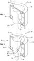
- Fig. 3 shows a measurement means 20 according to a second embodiment of the invention wherein similar elements as in the first embodiment are characterized equivalently.
- the measurement means 20 is configured as a capacitive sensor 30 comprising a first cylinder 32 and a second cylinder 34 wherein a first surface of the first cylinder 32 provides a first capacitor plate 36 and a second surface of the second cylinder 34 provides a second capacitor plate 38 separated to each other by a distance d. If the guide pillar 10, in which the capacitive sensor 30 is embedded in any appropriate way in the longitudinal bore 14, is subjected to deformation or deflection the first and/or second capacitor plates 36, 38 will experience translation and/or rotation, which will affect the distance d and thus directly the determined capacitance of the capacitor sensor 30.
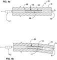
- Figures 4a and 4b shows a measurement means 20 according to a third embodiment of the invention.
- the figures 4a and 4b show schematically a guide pillar 10 in which a fiber optic sensor 40 is embedded in the longitudinal bore 14 coaxially with the guide pillar axis 16.
- the optical sensor 40 is configured as a fiber optic sensor, in particular as an interferometric sensor comprising a process unit 42 comprising inter alia an interferometer such as a Fabry-Perot-Interferometer, a transducer to convert an optical signal into an electrical signal and a processor.
- an interferometer such as a Fabry-Perot-Interferometer
- a transducer to convert an optical signal into an electrical signal
- a processor for example light from a low-coherence source (not shown) is divided into a measurement fiber 44 and a reference fiber 46 arranged inside of the measuring means 20.
- the measurement fiber 44 is connected to the measuring means 20 such that during bending the measurement fiber 44 is elongated.
- Fig. 4a shows the guide pillar 10 in a straight position.
- Fig. 4b shows the guide pillar 10 subjected to deflection that can be detected by the fiber optic sensor 40.
Landscapes
- Engineering & Computer Science (AREA)
- Mechanical Engineering (AREA)
- Physics & Mathematics (AREA)
- General Physics & Mathematics (AREA)
- Optics & Photonics (AREA)
- Manufacturing & Machinery (AREA)
- Length Measuring Devices By Optical Means (AREA)
- Measurement Of Length, Angles, Or The Like Using Electric Or Magnetic Means (AREA)
- Presses And Accessory Devices Thereof (AREA)
- Control Of Presses (AREA)
Applications Claiming Priority (1)
| Application Number | Priority Date | Filing Date | Title |
|---|---|---|---|
| CH12572019 | 2019-10-03 |
Publications (3)
| Publication Number | Publication Date |
|---|---|
| EP3799970A1 EP3799970A1 (en) | 2021-04-07 |
| EP3799970B1 true EP3799970B1 (en) | 2024-05-01 |
| EP3799970C0 EP3799970C0 (en) | 2024-05-01 |
Family
ID=69190584
Family Applications (1)
| Application Number | Title | Priority Date | Filing Date |
|---|---|---|---|
| EP20198867.2A Active EP3799970B1 (en) | 2019-10-03 | 2020-09-29 | System for monitoring standard parts |
Country Status (5)
| Country | Link |
|---|---|
| US (1) | US11628532B2 (enExample) |
| EP (1) | EP3799970B1 (enExample) |
| JP (1) | JP7399050B2 (enExample) |
| CN (1) | CN112611314B (enExample) |
| PL (1) | PL3799970T3 (enExample) |
Families Citing this family (3)
| Publication number | Priority date | Publication date | Assignee | Title |
|---|---|---|---|---|
| NL2024038B1 (en) * | 2019-10-17 | 2021-06-22 | Boschman Tech B V | Component Processing Apparatus, such as a Pressure Sintering Apparatus or a Component Encapsulation Apparatus |
| WO2024197372A1 (pt) * | 2023-03-27 | 2024-10-03 | Fras-Le S.A. | Sistema e processo de monitoramento de desalinhamento entre colunas de prensa |
| CN119550581B (zh) * | 2024-12-11 | 2025-10-10 | 中山市精研科技有限公司 | 一种led屏幕用外壳注塑成型装置及工艺 |
Family Cites Families (18)
| Publication number | Priority date | Publication date | Assignee | Title |
|---|---|---|---|---|
| US3425260A (en) * | 1966-08-18 | 1969-02-04 | Atlas Chain Co Ltd | Double action press tool |
| GB1508213A (en) * | 1975-04-08 | 1978-04-19 | British Steel Corp | Rolling mill equipment |
| SU572318A1 (ru) * | 1976-03-22 | 1977-09-15 | Паневежский Завод Точной Механики | Уел направлени штампа |
| US4491027A (en) * | 1983-01-31 | 1985-01-01 | Tetrahedron Associates, Inc. | Wide-range load cell |
| DE4415577B4 (de) * | 1994-05-03 | 2007-02-22 | Müller Weingarten AG | Einrichtung zur Kompensation bzw. gezielten Einstellung von Durchbiegungen in Pressen der Umformtechnik |
| JP3645762B2 (ja) * | 1999-10-18 | 2005-05-11 | トヨタ自動車株式会社 | プレス機械の診断方法及びその装置 |
| DE10116917A1 (de) | 2001-04-05 | 2002-10-10 | Kramski Gmbh | Führungsvorrichtung für Werkzeugmaschinen |
| CN101370603B (zh) * | 2006-01-13 | 2011-12-28 | 新日本制铁株式会社 | 冲压成形装置及冲压成形方法 |
| CN101544042A (zh) * | 2008-03-26 | 2009-09-30 | 鸿富锦精密工业(深圳)有限公司 | 检测装置 |
| BRPI0822792B1 (pt) * | 2008-09-23 | 2019-04-16 | Voith Patent Gmbh | Rolo industrial com sistema sensor de cobertura do rolo ótico |
| CN102176988B (zh) * | 2008-10-07 | 2013-05-15 | 新日铁住金株式会社 | 金属冲压成形品的裂缝判定方法、装置、程序以及记录介质 |
| JP2013052428A (ja) | 2011-09-05 | 2013-03-21 | Toyota Motor Corp | プレス装置 |
| WO2015178267A1 (ja) * | 2014-05-19 | 2015-11-26 | 新日鐵住金株式会社 | プレス成形方法及びプレス成形用金型 |
| JP6002205B2 (ja) * | 2014-12-26 | 2016-10-05 | アイダエンジニアリング株式会社 | クッションパッドの傾き確認装置及び方法 |
| DE102015106933A1 (de) * | 2015-05-04 | 2016-11-10 | Technische Universität Darmstadt | Maschinenelement mit einer Sensoreinrichtung und Verfahren zur Herstellung eines Maschinenelements |
| US10549330B2 (en) * | 2016-10-06 | 2020-02-04 | GM Global Technology Operations LLC | Live pilot sensing apparatus |
| JP6259897B1 (ja) | 2016-12-02 | 2018-01-10 | 三菱長崎機工株式会社 | ネジ無しタイロッドを備えたプレス装置 |
| CN108787889B (zh) * | 2018-06-22 | 2019-07-19 | 广州紫江包装有限公司 | 一种模具精准定位装置 |
-
2020
- 2020-08-27 JP JP2020143450A patent/JP7399050B2/ja active Active
- 2020-08-28 US US17/005,430 patent/US11628532B2/en active Active
- 2020-09-29 PL PL20198867.2T patent/PL3799970T3/pl unknown
- 2020-09-29 EP EP20198867.2A patent/EP3799970B1/en active Active
- 2020-10-09 CN CN202011071898.3A patent/CN112611314B/zh active Active
Also Published As
| Publication number | Publication date |
|---|---|
| EP3799970A1 (en) | 2021-04-07 |
| CN112611314B (zh) | 2025-07-01 |
| US20210101243A1 (en) | 2021-04-08 |
| JP2021058932A (ja) | 2021-04-15 |
| JP7399050B2 (ja) | 2023-12-15 |
| PL3799970T3 (pl) | 2024-07-08 |
| US11628532B2 (en) | 2023-04-18 |
| EP3799970C0 (en) | 2024-05-01 |
| CN112611314A (zh) | 2021-04-06 |
Similar Documents
| Publication | Publication Date | Title |
|---|---|---|
| EP3799970B1 (en) | System for monitoring standard parts | |
| US4177568A (en) | Measurement head | |
| US7296364B2 (en) | Sensor module for a probe head of a tactile coordinated measuring machine | |
| EP3076124B1 (en) | Tactile probing system | |
| EP1451538B1 (en) | Sealed load cell | |
| EP0156081B1 (en) | Pressure transducer | |
| US10036766B2 (en) | Method for producing a force-measuring element | |
| CN116940818A (zh) | 用于对多个轴中的变形、应力、力和/或扭矩进行测量的装置 | |
| JP3517185B2 (ja) | スケール部材、その製造方法及びそれを用いた変位計 | |
| JP2021058932A5 (enExample) | ||
| US5211060A (en) | Bidirectional force sensor | |
| CN105627949B (zh) | 光学传感式三维高精度接触扫描测量探头 | |
| US7187107B2 (en) | Closed-loop feedback control positioning stage | |
| US4213319A (en) | Thickness gauge | |
| EP3563131B1 (en) | MEASURING ELEMENT, MEASURING SYSTEM AND METHOD FOR SUPPLYING A MEASURING ELEMENT FOR THE MEASUREMENT OF FORCES | |
| US3779647A (en) | Interferometric device for indicating displacement along one dimension during motion along another dimension | |
| CN114473263A (zh) | 蒙皮与加强框的激光焊接工装及使用其的激光焊接方法 | |
| JP2004347354A (ja) | プレス成形中の金型変位量の測定方法および測定装置 | |
| KR101244264B1 (ko) | 형상 측정기 | |
| US4884346A (en) | Apparatus for linear measurements | |
| JP3487467B2 (ja) | ガラスレンズの製造方法 | |
| JP7254997B2 (ja) | 測定ヘッド及びその温度特性を調整する方法 | |
| RU2848789C1 (ru) | Устройство для перемещения исполнительного органа | |
| JP7640617B2 (ja) | 外径測定器 | |
| CN223106945U (zh) | 一种新微应变传感器标定装置 |
Legal Events
| Date | Code | Title | Description |
|---|---|---|---|
| PUAI | Public reference made under article 153(3) epc to a published international application that has entered the european phase |
Free format text: ORIGINAL CODE: 0009012 |
|
| STAA | Information on the status of an ep patent application or granted ep patent |
Free format text: STATUS: THE APPLICATION HAS BEEN PUBLISHED |
|
| AK | Designated contracting states |
Kind code of ref document: A1 Designated state(s): AL AT BE BG CH CY CZ DE DK EE ES FI FR GB GR HR HU IE IS IT LI LT LU LV MC MK MT NL NO PL PT RO RS SE SI SK SM TR |
|
| AX | Request for extension of the european patent |
Extension state: BA ME |
|
| STAA | Information on the status of an ep patent application or granted ep patent |
Free format text: STATUS: REQUEST FOR EXAMINATION WAS MADE |
|
| 17P | Request for examination filed |
Effective date: 20210915 |
|
| RBV | Designated contracting states (corrected) |
Designated state(s): AL AT BE BG CH CY CZ DE DK EE ES FI FR GB GR HR HU IE IS IT LI LT LU LV MC MK MT NL NO PL PT RO RS SE SI SK SM TR |
|
| STAA | Information on the status of an ep patent application or granted ep patent |
Free format text: STATUS: EXAMINATION IS IN PROGRESS |
|
| 17Q | First examination report despatched |
Effective date: 20220413 |
|
| REG | Reference to a national code |
Ref country code: DE Ref legal event code: R079 Free format text: PREVIOUS MAIN CLASS: B21D0022200000 Ipc: B21D0037120000 Ref country code: DE Ref legal event code: R079 Ref document number: 602020029986 Country of ref document: DE Free format text: PREVIOUS MAIN CLASS: B21D0022200000 Ipc: B21D0037120000 |
|
| GRAP | Despatch of communication of intention to grant a patent |
Free format text: ORIGINAL CODE: EPIDOSNIGR1 |
|
| STAA | Information on the status of an ep patent application or granted ep patent |
Free format text: STATUS: GRANT OF PATENT IS INTENDED |
|
| RIC1 | Information provided on ipc code assigned before grant |
Ipc: B30B 15/04 20060101ALI20230207BHEP Ipc: B30B 15/00 20060101ALI20230207BHEP Ipc: B21D 37/12 20060101AFI20230207BHEP |
|
| INTG | Intention to grant announced |
Effective date: 20230227 |
|
| GRAJ | Information related to disapproval of communication of intention to grant by the applicant or resumption of examination proceedings by the epo deleted |
Free format text: ORIGINAL CODE: EPIDOSDIGR1 |
|
| STAA | Information on the status of an ep patent application or granted ep patent |
Free format text: STATUS: EXAMINATION IS IN PROGRESS |
|
| INTC | Intention to grant announced (deleted) | ||
| GRAP | Despatch of communication of intention to grant a patent |
Free format text: ORIGINAL CODE: EPIDOSNIGR1 |
|
| STAA | Information on the status of an ep patent application or granted ep patent |
Free format text: STATUS: GRANT OF PATENT IS INTENDED |
|
| INTG | Intention to grant announced |
Effective date: 20230707 |
|
| GRAJ | Information related to disapproval of communication of intention to grant by the applicant or resumption of examination proceedings by the epo deleted |
Free format text: ORIGINAL CODE: EPIDOSDIGR1 |
|
| STAA | Information on the status of an ep patent application or granted ep patent |
Free format text: STATUS: EXAMINATION IS IN PROGRESS |
|
| GRAP | Despatch of communication of intention to grant a patent |
Free format text: ORIGINAL CODE: EPIDOSNIGR1 |
|
| STAA | Information on the status of an ep patent application or granted ep patent |
Free format text: STATUS: GRANT OF PATENT IS INTENDED |
|
| INTC | Intention to grant announced (deleted) | ||
| INTG | Intention to grant announced |
Effective date: 20231123 |
|
| GRAS | Grant fee paid |
Free format text: ORIGINAL CODE: EPIDOSNIGR3 |
|
| GRAA | (expected) grant |
Free format text: ORIGINAL CODE: 0009210 |
|
| STAA | Information on the status of an ep patent application or granted ep patent |
Free format text: STATUS: THE PATENT HAS BEEN GRANTED |
|
| AK | Designated contracting states |
Kind code of ref document: B1 Designated state(s): AL AT BE BG CH CY CZ DE DK EE ES FI FR GB GR HR HU IE IS IT LI LT LU LV MC MK MT NL NO PL PT RO RS SE SI SK SM TR |
|
| REG | Reference to a national code |
Ref country code: GB Ref legal event code: FG4D |
|
| REG | Reference to a national code |
Ref country code: CH Ref legal event code: EP |
|
| REG | Reference to a national code |
Ref country code: IE Ref legal event code: FG4D |
|
| REG | Reference to a national code |
Ref country code: DE Ref legal event code: R096 Ref document number: 602020029986 Country of ref document: DE |
|
| U01 | Request for unitary effect filed |
Effective date: 20240517 |
|
| U07 | Unitary effect registered |
Designated state(s): AT BE BG DE DK EE FI FR IT LT LU LV MT NL PT SE SI Effective date: 20240529 |
|
| PG25 | Lapsed in a contracting state [announced via postgrant information from national office to epo] |
Ref country code: IS Free format text: LAPSE BECAUSE OF FAILURE TO SUBMIT A TRANSLATION OF THE DESCRIPTION OR TO PAY THE FEE WITHIN THE PRESCRIBED TIME-LIMIT Effective date: 20240901 |
|
| U20 | Renewal fee for the european patent with unitary effect paid |
Year of fee payment: 5 Effective date: 20240830 |
|
| PG25 | Lapsed in a contracting state [announced via postgrant information from national office to epo] |
Ref country code: HR Free format text: LAPSE BECAUSE OF FAILURE TO SUBMIT A TRANSLATION OF THE DESCRIPTION OR TO PAY THE FEE WITHIN THE PRESCRIBED TIME-LIMIT Effective date: 20240501 |
|
| PG25 | Lapsed in a contracting state [announced via postgrant information from national office to epo] |
Ref country code: GR Free format text: LAPSE BECAUSE OF FAILURE TO SUBMIT A TRANSLATION OF THE DESCRIPTION OR TO PAY THE FEE WITHIN THE PRESCRIBED TIME-LIMIT Effective date: 20240802 |
|
| PG25 | Lapsed in a contracting state [announced via postgrant information from national office to epo] |
Ref country code: ES Free format text: LAPSE BECAUSE OF FAILURE TO SUBMIT A TRANSLATION OF THE DESCRIPTION OR TO PAY THE FEE WITHIN THE PRESCRIBED TIME-LIMIT Effective date: 20240501 |
|
| PG25 | Lapsed in a contracting state [announced via postgrant information from national office to epo] |
Ref country code: GR Free format text: LAPSE BECAUSE OF FAILURE TO SUBMIT A TRANSLATION OF THE DESCRIPTION OR TO PAY THE FEE WITHIN THE PRESCRIBED TIME-LIMIT Effective date: 20240802 Ref country code: ES Free format text: LAPSE BECAUSE OF FAILURE TO SUBMIT A TRANSLATION OF THE DESCRIPTION OR TO PAY THE FEE WITHIN THE PRESCRIBED TIME-LIMIT Effective date: 20240501 Ref country code: NO Free format text: LAPSE BECAUSE OF FAILURE TO SUBMIT A TRANSLATION OF THE DESCRIPTION OR TO PAY THE FEE WITHIN THE PRESCRIBED TIME-LIMIT Effective date: 20240801 Ref country code: IS Free format text: LAPSE BECAUSE OF FAILURE TO SUBMIT A TRANSLATION OF THE DESCRIPTION OR TO PAY THE FEE WITHIN THE PRESCRIBED TIME-LIMIT Effective date: 20240901 Ref country code: HR Free format text: LAPSE BECAUSE OF FAILURE TO SUBMIT A TRANSLATION OF THE DESCRIPTION OR TO PAY THE FEE WITHIN THE PRESCRIBED TIME-LIMIT Effective date: 20240501 Ref country code: RS Free format text: LAPSE BECAUSE OF FAILURE TO SUBMIT A TRANSLATION OF THE DESCRIPTION OR TO PAY THE FEE WITHIN THE PRESCRIBED TIME-LIMIT Effective date: 20240801 |
|
| PG25 | Lapsed in a contracting state [announced via postgrant information from national office to epo] |
Ref country code: RO Free format text: LAPSE BECAUSE OF FAILURE TO SUBMIT A TRANSLATION OF THE DESCRIPTION OR TO PAY THE FEE WITHIN THE PRESCRIBED TIME-LIMIT Effective date: 20240501 Ref country code: SK Free format text: LAPSE BECAUSE OF FAILURE TO SUBMIT A TRANSLATION OF THE DESCRIPTION OR TO PAY THE FEE WITHIN THE PRESCRIBED TIME-LIMIT Effective date: 20240501 |
|
| PG25 | Lapsed in a contracting state [announced via postgrant information from national office to epo] |
Ref country code: SM Free format text: LAPSE BECAUSE OF FAILURE TO SUBMIT A TRANSLATION OF THE DESCRIPTION OR TO PAY THE FEE WITHIN THE PRESCRIBED TIME-LIMIT Effective date: 20240501 |
|
| PG25 | Lapsed in a contracting state [announced via postgrant information from national office to epo] |
Ref country code: SM Free format text: LAPSE BECAUSE OF FAILURE TO SUBMIT A TRANSLATION OF THE DESCRIPTION OR TO PAY THE FEE WITHIN THE PRESCRIBED TIME-LIMIT Effective date: 20240501 Ref country code: SK Free format text: LAPSE BECAUSE OF FAILURE TO SUBMIT A TRANSLATION OF THE DESCRIPTION OR TO PAY THE FEE WITHIN THE PRESCRIBED TIME-LIMIT Effective date: 20240501 Ref country code: RO Free format text: LAPSE BECAUSE OF FAILURE TO SUBMIT A TRANSLATION OF THE DESCRIPTION OR TO PAY THE FEE WITHIN THE PRESCRIBED TIME-LIMIT Effective date: 20240501 |
|
| PGFP | Annual fee paid to national office [announced via postgrant information from national office to epo] |
Ref country code: CH Payment date: 20241001 Year of fee payment: 5 |
|
| REG | Reference to a national code |
Ref country code: DE Ref legal event code: R097 Ref document number: 602020029986 Country of ref document: DE |
|
| PLBE | No opposition filed within time limit |
Free format text: ORIGINAL CODE: 0009261 |
|
| STAA | Information on the status of an ep patent application or granted ep patent |
Free format text: STATUS: NO OPPOSITION FILED WITHIN TIME LIMIT |
|
| 26N | No opposition filed |
Effective date: 20250204 |
|
| PG25 | Lapsed in a contracting state [announced via postgrant information from national office to epo] |
Ref country code: MC Free format text: LAPSE BECAUSE OF FAILURE TO SUBMIT A TRANSLATION OF THE DESCRIPTION OR TO PAY THE FEE WITHIN THE PRESCRIBED TIME-LIMIT Effective date: 20240501 |
|
| GBPC | Gb: european patent ceased through non-payment of renewal fee |
Effective date: 20240929 |
|
| PG25 | Lapsed in a contracting state [announced via postgrant information from national office to epo] |
Ref country code: GB Free format text: LAPSE BECAUSE OF NON-PAYMENT OF DUE FEES Effective date: 20240929 |
|
| REG | Reference to a national code |
Ref country code: CH Ref legal event code: U11 Free format text: ST27 STATUS EVENT CODE: U-0-0-U10-U11 (AS PROVIDED BY THE NATIONAL OFFICE) Effective date: 20251001 |
|
| U20 | Renewal fee for the european patent with unitary effect paid |
Year of fee payment: 6 Effective date: 20250826 |
|
| PGFP | Annual fee paid to national office [announced via postgrant information from national office to epo] |
Ref country code: PL Payment date: 20250919 Year of fee payment: 6 Ref country code: TR Payment date: 20250923 Year of fee payment: 6 |
|
| PGFP | Annual fee paid to national office [announced via postgrant information from national office to epo] |
Ref country code: IE Payment date: 20250918 Year of fee payment: 6 Ref country code: CZ Payment date: 20250925 Year of fee payment: 6 |