EP3799491B1 - Benutzerendgerät und drahtloskommunikationsverfahren - Google Patents
Benutzerendgerät und drahtloskommunikationsverfahren Download PDFInfo
- Publication number
- EP3799491B1 EP3799491B1 EP18919656.1A EP18919656A EP3799491B1 EP 3799491 B1 EP3799491 B1 EP 3799491B1 EP 18919656 A EP18919656 A EP 18919656A EP 3799491 B1 EP3799491 B1 EP 3799491B1
- Authority
- EP
- European Patent Office
- Prior art keywords
- bwp
- ssb
- information
- section
- base station
- Prior art date
- Legal status (The legal status is an assumption and is not a legal conclusion. Google has not performed a legal analysis and makes no representation as to the accuracy of the status listed.)
- Active
Links
Images


Classifications
-
- H—ELECTRICITY
- H04—ELECTRIC COMMUNICATION TECHNIQUE
- H04L—TRANSMISSION OF DIGITAL INFORMATION, e.g. TELEGRAPHIC COMMUNICATION
- H04L5/00—Arrangements affording multiple use of the transmission path
- H04L5/003—Arrangements for allocating sub-channels of the transmission path
- H04L5/0048—Allocation of pilot signals, i.e. of signals known to the receiver
-
- H—ELECTRICITY
- H04—ELECTRIC COMMUNICATION TECHNIQUE
- H04W—WIRELESS COMMUNICATION NETWORKS
- H04W56/00—Synchronisation arrangements
- H04W56/001—Synchronization between nodes
-
- H—ELECTRICITY
- H04—ELECTRIC COMMUNICATION TECHNIQUE
- H04L—TRANSMISSION OF DIGITAL INFORMATION, e.g. TELEGRAPHIC COMMUNICATION
- H04L5/00—Arrangements affording multiple use of the transmission path
- H04L5/0001—Arrangements for dividing the transmission path
- H04L5/0003—Two-dimensional division
- H04L5/0005—Time-frequency
- H04L5/0007—Time-frequency the frequencies being orthogonal, e.g. OFDM(A) or DMT
- H04L5/001—Time-frequency the frequencies being orthogonal, e.g. OFDM(A) or DMT the frequencies being arranged in component carriers
-
- H—ELECTRICITY
- H04—ELECTRIC COMMUNICATION TECHNIQUE
- H04L—TRANSMISSION OF DIGITAL INFORMATION, e.g. TELEGRAPHIC COMMUNICATION
- H04L5/00—Arrangements affording multiple use of the transmission path
- H04L5/003—Arrangements for allocating sub-channels of the transmission path
- H04L5/0048—Allocation of pilot signals, i.e. of signals known to the receiver
- H04L5/0051—Allocation of pilot signals, i.e. of signals known to the receiver of dedicated pilots, i.e. pilots destined for a single user or terminal
-
- H—ELECTRICITY
- H04—ELECTRIC COMMUNICATION TECHNIQUE
- H04L—TRANSMISSION OF DIGITAL INFORMATION, e.g. TELEGRAPHIC COMMUNICATION
- H04L5/00—Arrangements affording multiple use of the transmission path
- H04L5/003—Arrangements for allocating sub-channels of the transmission path
- H04L5/0053—Allocation of signalling, i.e. of overhead other than pilot signals
-
- H—ELECTRICITY
- H04—ELECTRIC COMMUNICATION TECHNIQUE
- H04W—WIRELESS COMMUNICATION NETWORKS
- H04W72/00—Local resource management
- H04W72/04—Wireless resource allocation
- H04W72/044—Wireless resource allocation based on the type of the allocated resource
- H04W72/0453—Resources in frequency domain, e.g. a carrier in FDMA
-
- H—ELECTRICITY
- H04—ELECTRIC COMMUNICATION TECHNIQUE
- H04W—WIRELESS COMMUNICATION NETWORKS
- H04W72/00—Local resource management
- H04W72/20—Control channels or signalling for resource management
- H04W72/23—Control channels or signalling for resource management in the downlink direction of a wireless link, i.e. towards a terminal
Definitions
- the present disclosure relates to a user terminal and a radio communication method in next-generation mobile communication systems.
- LTE long-term evolution
- LTE-A LTE Advanced, LTE Rel.10, 11, 12, and 13
- LTE Rel.8, 9 LTE Rel.8, 9
- a user terminal In the existing LTE system (for example, LTE Rel.8 to 13), a user terminal (UE (User Equipment)) detects a synchronization signal (SS) to be synchronized with a network (for example, a base station (eNB (eNode B))), and identifies a cell to be connected (for example, identifies by a cell ID (Identifier)). Such processing is also referred to as cell search.
- the synchronization signal includes, for example, PSS (Primary Synchronization Signal) and/or SSS (Secondary Synchronization Signal)).
- the UE receives broadcast information (for example, a master information block (MIB), a system information block (SIB), etc.), and acquires configuration information for communication with the network (which may also be referred to as "system information” and so on).
- broadcast information for example, a master information block (MIB), a system information block (SIB), etc.
- SIB system information block
- configuration information for communication with the network which may also be referred to as "system information” and so on.
- SSB synchronization signal block
- partial frequency bands also referred to as “partial bands,” “bandwidth parts (BWPs)” and so on
- carriers also referred to as component carriers (CCs), system bands and so on
- BWPs bandwidth parts
- CCs component carriers
- DL/UL communication DL/UL communication
- the SSB is not necessarily included in each BWP, and hence when activation/deactivation of BWPs is controlled by switching, which signal (for example, SSB or any of other reference signals) is to be used for a specific operation in each BWP becomes a problem. If various operations using the SSB cannot be properly implemented, communication quality may deteriorate.
- communication can be appropriately controlled using at least one of the synchronization signal block and the reference signal.
- NR is expected to have both a user terminal (also referred to as a WB (Wideband) UE, single carrier WB UE and so on) having a capability of performing transmission and/or reception (transmission/reception) over the entire carrier and a user terminal (also referred to as a BW (Bandwidth) reduced UE and so on) with no capability of performing transmission/reception over the entire carrier.
- a user terminal also referred to as a WB (Wideband) UE, single carrier WB UE and so on
- BW Bandwidth
- the future radio communication systems are expected to have a plurality of user terminals (various BW UE capabilities) in a supported bandwidth.
- quasi-static configuring of one or more partial frequency bands in a carrier has been under study.
- Each frequency band (for example, 50 MHz or 200 MHz) in the carrier is referred to as a "partial band,” a “bandwidth part (BWP)" and so on.
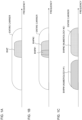
- Fig. 1 is a diagram illustrating an example of a BWP configuration scenario.
- Fig. 1A illustrates a scenario (Usage scenario #1) in which one BWP is configured for a user terminal in one carrier.
- a BWP of 200 MHz is configured in a carrier of 800 MHz.
- Activation or deactivation of the BWP may be controlled.
- Fig. 1B illustrates a scenario (Usage scenario #2) in which a plurality of BWPs are configured for a user terminal in one carrier. As illustrated in Fig. 1B , at least a part of the plurality of BWPs (for example, BWPs #1 and #2) may overlap with each other. For example, in Fig. 1B , the BWP #1 is a partial frequency band of the BWP #2.
- Fig. 1C illustrates a scenario (Usage scenario #3) in which a plurality of BWPs are configured in different bands within one carrier.
- the plurality of BWPs may employ different numerologies.
- the numerologies may be at least one of subcarrier interval, symbol length, slot length, cyclic prefix (CP) length, slot (transmission time interval (TTI)) length, the number of symbols per slot and so on.
- the BWP used for DL communication may be referred to as a "DL BWP (frequency band for DL)," and the BWP used for UL communication may be referred to as an "UL BWP (frequency band for UL).”
- the frequency bands of the DL BWP and the UL BWP may at least partially overlap with each other.
- the DL BWP and the UL BWP are referred to as BWP, when they are not distinguished from each other.
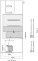
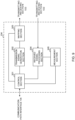
- FIG. 2 is a diagram illustrating a control example in a case of activating one BWP (switching activated BWPs).
- the scenario illustrated in Fig. 1B is assumed, but the activation/deactivation control of the BWP can be applied as appropriate to the scenarios illustrated in Figs. 1A and 1C or the like.
- a control resource region (CORESET #1) that is an allocation candidate of a DL control channel (DCI) is configured in the BWP #1
- CORESET #2 is configured in the BWP #2.
- Each of the CORESET #1 and the CORESET #2 is provided with one or more search spaces.
- the DCI for the BWP #1, and the DCI for the BWP #2 may be arranged in the same search space, or may be arranged in different search spaces.
- the user terminal monitors the search space in the CORESET #1 within a given cycle (for example, for each one or more slots, for each one or more minislots, or for each given number of symbols) (blind decoding), to detect the DCI for the user terminal.
- the DCI may include information indicating the BWP corresponding to the DCI (BWP information).
- BWP information is, for example, a BWP index, and may be a given field value in the DCI.
- the BWP index information may be included in a downlink scheduling DCI, may be included in an uplink scheduling DCI, or may be included in a common search space DCI.
- the user terminal may determine the BWP for which PDSCH or PUSCH is scheduled by the DCI, based on the BWP information in the DCI.
- the user terminal When the user terminal detects the DCI for the BWP #1 in the CORESET #1, the user terminal receives PDSCH scheduled in (assigned to) a given time and/or frequency resource (time/frequency resource) in the BWP #1 based on the DCI for the BWP #1.
- the user terminal When the DCI for the BWP #2 is detected in the CORESET #1, the user terminal deactivates the BWP #1 and activates the BWP #2. The user terminal receives the PDSCH scheduled in a given time/frequency resource of the DL BWP #2 based on the DCI for the BWP #2 detected in the CORESET #1.
- the user terminal When the BWP #2 is activated, the user terminal monitors the search space in the CORESET #2 within a given cycle (for example, for each one or more slots, for each one or more minislots, or for each given number of symbols) (blind decoding), to detect the DCI for the BWP #2.
- the user terminal may receive the PDSCH scheduled in a given time/frequency resource of the BWP #2 based on the DCI for the BWP #2 detected in the CORESET #2.
- the BWP may be deactivated.
- the user terminal deactivates the BWP #2 and activates the BWP #1 because PDSCH is not scheduled in the DL BWP #2 for a given period of time.
- the maximum number of BWPs that can be configured per carrier may be given. For example, in frequency division duplex (FDD) (paired spectrum), a maximum of four DL BWPs and a maximum of four UL BWPs may be configured per carrier.
- FDD frequency division duplex
- a default BWP may be defined in the user terminal.
- the default BWP may be the above-mentioned initial active BWP, or may be configured by higher layer signaling (for example, RRC signaling).
- the UE tunes the reception frequency and bandwidth according to the frequency position and bandwidth of the activated BWP (for example, DL BWP).
- the user terminal that supports the entire carrier will be able to receive and/or transmit signals outside the activated BWP to some extent.
- the reception frequency and the bandwidth are configured according to the activated BWP, reception of signals or channels transmitted outside the band of the BWP is limited.
- the UE performs measurement using a synchronization signal block (SSB) transmitted in a frequency domain outside the range of the active DL BWP (for example, RRM measurement (Radio Resource Management Measurement)).
- SSB synchronization signal block
- RRM measurement Radio Resource Management Measurement
- the SSB is a signal block including a synchronization signal (SS) and a broadcast channel (which may also be referred to as a "broadcast signal,” “PBCH,” “NR-PBCH” and so on), and may be referred to as “SS/PBCH block” and so on.
- SS synchronization signal
- PBCH broadcast channel
- NR-PBCH NR-PBCH
- the SS included in the SSB may include a primary synchronization signal (PSS), a secondary synchronization signal (SSS) and so on.
- the SSB is composed of one or more symbols (for example, OFDM symbols).
- the PSS, the SSS, and the PBCH may be arranged in one or more different symbols.
- the SSB may be composed of a total of four or five symbols including one symbol PSS, one symbol SSS, and two or three symbol PBCH.
- radio link monitoring using the SSB, beam management, beam failure detection, and so on can be performed only when the SSB is included in the BWP. That is, the UE cannot perform these operations using the SSB in the DL BWP not including the SSB.
- the SSB is considered to be transmitted at a plurality of frequency positions within a carrier.
- the SSB and given system information are transmitted on at least one frequency.
- the SSB is transmitted by a sync raster searched by the UE at the time of initial access.
- the given system information (RMSI) may not be transmitted, and the base station uses a higher layer (for example, RRC signaling) to report one frequency position of the SSB to the UE.
- RRC signaling for example, RRC signaling
- the beam recovery may include at least one of beam failure detection and candidate beam detection.
- the beam management may be measurement for L1-RSRP (Reference Signal Received Power (RSRP) at the physical layer).
- RSRP Reference Signal Received Power
- the TCI state corresponds to a pseudo collocation (QCL (Quasi-Co-Location)) state. Further, the TCI state is roughly classified into a TCI state for PDCCH and a TCI state for PDSCH.
- the TCI state may be, for example, information regarding a QCL of a target channel (or a reference signal for the channel (RS (Reference Signal))) and another signal (for example, another downlink reference signal (DL-RS (Downlink Reference Signal))).
- RS Reference Signal
- DL-RS Downlink Reference Signal
- the TCI state may be information regarding a spatial QCL (which may also be referred to as "QCL type-D") of DMRS for PDCCH or PDSCH and another DL signal (for example, SSB or CSI-RS), and may be used to determine a reception beam pattern when PDCCH or PDSCH is received.
- QCL spatial QCL
- SSB SSB
- CSI-RS CSI-RS
- the base station is supported to report one frequency to the UE by using a higher layer (for example, RRC signaling).
- the base station uses a given information element (frequencyInfoDL in ServingCellConfigCommon) to specify the frequency of one SSB to the UE.
- a plurality of BWPs are configured for the UE, and there is a BWP that includes a frequency domain in which the SSB is transmitted and a BWP not including the frequency domain in the plurality of configured BWPs.
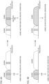
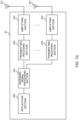
- how to control various operations in the case of performing switching between the BWP including the SSB and the BWP not including the SSB becomes a problem (see Fig. 3A).
- Fig. 3A illustrates a case where the active state is switched from a BWP #0 including the SSB to the BWP #1 not including the SSB.
- the SSB can be transmitted in each band of the plurality of configured BWPs.
- the UE may not be able to grasp the frequency position of the SSB when the BWP not including the SSB is activated from the BWP including the SSB (see Fig. 3B).
- Fig. 3B illustrates a case where the active state is switched from the BWP #0 including the SSB of which frequency position is reported by a given information element to the BWP #1 not including the SSB (including another SSB not reported by the given information element).
- the present inventors have focused on the presence or absence of the SSB in the BWP to be configured or the BWP to be activated, or the type of SSB (for example, whether or not it is the SSB reported by the given information element), and have conceived to decide whether to apply the synchronization signal block to various operations based on the information reported from the base station.
- the SSB frequency position may be reported to the UE in association with the BWP for a specific operation.
- the SSB may be applied to another operation.
- the UE may refer to the information regarding the frequency position of the SSB reported for a specific operation in a given BWP for another operation.
- various operations using the SSB are limited to the case where the BWP including the SSB frequency position reported by the given information element (for example, ServingCellConfigCommon) reported by the serving cell to be shared by the base station is in the active state.
- the given information element for example, ServingCellConfigCommon
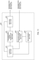
- the UE controls whether or not to apply the SSB to various operations based on the type of the activated BWP (for example, whether or not the SSB of which frequency position is reported is included) (see Fig. 5).
- Fig. 5 illustrates a case where the active state is switched from the BWP #0 including the SSB of which frequency position is reported by the given information element (ServingCellConfigCommon) to the BWP #1 not including the SSB.
- the UE when the BWP #0 is in the active state, the UE performs various operations using at least the SSB of which frequency position is reported by the given information element in the BWP #0.
- the UE when the BWP in the active state is switched from the BWP #0 to the BWP #1, the UE may perform various operations using another DL signal (for example, CSI-RS) included in the BWP #1.
- another DL signal for example, CSI-RS
- the reference signal applied to various operations can be appropriately determined.
- various operations using the SSB are limited to the case where only the BWP including the SSB frequency position reported by the given information element (for example, ServingCellConfigCommon) from the base station is configured.
- the given information element for example, ServingCellConfigCommon
- the UE When various operations using the SSB are configured, the UE performs various operations without switching the frequency position of the SSB, assuming that the frequency of the SSB is included in the BWP band regardless the switched BWP.
- the third aspect may control the application/non-application for each UE.
- at least some UEs (for example, UE of Rel.15) may assume that the BWP not including the SSB is not configured when various operations using the SSB are configured.
- Applicability of the first aspect or the second aspect may be defined as UE capability information (UE capability).
- UE capability UE capability information
- a UE that supports the operation shown in the first aspect reports that effect to the network (for example, a base station) as UE capability information.
- a UE that does not support the operation shown in the first aspect reports that effect to the base station as UE capability information.
- the base station may control the presence or absence of configuration of various operations using the SSB in a given BWP for each UE based on the capability information reported from the UE.
- radio communication system communication is performed using one or a combination of the radio communication methods according to each of the above embodiments of the present disclosure.
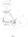
- Fig. 7 is a diagram illustrating an example of a schematic configuration of a radio communication system according to one embodiment.
- a radio communication system 1 can adopt carrier aggregation (CA) and/or dual connectivity (DC) to group a plurality of fundamental frequency blocks (component carriers) into one, where the LTE system bandwidth (for example, 20 MHz) constitutes one unit.
- CA carrier aggregation
- DC dual connectivity
- the radio communication system 1 may also be referred to as “LTE (Long Term Evolution),” “LTE-A (LTE-Advanced),” “LTE-B (LTE-Beyond),” "SUPER 3G,” “IMT-Advanced,” “4G (4th generation mobile communication system),” “5G (5th generation mobile communication system),” “NR (New Radio),” “FRA(Future Radio Access),” “New-RAT (Radio Access Technology),” and so on, or may also be referred to as a system that implements these.
- the radio communication system 1 includes a radio base station 11 that forms a macro cell C1 covering a relatively wide coverage, and radio base stations 12 (12a to 12c) that are arranged within the macro cell C1 and that form small cells C2, which are narrower than the macro cell C1. Also, user terminals 20 are arranged in the macro cell C1 and in each small cell C2. The arrangement, number and so on of each cell and the user terminals 20 are not limited to those of aspects illustrated in the drawings.
- the user terminals 20 can connect with both the radio base station 11 and the radio base stations 12. It is assumed that the user terminal 20 uses the macro cell C1 and the small cells C2 simultaneously by means of CA or DC. Furthermore, the user terminals 20 may apply CA or DC using a plurality of cells (CCs).
- CCs cells
- a carrier of a relatively low frequency band for example, 2 GHz
- a narrow bandwidth also referred to as an "existing carrier,” a “legacy carrier” and so on.
- a carrier of a relatively high frequency band for example, 3.5 GHz, 5 GHz, etc.
- a wide bandwidth may be used, or the same carrier as that used in the radio base station 11 may be used.
- the structure of the frequency band for use in each radio base station is by no means limited to these.
- the user terminal 20 can perform communication in each cell using time division duplex (TDD) and/or frequency division duplex (FDD). Further, in each cell (carrier), a single numerology may be applied, or a plurality of different numerologies may be applied.
- TDD time division duplex
- FDD frequency division duplex
- the numerology may be a communication parameter applied to transmission and/or reception of a signal and/or channel, and may indicate, for example, at least one of subcarrier spacing, bandwidth, symbol length, cyclic prefix length, subframe length, TTI length, number of symbols per TTI, radio frame configuration, specific filtering processing performed by a transceiver in a frequency domain, specific windowing processing performed by a transceiver in a time domain and so on.
- the subcarrier spacing differs and/or the numbers of OFDM symbols are different between the constituent OFDM symbols, this case may be described that they are different in numerology.
- the radio base station 11 and the radio base station 12 may be connected by wire (for example, means in compliance with the CPRI (Common Public Radio Interface) such as optical fiber, an X2 interface and so on) or wirelessly.
- wire for example, means in compliance with the CPRI (Common Public Radio Interface) such as optical fiber, an X2 interface and so on
- CPRI Common Public Radio Interface
- X2 interface an X2 interface and so on
- the radio base station 11 and the radio base station 12 are each connected with a higher station apparatus 30, and are connected with a core network 40 via the higher station apparatus 30.
- the higher station apparatus 30 may be, for example, an access gateway apparatus, a radio network controller (RNC), a mobility management entity (MME) and so on, but is by no means limited to these.
- RNC radio network controller
- MME mobility management entity
- each radio base station 12 may be connected with the higher station apparatus 30 via the radio base station 11.
- the radio base station 11 is a radio base station having a relatively wide coverage, and may also be referred to as a "macro base station,” a “central node,” an “eNB (eNodeB),” a “transmitting/receiving point” and so on.
- the radio base stations 12 are radio base stations having local coverages, and may also be referred to as “small base stations,” “micro base stations,” “pico base stations,” “femto base stations,” “HeNBs (Home eNodeBs),” “RRHs (Remote Radio Heads),” “transmitting/receiving points” and so on.
- the radio base stations 11 and 12 will be collectively referred to as “radio base stations 10,” unless specified otherwise.
- Each of the user terminals 20 is a terminal to support various communication schemes such as LTE, LTE-A and so on, and may be either mobile communication terminals (mobile stations) or stationary communication terminals (fixed stations).
- a downlink shared channel (Physical Downlink Shared Channel)
- PBCH Physical Broadcast Channel
- downlink L1/L2 control channels and so on are used as downlink channels.
- User data, higher layer control information and SIBs System Information Blocks
- SIBs System Information Blocks
- MIB Master Information Block
- the downlink L1/L2 control channels include PDCCH (Physical Downlink Control Channel), EPDCCH (Enhanced Physical Downlink Control Channel), PCFICH (Physical Control Format Indicator Channel), PHICH (Physical Hybrid-ARQ Indicator Channel) and so on.
- Downlink control information DCI
- PDSCH and/or PUSCH scheduling information is communicated by the PDCCH.
- DCI that schedules receipt of DL data may also be referred to as "DL assignment,” and DCI that schedules transmission of UL data may also be referred to as "UL grant.”
- the number of OFDM symbols to use for the PDCCH is communicated by the PCFICH.
- HARQ (Hybrid Automatic Repeat reQuest) delivery acknowledgment information (also referred to as, for example, "retransmission control information," “HARQ-ACKs,” “ACK/NACKs” and so on) in response to the PUSCH is communicated by the PHICH.
- the EPDCCH is frequency-division-multiplexed with the PDSCH (downlink shared data channel) and used to communicate DCI and so on, like the PDCCH.
- an uplink shared channel (Physical Uplink Shared Channel)
- PUCCH Physical Uplink Control Channel
- PRACH Physical Random Access Channel
- CRSs cell-specific reference signals
- CSI-RSs channel state information-reference signals
- DMRSs demodulation reference signals
- PRSs positioning reference signals
- SRSs measurement reference signals
- DMRSs demodulation reference signals
- uplink reference signals DMRSs may also be referred to as “user terminal-specific reference signals (UE-specific Reference Signals).”
- UE-specific Reference Signals user terminal-specific reference signals
- User data to be transmitted from the radio base station 10 to a user terminal 20 on the downlink is input from the higher station apparatus 30 to the baseband signal processing section 104, via the communication path interface 106.
- user data is subjected to transmission processes, including a PDCP (Packet Data Convergence Protocol) layer process, division and coupling of the user data, RLC (Radio Link Control) layer transmission processes such as RLC retransmission control, MAC (Medium Access Control) retransmission control (for example, an HARQ transmission process), scheduling, transport format selection, channel coding, an inverse fast Fourier transform (IFFT) process and a precoding process, and the result is forwarded to each transmitting/receiving section 103.
- PDCP Packet Data Convergence Protocol
- RLC Radio Link Control
- MAC Medium Access Control
- IFFT inverse fast Fourier transform
- precoding forwarded to each transmitting/receiving section 103.
- downlink control signals are also subjected to transmission processing such as channel coding and inverse fast Fourier transform, and are forwarded to the transmitting/receiving sections 103.
- Each of the transmitting/receiving sections 103 converts a baseband signal, which is pre-coded for each antenna and output from the baseband signal processing section 104, into a signal in a radio frequency band, and transmits such a radio frequency signal.
- a radio frequency signal subjected to the frequency conversion in each transmitting/receiving section 103 is amplified in the amplifying section 102, and transmitted from each transmitting/receiving antenna 101.
- the transmitting/receiving section 103 can be constituted by a transmitters/receiver, a transmitting/receiving circuit or a transmitting/receiving apparatus that can be described based on general understanding of the technical field to which the present disclosure pertains. Note that the transmitting/receiving section 103 may be structured as a transmitting/receiving section in one entity, or may be constituted by a transmitting section and a receiving section.
- radio frequency signals that are received in the transmitting/receiving antennas 101 are each amplified in the amplifying sections 102.
- the transmitting/receiving sections 103 receive the uplink signals amplified in the amplifying sections 102.
- the received signals are converted into the baseband signal through frequency conversion in the transmitting/receiving sections 103 and output to the baseband signal processing section 104.
- the baseband signal processing section 104 user data that is included in the uplink signals that are input is subjected to a fast Fourier transform (FFT) process, an inverse discrete Fourier transform (IDFT) process, error correction decoding, a MAC retransmission control receiving process, and RLC layer and PDCP layer receiving processes, and forwarded to the higher station apparatus 30 via the communication path interface 106.
- the call processing section 105 performs call processing (such as configuration and releasing) for communication channels, manages states of the radio base stations 10, manages the radio resources, and so on.
- the communication path interface 106 transmits and receives signals to and from the higher station apparatus 30 via a given interface. Moreover, the communication path interface 106 may transmit and receive (perform backhaul signaling for) signals with other radio base stations 10 via an inter-base station interface (for example, optical fiber in compliance with CPRI (Common Public Radio Interface), and the X2 interface).
- an inter-base station interface for example, optical fiber in compliance with CPRI (Common Public Radio Interface), and the X2 interface.
- Fig. 9 is a diagram illustrating an example of a functional structure of the radio base station according to one embodiment of the present disclosure. Note that, although this example will primarily show functional blocks that pertain to characteristic parts of the present embodiment, it may be assumed that the radio base station 10 has other functional blocks that are necessary for radio communication as well.
- the control section 301 controls the scheduling (for example, resource allocation) of system information, downlink data signals (for example, signals transmitted in the PDSCH), and downlink control signals (for example, signals that are transmitted in the PDCCH and/or the EPDCCH, such as delivery acknowledgment information).
- the control section 301 controls the generation of downlink control signals, downlink data signals and so on, based on the results of deciding whether or not retransmission control is necessary for uplink data signals, and so on.
- the control section 301 controls the scheduling of synchronization signals (for example, the PSS (Primary Synchronization Signal)/SSS (Secondary Synchronization Signal)), downlink reference signals (for example, the CRS, the CSI-RS, the DMRS, etc.) and so on.
- synchronization signals for example, the PSS (Primary Synchronization Signal)/SSS (Secondary Synchronization Signal)
- downlink reference signals for example, the CRS, the CSI-RS, the DMRS, etc.
- the control section 301 also controls the scheduling of uplink data signals (for example, signals transmitted in the PUSCH), uplink control signals (for example, signals transmitted in the PUCCH and/or the PUSCH, such as delivery acknowledgment information), random access preambles (for example, signals transmitted in the PRACH), uplink reference signals and so on.
- uplink data signals for example, signals transmitted in the PUSCH
- uplink control signals for example, signals transmitted in the PUCCH and/or the PUSCH, such as delivery acknowledgment information
- random access preambles for example, signals transmitted in the PRACH
- uplink reference signals and so on.
- the control section 301 performs control so as to report, to the UE, at least one of the information regarding the frequency position of the synchronization signal block commonly reported by the serving cell and the information regarding the frequency position of the synchronization signal block in the BWP.
- the transmission signal generation section 302 generates downlink signals (downlink control signals, downlink data signals, downlink reference signals and so on) based on commands from the control section 301, and outputs these signals to the mapping section 303.
- the transmission signal generation section 302 can be constituted by a signal generator, a signal generating circuit or a signal generation apparatus that can be described based on general understanding of the technical field to which the present disclosure pertains.
- the transmission signal generation section 302 generates DL assignments, which report downlink data allocation information, and/or UL grants, which report uplink data allocation information, based on commands from the control section 301.
- DL assignments and UL grants are both DCI, and follow the DCI format.
- the downlink data signals are subjected to coding processing and modulation processing in accordance with a coding rate and a modulation scheme, which are determined based on channel state information (CSI) reported from each user terminal 20.
- CSI channel state information
- the mapping section 303 maps the downlink signals generated in the transmission signal generation section 302 to given radio resources based on commands from the control section 301, and outputs these to the transmitting/receiving sections 103.
- the mapping section 303 can be constituted by a mapper, a mapping circuit or a mapping apparatus that can be described based on general understanding of the technical field to which the present disclosure pertains.
- the received signal processing section 304 performs receiving processes (for example, demapping, demodulation, decoding, etc.) of received signals that are input from the transmitting/receiving sections 103.
- the received signals include, for example, uplink signals transmitted from the user terminals 20 (uplink control signals, uplink data signals, uplink reference signals, etc.).
- the received signal processing section 304 can be constituted by a signal processor, a signal processing circuit or a signal processing apparatus that can be described based on general understanding of the technical field to which the present disclosure pertains.
- the received signal processing section 304 outputs the decoded information that is acquired by the receiving processes to the control section 301. For example, when a PUCCH to contain an HARQ-ACK is received, the received signal processing section 304 outputs this HARQ-ACK to the control section 301. Also, the received signal processing section 304 outputs the received signals and/or the signals after the receiving processes to the measurement section 305.
- the measurement section 305 conducts measurements with respect to the received signals.
- the measurement section 305 can be constituted by a measurer, a measurement circuit or a measurement apparatus that can be described based on general understanding of the technical field to which the present disclosure pertains.
- the measurement section 305 may perform RRM (Radio Resource Management) measurements, channel estimations and so on, based on the received signals.
- the measurement section 305 may measure the received power (for example, RSRP (Reference Signal Received Power)), the received quality (for example, RSRQ (Reference Signal Received Quality), SINR (Signal to Interference plus Noise Ratio), SNR (Signal to Noise Ratio), etc.), the signal strength (for example, RSSI (Received Signal Strength Indicator)), transmission path information (for example, CSI), and so on.
- the measurement results may be output to the control section 301.
- the transmission signal generation section 402 generates uplink control signals such as delivery acknowledgment information, channel state information (CSI) and so on, based on commands from the control section 401. Also, the transmission signal generation section 402 generates uplink data signals based on commands from the control section 401. For example, when a UL grant is included in a downlink control signal that is reported from the radio base station 10, the control section 401 commands the transmission signal generation section 402 to generate an uplink data signal.
- uplink control signals such as delivery acknowledgment information, channel state information (CSI) and so on
- CSI channel state information
- the radio base station, user terminals and so on may function as a computer that executes the processes of the radio communication method of the present disclosure.
- Fig. 12 is a diagram illustrating an example of a hardware configuration of each of the radio base station and the user terminal according to one embodiment.
- the above-described radio base stations 10 and user terminals 20 may be formed as a computer apparatus that includes a processor 1001, a memory 1002, a storage 1003, a communication apparatus 1004, an input apparatus 1005, an output apparatus 1006, and a bus 1007.
- the word “apparatus” may be replaced by “circuit,” “device,” “unit” and so on.
- the hardware structure of the radio base station 10 and the user terminal 20 may be designed to include one or more of each apparatus illustrated in the drawings, or may be designed not to include part of the apparatus.
- Each function of the radio base station 10 and the user terminal 20 is implemented, for example, in such a manner that, by causing hardware such as the processor 1001 and the memory 1002 to read predetermined software (program), the processor 1001 performs a computation, controls communication via the communication apparatus 1004, controls at least one of reading and writing of data in the memory 1002 and the storage 1003, and so on.
- predetermined software program
- the processor 1001 operates an operating system to control the whole of the computer.
- the processor 1001 may be configured with a central processing unit (CPU), which includes interfaces with peripheral apparatuses, a control apparatus, a computing apparatus, a register and so on.
- CPU central processing unit
- the above-described baseband signal processing section 104 (204), call processing section 105 and so on may be implemented by the processor 1001.
- the storage 1003 is a computer-readable recording medium, and may be constituted by, for example, at least one of a flexible disk, a floppy (registered trademark) disk, a magneto-optical disk (for example, a compact disc (CD-ROM (Compact Disc ROM), etc.), a digital versatile disc, a Blu-ray (registered trademark) disk), a removable disk, a hard disk drive, a smart card, a flash memory device (for example, a card, a stick, a key drive, etc.), a magnetic stripe, a database, a server, and/or other appropriate storage media.
- the storage 1003 may also be referred to as a "secondary storage apparatus.”
- the communication apparatus 1004 is hardware (transmitting/receiving device) for allowing inter-computer communication by using at least one of wired network and wireless network, and may be referred to as, for example, a "network device,” a “network controller,” a “network card,” a “communication module” and so on.
- the communication apparatus 1004 may be configured to include a high frequency switch, a duplexer, a filter, a frequency synthesizer and so on in order to implement, for example, at least one of frequency division duplex (FDD) and time division duplex (TDD).
- FDD frequency division duplex
- TDD time division duplex
- the above-described transmitting/receiving antennas 101 (201), amplifying sections 102 (202), transmitting/receiving sections 103 (203), communication path interface 106 and so on may be implemented by the communication apparatus 1004.
- the input apparatus 1005 is an input device that receives input from the outside (for example, a keyboard, a mouse, a microphone, a switch, a button, a sensor, etc.).
- the output apparatus 1006 is an output device that implements output to the outside (for example, a display, a speaker, an LED (Light Emitting Diode) lamp, etc.).
- the input apparatus 1005 and the output apparatus 1006 may have an integrated configuration (for example, a touch panel).
- the bus 1007 may be formed with a single bus, or may be formed with buses that vary between apparatuses.
- the radio base station 10 and the user terminal 20 may be configured to include hardware such as a microprocessor, a digital signal processor (DSP), an ASIC (Application-Specific Integrated Circuit), a PLD (Programmable Logic Device), and an FPGA (Field Programmable Gate Array), and all or some of each of the functional blocks may be implemented by the hardware.
- the processor 1001 may be implemented with at least one of these pieces of hardware.
- the numerology may be a communication parameter applied to at least one of transmission and reception of a certain signal or channel.
- the numerology may indicate at least one of SubCarrier Spacing (SCS), a bandwidth, a symbol length, a cyclic prefix length, a transmission time interval (TTI), the number of symbols per TTI, a radio frame structure, a specific filtering process to be performed by a transceiver in the frequency domain, a specific windowing process to be performed by a transceiver in the time domain and so on.
- SCS SubCarrier Spacing
- TTI transmission time interval
- the slot may be composed of one or more symbols (OFDM (Orthogonal Frequency Division Multiplexing) symbols, SC-FDMA (Single Carrier Frequency Division Multiple Access) symbols and so on) in the time domain. Further, the slot may be a unit of time based on numerology.
- OFDM Orthogonal Frequency Division Multiplexing
- SC-FDMA Single Carrier Frequency Division Multiple Access
- the slot may include a plurality of minislots.
- Each minislot may be composed of one or more symbols in the time domain.
- the minislot may also be referred to as a "subslot.”
- Each minislot may be composed of fewer symbols than a slot.
- PDSCH (or PUSCH) transmitted in a time unit larger than the minislots may also be referred to as "PDSCH (PUSCH) mapping type A.”
- PDSCH (or PUSCH) transmitted using a minislot may also be referred to as "PDSCH (PUSCH) mapping type B.”
- the radio frame, the subframe, the slot, the minislot, and the symbol all represent the time unit in signal communication.
- the radio frame, the subframe, the slot, the minislot, and the symbol may be each called by other applicable names or the names may be replaced by each other.
- one subframe may also be referred to as "transmission time interval (TTI)," a plurality of consecutive subframes may also be referred to as “TTI,” or one slot or one minislot may also be referred to as "TTI.” That is, at least one of a subframe and a TTI may be a subframe (1 ms) in existing LTE, may be a shorter period than 1 ms (for example, one to thirteen symbols), or may be a longer period of time than 1 ms. Note that the unit to represent the TTI may also be referred to as a "slot,” a “minislot” and so on, instead of a "subframe.”
- TTI transmission time interval
- a TTI refers to the minimum time unit of scheduling in radio communication, for example.
- a radio base station schedules radio resources (frequency bandwidth and transmission power that can be used in each user terminal and so on) to allocate to each user terminal on a TTI basis. Note that the definition of the TTI is not limited thereto.
- the TTI may be the transmission time unit of channel-encoded data packets (transport blocks), code blocks, codewords and so on, or may be the unit of processing in scheduling, link adaptation and so on. Note that, when the TTI is given, the period of time (for example, the number of symbols) in which transport blocks, code blocks, codewords and so on are actually mapped may be shorter than the TTI.
- one or more TTIs may be the minimum time unit of scheduling.
- the number of slots which constitute the minimum unit of time of the scheduling may be controlled.
- a TTI having a time duration of 1 ms may also be referred to as a "normal TTI (TTI in LTE Rel.8 to 12),” a “long TTI,” a “normal subframe,” a “long subframe,” a “slot” and so on.
- a TTI that is shorter than a normal TTI may also be referred to as a "shortened TTI,” a “short TTI,” a “partial TTI (or a “fractional TTI”), a "shortened subframe,” a “short subframe,” a “minislot,” “a sub-slot,” a “slot” and so on.
- a long TTI for example, a normal TTI, a subframe, etc.
- a short TTI for example, a shortened TTI
- a TTI duration less than the TTI duration of a long TTI and not less than 1 ms.
- a resource block (RB) is the unit of resource allocation in the time domain and the frequency domain, and may include one or more consecutive subcarriers in the frequency domain.
- an RB may include one or more symbols in the time domain, and may be one slot, one minislot, one subframe, or one TTI in length.
- One TTI and one subframe may be each composed of one or more resource blocks.
- one or more RBs may also be referred to as a "physical resource block (PRB (Physical RB)),” a “subcarrier group (SCG),” a “resource element group (REG),” a “PRB pair,” an “RB pair” and so on.
- PRB Physical resource block
- SCG subcarrier group
- REG resource element group
- the resource block may be composed of one or more resource elements (REs).
- RE resource elements
- one RE may be a radio resource region of one subcarrier and one symbol.
- radio frames, subframes, slots, minislots, symbols and so on described above are merely examples.
- configurations pertaining to the number of subframes included in a radio frame, the number of slots per subframe or radio frame, the number of minislots included in a slot, the number of symbols and RBs included in a slot or a minislot, the number of subcarriers included in an RB, the number of symbols in a TTI, the symbol duration, the length of cyclic prefixes (CPs), and so on can be variously changed.
- a radio resource may be specified by a predetermined index.
- the information, signals and/or others described in the present disclosure may be represented by using a variety of different technologies.
- data, instructions, commands, information, signals, bits, symbols, chips and so on may be represented by voltages, currents, electromagnetic waves, magnetic fields or particles, optical fields or photons, or any combination of these.
- information, signals and so on can be output in at least one of a direction from higher layers to lower layers and a direction from lower layers to higher layers.
- Information, signals, and so on may be input and/or output via a plurality of network nodes.
- the information, signals and so on that are input and/or output may be stored in a specific location (for example, in a memory), or may be managed in a management table.
- the information, signals and so on to be input and/or output can be overwritten, updated or appended.
- the information, signals and so on that are output may be deleted.
- the information, signals and so on that are input may be transmitted to other apparatuses.
- the reporting of information is by no means limited to the aspects/embodiments described in the present disclosure, and may be performed using other methods.
- the reporting of information may be implemented by physical layer signaling (for example, downlink control information (DCI), uplink control information (UCI)), higher layer signaling (for example, RRC (Radio Resource Control) signaling, broadcast information (master information block (MIB), system information block (SIB), etc.), MAC (Medium Access Control) signaling), other signals or combinations of these.
- DCI downlink control information
- UCI uplink control information
- higher layer signaling for example, RRC (Radio Resource Control) signaling, broadcast information (master information block (MIB), system information block (SIB), etc.
- MAC Medium Access Control
- RRC signaling may also be referred to as “RRC messages,” and can be, for example, an RRC connection setup (RRCConnectionSetup) message, RRC connection reconfiguration (RRCConnectionReconfiguration) message, and so on.
- RRC messages can be, for example, an RRC connection setup (RRCConnectionSetup) message, RRC connection reconfiguration (RRCConnectionReconfiguration) message, and so on.
- the MAC signaling may be reported using, for example, MAC control elements (MAC CEs).
- reporting of predetermined information does not necessarily have to be sent explicitly, and may be sent implicitly (for example, by not reporting this predetermined information, or by reporting another piece of information).
- Decisions may be made in values represented by one bit (0 or 1), may be made in Boolean values that represent true or false, or may be made by comparing numerical values (for example, comparison with a predetermined value).
- Software whether referred to as “software,” “firmware, “ “middleware,” “microcode” or “hardware description language,” or called by other names, should be interpreted broadly, to mean instructions, instruction sets, code, code segments, program codes, programs, subprograms, software modules, applications, software applications, software packages, routines, subroutines, objects, executable files, execution threads, procedures, functions and so on.
- software, commands, information and so on may be transmitted and received via communication media.
- communication media For example, when software is transmitted from a website, a server, or other remote sources by using at least one of wired technologies (coaxial cables, optical fiber cables, twisted-pair cables, digital subscriber lines (DSL), and so on) and wireless technologies (infrared radiation, microwaves, and so on), at least one of these wired technologies and wireless technologies are also included in the definition of communication media.
- wired technologies coaxial cables, optical fiber cables, twisted-pair cables, digital subscriber lines (DSL), and so on
- wireless technologies infrared radiation, microwaves, and so on
- system and “network” as used in the present disclosure may be used interchangeably.
- base station BS
- radio base station fixed station
- NodeB NodeB
- eNodeB eNodeB
- gNodeB gNodeB
- BWP bandwidth width part
- the base station may also be referred to by terms such as “macro cell,” “small cell,” “femto cell,” “pico cell” and so on.
Landscapes
- Engineering & Computer Science (AREA)
- Signal Processing (AREA)
- Computer Networks & Wireless Communication (AREA)
- Mobile Radio Communication Systems (AREA)
Claims (4)
- Endgerät (20), umfassend:einen Empfangsabschnitt (203), der so konfiguriert ist, dass er Informationen bezüglich einer Frequenz eines Synchronisationssignalblocks empfängt, der mit einem ersten Bandbreitenteil, BWP, und einem zweiten BWP in einer bedienenden Zelle geteilt werden soll; undeinen Steuerabschnitt (401), der so konfiguriert ist, dass er, wenn der erste BWP aktiv ist, eine Funkstreckenüberwachung unter Verwendung des Synchronisationssignalblocks durchführt, und wenn der zweite BWP aktiv ist, eine Funkstreckenüberwachung unter Verwendung eines Kanalzustandsinformations-Referenzsignals, CSI-RS, durchführt.
- Funkkommunikationsverfahren für ein Endgerät (20), umfassend:Empfangen von Informationen bezüglich einer Frequenz eines Synchronisationssignalblocks, der mit einem ersten Bandbreitenteil, BWP, und einem zweiten BWP in einer bedienenden Zelle geteilt werden soll; undwenn der erste BWP aktiv ist, Durchführen einer Funkstreckenüberwachung unter Verwendung des Synchronisationssignalblocks, und wenn der zweite BWP aktiv ist, Durchführen einer Funkstreckenüberwachung unter Verwendung eines Kanalzustandsinformations-Referenzsignals, CSI-RS.
- Basisstation (10), umfassend:einen Sendeabschnitt (103), der Informationen bezüglich einer Frequenz eines Synchronisationssignalblocks sendet, der mit einem ersten Bandbreitenteil, BWP, und einem zweiten BWP in einer bedienenden Zelle geteilt werden soll; undeinen Steuerungsabschnitt (301), der, wenn der erste BWP aktiv ist, den Empfang eines ersten Funkverbindungsüberwachungsergebnisses steuert, wobei die erste Funkverbindungsüberwachung unter Verwendung des Synchronisationssignalblocks durchgeführt wird, und, wenn der zweite BWP aktiv ist, den Empfang eines zweiten Funkverbindungsüberwachungsergebnisses steuert, wobei die zweite Funkverbindungsüberwachung unter Verwendung eines Kanalzustandsinformations-Referenzsignals, CSI-RS, durchgeführt wird.
- System umfassend eine Basisstation (10) und ein Endgerät (20),
wobeidie Basisstation (10) nach Anspruch 3 unddas Endgerät (20) nach Anspruch 1 ist.
Applications Claiming Priority (1)
| Application Number | Priority Date | Filing Date | Title |
|---|---|---|---|
| PCT/JP2018/019490 WO2019224871A1 (ja) | 2018-05-21 | 2018-05-21 | ユーザ端末及び無線通信方法 |
Publications (3)
| Publication Number | Publication Date |
|---|---|
| EP3799491A1 EP3799491A1 (de) | 2021-03-31 |
| EP3799491A4 EP3799491A4 (de) | 2022-01-26 |
| EP3799491B1 true EP3799491B1 (de) | 2025-07-09 |
Family
ID=68616839
Family Applications (1)
| Application Number | Title | Priority Date | Filing Date |
|---|---|---|---|
| EP18919656.1A Active EP3799491B1 (de) | 2018-05-21 | 2018-05-21 | Benutzerendgerät und drahtloskommunikationsverfahren |
Country Status (9)
| Country | Link |
|---|---|
| US (1) | US11792751B2 (de) |
| EP (1) | EP3799491B1 (de) |
| JP (1) | JP7121117B2 (de) |
| CN (1) | CN112425230B (de) |
| BR (1) | BR112020023622A2 (de) |
| DK (1) | DK3799491T3 (de) |
| MX (1) | MX2020012491A (de) |
| PT (1) | PT3799491T (de) |
| WO (1) | WO2019224871A1 (de) |
Families Citing this family (24)
| Publication number | Priority date | Publication date | Assignee | Title |
|---|---|---|---|---|
| WO2019233119A1 (en) * | 2018-06-06 | 2019-12-12 | Huawei Technologies Co., Ltd. | System and method for supporting measurements and mobility in a wireless communications system |
| EP3813432B1 (de) * | 2018-06-21 | 2023-07-12 | Guangdong Oppo Mobile Telecommunications Corp., Ltd. | Verfahren zur verarbeitung von bandbreitenteilen, endgerät und netzwerkvorrichtung |
| CN110740480B (zh) * | 2018-07-18 | 2021-08-24 | 维沃移动通信有限公司 | 用于波束失败恢复的方法、终端设备和网络侧设备 |
| JP2020072371A (ja) * | 2018-10-31 | 2020-05-07 | シャープ株式会社 | 端末装置および通信方法 |
| US20210176762A1 (en) * | 2018-11-09 | 2021-06-10 | Intel Corporation | Downlink control channel signaling for improved power consumption at a user equipment (ue) |
| CN112312547B (zh) * | 2019-07-26 | 2024-09-13 | 大唐移动通信设备有限公司 | 资源分配、确定方法及装置 |
| WO2021035678A1 (en) * | 2019-08-30 | 2021-03-04 | Qualcomm Incorporated | Beam management for bandwidth part not including synchronization signal block |
| WO2021142692A1 (en) * | 2020-01-16 | 2021-07-22 | Qualcomm Incorporated | Bandwidth part assignment in wireless communication systems |
| CN115428381B (zh) * | 2020-03-20 | 2025-12-26 | 交互数字专利控股公司 | 能力降低的新无线电设备的覆盖增强 |
| US12041589B2 (en) * | 2020-08-17 | 2024-07-16 | Charter Communications Operating, Llc | Methods and apparatus for spectrum utilization coordination between wireline backhaul and wireless systems |
| US11582055B2 (en) | 2020-08-18 | 2023-02-14 | Charter Communications Operating, Llc | Methods and apparatus for wireless device attachment in a managed network architecture |
| US11563593B2 (en) | 2020-08-19 | 2023-01-24 | Charter Communications Operating, Llc | Methods and apparatus for coordination between wireline backhaul and wireless systems |
| US11844057B2 (en) | 2020-09-09 | 2023-12-12 | Charter Communications Operating, Llc | Methods and apparatus for wireless data traffic management in wireline backhaul systems |
| US12143951B2 (en) * | 2020-09-30 | 2024-11-12 | Qualcomm Incorporated | Multi-bandwidth operation for a wireless communication system |
| CN114375040A (zh) * | 2020-10-15 | 2022-04-19 | 华为技术有限公司 | 部分带宽切换方法、装置及系统 |
| US12452011B2 (en) * | 2020-10-23 | 2025-10-21 | Telefonaktiebolaget Lm Ericsson (Publ) | Wireless device, and methods performed thereby, for handling reception of one or more reference signals |
| JP2022156926A (ja) * | 2021-03-31 | 2022-10-14 | 株式会社デンソー | ユーザ装置及び通信制御方法 |
| JP7704555B2 (ja) * | 2021-03-31 | 2025-07-08 | 株式会社デンソー | 通信装置、基地局、及び通信方法 |
| JP7473498B2 (ja) * | 2021-03-31 | 2024-04-23 | 株式会社デンソー | 通信装置、基地局、及び通信方法 |
| US12177824B2 (en) | 2021-05-11 | 2024-12-24 | Qualcomm Incorporated | Serving synchronization signal block (SSB) indication for beam switching and bandwidth part (BWP) switching |
| WO2022240658A1 (en) * | 2021-05-11 | 2022-11-17 | Qualcomm Incorporated | Serving synchronization signal block (ssb) indication for beam switching and bandwidth part (bwp) switching |
| CN115842573B (zh) * | 2021-09-18 | 2026-02-24 | 大唐移动通信设备有限公司 | 一种波束控制方法、基站、终端及装置 |
| CN116095708A (zh) * | 2021-11-05 | 2023-05-09 | 华为技术有限公司 | 通信方法和装置 |
| US12389346B2 (en) * | 2021-12-16 | 2025-08-12 | Apple Inc. | Enhanced radio resource management for synchronization signal blocks outside an active bandwidth part |
Family Cites Families (19)
| Publication number | Priority date | Publication date | Assignee | Title |
|---|---|---|---|---|
| CN101374131B (zh) * | 2007-08-20 | 2013-01-30 | 株式会社Ntt都科摩 | 定时同步方法及装置、前导符号的生成方法和装置 |
| US10225810B2 (en) * | 2014-08-06 | 2019-03-05 | Samsung Electronics Co., Ltd. | Method and apparatus for transmitting/receiving synchronization signal in device-to-device communication system |
| JP6414850B2 (ja) * | 2015-06-09 | 2018-10-31 | 日本電信電話株式会社 | 送信装置、受信装置、送信方法および受信方法 |
| WO2017033841A1 (ja) * | 2015-08-21 | 2017-03-02 | 株式会社Nttドコモ | ユーザ端末、無線基地局及び無線通信方法 |
| US10893520B2 (en) * | 2015-08-26 | 2021-01-12 | Qualcomm Incorporated | Downlink and synchronization techniques for narrowband wireless communications |
| WO2018030417A1 (ja) * | 2016-08-10 | 2018-02-15 | 株式会社Nttドコモ | ユーザ端末及び無線通信方法 |
| CN109906651B (zh) * | 2016-11-01 | 2023-07-21 | Lg电子株式会社 | 在无线通信系统中配置nr载波中的子带聚合的方法和设备 |
| KR102744135B1 (ko) * | 2017-08-10 | 2024-12-19 | 아이피엘에이 홀딩스 인크. | 엔알에서의 연결 모드 이동성 |
| US10523347B2 (en) * | 2017-08-10 | 2019-12-31 | Samsung Electronics Co., Ltd. | Method and apparatus for handling radio link failure in system using multiple reference signals |
| CN108012329B (zh) * | 2017-09-27 | 2023-11-10 | 华为技术有限公司 | 一种寻呼的方法、通信定时的方法和装置 |
| JP6922997B2 (ja) * | 2017-11-13 | 2021-08-18 | 日本電気株式会社 | 無線端末およびその方法 |
| CN111345058B (zh) * | 2017-11-16 | 2024-05-24 | 瑞典爱立信有限公司 | 无线电链路监测/无线电链路故障重新配置的方法和装置 |
| CA3024549A1 (en) * | 2017-11-16 | 2019-05-16 | Comcast Cable Communications, Llc | Power control for bandwidth part switching |
| US10735078B2 (en) * | 2018-01-12 | 2020-08-04 | Qualcomm Incorporated | Operations with bandwidth part (BWP) switching |
| US10863494B2 (en) * | 2018-01-22 | 2020-12-08 | Apple Inc. | Control signaling for uplink multiple input multiple output, channel state information reference signal configuration and sounding reference signal configuration |
| US10728825B2 (en) * | 2018-02-16 | 2020-07-28 | Lenovo (Singapore) Pte Ltd | Resources corresponding to bandwidth parts |
| US10779182B2 (en) * | 2018-04-02 | 2020-09-15 | Apple Inc. | Measurement objects in a New Radio (NR) system |
| US11368956B2 (en) * | 2018-04-05 | 2022-06-21 | Qualcomm Incorporated | Radio link management under bandwidth part switching |
| CN112911621B (zh) * | 2018-05-11 | 2023-02-28 | 中兴通讯股份有限公司 | 资源的选择方法及装置 |
-
2018
- 2018-05-21 JP JP2020520869A patent/JP7121117B2/ja active Active
- 2018-05-21 PT PT189196561T patent/PT3799491T/pt unknown
- 2018-05-21 US US17/057,157 patent/US11792751B2/en active Active
- 2018-05-21 WO PCT/JP2018/019490 patent/WO2019224871A1/ja not_active Ceased
- 2018-05-21 EP EP18919656.1A patent/EP3799491B1/de active Active
- 2018-05-21 BR BR112020023622-5A patent/BR112020023622A2/pt unknown
- 2018-05-21 DK DK18919656.1T patent/DK3799491T3/da active
- 2018-05-21 MX MX2020012491A patent/MX2020012491A/es unknown
- 2018-05-21 CN CN201880095657.7A patent/CN112425230B/zh active Active
Also Published As
| Publication number | Publication date |
|---|---|
| PT3799491T (pt) | 2025-07-22 |
| EP3799491A4 (de) | 2022-01-26 |
| WO2019224871A1 (ja) | 2019-11-28 |
| BR112020023622A2 (pt) | 2021-02-17 |
| US11792751B2 (en) | 2023-10-17 |
| MX2020012491A (es) | 2021-02-16 |
| DK3799491T3 (da) | 2025-08-18 |
| EP3799491A1 (de) | 2021-03-31 |
| US20210204231A1 (en) | 2021-07-01 |
| JP7121117B2 (ja) | 2022-08-17 |
| CN112425230A (zh) | 2021-02-26 |
| CN112425230B (zh) | 2024-03-26 |
| JPWO2019224871A1 (ja) | 2021-05-27 |
Similar Documents
| Publication | Publication Date | Title |
|---|---|---|
| EP3799491B1 (de) | Benutzerendgerät und drahtloskommunikationsverfahren | |
| EP3809650B1 (de) | Benutzerendgerät und drahtloskommunikationsverfahren | |
| US11394445B2 (en) | User terminal | |
| EP3634040B1 (de) | Benutzerendgerät und drahtloskommunikationsverfahren | |
| EP3809774A1 (de) | Benutzerendgerät | |
| US20220039129A1 (en) | User terminal and radio communication method | |
| EP3621369B1 (de) | Benutzerendgerät und drahtloskommunikationsverfahren | |
| US20220109473A1 (en) | Terminal and radio communication method | |
| EP3836670A1 (de) | Benutzerendgerät und drahtloskommunikationsverfahren | |
| EP3796570A1 (de) | Benutzerendgerät und drahtloskommunikationsverfahren | |
| EP3820099A1 (de) | Benutzerendgerät und basisstation | |
| EP3735064A1 (de) | Benutzerendgerät und funkkommunikationsverfahren | |
| CA3106953A1 (en) | Base station and radio communication method | |
| EP3823337A1 (de) | Benutzergerät und basisstation | |
| EP3852488A1 (de) | Benutzerendgerät und drahtloskommunikationsverfahren | |
| AU2019324654B2 (en) | Radio communication apparatus and radio communication method | |
| EP3852490A1 (de) | Drahtloskommunikationsvorrichtung und drahtloskommunikationsverfahren | |
| AU2018379172A1 (en) | User terminal and radio communication method | |
| EP4149041A1 (de) | Benutzerendgerät und funkkommunikationsverfahren | |
| EP3806561A1 (de) | Benutzerendgerät und drahtloskommunikationsverfahren | |
| US20210204313A1 (en) | User terminal and radio communication method | |
| EP3780799A1 (de) | Benutzerendgerät und drahtlose basisstation | |
| EP3809599A1 (de) | Benutzerendgerät und drahtloskommunikationsverfahren | |
| EP3621368B1 (de) | Benutzerendgerät und drahtloskommunikationsverfahren | |
| EP3783978B1 (de) | Benutzerendgerät und drahtloskommunikationsverfahren |
Legal Events
| Date | Code | Title | Description |
|---|---|---|---|
| STAA | Information on the status of an ep patent application or granted ep patent |
Free format text: STATUS: THE INTERNATIONAL PUBLICATION HAS BEEN MADE |
|
| PUAI | Public reference made under article 153(3) epc to a published international application that has entered the european phase |
Free format text: ORIGINAL CODE: 0009012 |
|
| STAA | Information on the status of an ep patent application or granted ep patent |
Free format text: STATUS: REQUEST FOR EXAMINATION WAS MADE |
|
| 17P | Request for examination filed |
Effective date: 20201207 |
|
| AK | Designated contracting states |
Kind code of ref document: A1 Designated state(s): AL AT BE BG CH CY CZ DE DK EE ES FI FR GB GR HR HU IE IS IT LI LT LU LV MC MK MT NL NO PL PT RO RS SE SI SK SM TR |
|
| AX | Request for extension of the european patent |
Extension state: BA ME |
|
| DAV | Request for validation of the european patent (deleted) | ||
| DAX | Request for extension of the european patent (deleted) | ||
| REG | Reference to a national code |
Ref country code: DE Ref legal event code: R079 Free format text: PREVIOUS MAIN CLASS: H04W0072040000 Ipc: H04L0005000000 Ref document number: 602018083522 Country of ref document: DE |
|
| A4 | Supplementary search report drawn up and despatched |
Effective date: 20211223 |
|
| RIC1 | Information provided on ipc code assigned before grant |
Ipc: H04L 5/00 20060101AFI20211217BHEP |
|
| P01 | Opt-out of the competence of the unified patent court (upc) registered |
Effective date: 20230509 |
|
| GRAP | Despatch of communication of intention to grant a patent |
Free format text: ORIGINAL CODE: EPIDOSNIGR1 |
|
| STAA | Information on the status of an ep patent application or granted ep patent |
Free format text: STATUS: GRANT OF PATENT IS INTENDED |
|
| INTG | Intention to grant announced |
Effective date: 20250318 |
|
| RIC1 | Information provided on ipc code assigned before grant |
Ipc: H04L 5/00 20060101AFI20250307BHEP |
|
| GRAS | Grant fee paid |
Free format text: ORIGINAL CODE: EPIDOSNIGR3 |
|
| GRAA | (expected) grant |
Free format text: ORIGINAL CODE: 0009210 |
|
| STAA | Information on the status of an ep patent application or granted ep patent |
Free format text: STATUS: THE PATENT HAS BEEN GRANTED |
|
| AK | Designated contracting states |
Kind code of ref document: B1 Designated state(s): AL AT BE BG CH CY CZ DE DK EE ES FI FR GB GR HR HU IE IS IT LI LT LU LV MC MK MT NL NO PL PT RO RS SE SI SK SM TR |
|
| REG | Reference to a national code |
Ref country code: GB Ref legal event code: FG4D |
|
| REG | Reference to a national code |
Ref country code: CH Ref legal event code: EP |
|
| REG | Reference to a national code |
Ref country code: PT Ref legal event code: SC4A Ref document number: 3799491 Country of ref document: PT Date of ref document: 20250722 Kind code of ref document: T Free format text: AVAILABILITY OF NATIONAL TRANSLATION Effective date: 20250716 |
|
| REG | Reference to a national code |
Ref country code: IE Ref legal event code: FG4D |
|
| REG | Reference to a national code |
Ref country code: DE Ref legal event code: R096 Ref document number: 602018083522 Country of ref document: DE |
|
| REG | Reference to a national code |
Ref country code: DK Ref legal event code: T3 Effective date: 20250807 |
|
| REG | Reference to a national code |
Ref country code: NL Ref legal event code: FP |
|
| REG | Reference to a national code |
Ref country code: AT Ref legal event code: MK05 Ref document number: 1812894 Country of ref document: AT Kind code of ref document: T Effective date: 20250709 |
|
| PG25 | Lapsed in a contracting state [announced via postgrant information from national office to epo] |
Ref country code: IS Free format text: LAPSE BECAUSE OF FAILURE TO SUBMIT A TRANSLATION OF THE DESCRIPTION OR TO PAY THE FEE WITHIN THE PRESCRIBED TIME-LIMIT Effective date: 20251109 |
|
| PG25 | Lapsed in a contracting state [announced via postgrant information from national office to epo] |
Ref country code: NO Free format text: LAPSE BECAUSE OF FAILURE TO SUBMIT A TRANSLATION OF THE DESCRIPTION OR TO PAY THE FEE WITHIN THE PRESCRIBED TIME-LIMIT Effective date: 20251009 |
|
| REG | Reference to a national code |
Ref country code: LT Ref legal event code: MG9D |
|
| PG25 | Lapsed in a contracting state [announced via postgrant information from national office to epo] |
Ref country code: AT Free format text: LAPSE BECAUSE OF FAILURE TO SUBMIT A TRANSLATION OF THE DESCRIPTION OR TO PAY THE FEE WITHIN THE PRESCRIBED TIME-LIMIT Effective date: 20250709 |
|
| PG25 | Lapsed in a contracting state [announced via postgrant information from national office to epo] |
Ref country code: FI Free format text: LAPSE BECAUSE OF FAILURE TO SUBMIT A TRANSLATION OF THE DESCRIPTION OR TO PAY THE FEE WITHIN THE PRESCRIBED TIME-LIMIT Effective date: 20250709 |
|
| PG25 | Lapsed in a contracting state [announced via postgrant information from national office to epo] |
Ref country code: HR Free format text: LAPSE BECAUSE OF FAILURE TO SUBMIT A TRANSLATION OF THE DESCRIPTION OR TO PAY THE FEE WITHIN THE PRESCRIBED TIME-LIMIT Effective date: 20250709 |
|
| PG25 | Lapsed in a contracting state [announced via postgrant information from national office to epo] |
Ref country code: GR Free format text: LAPSE BECAUSE OF FAILURE TO SUBMIT A TRANSLATION OF THE DESCRIPTION OR TO PAY THE FEE WITHIN THE PRESCRIBED TIME-LIMIT Effective date: 20251010 |
|
| PG25 | Lapsed in a contracting state [announced via postgrant information from national office to epo] |
Ref country code: SE Free format text: LAPSE BECAUSE OF FAILURE TO SUBMIT A TRANSLATION OF THE DESCRIPTION OR TO PAY THE FEE WITHIN THE PRESCRIBED TIME-LIMIT Effective date: 20250709 |
|
| PG25 | Lapsed in a contracting state [announced via postgrant information from national office to epo] |
Ref country code: LV Free format text: LAPSE BECAUSE OF FAILURE TO SUBMIT A TRANSLATION OF THE DESCRIPTION OR TO PAY THE FEE WITHIN THE PRESCRIBED TIME-LIMIT Effective date: 20250709 |
|
| PG25 | Lapsed in a contracting state [announced via postgrant information from national office to epo] |
Ref country code: PL Free format text: LAPSE BECAUSE OF FAILURE TO SUBMIT A TRANSLATION OF THE DESCRIPTION OR TO PAY THE FEE WITHIN THE PRESCRIBED TIME-LIMIT Effective date: 20250709 Ref country code: BG Free format text: LAPSE BECAUSE OF FAILURE TO SUBMIT A TRANSLATION OF THE DESCRIPTION OR TO PAY THE FEE WITHIN THE PRESCRIBED TIME-LIMIT Effective date: 20250709 |
|
| PG25 | Lapsed in a contracting state [announced via postgrant information from national office to epo] |
Ref country code: RS Free format text: LAPSE BECAUSE OF FAILURE TO SUBMIT A TRANSLATION OF THE DESCRIPTION OR TO PAY THE FEE WITHIN THE PRESCRIBED TIME-LIMIT Effective date: 20251009 |
|
| PG25 | Lapsed in a contracting state [announced via postgrant information from national office to epo] |
Ref country code: ES Free format text: LAPSE BECAUSE OF FAILURE TO SUBMIT A TRANSLATION OF THE DESCRIPTION OR TO PAY THE FEE WITHIN THE PRESCRIBED TIME-LIMIT Effective date: 20250709 |