EP3799337B1 - Uplink-steuerkanal zur bestätigung einer erhöhten anzahl von downlink-komponententrägern - Google Patents
Uplink-steuerkanal zur bestätigung einer erhöhten anzahl von downlink-komponententrägern Download PDFInfo
- Publication number
- EP3799337B1 EP3799337B1 EP20209009.8A EP20209009A EP3799337B1 EP 3799337 B1 EP3799337 B1 EP 3799337B1 EP 20209009 A EP20209009 A EP 20209009A EP 3799337 B1 EP3799337 B1 EP 3799337B1
- Authority
- EP
- European Patent Office
- Prior art keywords
- ack
- format
- lte
- radio frequency
- nak payload
- Prior art date
- Legal status (The legal status is an assumption and is not a legal conclusion. Google has not performed a legal analysis and makes no representation as to the accuracy of the status listed.)
- Active
Links
- 239000000969 carrier Substances 0.000 title claims description 36
- 238000004891 communication Methods 0.000 claims description 284
- 230000006854 communication Effects 0.000 claims description 284
- 238000000034 method Methods 0.000 claims description 149
- 108010003272 Hyaluronate lyase Proteins 0.000 claims description 64
- 230000007480 spreading Effects 0.000 claims description 25
- 238000004590 computer program Methods 0.000 claims description 3
- 101000665442 Homo sapiens Serine/threonine-protein kinase TBK1 Proteins 0.000 description 331
- 102100038192 Serine/threonine-protein kinase TBK1 Human genes 0.000 description 331
- 238000001228 spectrum Methods 0.000 description 286
- 230000005540 biological transmission Effects 0.000 description 82
- 230000006870 function Effects 0.000 description 53
- 230000002457 bidirectional effect Effects 0.000 description 26
- 230000002776 aggregation Effects 0.000 description 22
- 238000004220 aggregation Methods 0.000 description 22
- 238000010586 diagram Methods 0.000 description 19
- 238000012545 processing Methods 0.000 description 19
- 238000013507 mapping Methods 0.000 description 14
- 238000005516 engineering process Methods 0.000 description 11
- 230000008569 process Effects 0.000 description 9
- 239000011159 matrix material Substances 0.000 description 8
- 230000000153 supplemental effect Effects 0.000 description 7
- 230000008901 benefit Effects 0.000 description 6
- 238000013461 design Methods 0.000 description 4
- 230000001360 synchronised effect Effects 0.000 description 4
- 101000741965 Homo sapiens Inactive tyrosine-protein kinase PRAG1 Proteins 0.000 description 3
- 102100038659 Inactive tyrosine-protein kinase PRAG1 Human genes 0.000 description 3
- 230000001413 cellular effect Effects 0.000 description 3
- 125000004122 cyclic group Chemical group 0.000 description 3
- 230000009977 dual effect Effects 0.000 description 3
- 230000003287 optical effect Effects 0.000 description 3
- 230000008520 organization Effects 0.000 description 3
- 239000000835 fiber Substances 0.000 description 2
- 230000007774 longterm Effects 0.000 description 2
- 239000002245 particle Substances 0.000 description 2
- 230000000737 periodic effect Effects 0.000 description 2
- 230000010363 phase shift Effects 0.000 description 2
- 230000011664 signaling Effects 0.000 description 2
- 230000003068 static effect Effects 0.000 description 2
- 238000003491 array Methods 0.000 description 1
- 238000013475 authorization Methods 0.000 description 1
- 230000007175 bidirectional communication Effects 0.000 description 1
- 230000008859 change Effects 0.000 description 1
- 239000003795 chemical substances by application Substances 0.000 description 1
- 238000010276 construction Methods 0.000 description 1
- 238000001514 detection method Methods 0.000 description 1
- 238000012423 maintenance Methods 0.000 description 1
- 230000007246 mechanism Effects 0.000 description 1
- 238000010295 mobile communication Methods 0.000 description 1
- 238000012986 modification Methods 0.000 description 1
- 230000004048 modification Effects 0.000 description 1
- 230000004044 response Effects 0.000 description 1
- 230000002441 reversible effect Effects 0.000 description 1
- 230000011218 segmentation Effects 0.000 description 1
- 238000012546 transfer Methods 0.000 description 1
- 230000007704 transition Effects 0.000 description 1
Images


Classifications
-
- H—ELECTRICITY
- H04—ELECTRIC COMMUNICATION TECHNIQUE
- H04L—TRANSMISSION OF DIGITAL INFORMATION, e.g. TELEGRAPHIC COMMUNICATION
- H04L5/00—Arrangements affording multiple use of the transmission path
- H04L5/003—Arrangements for allocating sub-channels of the transmission path
- H04L5/0053—Allocation of signaling, i.e. of overhead other than pilot signals
- H04L5/0055—Physical resource allocation for ACK/NACK
-
- H—ELECTRICITY
- H04—ELECTRIC COMMUNICATION TECHNIQUE
- H04L—TRANSMISSION OF DIGITAL INFORMATION, e.g. TELEGRAPHIC COMMUNICATION
- H04L1/00—Arrangements for detecting or preventing errors in the information received
- H04L1/0078—Avoidance of errors by organising the transmitted data in a format specifically designed to deal with errors, e.g. location
-
- H—ELECTRICITY
- H04—ELECTRIC COMMUNICATION TECHNIQUE
- H04L—TRANSMISSION OF DIGITAL INFORMATION, e.g. TELEGRAPHIC COMMUNICATION
- H04L1/00—Arrangements for detecting or preventing errors in the information received
- H04L1/004—Arrangements for detecting or preventing errors in the information received by using forward error control
- H04L1/0056—Systems characterized by the type of code used
- H04L1/0061—Error detection codes
- H04L1/0063—Single parity check
-
- H—ELECTRICITY
- H04—ELECTRIC COMMUNICATION TECHNIQUE
- H04L—TRANSMISSION OF DIGITAL INFORMATION, e.g. TELEGRAPHIC COMMUNICATION
- H04L1/00—Arrangements for detecting or preventing errors in the information received
- H04L1/12—Arrangements for detecting or preventing errors in the information received by using return channel
- H04L1/16—Arrangements for detecting or preventing errors in the information received by using return channel in which the return channel carries supervisory signals, e.g. repetition request signals
- H04L1/18—Automatic repetition systems, e.g. Van Duuren systems
- H04L1/1829—Arrangements specially adapted for the receiver end
- H04L1/1861—Physical mapping arrangements
-
- H—ELECTRICITY
- H04—ELECTRIC COMMUNICATION TECHNIQUE
- H04L—TRANSMISSION OF DIGITAL INFORMATION, e.g. TELEGRAPHIC COMMUNICATION
- H04L5/00—Arrangements affording multiple use of the transmission path
- H04L5/0001—Arrangements for dividing the transmission path
- H04L5/0003—Two-dimensional division
- H04L5/0005—Time-frequency
- H04L5/0007—Time-frequency the frequencies being orthogonal, e.g. OFDM(A), DMT
- H04L5/001—Time-frequency the frequencies being orthogonal, e.g. OFDM(A), DMT the frequencies being arranged in component carriers
-
- H—ELECTRICITY
- H04—ELECTRIC COMMUNICATION TECHNIQUE
- H04L—TRANSMISSION OF DIGITAL INFORMATION, e.g. TELEGRAPHIC COMMUNICATION
- H04L5/00—Arrangements affording multiple use of the transmission path
- H04L5/003—Arrangements for allocating sub-channels of the transmission path
- H04L5/0048—Allocation of pilot signals, i.e. of signals known to the receiver
-
- H—ELECTRICITY
- H04—ELECTRIC COMMUNICATION TECHNIQUE
- H04W—WIRELESS COMMUNICATION NETWORKS
- H04W72/00—Local resource management
- H04W72/04—Wireless resource allocation
- H04W72/044—Wireless resource allocation based on the type of the allocated resource
- H04W72/0453—Resources in frequency domain, e.g. a carrier in FDMA
-
- H—ELECTRICITY
- H04—ELECTRIC COMMUNICATION TECHNIQUE
- H04W—WIRELESS COMMUNICATION NETWORKS
- H04W72/00—Local resource management
- H04W72/20—Control channels or signalling for resource management
- H04W72/21—Control channels or signalling for resource management in the uplink direction of a wireless link, i.e. towards the network
-
- H—ELECTRICITY
- H04—ELECTRIC COMMUNICATION TECHNIQUE
- H04W—WIRELESS COMMUNICATION NETWORKS
- H04W72/00—Local resource management
- H04W72/20—Control channels or signalling for resource management
- H04W72/23—Control channels or signalling for resource management in the downlink direction of a wireless link, i.e. towards a terminal
-
- H—ELECTRICITY
- H04—ELECTRIC COMMUNICATION TECHNIQUE
- H04L—TRANSMISSION OF DIGITAL INFORMATION, e.g. TELEGRAPHIC COMMUNICATION
- H04L1/00—Arrangements for detecting or preventing errors in the information received
- H04L1/004—Arrangements for detecting or preventing errors in the information received by using forward error control
- H04L1/0072—Error control for data other than payload data, e.g. control data
- H04L1/0073—Special arrangements for feedback channel
-
- H—ELECTRICITY
- H04—ELECTRIC COMMUNICATION TECHNIQUE
- H04L—TRANSMISSION OF DIGITAL INFORMATION, e.g. TELEGRAPHIC COMMUNICATION
- H04L1/00—Arrangements for detecting or preventing errors in the information received
- H04L2001/0098—Unequal error protection
Definitions
- the present disclosure for example, relates to wireless communication systems, and more particularly to techniques for increasing the number of downlink component carriers that can be acknowledged (ACK'd) or non-acknowledged (NAK'd) in a payload of an uplink control channel.
- ACK acknowledge
- NAK non-acknowledged
- Wireless communication systems are widely deployed to provide various types of communication content such as voice, video, packet data, messaging, broadcast, and so on.
- These systems may be multiple-access systems capable of supporting communication with multiple users by sharing the available system resources (e.g., time, frequency, and power).
- Examples of such multiple-access systems include code-division multiple access (CDMA) systems, time-division multiple access (TDMA) systems, frequency-division multiple access (FDMA) systems, single-carrier frequency-division multiple access (SC-FDMA) systems, and orthogonal frequency-division multiple access (OFDMA) systems.
- CDMA code-division multiple access
- TDMA time-division multiple access
- FDMA frequency-division multiple access
- SC-FDMA single-carrier frequency-division multiple access
- OFDMA orthogonal frequency-division multiple access
- a wireless multiple-access communication system may include a number of base stations, each simultaneously supporting communication for multiple communication devices, otherwise known as user equipment (UEs).
- a base station may communicate with UEs on downlink channels (e.g., for transmissions from a base station to a UE) and uplink channels (e.g., for transmissions from a LTE to a base station).
- a UE may operate in a carrier aggregation mode or dual-connectivity mode, in which the UE may be configured to communicate with one or more base stations using a plurality of component carriers.
- a UE may use a payload of an uplink control channel to ACK or NAK receipt of the transmissions.
- the present disclosure relates to one or more techniques for increasing the number of downlink component carriers that can be acknowledged or non-acknowledged in a payload of an uplink control channel.
- LTE Long Term Evolution
- LTE-A LTE-Advanced
- LTE/LTE-A communications LTE/LTE-A communications
- PUCCH physical uplink control channel
- ACK/NAK payload used in LTE/LTE-A systems has limited ACK/NAK capacity.
- a static PUCCH ACK/NAK payload format that provides capacity for acknowledging/non-acknowledging transmissions over a maximum number of component carriers may therefore be wasteful when fewer than the maximum number of component carriers is scheduled.
- Techniques described in the present disclosure provide for selecting a format of a PUCCH ACK/NAK payload depending on the number of bits to be included in the PUCCH ACK/NAK payload. Techniques are also described for ensuring that the PUCCH ACK/NAK payload format selected by a UE is the same PUCCH ACK/NAK payload format selected (and expected) by a base station.
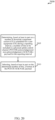
- a method for wireless communication may include determining, based at least in part on a number of downlink component carriers (CCs) scheduled for a user equipment (UE) during a reporting interval, a number of bits to be included in a physical uplink control channel (PUCCH) acknowledgement/non-acknowledgement (ACK/NAK) payload for the Document US2012/218881 relates to a method and system for feeding back an acknowledgement/negative-acknowledgement response on a physical uplink control channel and discloses that when LTE-A adopts carrier aggregation technology, and when the UE is configured with 4 downlink component carriers, the UE needs to feed back the ACK/NACK of these 4 downlink component carriers.
- CCs downlink component carriers
- UE user equipment
- NAK acknowledgement/non-acknowledgement
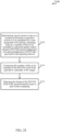
- the method may also include selecting, based at least in part on the determined number of bits, a format of the PUCCH ACK/NAK payload.
- selecting the format of the PUCCH ACK/NAK payload may include selecting one of a plurality of predefined formats for the PUCCH ACK/NAK payload, wherein the predefined formats for the PUCCH ACK/NAK payload include different combinations of: UE multiplexing densities within a resource block (RB), spreading factors, or numbers of RBs allocated per symbol period.
- each of the predefined formats for the PUCCH ACK/NAK payload may be based at least in part on a format including two reference signal symbol periods per slot.
- the selected format of the PUCCH ACK/NAK payload may be based at least in part on a format including two reference signal symbol periods per slot. In some examples of the method, the selected format of the PUCCH ACK/NAK payload may be further based at least in part on a format including one reference signal symbol per slot.
- selecting the format of the PUCCH ACK/NAK payload may include comparing the number of bits to be included in the PUCCH ACK/NAK payload to a plurality of bit ranges, and selecting the format of the PUCCH ACK/NAK payload based at least in part on the comparing.
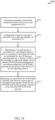
- the selected format of the PUCCH ACK/NAK payload may include a UE multiplexing density, within a RB, of at least four UEs.
- the selected format of the PUCCH ACK/NAK payload may include a UE multiplexing density, within a RB, of two UEs, and at least two groups of symbol periods.
- Each of the at least two groups of symbol periods may include at least one symbol, and spreading may be applied independently within each of the at least two groups of symbol periods.
- a spreading factor of three may be applied to a first group of three symbol periods
- a spreading factor of two may be applied to a second group of two symbol periods
- two of three orthogonal cover codes (OCCs) may be used when applying the spreading factor of three.
- OCCs orthogonal cover codes
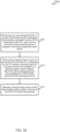
- a first spreading factor of two may be applied to a first group of one symbol period
- a second spreading factor of two may be applied to a second group of two symbol periods
- a third spreading factor of two may be applied to a third group of two symbol periods.
- the first spreading factor may be applied using a Walsh code or using elements of an orthogonal Fast Fourier Transform (FFT) matrix.
- FFT orthogonal Fast Fourier Transform
- each spreading factor of a plurality of spreading factors of two may be applied to a respective symbol period of a plurality of symbol periods.
- each spreading factor of the plurality of spreading factors of two may be applied using a Walsh code or using elements of an orthogonal FFT matrix.
- the selected format of the PUCCH ACK/NAK payload may include no UE multiplexing within a RB, no spreading factor, and an RB allocation per symbol period of one.
- the selected format of the PUCCH ACK/NAK payload may include no UE multiplexing within a RB, no spreading factor, and a RB allocation per symbol period of two.
- the selected format of the PUCCH ACK/NAK payload may include no UE multiplexing within a RB, no spreading factor, and a RB allocation per symbol period of three.
- the method may include identifying an allocation of a plurality of downlink CCs for the UE, and identifying a first subset of downlink CCs within the plurality of downlink CCs.
- the number of bits to be included in the PUCCH ACK/NAK payload may be identified for the first subset of downlink CCs.
- the PUCCH ACK/NAK payload may include a first PUCCH ACK/NAK payload
- the method may include identifying a second subset of downlink CCs within the plurality of downlink CCs, where the second subset of downlink CCs corresponds to a second PUCCH ACK/NAK payload.
- the method may further include transmitting the first PUCCH ACK/NAK payload on a first uplink CC, and transmitting the second PUCCH ACK/NAK payload on a second uplink CC. In some examples, the method may further include transmitting the first PUCCH ACK/NAK payload and the second PUCCH ACK/NAK payload on a same uplink CC.
- the method may include receiving, at the UE, a number of downlink grants indicating the downlink CCs scheduled for the UE, and receiving with each of the downlink grants a respective downlink assignment index (DAI).
- DAI downlink assignment index
- the respective DAI for a downlink grant may indicate a bit mapping and resource selection, in the PUCCH ACK/NAK payload, for acknowledging/non-acknowledging each transmission over each downlink CC scheduled in the downlink grant.
- the respective DAI for a downlink grant may include a sequence number indicating a relationship between at least one downlink CC scheduled in the downlink grant and at least one downlink CC scheduled in another downlink grant.
- the method may include determining, based at least in part on the sequence number, a bit mapping and resource selection, in the PUCCH ACK/NAK payload, for acknowledging/non-acknowledging each transmission over each downlink CC scheduled in the downlink grant.
- the method may include transmitting, from a base station to the UE, a plurality of downlink grants indicating the downlink CCs scheduled for the UE, and transmitting a plurality of DAIs.
- Each of the plurality of downlink grants may include a respective one of the DAIs in the plurality of DAIs.
- the plurality of DAIs may include a plurality of sequence numbers, and the method may further include introducing sequence discontinuities in the plurality of sequence numbers, to increase the number of bits to be included in the PUCCH ACK/NAK payload.
- the method may further include receiving the PUCCH ACK/NAK payload, and using a set of ACK/NAK bits in the PUCCH ACK/NAK payload, which set of ACK/NAK bits correspond to the sequence discontinuities, as a virtual cyclic redundancy check (CRC).
- CRC virtual cyclic redundancy check
- the method may include receiving, at the UE, an ACK/NAK resource indicator (ARI) identifying at least two different uplink CCs.
- the method may include receiving, at the UE, a number of downlink grants indicating the downlink CCs scheduled for the UE; and selecting the format of the PUCCH ACK/NAK payload may include selecting a format used to transmit the PUCCH ACK/NAK payload.
- the method may include transmitting, from a base station to the UE, a plurality of downlink grants indicating the downlink CCs scheduled for the UE; and selecting the format of the PUCCH ACK/NAK payload may include selecting a format used to decode the PUCCH ACK/NAK payload.
- the method may include configuring at least two groups of downlink CCs, and selecting the format of the PUCCH ACK/NAK payload may be performed for each of the at least two groups of downlink CCs. In some examples, the method may include configuring at least two groups of downlink CCs, and selecting the format of the PUCCH ACK/NAK payload may be performed considering bundling of ACK/NAK bits for the downlink CCs within each group of downlink CCs.
- an apparatus for wireless communication includes means for determining, based at least in part on a number of downlink CCs scheduled for UE during a reporting interval, a number of bits to be included in a PUCCH ACK/NAK payload for the reporting interval.
- the apparatus may also include means for selecting, based at least in part on the determined number of bits, a format of the PUCCH ACK/NAK payload.
- the apparatus may further include means for implementing one or more aspects of the method for wireless communication described above with respect to the first set of illustrative examples.
- the apparatus may include a processor, memory in electronic communication with the processor, and instructions stored in the memory.
- the instructions may be executable by the processor to determine, based at least in part on a number of downlink CCs scheduled for a UE during a reporting interval, a number of bits to be included in a PUCCH ACK/NAK payload for the reporting interval.
- the instructions may also be executable by the processor to select, based at least in part on the determined number of bits, a format of the PUCCH ACK/NAK payload.
- the instructions may also be executable by the processor to implement one or more aspects of the method for wireless communication described above with respect to the first set of illustrative examples.
- the non-transitory computer-readable medium may include instructions to determine, based at least in part on a number of downlink CCs scheduled for a UE during a reporting interval, a number of bits to be included in a PUCCH ACK/NAK payload for the reporting interval.
- the non-transitory computer-readable medium may also include instructions to select, based at least in part on the determined number of bits, a format of the PUCCH ACK/NAK payload.
- the non-transitory computer-readable medium may also include instructions to implement one or more aspects of the method for wireless communication described above with respect to the first set of illustrative examples.
- Specific examples described in the present disclosure enable up to 32 downlink CCs to be ACK'd or NAK'd in an LTE/LTE-A PUCCH ACK/NAK payload, and enable the format of the payload to be selected to optimize its use by multiple UEs or by a UE ACKing or NAKing transmissions over a greater number of downlink CCs.
- the techniques described in the present disclosure may also be used to select a PUCCH ACK/NAK payload format for ACKing or NAKing transmissions over any number of downlink CCs.
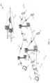
- FIG. 1 illustrates an example of a wireless communication system 100, in accordance with various aspects of the disclosure.
- the wireless communication system 100 may include base stations 105, UEs 115, and a core network 130.
- the core network 130 may provide user authentication, access authorization, tracking, Internet Protocol (IP) connectivity, and other access, routing, or mobility functions.
- IP Internet Protocol
- the base stations 105 may interface with the core network 130 through backhaul links 132 (e.g., S1, etc.) and may perform radio configuration and scheduling for communication with the UEs 115, or may operate under the control of a base station controller (not shown).
- the base stations 105 may communicate, either directly or indirectly (e.g., through core network 130), with each other over backhaul links 134 (e.g., X1, etc.), which may be wired or wireless communication links.
- backhaul links 134 e.g., X1, etc.
- the base stations 105 may wirelessly communicate with the UEs 115 via one or more base station antennas. Each of the base station 105 sites may provide communication coverage for a respective geographic coverage area 110.
- a base station 105 may be referred to as a base transceiver station, a radio base station, an access point, a radio transceiver, a NodeB, an eNodeB (eNB), a Home NodeB, a Home eNodeB, or some other suitable terminology.
- the geographic coverage area 110 for a base station 105 may be divided into sectors making up a portion of the coverage area (not shown).
- the wireless communication system 100 may include base stations 105 of different types (e.g., macro or small cell base stations). There may be overlapping geographic coverage areas 110 for different technologies.
- the wireless communication system 100 may include an LTE/LTE-A network.
- LTE/LTE-A networks the term evolved Node B (eNB) may be used to describe the base stations 105, while the term UE may be used to describe the UEs 115.
- the wireless communication system 100 may be a Heterogeneous LTE/LTE-A network in which different types of eNBs provide coverage for various geographical regions. For example, each eNB or base station 105 may provide communication coverage for a macro cell, a small cell, or other types of cell.
- cell is a 3GPP term that can be used to describe a base station, a carrier or component carrier associated with a base station, or a coverage area (e.g., sector, etc.) of a carrier or base station, depending on context.
- a macro cell may cover a relatively large geographic area (e.g., several kilometers in radius) and may allow unrestricted access by UEs with service subscriptions with the network provider.
- a small cell may be a lower-powered base station, as compared with a macro cell that may operate in the same or different (e.g., dedicated, shared, etc.) radio frequency spectrums as macro cells.
- Small cells may include pico cells, femto cells, and micro cells according to various examples.
- a pico cell may cover a relatively smaller geographic area and may allow unrestricted access by UEs with service subscriptions with the network provider.
- a femto cell also may cover a relatively small geographic area (e.g., a home) and may provide restricted access by UEs having an association with the femto cell (e.g., UEs in a closed subscriber group (CSG), UEs for users in the home, and the like).
- An eNB for a macro cell may be referred to as a macro eNB.
- An eNB for a small cell may be referred to as a small cell eNB, a pico eNB, a femto eNB or a home eNB.
- An eNB may support one or multiple (e.g., two, three, four, and the like) cells (e.g., component carriers).
- the wireless communication system 100 may support synchronous or asynchronous operation.
- the base stations may have similar frame timing, and transmissions from different base stations may be approximately aligned in time.
- the base stations may have different frame timing, and transmissions from different base stations may not be aligned in time.
- the techniques described herein may be used for either synchronous or asynchronous operations.
- the communication networks may be packet-based networks that operate according to a layered protocol stack.
- PDCP Packet Data Convergence Protocol
- a Radio Link Control (RLC) layer may perform packet segmentation and reassembly to communicate over logical channels.
- RLC Radio Link Control
- a Medium Access Control (MAC) layer may perform priority handling and multiplexing of logical channels into transport channels.
- the MAC layer may also use Hybrid ARQ (HARQ) to provide retransmission at the MAC layer to improve link efficiency.
- HARQ Hybrid ARQ
- the Radio Resource Control (RRC) protocol layer may provide establishment, configuration, and maintenance of an RRC connection between a UE 115 and the base stations 105 or core network 130 supporting radio bearers for the user plane data.
- RRC Radio Resource Control
- the transport channels may be mapped to physical channels.
- the UEs 115 may be dispersed throughout the wireless communication system 100, and each UE 115 may be stationary or mobile.
- a UE 115 may also include or be referred to by those skilled in the art as a mobile station, a subscriber station, a mobile unit, a subscriber unit, a wireless unit, a remote unit, a mobile device, a wireless device, a wireless communications device, a remote device, a mobile subscriber station, an access terminal, a mobile terminal, a wireless terminal, a remote terminal, a handset, a user agent, a mobile client, a client, or some other suitable terminology.
- a UE 115 may be a cellular phone, a personal digital assistant (PDA), a wireless modem, a wireless communication device, a handheld device, a tablet computer, a laptop computer, a cordless phone, a wireless local loop (WLL) station, or the like.
- PDA personal digital assistant
- a UE may be able to communicate with various types of base stations and network equipment, including macro eNBs, small cell eNBs, relay base stations, and the like.
- each communication link 125 may include one or more carriers, where each carrier may be a signal made up of multiple sub-carriers (e.g., waveform signals of different frequencies) modulated according to the various radio technologies described above. Each modulated signal may be sent on a different sub-carrier and may carry control information (e.g., reference signals, control channels, etc.), overhead information, user data, etc.
- the communication links 125 may transmit bidirectional communications using a frequency domain duplexing (FDD) operation (e.g., using paired spectrum resources) or a time domain duplexing (TDD) operation (e.g., using unpaired spectrum resources).
- FDD frequency domain duplexing
- TDD time domain duplexing
- base stations 105 or UEs 115 may include multiple antennas for employing antenna diversity schemes to improve communication quality and reliability between base stations 105 and UEs 115. Additionally or alternatively, base stations 105 or UEs 115 may employ multiple-input, multiple-output (MIMO) techniques that may take advantage of multi-path environments to transmit multiple spatial layers carrying the same or different coded data.
- MIMO multiple-input, multiple-output
- the wireless communication system 100 may support operation on multiple cells or carriers, a feature which may be referred to as carrier aggregation (CA) or dual-connectivity operation.
- a carrier may also be referred to as a component carrier (CC), a layer, a channel, etc.
- CC component carrier
- the terms “carrier,” “component carrier,” “cell,” and “channel” may be used interchangeably herein.
- a UE 115 may be configured with multiple downlink CCs and one or more uplink CCs for carrier aggregation. Carrier aggregation may be used with both FDD and TDD component carriers.
- downlink transmissions received by a UE on a plurality of downlink CCs may be acknowledged individually, on the same or different uplink CCs, or as part of a PUCCH ACK/NAK payload transmitted on one or more uplink CCs.
- the wireless communication system 100 may support operation over a dedicated radio frequency spectrum (e.g., a radio frequency spectrum for which transmitting apparatuses may not contend for access because the radio frequency spectrum is licensed to particular users for particular uses, such as a licensed radio frequency spectrum usable for LTE/LTE-A communications) or a shared radio frequency spectrum (e.g., a radio frequency spectrum for which transmitting apparatuses contend for access (e.g., a radio frequency spectrum that is available for unlicensed use, such as Wi-Fi use, or a radio frequency spectrum that is available for use by multiple operators in an equally shared or prioritized manner)).
- the downlink CCs and uplink CCs allocated to a UE may all be allocated over the dedicated radio frequency spectrum, all be allocated over the shared radio frequency spectrum, or be allocated over a combination of the dedicated radio frequency spectrum and the shared radio frequency spectrum.
- the communication links 125 shown in wireless communication system 100 may include downlink (DL) transmissions, from a base station 105 to a UE 115, or uplink (UL) transmissions, from a UE 115 to a base station 105.
- the downlink transmissions may also be called forward link transmissions, while the uplink transmissions may also be called reverse link transmissions.
- the downlink transmissions may include, for example, a physical downlink shared channel (PDSCH), a physical downlink control channel (PDCCH; e.g., for transmission over a dedicated radio frequency spectrum), or an enhanced PDCCH (EPDCCH; e.g., for transmission over a shared radio frequency spectrum).
- PDSCH physical downlink shared channel
- PDCCH physical downlink control channel
- EPDCCH enhanced PDCCH
- the uplink transmissions may include, for example, a physical uplink shared channel (PUSCH) or a physical uplink control channel (PUCCH).
- PUSCH physical uplink shared channel
- PUCCH physical uplink control channel
- downlink transmissions received by a UE on a PDSCH may be acknowledged (ACK'd) or non-acknowledged (NAK'd) by ACK/NAK bits transmitted in an uplink transmission over a PUCCH.
- ACK'd acknowledge
- NAK'd non-acknowledged
- a UE 115 may select a PUCCH format to transmit ACK/NAK messages based on the number of downlink CCs scheduled for the UE during a reporting interval. For example, the UE may determine a number of ACK/NAK bits to be included in a PUCCH payload for the reporting interval based at least in part on the number of downlink CCs scheduled for the reporting interval. Based on the determined number of bits, the UE 115 may select a PUCCH format. Examples of PUCCH frame types and techniques for selecting an appropriate PUCCH frame for a given reporting interval are explained in more detail below.
- FIG. 2 shows a wireless communication system 200 in which LTE/LTE-A may be deployed under different scenarios using a shared radio frequency spectrum, in accordance with various aspects of the present disclosure. More specifically, FIG. 2 illustrates examples of a supplemental downlink mode (also referred to as a licensed assisted access mode), a carrier aggregation mode, and a standalone mode in which LTE/LTE-A is deployed using a shared radio frequency spectrum.
- the wireless communication system 200 may be an example of portions of the wireless communication system 100 described with reference to FIG. 1 .
- a first base station 205 and a second base station 205-a may be examples of aspects of one or more of the base stations 105 described with reference to FIG.
- a first UE 215, a second UE 215-a, a third UE 215-b, and a fourth UE 215-c may be examples of aspects of one or more of the UEs 115 described with reference to FIG. 1 .
- the first base station 205 may transmit OFDMA waveforms to the first UE 215 using a downlink channel 220.
- the downlink channel 220 may be associated with a frequency F1 in a shared radio frequency spectrum.
- the first base station 205 may transmit OFDMA waveforms to the first UE 215 using a first bidirectional link 225 and may receive SC-FDMA waveforms from the first UE 215 using the first bidirectional link 225.
- the first bidirectional link 225 may be associated with a frequency F4 in a dedicated radio frequency spectrum.
- the downlink channel 220 in the shared radio frequency spectrum and the first bidirectional link 225 in the dedicated radio frequency spectrum may operate contemporaneously.
- the downlink channel 220 may provide a downlink capacity offload for the first base station 205.
- the downlink channel 220 may be used for unicast services (e.g., addressed to one UE) or for multicast services (e.g., addressed to several UEs). This scenario may occur with any service provider (e.g., a mobile network operator (MNO)) that uses a dedicated radio frequency spectrum and desires to relieve some of the traffic or signaling congestion.
- MNO mobile network operator
- the first base station 205 may transmit OFDMA waveforms to the second UE 215-a using a second bidirectional link 230 and may receive OFDMA waveforms, SC-FDMA waveforms, or resource block interleaved FDMA waveforms from the second UE 215-a using the second bidirectional link 230.
- the second bidirectional link 230 may be associated with the frequency F1 in the shared radio frequency spectrum.
- the first base station 205 may also transmit OFDMA waveforms to the second UE 215-a using a third bidirectional link 235 and may receive SC-FDMA waveforms from the second UE 215-a using the third bidirectional link 235.
- the third bidirectional link 235 may be associated with a frequency F2 in a dedicated radio frequency spectrum.
- the second bidirectional link 230 may provide a downlink and uplink capacity offload for the first base station 205.
- this scenario may occur with any service provider (e.g., MNO) that uses a dedicated radio frequency spectrum and desires to relieve some of the traffic or signaling congestion.
- MNO service provider
- the first base station 205 may transmit OFDMA waveforms to the third UE 215-b using a fourth bidirectional link 240 and may receive OFDMA waveforms, SC-FDMA waveforms, or resource block interleaved waveforms from the third UE 215-b using the fourth bidirectional link 240.
- the fourth bidirectional link 240 may be associated with a frequency F3 in the shared radio frequency spectrum.
- the first base station 205 may also transmit OFDMA waveforms to the third UE 215-b using a fifth bidirectional link 245 and may receive SC-FDMA waveforms from the third UE 215-b using the fifth bidirectional link 245.
- the fifth bidirectional link 245 may be associated with the frequency F2 in the dedicated radio frequency spectrum.
- the fourth bidirectional link 240 may provide a downlink and uplink capacity offload for the first base station 205.
- This example and those provided above are presented for illustrative purposes and there may be other similar modes of operation or deployment scenarios that combine LTE/LTE-A in a dedicated radio frequency spectrum and use a shared radio frequency spectrum for capacity offload.
- an operational example may include a bootstrapped mode (e.g., supplemental downlink (e.g., licensed assisted access), carrier aggregation) that uses the LTE/LTE-A primary component carrier (PCC) on the dedicated radio frequency spectrum and at least one secondary component carrier (SCC) on the shared radio frequency spectrum.
- a bootstrapped mode e.g., supplemental downlink (e.g., licensed assisted access), carrier aggregation
- PCC primary component carrier
- SCC secondary component carrier
- data and control may, for example, be communicated in the dedicated radio frequency spectrum (e.g., via first bidirectional link 225, third bidirectional link 235, and fifth bidirectional link 245) while data may, for example, be communicated in the shared radio frequency spectrum (e.g., via second bidirectional link 230 and fourth bidirectional link 240).
- the carrier aggregation mechanisms supported when using a shared radio frequency spectrum may fall under a hybrid frequency division duplexing-time division duplexing (FDD-TDD) carrier aggregation or a TDD-TDD carrier aggregation with different symmetry across component carriers.
- FDD-TDD hybrid frequency division duplexing-time division duplexing
- the second base station 205-a may transmit OFDMA waveforms to the fourth UE 215-c using a bidirectional link 250 and may receive OFDMA waveforms, SC-FDMA waveforms, or resource block interleaved FDMA waveforms from the fourth UE 215-c using the bidirectional link 250.
- the bidirectional link 250 may be associated with the frequency F3 in the shared radio frequency spectrum.
- the standalone mode may be used in non-traditional wireless access scenarios, such as in-stadium access (e.g., unicast, multicast).
- An example of a type of service provider for this mode of operation may be a stadium owner, cable company, event host, hotel, enterprise, or large corporation that does not have access to a dedicated radio frequency spectrum.
- a transmitting apparatus such as one of the base stations 105, 205, or 205-a described with reference to FIG. 1 or 2 , or one of the UEs 115, 215, 215-a, 215-b, or 215-c described with reference to FIG. 1 or 2 , may use a gating interval to gain access to a channel of a shared radio frequency spectrum (e.g., to a physical channel of the shared radio frequency spectrum).
- the gating interval may be periodic.
- the periodic gating interval may be synchronized with at least one boundary of an LTE/LTE-A radio interval.
- the gating interval may define the application of a contention-based protocol, such as an LBT protocol based on the LBT protocol specified in European Telecommunications Standards Institute (ETSI) (EN 301 893).
- ETSI European Telecommunications Standards Institute
- the gating interval may indicate when a transmitting apparatus is to perform a contention procedure (e.g., an LBT procedure) such as a clear channel assessment (CCA) procedure.
- CCA clear channel assessment
- the outcome of the CCA procedure may indicate to the transmitting apparatus whether a channel of a shared radio frequency spectrum is available or in use for the gating interval (also referred to as an LBT radio frame).
- the transmitting apparatus may reserve or use the channel of the shared radio frequency spectrum during part or all of the LBT radio frame.
- the transmitting apparatus may be prevented from using the channel during the LBT radio frame.
- FIG. 3 shows a wireless communication system 300 in which LTE/LTE-A may be deployed in a carrier aggregation scenario, in accordance with various aspects of the present disclosure.
- the wireless communication system 300 may be an example of portions of the wireless communication system 100 or 200 described with reference to FIG. 1 or 2 .
- a base station 305 may be an example of aspects of one or more of the base stations 105, 205, or 205-a described with reference to FIG. 1 or 2
- a UE 315 may be an examples of aspects of one or more of the UEs 115, 215, 215-a, 215-b, or 215-c described with reference to FIG. 1 or 2 .
- the UE 315 When communicating in a carrier aggregation mode using LTE/LTE-A communications, the UE 315 has traditionally communicated with the base station 305 using up to five component carriers. However, techniques described in the present disclosure can increase the size of a PUCCH ACK/NAK payload to allow communication over up to 32 component carriers.
- One of the component carriers may be designated as a primary component carrier, and the remaining component carriers may be designated as secondary component carriers.
- Each component carrier may be configured as a downlink component carrier, an uplink component carrier, or a cell (e.g., a component carrier that may be configured for use as a downlink component carrier and/or an uplink component carrier).
- first downlink component carrier 320 a first downlink component carrier 320, a second downlink component carrier 325, a third downlink component carrier 330, a first uplink component carrier 335, and a second uplink component carrier 340.
- first downlink component carrier 320, the second downlink component carrier 325, the third downlink component carrier 330, the first uplink component carrier 335, and the second uplink component carrier 340 may operate in a dedicated radio frequency spectrum or a shared radio frequency spectrum, depending on how the component carrier is allocated or configured.
- the UE 315 When the UE 315 is configured for operation in a supplemental downlink mode of operation using a shared radio frequency spectrum, as described with reference to FIG. 2 , and when the UE 315 is operating in a carrier aggregation mode, one or more of the first downlink component carrier 320, the second downlink component carrier 325, and the third downlink component carrier 330 may operate in the licensed radio frequency spectrum band; one or more of the first downlink component carrier 320, the second downlink component carrier 325, and the third downlink component carrier 330 may operate in the shared radio frequency spectrum; and the first uplink component carrier 335 and the second uplink component carrier 340 may operate in the dedicated radio frequency spectrum.
- one or more of the first downlink component carrier 320, the second downlink component carrier 325, and the third downlink component carrier 330 may operate in the dedicated radio frequency spectrum; one or more of the first downlink component carrier 320, the second downlink component carrier 325, and the third downlink component carrier 330 may operate in the shared radio frequency spectrum; one or more of the first uplink component carrier 335 and the second uplink component carrier 340 may operate in the dedicated radio frequency spectrum band; and one or more of the first uplink component carrier 335 and the second uplink component carrier 340 may operate in the shared radio frequency spectrum.
- all of the downlink component carriers may operate in the dedicated radio frequency spectrum, or all of the uplink component carriers may operate in the shared radio frequency spectrum, but not all of the downlink component carriers and all of the uplink component carriers may operate in the shared radio frequency spectrum (e.g., at least one downlink component carrier or at least one uplink component carrier operates in the dedicated radio frequency spectrum).
- the UE 315 When the UE 315 is configured for operation in a standalone mode of operation using the shared radio frequency spectrum, as described with reference to FIG. 2 , and when the UE 315 is operating in a carrier aggregation mode, all of the first downlink component carrier 320, the second downlink component carrier 325, the third downlink component carrier 330, the first uplink component carrier 335, and the second uplink component carrier 340 may operate in the shared radio frequency spectrum.
- FIG. 4 shows an exemplary resource block (RB) of a PUCCH, which RB may be transmitted or received during a subframe 400, in accordance with various aspects of the present disclosure.
- the RB may be transmitted by one or more of the UEs 115, 215, 215-a, 215-b, 215-c, or 315 described with reference to FIG. 1 , 2 , or 3 , or transmitted by one or more of the base stations 105, 205, 205-a, or 305 described with reference to FIG. 1 , 2 , or 3 .
- the subframe 400 includes a first slot 405 (e.g., Slot 0) and a second slot 410 (e.g., Slot 1), with each slot being configured for operation in an LTE/LTE-A normal cyclic prefix (CP) mode and including seven symbol periods numbered 0, 1, 2, 3, 4, 5, and 6.
- Demodulation reference signals (DM-RSs) may be transmitted in the subframe in accordance with an LTE/LTE-A PUCCH Format 3for normal CP (e.g., during symbol periods 1 and 5 of each slot of the subframe).
- DM-RSs Demodulation reference signals
- the present disclosure describes how a slot of the subframe 400 may be formatted for the transmission or reception of PUCCH ACK/NAK payloads of varying size.
- FIG. 5 shows an exemplary RB of a PUCCH, which RB may be transmitted or received during a subframe 500, in accordance with various aspects of the present disclosure.
- the RB may be transmitted by one or more of the UEs 115, 215, 215-a, 215-b, 215-c, or 315 described with reference to FIG. 1 , 2 , or 3 , or transmitted by one or more of the base stations 105, 205, 205-a, or 305 described with reference to FIG. 1 , 2 , or 3 .
- the subframe 500 includes a first slot 505 (e.g., Slot 0) and a second slot 510 (e.g., Slot 1), with each slot being configured for operation in an LTE/LTE-A extended CP mode and including six symbol periods numbered 0, 1, 2, 3, 4, and 5.
- Demodulation reference signals DM-RSs
- DM-RSs may be transmitted in the subframe in accordance with an LTE/LTE-A PUCCH Format 3 for extended CP (e.g., during symbol period 3 of each slot of the subframe).
- the present disclosure describes how a slot of the subframe 500 may be formatted for the transmission or reception of PUCCH ACK/NAK payloads of varying size.
- FIGS. 6-10 describe various PHY layer designs for a PUCCH. More particularly, FIG. 6 shows an exemplary table 600 of predetermined formats of a PUCCH ACK/NAK payload, from which a format of a PUCCH ACK/NAK payload may be selected by a UE or base station, for a reporting interval, in accordance with various aspects of the present disclosure.
- a UE such as one of the UEs 115, 215, 215-a, 215-b, 215-c, or 315 described with reference to FIG. 1 , 2 , or 3 , the UE may select one of the formats for transmitting a PUCCH ACK/NAK payload for a reporting interval.
- the base station may select one of the formats for decoding the PUCCH ACK/NAK payload.
- FIG. 6 shows five exemplary formats of a PUCCH ACK/NAK payload, from which a UE or base station may select a format, for a reporting interval, based at least in part on a number of bits to be included in a PUCCH ACK/NAK payload for the reporting interval.
- the number of bits to be included in the PUCCH ACK/NAK payload may be determined based at least in part on a number of downlink CCs scheduled for the UE during the reporting interval.
- the predefined formats for the PUCCH ACK/NAK payload may include different combinations of: UE multiplexing densities within a RB, spreading factors, or numbers of RBs allocated per symbol period.
- a first format 605 of the PUCCH ACK/NAK payload may include a UE multiplexing density, within a RB, of at least four UEs (e.g., four or five UEs).
- the first format may employ a Dual Reed-Muller (Dual RM) coding of its payload.
- the first format may be selected, for example, when the number of bits to be included in an ACK/NAK payload is 21 or fewer bits (or from 1 to 21 bits) and a RB is configured as described with reference to FIG. 4 or 5 .
- a second format 610 of the PUCCH ACK/NAK payload may include a UE multiplexing density, within a RB, of two UEs.
- the second format may also include at least two groups of symbol periods, where each of the at least two groups of symbol periods includes at least one symbol, and where spreading is applied independently within each of the at least two groups of symbol periods.
- the second format may encode its payload using Tail-Biting Convolutional Coding (TBCC).
- TBCC Tail-Biting Convolutional Coding
- the second format may be selected, for example, when the number of bits to be included in the ACK/NAK payload is 60 or fewer bits (or from 22 to 60 bits) and a RB is configured as described with reference to FIG. 4 or 5 .
- a third format 615 of the PUCCH ACK/NAK payload may include no UE multiplexing within a RB, no spreading factor, and an RB allocation per symbol period of one.
- the third format may encode its payload using TBCC or Turbo coding.
- the third format may be selected, for example, when the number of bits to be included in the ACK/NAK payload is 120 or fewer bits (or from 61 to 120 bits) and a RB is configured as described with reference to FIG. 4 or 5 .
- a fourth format 620 of the PUCCH ACK/NAK payload may include no UE multiplexing within a RB, no spreading factor, and an RB allocation per symbol period of two.
- the fourth format may encode its payload using TBCC or Turbo coding.
- the fourth format may be selected, for example, when the number of bits to be included in the ACK/NAK payload is 240 or fewer bits (or from 121 to 240 bits) and a RB is configured as described with reference to FIG. 4 or 5 .
- a fifth format 625 of the PUCCH ACK/NAK payload may include no UE multiplexing within a RB, no spreading factor, and an RB allocation per symbol period of three.
- the fifth format may encode its payload using TBCC or Turbo coding.
- the fifth format may be selected, for example, when the number of bits to be included in the ACK/NAK payload is 360 or fewer bits (or from 241 to 360 bits) and a RB is configured as described with reference to FIG. 4 or 5 .
- Each format of a PUCCH ACK/NAK payload shown in FIG. 6 may have an LTE/LTE-A PUCCH Format 3 reference signal symbol structure. That is, for example, when a PUCCH ACK/NAK payload is transmitted using a normal cyclic prefix (CP), the format of the PUCCH ACK/NAK payload may have two reference signal symbol periods per slot of a subframe; and when a PUCCH ACK/NAK payload is transmitted using an extended CP, the format of the PUCCH ACK/NAK payload may have one reference signal symbol per slot of a subframe.
- the reference signals transmitted in the reference signal symbol periods may include demodulation reference signals (DM-RSs).
- Each format of a PUCCH ACK/NAK payload that has no spreading factor may have a data structure similar to that of a PUSCH. Processing of a PUCCH ACK/NAK payload transmitted using one of the third format 615, the fourth format 620, or the fifth format 625 may therefore be similar to the processing of an LTE/LTE-A PUSCH.
- FIGS. 7-9 illustrate various examples of the second format 610 of a PUCCH ACK/NAK payload shown in FIG. 6 .
- FIG. 7 shows a format 700 of a PUCCH ACK/NAK payload in which a spreading factor of three (SF3) may be applied to a first group 710 of three symbol periods and a spreading factor of two (SF2) may be applied to a second group 715 of two symbol periods, in accordance with various aspects of the present disclosure.
- the groups of symbol periods are shown to be symbol periods in a slot 705 of a subframe transmitted using a normal CP.
- the first group of three symbol periods and the second group of two symbol periods could be groups of symbol periods in a slot of a subframe transmitted using an extended CP.
- the first group 710 of three symbol periods is shown to include symbol periods 0, 2, and 3
- the second group 715 of two symbol periods is shown to include symbol periods 4 and 6.
- OCCs orthogonal cover codes
- SNR signal-to-noise-ratio
- FIG. 8 shows a format 800 of a PUCCH ACK/NAK payload in which a first spreading factor of two (SF2) may be applied to a first group 810 of one symbol period, a second spreading factor of two (SF2) may be applied to a second group 815 of two symbol periods, and a third spreading factor of two (SF2) may be applied within a third group 820 of two symbol periods, in accordance with various aspects of the present disclosure.
- the groups of symbol periods are shown to be symbol periods in a slot 805 of a subframe transmitted using a normal CP.
- the groups could be groups of symbol periods in a slot of a subframe transmitted using an extended CP.
- the first group 810 of one symbol period is shown to include symbol period 0, the second group 815 of two symbol periods is shown to include symbol periods 2 and 3, and the third group 820 of two symbol periods is shown to include symbol periods 4 and 6.
- the first spreading factor may be applied using a Walsh code (e.g., a block of six data symbols may be repeated once and a Walsh code W2 (e.g., [++ for a first UE, and +- for a second UE]) may be used on the repetitions for spreading before applying a Discrete Fourier Transform (DFT) to the data symbols) or using elements of an orthogonal Fast Fourier Transform (FFT) matrix (e.g., a block of six data symbols may be repeated once and a code of 1 , 1 , ... , 1 ; 1 , e ⁇ 2 ⁇ i 12 , e ⁇ 2 ⁇ 2 ⁇ i 12 , ... , e ⁇ 11 ⁇ 2 ⁇ i 12 may be used on the repetitions for
- FIG. 9 shows a format 900 of a PUCCH ACK/NAK payload in which each spreading factor (SF2) of a plurality of spreading factors of two is applied to a respective groups 910, 915, 920, 925, and 930 of one symbol period, in accordance with various aspects of the present disclosure.
- the groups of symbol periods are shown to be symbol periods in a slot of a subframe transmitted using a normal CP.
- the first group of three symbol periods and the second group of two symbol periods could be groups of symbol periods in a slot 905 of a subframe transmitted using an extended CP.
- each spreading factor of two may be applied using a Walsh code (e.g., a block of six data symbols may be repeated once and a Walsh code W2 (e.g., [++ for a first UE, and +- for a second UE]) may be used on the repetitions for spreading before applying a DFT to the data symbols) or using elements of an orthogonal FFT matrix (e.g., a block of six data symbols may be repeated once and a code of [ 1 , 1 , ... , 1 ; 1 , e ⁇ 2 ⁇ i 12 , e ⁇ 2 ⁇ 2 ⁇ i 12 , ... , e ⁇ 11 ⁇ 2 ⁇ i 12 ] may be used on the repetitions for spreading before applying a DFT to the data symbols).
- a Walsh code e.g., a block of six data symbols may be repeated once and a Walsh code W2 (e.g., [++ for a first UE, and +- for a second UE]) may be
- FIG. 10 shows an application of a spreading factor of two to data symbols (e.g., quadrature phase-shift keying (QPSK) symbols) within a symbol period, using a Walsh code, in accordance with various aspects of the present disclosure.
- the application shown may be used, for example, to apply the spreading factor of two to the first group of one symbol period described with reference to FIG. 8 or, individually, to any of the groups of one symbol period described with reference to FIG. 9 .
- a block 1005 of six data symbols may be repeated once (as block 1010) and a Walsh code W2 (e.g., [++ for a first UE, and +- for a second UE]) may be used on the repetitions for spreading before applying a DFT 1015 to the data symbols).
- Tone mapping may then be performed using an Inverse FFT (IFFT) 1020.
- IFFT Inverse FFT
- orthogonal resources may be allocated for each antenna port of a UE.
- a space-time block code STBC
- TxDiv transmission diversity
- four orthogonal DM-RS resources may be allocated for the second format 610 of a PUCCH ACK/NAK payload, and two orthogonal DM-RS resources may be allocated for the third format 615, fourth format 620, or fifth format 625 of a PUCCH ACK/NAK payload.
- the transmitted SC-FDM data symbols would be [ Y 0 , Y 1 , Y 2 , Y 3 , Y 4 ] (ignoring DM-RS symbol periods).
- the transmitted SC-FDM data symbols may be, for example, Y 0 Y 1 ⁇ Y 2 Y 3 ⁇ Y 4 for Antenna port 0, and Y 1 , ⁇ Y 0 ⁇ , Y 3 , ⁇ Y 2 ⁇ , Y 4 for Antenna port 1.
- the PHY layer designs for a PUCCH described in FIGS. 6-10 may be extended to PUCCH higher order modulation (e.g., 16 quadrature amplitude modulation (QAM)) or MIMO.
- PUCCH higher order modulation e.g., 16 quadrature amplitude modulation (QAM)
- QAM quadrature amplitude modulation
- MIMO multiple DM-RS resources per UE may be appropriate (e.g., similar to what was described above in the context of TxDiv).
- Higher order modulation and MIMO can increase the supportable PUCCH ACK/NAK payload without reducing UE multiplexing density.
- the downlink CCs allocated to a UE may be grouped into two or more subsets for the purpose of feedback reporting (e.g., for the purpose of ACK/NAK reporting).
- a number of bits to be included in a PUCCH ACK/NAK, payload for each group of downlink CCs may then be determined for a reporting interval, based at least in part on the number of downlink CCs in scheduled for the UE during the reporting interval; and based at least in part on the determined number of bits for each subset, a format of a PUCCH ACK/NAK payload for the subset may be selected.
- the format of each PUCCH ACK/NAK payload may be selected from a set of predefined formats such as the set of formats described with reference to FIG. 6 .
- a separate set of resources may be allocated for each PUCCH ACK/NAK payload.
- a first PUCCH ACK/NAK payload for a first group of downlink CCs may be transmitted on a first uplink CC
- an additional PUCCH ACK/NAK payload e.g., a second ACK/NAK payload
- an additional PUCCH ACK/NAK payload e.g., a second ACK/NAK payload
- the first PUCCH ACK/NAK payload and the additional PUCCH ACK/NAK payload (e.g., the second ACK/NAK payload) may be transmitted on a same uplink CC.
- the PUCCH design may be similar to that of a PUCCH transmitted on a secondary cell (SCell) in a dual connectivity scenario (but possibly with more than two groups of downlink CCs).
- SCell secondary cell
- the PUCCH ACK/NAK payloads may be transmitted using a non-SC-FDM waveform.
- the transmission of different PUCCH ACK/NAK payloads on the same uplink CC may be supported for formats of PUCCH ACK/NAK payload limited to one RB (e.g., the first format 605, the second format 610, and the third format 615 described with reference to FIG. 6 ).
- downlink assignment indices may be used for bit mapping and resource selection within a PUCCH ACK/NAK payload.
- a DAI may be associated (e.g., transmitted) with each of a number of downlink grants transmitted to a UE.
- the downlink grants may indicate the downlink CCs scheduled for a UE, and the DAI for a downlink grant may indicate a bit mapping and resource selection, in a PUCCH ACK/NAK payload, for acknowledging/non-acknowledging each transmission over each downlink CC scheduled in the downlink grant.
- each downlink CC may be associated with a unique DAI.
- a DAI per grant may apply to multiple downlink CCs, and a DAI for each of the multiple downlink CCs may be implicitly derived.
- a DAI may indicate a bit location across CCs and subframes.
- a DAI for a downlink grant may include a sequence number indicating a relationship between at least one downlink CC scheduled in the downlink grant and at least one downlink CC scheduled in another downlink grant.
- a bit mapping and resource selection for acknowledging/non-acknowledging a downlink CC (or downlink CCs) in a PUCCH ACK/NAK payload may be determined based at least in part on the sequence number.
- the sequence number may be a number generated by an n-bit counter, where n is incremented across CCs first and subframes second, with a cyclic wrap-around.
- Bit mapping may directly follow DAI processing when the DAI is an absolute ACK/NAK bit location indicator. Bit mapping may follow DAI processing, including unwrapping, when the DAI includes a sequence number.
- the set of sequence numbers received by a UE for a reporting interval may be used to determine the total number of downlink CCs, N, that are scheduled for the UE in the reporting interval.
- N the total number of downlink CCs
- a UE may select the smallest PUCCH ACK/NAK payload format that supports 2N bits.
- RRC-configured bundling for sets of downlink CCs or subframes may be factored into the N or 2N numbers.
- the omission of feedback for some downlink CCs may also be factored into the N or 2N numbers.
- a UE may not receive or properly decode one or more downlink grants.
- a non-received or improperly decoded downlink grant is transmitted to the UE before another downlink grant, which other downlink grant is received by the UE and associated with a sequence number following the sequence number of the non-received or improperly decoded downlink grant, the UE may use the sequence number(s) it receives to determine how many downlink grants it should have received and, in some cases, select the correct PUCCH ACK/NAK payload format based on a determination of the number of bits that the UE is supposed to acknowledge/non-acknowledge in the PUCCH ACK/NAK payload.
- a base station may introduce sequence discontinuities into the sequence numbers associated with a plurality of DAIs.
- the sequence discontinuities may serve to pad the sequence numbers, such that a LTE will be caused to determine a value of N or 2N that is large enough to cause selection of the appropriate PUCCH ACK/NAK format - even when one or more last-transmitted downlink grants are not received and the UE therefore determines an incorrect value of N or 2N.
- a base station When introducing sequence discontinuities into (or padding) a set of sequence numbers, a base station knows where the sequence discontinuities are introduced, and thus can expect NAKs for the PUCCH ACK/NAK payload bit positions corresponding to the sequence discontinuities. Given this expectation, the base station can use the introduced sequence discontinuities as a virtual cyclic redundancy check (CRC).
- CRC virtual cyclic redundancy check
- a base station may also introduce additional sequence discontinuities for the purpose of increasing the length of the CRC.
- a base station may associate an ACK/NAK Resource Indicator (ARI) with each downlink grant transmitted to a UE.
- ARI may be a 4-bit value indicating which of sixteen different PUCCH resources are to be used for ACK/NAK reporting.
- the different PUCCH resources may be associated with different uplink CCs (e.g., 10 PUCCH resources may be configured on an uplink CC1 and PUCCH resources may be configured on an uplink CC2).
- Each of the PUCCH resources may be configured (or may be expected to be configured) using the same PUCCH ACK/NAK format.
- an ARI may have a variable length, so that the length of the ARI may be tailored to the number of downlink CCs that are scheduled for a UE during a reporting interval. For example, when a UE is scheduled on 8 downlink CCs with 8 downlink grants, each of the first four downlink grants may be associated with an ARI value of a , and each of the second four downlink grants may be associated with an ARI value of b. Upon the UE detecting the change in ARI value, the UE may concatenate the ARI values in order of CC identity (CC_ID) to derive the 8-bit value ab. Unless the UE fails to receive four consecutive downlink grants, the appropriate PUCCH resource will be used.
- CC_ID CC identity
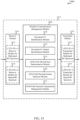
- FIG. 11 shows a block diagram 1100 of an apparatus 1115 for use in wireless communication, in accordance with various aspects of the present disclosure.
- the apparatus 1115 may be an example of aspects of one or more of the UEs 115, 215, 215-a, 215-b, 215-c, or 315 described with reference to FIG. 1 , 2 , or 3 , or aspects of one or more of the base stations 105, 205, 205-a, or 305 described with reference to FIG. 1 , 2 , or 3 .
- the apparatus 1115 may also be or include a processor.
- the apparatus 1115 may include a receiver module 1110, a wireless communication management module 1120, or a transmitter module 1130. Each of these modules may be in communication with each other.
- the modules of the apparatus 1115 may, individually or collectively, be implemented using one or more application-specific integrated circuits (ASICs) adapted to perform some or all of the applicable functions in hardware. Alternatively, the functions may be performed by one or more other processing units (or cores), on one or more integrated circuits. In other examples, other types of integrated circuits may be used (e.g., Structured/Platform ASICs, Field Programmable Gate Arrays (FPGAs), and other Semi-Custom ICs), which may be programmed in any manner known in the art.
- the functions of each module may also be implemented, in whole or in part, with instructions embodied in a memory, formatted to be executed by one or more general or application-specific processors.
- the receiver module 1110 may include at least one radio frequency (RF) receiver, such as at least one RF receiver operable to receive transmissions over a dedicated radio frequency spectrum or a shared radio frequency spectrum.
- the dedicated radio frequency spectrum may include a radio frequency spectrum for which transmitting apparatuses may not contend for access (e.g., a radio frequency spectrum licensed to particular users for particular uses, such as a licensed radio frequency spectrum usable for LTE/LTE-A communications).
- the shared radio frequency spectrum may include a radio frequency spectrum for which transmitting apparatuses contend for access (e.g., a radio frequency spectrum that is available for unlicensed use, such as Wi-Fi use, or a radio frequency spectrum that is available for use by multiple operators in an equally shared or prioritized manner).
- the dedicated radio frequency spectrum or the shared radio frequency spectrum may be used for LTE/LTE-A communications, as described, for example, with reference to FIG. 1 , 2 , or 3 .
- the receiver module 1110 may be used to receive various types of data or control signals (i.e., transmissions) over one or more communication links of a wireless communication system, such as one or more communication links of the wireless communication system 100, 200, or 300 described with reference to FIG. 1 , 2 , or 3 .
- the communication links may be established over the dedicated radio frequency spectrum or the shared radio frequency spectrum.
- the transmitter module 1130 may include at least one RF transmitter, such as at least one RF transmitter operable to transmit over the dedicated radio frequency spectrum or the shared radio frequency spectrum.
- the transmitter module 1130 may be used to transmit various types of data or control signals (i.e., transmissions) over one or more communication links of a wireless communication system, such as one or more communication links of the wireless communication system 100, 200, or 300 described with reference to FIG. 1 , 2 , or 3 .
- the communication links may be established over the dedicated radio frequency spectrum or the shared radio frequency spectrum.
- the wireless communication management module 1120 may be used to manage one or more aspects of wireless communication for the apparatus 1115.
- the wireless communication management module 1120 may include an ACK/NAK payload size determination module 1135 or an ACK/NAK payload format selection module 1140.
- the ACK/NAK payload size determination module 1135 may be used to determine, based at least in part on a number of downlink CCs scheduled for a UE during a reporting interval, a number of bits to be included in a PUCCH ACK/NAK payload for the reporting interval.
- the ACK/NAK payload format selection module 1140 may be used to select, based at least in part on the determined number of bits, a format of the PUCCH ACK/NAK payload.
- the ACK/NAK payload format selection module 1140 may select the format of the PUCCH ACK/NAK payload by selecting one of a plurality of predefined formats for the PUCCH ACK/NAK payload.
- the predefined formats for the PUCCH ACK/NAK payload may include, for example, different combinations of: UE multiplexing densities within a RB, spreading factors, or numbers of RBs allocated per symbol period.
- each of the predefined formats for the PUCCH ACK/NAK payload may be based at least in part on a format including two reference signal symbol periods per slot (e.g., when the predefined formats are configured for transmissions, in a slot of a subframe, with a normal CP). In some examples, each of the predefined formats for the PUCCH ACK/NAK payload may be based at least in part on a format including one reference signal symbol period per slot (e.g., when the predefined formats are configured for transmissions, in a slot of a subframe, with an extended CP).
- the wireless communication management module 1120 may receive a number of downlink grants indicating the downlink CCs scheduled for the UE.
- the ACK/NAK payload format selection module 1140 may select a PUCCH ACK/NAK payload format for transmitting the PUCCH ACK/NAK payload.
- the wireless communication management module 1120 may transmit, to a UE, a plurality of downlink grants indicating the downlink CCs scheduled for the UE.
- the ACK/NAK payload format selection module 1140 may select a PUCCH ACK/NAK payload format for decoding the PUCCH ACK/NAK payload.
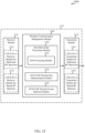
- FIG. 12 shows a block diagram 1200 of an apparatus 1215 for use in wireless communication, in accordance with various aspects of the present disclosure.
- the apparatus 1215 may be an example of aspects of one or more of the UEs 115, 215, 215-a, 215-b, 215-c, or 315 described with reference to FIG. 1 , 2 , or 3 , aspects of one or more of the base stations 105, 205, 205-a, or 305 described with reference to FIG. 1 , 2 , or 3 , or aspects of the apparatus 1115 described with reference to FIG. 11 .
- the apparatus 1215 may also be or include a processor.
- the apparatus 1215 may include a receiver module 1210, a wireless communication management module 1220, or a transmitter module 1230. Each of these modules may be in communication with each other.
- the modules of the apparatus 1215 may, individually or collectively, be implemented using one or more ASICs adapted to perform some or all of the applicable functions in hardware. Alternatively, the functions may be performed by one or more other processing units (or cores), on one or more integrated circuits. In other examples, other types of integrated circuits may be used (e.g., Structured/Platform ASICs, FPGAs, and other Semi-Custom ICs), which may be programmed in any manner known in the art.
- the functions of each module may also be implemented, in whole or in part, with instructions embodied in a memory, formatted to be executed by one or more general or application-specific processors.
- the receiver module 1210 may include at least one RF receiver, such as at least one RF receiver operable to receive transmissions over a dedicated radio frequency spectrum or a shared radio frequency spectrum.
- the dedicated radio frequency spectrum may include a radio frequency spectrum for which transmitting apparatuses may not contend for access (e.g., a radio frequency spectrum licensed to particular users for particular uses, such as a licensed radio frequency spectrum usable for LTE/LTE-A communications).
- the shared radio frequency spectrum may include a radio frequency spectrum for which transmitting apparatuses contend for access (e.g., a radio frequency spectrum that is available for unlicensed use, such as Wi-Fi use, or a radio frequency spectrum that is available for use by multiple operators in an equally shared or prioritized manner).
- the dedicated radio frequency spectrum or the shared radio frequency spectrum may be used for LTE/LTE-A communications, as described, for example, with reference to FIG. 1 , 2 , or 3 .
- the receiver module 1210 may in some cases include separate receivers for the dedicated radio frequency spectrum and the shared radio frequency spectrum.
- the separate receivers may, in some examples, take the form of an LTE/LTE-A receiver module for communicating over the dedicated radio frequency spectrum (e.g., LTE/LTE-A receiver module for dedicated RF spectrum 1212), and an LTE/LTE-A receiver module for communicating over the shared radio frequency spectrum (e.g., LTE/LTE-A receiver module for shared RF spectrum 1214).
- the receiver module 1210 including the LTE/LTE-A receiver module for dedicated RF spectrum 1212 or the LTE/LTE-A receiver module for shared RF spectrum 1214, may be used to receive various types of data or control signals (i.e., transmissions) over one or more communication links of a wireless communication system, such as one or more communication links of the wireless communication system 100, 200, or 300 described with reference to FIG. 1 , 2 , or 3 .
- the communication links may be established over the dedicated radio frequency spectrum or the shared radio frequency spectrum.
- the transmitter module 1230 may include at least one RF transmitter, such as at least one RF transmitter operable to transmit over the dedicated radio frequency spectrum or the shared radio frequency spectrum.
- the transmitter module 1230 may in some cases include separate transmitters for the dedicated radio frequency spectrum and the shared radio frequency spectrum.
- the separate transmitters may, in some examples, take the form of an LTE/LTE-A transmitter module for communicating over the dedicated radio frequency spectrum (e.g., LTE/LTE-A transmitter module for dedicated RF spectrum 1232), and an LTE/LTE-A transmitter module for communicating over the shared radio frequency spectrum (e.g., LTE/LTE-A transmitter module for shared RF spectrum 1234).
- the transmitter module 1230 including the LTE/LTE-A transmitter module for dedicated RF spectrum 1232 or the LTE/LTE-A transmitter module for shared RF spectrum 1234, may be used to transmit various types of data or control signals (i.e., transmissions) over one or more communication links of a wireless communication system, such as one or more communication links of the wireless communication system 100, 200, or 300 described with reference to FIG. 1 , 2 , or 3 .
- the communication links may be established over the first radio frequency spectrum or the second radio frequency spectrum.
- the wireless communication management module 1220 may be used to manage one or more aspects of wireless communication for the apparatus 1215.
- the wireless communication management module 1220 may include an ACK/NAK payload size determination module 1235 or an ACK/NAK payload format selection module 1240.
- the ACK/NAK payload size determination module 1235 may be used to determine, based at least in part on a number of downlink CCs scheduled for a UE during a reporting interval, a number of bits to be included in a PUCCH ACK/NAK payload for the reporting interval.
- the ACK/NAK payload format selection module 1240 may include a ACK/NAK payload size comparison module 1245.
- the ACK/NAK payload size comparison module 1245 may be used to compare the number of bits to be included in the PUCCH ACK/NAK payload to a plurality of bit ranges.
- the ACK/NAK payload format selection module 1240 may then select a format of the PUCCH ACK/NAK payload based at least in part on the comparison performed by the ACK/NAK payload size comparison module 1245.
- the selected format of the PUCCH ACK/NAK payload may be based at least in part on a format including two reference signal symbol periods per slot of a subframe.
- the format of the PUCCH ACK/NAK payload selected by the ACK/NAK payload format selection module 1240 may be based at least in part on a format including two reference signal symbol periods per slot (e.g., when the selected format is for a transmission, in a slot of a subframe, with a normal CP). In some examples, the format of the PUCCH ACK/NAK payload selected by the ACK/NAK payload format selection module 1240 may be based at least in part on a format including one reference signal symbol period per slot (e.g., when the selected format is for a transmission, in a slot of a subframe, with an extended CP).
- the format of the PUCCH ACK/NAK payload selected by the ACK/NAK payload format selection module 1240 may include a UE multiplexing density, within a RB, of at least four UEs (e.g., four or five UEs). Such a format (i.e., a first format) may be selected, for example, when the number of bits to be included in the ACK/NAK payload is 21 or fewer bits (or from 1 to 21 bits) and a RB is configured as described with reference to FIG. 4 or 5 .
- the format of the PUCCH ACK/NAK payload selected by the ACK/NAK payload format selection module 1240 may include a UE multiplexing density, within a RB, of two UEs.
- the selected format may also include at least two groups of symbol periods, where each of the at least two groups of symbol periods includes at least one symbol, and where spreading is applied independently within each of the at least two groups of symbol periods.
- Such a format i.e., a second format
- a spreading factor of three may be applied to a first group of three symbol periods and a spreading factor of two may be applied to a second group of two symbol periods, and two of three OCCs may be used when applying the spreading factor of three.
- a first spreading factor of two may be applied to a first group of one symbol period
- a second spreading factor of two may be applied to a second group of two symbol periods
- a third spreading factor of two may be applied within a third group of two symbol periods.
- the first spreading factor may be applied using a Walsh code or using elements of an orthogonal FFT matrix.
- each spreading factor of a plurality of spreading factors of two may be applied to a respective symbol period of a plurality of symbol periods.
- each spreading factor of the plurality of spreading factors of two may be applied using a Walsh code or using elements of an orthogonal FFT matrix.
- the format of the PUCCH ACK/NAK payload selected by the ACK/NAK payload format selection module 1240 may include no UE multiplexing within a RB, no spreading factor, and an RB allocation per symbol period of one.
- Such a format i.e., a third format
- the format of the PUCCH ACK/NAK payload selected by the ACK/NAK payload format selection module 1240 may include no UE multiplexing within a RB, no spreading factor, and an RB allocation per symbol period of two.
- a format i.e., a fourth format
- Such a format may be selected, for example, when the number of bits to be included in the ACK/NAK payload is 240 or fewer bits (or from 121 to 240 bits) and a RB is configured as described with reference to FIG. 4 or 5 .
- the format of the PUCCH ACK/NAK payload selected by the ACK/NAK payload format selection module 1240 may include no UE multiplexing within a RB, no spreading factor, and an RB allocation per symbol period of three.
- Such a format i.e., a fifth format
- FIG. 13 shows a block diagram 1300 of an apparatus 1315 for use in wireless communication, in accordance with various aspects of the present disclosure.
- the apparatus 1315 may be an example of aspects of one or more of the UEs 115, 215, 215-a, 215-b, 215-c, or 315 described with reference to FIG. 1 , 2 , or 3 , or aspects of the apparatus 1115 or 1215 described with reference to FIG. 11 or 12 .
- the apparatus 1315 may also be or include a processor.
- the apparatus 1315 may include a receiver module 1310, a wireless communication management module 1320, or a transmitter module 1330. Each of these modules may be in communication with each other.
- the modules of the apparatus 1315 may, individually or collectively, be implemented using one or more ASICs adapted to perform some or all of the applicable functions in hardware. Alternatively, the functions may be performed by one or more other processing units (or cores), on one or more integrated circuits. In other examples, other types of integrated circuits may be used (e.g., Structured/Platform ASICs, FPGAs, and other Semi-Custom ICs), which may be programmed in any manner known in the art.
- the functions of each module may also be implemented, in whole or in part, with instructions embodied in a memory, formatted to be executed by one or more general or application-specific processors.
- the receiver module 1310 may include at least one RF receiver, such as at least one RF receiver operable to receive transmissions over a dedicated radio frequency spectrum or a shared radio frequency spectrum.
- the dedicated radio frequency spectrum may include a radio frequency spectrum for which transmitting apparatuses may not contend for access (e.g., a radio frequency spectrum licensed to particular users for particular uses, such as a licensed radio frequency spectrum usable for LTE/LTE-A communications).
- the shared radio frequency spectrum may include a radio frequency spectrum for which transmitting apparatuses contend for access (e.g., a radio frequency spectrum that is available for unlicensed use, such as Wi-Fi use, or a radio frequency spectrum that is available for use by multiple operators in an equally shared or prioritized manner).
- the dedicated radio frequency spectrum or the shared radio frequency spectrum may be used for LTE/LTE-A communications, as described, for example, with reference to FIG. 1 , 2 , or 3 .
- the receiver module 1310 may in some cases include separate receivers for the dedicated radio frequency spectrum and the shared radio frequency spectrum.
- the separate receivers may, in some examples, take the form of an LTE/LTE-A receiver module for communicating over the dedicated radio frequency spectrum (e.g., LTE/LTE-A receiver module for dedicated RF spectrum 1312), and an LTE/LTE-A receiver module for communicating over the shared radio frequency spectrum (e.g., LTE/LTE-A receiver module for shared RF spectrum 1314).
- the receiver module 1310 including the LTE/LTE-A receiver module for dedicated RF spectrum 1312 or the LTE/LTE-A receiver module for shared RF spectrum 1314, may be used to receive various types of data or control signals (i.e., transmissions) over one or more communication links of a wireless communication system, such as one or more communication links of the wireless communication system 100, 200, or 300 described with reference to FIG. 1 , 2 , or 3 .
- the communication links may be established over the dedicated radio frequency spectrum or the shared radio frequency spectrum.
- the transmitter module 1330 may include at least one RF transmitter, such as at least one RF transmitter operable to transmit over the dedicated radio frequency spectrum or the shared radio frequency spectrum.
- the transmitter module 1330 may in some cases include separate transmitters for the dedicated radio frequency spectrum and the shared radio frequency spectrum.
- the separate transmitters may, in some examples, take the form of an LTE/LTE-A transmitter module for communicating over the dedicated radio frequency spectrum (e.g., LTE/LTE-A transmitter module for dedicated RF spectrum 1332), and an LTE/LTE-A transmitter module for communicating over the shared radio frequency spectrum (e.g., LTE/LTE-A transmitter module for shared RF spectrum 1334).
- the transmitter module 1330 including the LTE/LTE-A transmitter module for dedicated RF spectrum 1332 or the LTE/LTE-A transmitter module for shared RF spectrum 1334, may be used to transmit various types of data or control signals (i.e., transmissions) over one or more communication links of a wireless communication system, such as one or more communication links of the wireless communication system 100, 200, or 300 described with reference to FIG. 1 , 2 , or 3 .
- the communication links may be established over the first radio frequency spectrum or the second radio frequency spectrum.
- the wireless communication management module 1320 may be used to manage one or more aspects of wireless communication for the apparatus 1315.
- the wireless communication management module 1320 may include a downlink CC identification module 1345, a downlink CC subset identification module 1350, an ACK/NAK payload size determination module 1335, an ACK/NAK payload format selection module 1340, or an ACK/NAK payload transmission management module 1355.
- the downlink CC identification module 1345 may be used to identify an allocation of a plurality of downlink CCs for a UE.
- the downlink CC subset identification module 1350 may be used to identify at least a first subset of downlink CCs within the plurality of downlink CCs. Additional subsets of downlink CCs may also be identified (e.g., a second subset of downlink CCs, etc.).
- the ACK/NAK payload size determination module 1335 may be used to determine, based at least in part on a number of downlink CCs in the first subset of downlink CCs that are scheduled for the UE during a reporting interval, a number of bits to be included in a first PUCCH ACK/NAK payload for the reporting interval.
- the ACK/NAK payload size determination module 1335 may also be used to determine, based at least in part on a number of downlink CCs in each of one or more additional subsets of downlink CCs that are scheduled for the UE during a reporting interval (e.g., for the second subset of downlink CCs), a number of bits to be included in each of the one or more additional PUCCH ACK/NAK payloads (e.g., a second PUCCH ACK/NAK payload) for the reporting interval.
- a number of bits to be included in each of the one or more additional PUCCH ACK/NAK payloads e.g., a second PUCCH ACK/NAK payload
- the ACK/NAK payload format selection module 1340 may be used to select, based at least in part on the determined number of bits for the first PUCCH ACK/NAK payload, a format of the first PUCCH ACK/NAK payload.
- the ACK/NAK payload format selection module 1340 may also be used to select, based at least in part on the determined number of bits for the PUCCH ACK/NAK payload(s) of each of the one or more additional subsets of downlink CCs (e.g., the second subset of downlink CCs), a format of each of the one or more additional PUCCH ACK/NAK payloads (e.g., the second PUCCH ACK/NAK payload).
- the ACK/NAK payload transmission management module 1355 may be used to transmit the first PUCCH ACK/NAK payload on a first uplink CC, and transmit an additional PUCCH ACK/NAK payload (e.g., the second ACK/NAK payload) on a second uplink CC.
- the ACK/NAK payload transmission management module 1355 may be used to transmit the first PUCCH ACK/NAK payload and an additional ACK/NAK payload (e.g., the second ACK/NAK payload) on a same uplink CC.
- FIG. 14 shows a block diagram 1400 of an apparatus 1415 for use in wireless communication, in accordance with various aspects of the present disclosure.
- the apparatus 1415 may be an example of aspects of one or more of the base stations 105, 205, 205-a, or 305 described with reference to FIG. 1 , 2 , or 3 , or aspects of the apparatus 1115 or 1215 described with reference to FIG. 11 or 12 .
- the apparatus 1415 may also be or include a processor.
- the apparatus 1415 may include a receiver module 1410, a wireless communication management module 1420, or a transmitter module 1430. Each of these modules may be in communication with each other.
- the modules of the apparatus 1415 may, individually or collectively, be implemented using one or more ASICs adapted to perform some or all of the applicable functions in hardware. Alternatively, the functions may be performed by one or more other processing units (or cores), on one or more integrated circuits. In other examples, other types of integrated circuits may be used (e.g., Structured/Platform ASICs, FPGAs, and other Semi-Custom ICs), which may be programmed in any manner known in the art.
- the functions of each module may also be implemented, in whole or in part, with instructions embodied in a memory, formatted to be executed by one or more general or application-specific processors.
- the receiver module 1410 may include at least one RF receiver, such as at least one RF receiver operable to receive transmissions over a dedicated radio frequency spectrum or a shared radio frequency spectrum.
- the dedicated radio frequency spectrum may include a radio frequency spectrum for which transmitting apparatuses may not contend for access (e.g., a radio frequency spectrum licensed to particular users for particular uses, such as a licensed radio frequency spectrum usable for LTE/LTE-A communications).
- the shared radio frequency spectrum may include a radio frequency spectrum for which transmitting apparatuses contend for access (e.g., a radio frequency spectrum that is available for unlicensed use, such as Wi-Fi use, or a radio frequency spectrum that is available for use by multiple operators in an equally shared or prioritized manner).
- the dedicated radio frequency spectrum or the shared radio frequency spectrum may be used for LTE/LTE-A communications, as described, for example, with reference to FIG. 1 , 2 , or 3 .
- the receiver module 1410 may in some cases include separate receivers for the dedicated radio frequency spectrum and the shared radio frequency spectrum.
- the separate receivers may, in some examples, take the form of an LTE/LTE-A receiver module for communicating over the dedicated radio frequency spectrum (e.g., LTE/LTE-A receiver module for dedicated RF spectrum 1412), and an LTE/LTE-A receiver module for communicating over the shared radio frequency spectrum (e.g., LTE/LTE-A receiver module for shared RF spectrum 1414).
- the receiver module 1410 including the LTE/LTE-A receiver module for dedicated RF spectrum 1412 or the LTE/LTE-A receiver module for shared RF spectrum 1414, may be used to receive various types of data or control signals (i.e., transmissions) over one or more communication links of a wireless communication system, such as one or more communication links of the wireless communication system 100, 200, or 300 described with reference to FIG. 1 , 2 , or 3 .
- the communication links may be established over the dedicated radio frequency spectrum or the shared radio frequency spectrum.
- the transmitter module 1430 may include at least one RF transmitter, such as at least one RF transmitter operable to transmit over the dedicated radio frequency spectrum or the shared radio frequency spectrum.
- the transmitter module 1430 may in some cases include separate transmitters for the dedicated radio frequency spectrum and the shared radio frequency spectrum.
- the separate transmitters may, in some examples, take the form of an LTE/LTE-A transmitter module for communicating over the dedicated radio frequency spectrum (e.g., LTE/LTE-A transmitter module for dedicated RF spectrum 1432), and an LTE/LTE-A transmitter module for communicating over the shared radio frequency spectrum (e.g., LTE/LTE-A transmitter module for shared RF spectrum 1434).
- the transmitter module 1430 including the LTE/LTE-A transmitter module for dedicated RF spectrum 1432 or the LTE/LTE-A transmitter module for shared RF spectrum 1434, may be used to transmit various types of data or control signals (i.e., transmissions) over one or more communication links of a wireless communication system, such as one or more communication links of the wireless communication system 100, 200, or 300 described with reference to FIG. 1 , 2 , or 3 .
- the communication links may be established over the first radio frequency spectrum or the second radio frequency spectrum.
- the wireless communication management module 1420 may be used to manage one or more aspects of wireless communication for the apparatus 1415.
- the wireless communication management module 1420 may include a downlink CC allocation module 1445, a downlink CC subset configuration module 1450, an ACK/NAK payload size determination module 1435, or an ACK/NAK payload format selection module 1440.
- the downlink CC allocation module 1445 may be used to allocate a plurality of downlink CCs for a UE.
- the downlink CC subset configuration module 1450 may be used to configure at least two groups of downlink CCs (e.g., configure at least a first subset of downlink CCs and a second subset of downlink CCs within the plurality of downlink CCs).
- the ACK/NAK payload size determination module 1435 may be used to determine, for each group of downlink CCs, and based at least in part on a number of downlink CCs that are scheduled for the UE during a reporting interval, a number of bits to be included in a PUCCH ACK/NAK payload for the group of downlink CCs for the reporting interval.
- a first number of bits to be included in a first PUCCH ACK/NAK payload for a first group of downlink CCs may be determined, and a second number of bits to be included in a second PUCCH ACK/NAK payload for a second group of downlink CCs may be determined.
- the ACK/NAK payload format selection module 1440 may be used to select, for each PUCCH ACK/NAK payload, and based at least in part on the determined number of bits for the PUCCH ACK/NAK payload, a format of the first PUCCH ACK/NAK payload. That is, a format of a PUCCH ACK/NAK payload may be selected for each of the at least two groups of downlink CCs. Also or alternatively, a format of a PUCCH ACK/NAK payload may be selected considering bundling of ACK/NAK bits for the downlink CCs within each of the at least two groups of downlink CCs.
- FIG. 15 shows a block diagram 1500 of an apparatus 1515 for use in wireless communication, in accordance with various aspects of the present disclosure.
- the apparatus 1515 may be an example of aspects of one or more of the UEs 115, 215, 215-a, 215-b, 215-c, or 315 described with reference to FIG. 1 , 2 , or 3 , or aspects of the apparatus 1115, 1215, or 1315 described with reference to FIG. 11 , 12 , or 13 .
- the apparatus 1515 may also be or include a processor.
- the apparatus 1515 may include a receiver module 1510, a wireless communication management module 1520, or a transmitter module 1530. Each of these modules may be in communication with each other.
- the modules of the apparatus 1515 may, individually or collectively, be implemented using one or more ASICs adapted to perform some or all of the applicable functions in hardware. Alternatively, the functions may be performed by one or more other processing units (or cores), on one or more integrated circuits. In other examples, other types of integrated circuits may be used (e.g., Structured/Platform ASICs, FPGAs, and other Semi-Custom ICs), which may be programmed in any manner known in the art.
- the functions of each module may also be implemented, in whole or in part, with instructions embodied in a memory, formatted to be executed by one or more general or application-specific processors.
- the receiver module 1510 may include at least one RF receiver, such as at least one RF receiver operable to receive transmissions over a dedicated radio frequency spectrum or a shared radio frequency spectrum.
- the dedicated radio frequency spectrum may include a radio frequency spectrum for which transmitting apparatuses may not contend for access (e.g., a radio frequency spectrum licensed to particular users for particular uses, such as a licensed radio frequency spectrum usable for LTE/LTE-A communications).
- the shared radio frequency spectrum may include a radio frequency spectrum for which transmitting apparatuses contend for access (e.g., a radio frequency spectrum that is available for unlicensed use, such as Wi-Fi use, or a radio frequency spectrum that is available for use by multiple operators in an equally shared or prioritized manner).
- the dedicated radio frequency spectrum or the shared radio frequency spectrum may be used for LTE/LTE-A communications, as described, for example, with reference to FIG. 1 , 2 , or 3 .
- the receiver module 1510 may in some cases include separate receivers for the dedicated radio frequency spectrum and the shared radio frequency spectrum.
- the separate receivers may, in some examples, take the form of an LTE/LTE-A receiver module for communicating over the dedicated radio frequency spectrum (e.g., LTE/LTE-A receiver module for dedicated RF spectrum 1512), and an LTE/LTE-A receiver module for communicating over the shared radio frequency spectrum (e.g., LTE/LTE-A receiver module for shared RF spectrum 1514).
- the receiver module 1510 including the LTE/LTE-A receiver module for dedicated RF spectrum 1512 or the LTE/LTE-A receiver module for shared RF spectrum 1514, may be used to receive various types of data or control signals (i.e., transmissions) over one or more communication links of a wireless communication system, such as one or more communication links of the wireless communication system 100, 200, or 300 described with reference to FIG. 1 , 2 , or 3 .
- the communication links may be established over the dedicated radio frequency spectrum or the shared radio frequency spectrum.
- the transmitter module 1530 may include at least one RF transmitter, such as at least one RF transmitter operable to transmit over the dedicated radio frequency spectrum or the shared radio frequency spectrum.
- the transmitter module 1530 may in some cases include separate transmitters for the dedicated radio frequency spectrum and the shared radio frequency spectrum.
- the separate transmitters may, in some examples, take the form of an LTE/LTE-A transmitter module for communicating over the dedicated radio frequency spectrum (e.g., LTE/LTE-A transmitter module for dedicated RF spectrum 1532), and an LTE/LTE-A transmitter module for communicating over the shared radio frequency spectrum (e.g., LTE/LTE-A transmitter module for shared RF spectrum 1534).
- the transmitter module 1530 including the LTE/LTE-A transmitter module for dedicated RF spectrum 1532 or the LTE/LTE-A transmitter module for shared RF spectrum 1534, may be used to transmit various types of data or control signals (i.e., transmissions) over one or more communication links of a wireless communication system, such as one or more communication links of the wireless communication system 100, 200, or 300 described with reference to FIG. 1 , 2 , or 3 .
- the communication links may be established over the first radio frequency spectrum or the second radio frequency spectrum.
- the wireless communication management module 1520 may be used to manage one or more aspects of wireless communication for the apparatus 1515.
- the wireless communication management module 1520 may include a downlink grant processing module 1545, an ACK/NAK payload size determination module 1535, or an ACK/NAK payload format selection module 1540.
- the downlink grant processing module 1545 may be used to receive a number of downlink grants indicating the downlink CCs scheduled for a UE, and to receive with each of the downlink grants a respective DAI.
- the downlink grant processing module 1545 may include a DAI processing module 1550 that may be used to receive the DAI(s).
- the ACK/NAK payload size determination module 1535 may be used to determine, based at least in part on a number of downlink CCs scheduled for the UE during a reporting interval, a number of bits to be included in a PUCCH ACK/NAK payload for the reporting interval.
- the ACK/NAK payload format selection module 1540 may be used to select, based at least in part on the determined number of bits, a format of the PUCCH ACK/NAK payload.
- the respective DAI for a downlink grant may indicate a bit mapping and resource selection, in the PUCCH ACK/NAK payload, for acknowledging/non-acknowledging each transmission over each downlink CC scheduled in the downlink grant.
- the respective DAI for a downlink grant may include a sequence number indicating a relationship between at least one downlink CC scheduled in the downlink grant and at least one downlink CC scheduled in another downlink grant.
- the DAI processing module 1550 may determine, based at least in part on the sequence number, a bit mapping and resource selection, in the PUCCH ACK/NAK payload, for acknowledging/non-acknowledging each transmission over each downlink CC scheduled in the downlink grant.
- FIG. 16 shows a block diagram 1600 of an apparatus 1615 for use in wireless communication, in accordance with various aspects of the present disclosure.
- the apparatus 1615 may be an example of aspects of one or more of the base stations 105, 205, 205-a, or 305 described with reference to FIG. 1 , 2 , or 3 , or aspects of the apparatus 1115, 1215, or 1415 described with reference to FIG. 11 , 12 , or 14 .
- the apparatus 1615 may also be or include a processor.
- the apparatus 1615 may include a receiver module 1610, a wireless communication management module 1620, or a transmitter module 1630. Each of these modules may be in communication with each other.
- the modules of the apparatus 1615 may, individually or collectively, be implemented using one or more ASICs adapted to perform some or all of the applicable functions in hardware. Alternatively, the functions may be performed by one or more other processing units (or cores), on one or more integrated circuits. In other examples, other types of integrated circuits may be used (e.g., Structured/Platform ASICs, FPGAs, and other Semi-Custom ICs), which may be programmed in any manner known in the art.
- the functions of each module may also be implemented, in whole or in part, with instructions embodied in a memory, formatted to be executed by one or more general or application-specific processors.
- the receiver module 1610 may include at least one RF receiver, such as at least one RF receiver operable to receive transmissions over a dedicated radio frequency spectrum or a shared radio frequency spectrum.
- the dedicated radio frequency spectrum may include a radio frequency spectrum for which transmitting apparatuses may not contend for access (e.g., a radio frequency spectrum licensed to particular users for particular uses, such as a licensed radio frequency spectrum usable for LTE/LTE-A communications).
- the shared radio frequency spectrum may include a radio frequency spectrum for which transmitting apparatuses contend for access (e.g., a radio frequency spectrum that is available for unlicensed use, such as Wi-Fi use, or a radio frequency spectrum that is available for use by multiple operators in an equally shared or prioritized manner).
- the dedicated radio frequency spectrum or the shared radio frequency spectrum may be used for LTE/LTE-A communications, as described, for example, with reference to FIG. 1 , 2 , or 3 .
- the receiver module 1610 may in some cases include separate receivers for the dedicated radio frequency spectrum and the shared radio frequency spectrum.
- the separate receivers may, in some examples, take the form of an LTE/LTE-A receiver module for communicating over the dedicated radio frequency spectrum (e.g., LTE/LTE-A receiver module for dedicated RF spectrum 1612), and an LTE/LTE-A receiver module for communicating over the shared radio frequency spectrum (e.g., LTE/LTE-A receiver module for shared RF spectrum 1614).
- the receiver module 1610 including the LTE/LTE-A receiver module for dedicated RF spectrum 1612 or the LTE/LTE-A receiver module for shared RF spectrum 1614, may be used to receive various types of data or control signals (i.e., transmissions) over one or more communication links of a wireless communication system, such as one or more communication links of the wireless communication system 100, 200, or 300 described with reference to FIG. 1 , 2 , or 3 .
- the communication links may be established over the dedicated radio frequency spectrum or the shared radio frequency spectrum.
- the transmitter module 1630 may include at least one RF transmitter, such as at least one RF transmitter operable to transmit over the dedicated radio frequency spectrum or the shared radio frequency spectrum.
- the transmitter module 1630 may in some cases include separate transmitters for the dedicated radio frequency spectrum and the shared radio frequency spectrum.
- the separate transmitters may, in some examples, take the form of an LTE/LTE-A transmitter module for communicating over the dedicated radio frequency spectrum (e.g., LTE/LTE-A transmitter module for dedicated RF spectrum 1632), and an LTE/LTE-A transmitter module for communicating over the shared radio frequency spectrum (e.g., LTE/LTE-A transmitter module for shared RF spectrum 1634).
- the transmitter module 1630 including the LTE/LTE-A transmitter module for dedicated RF spectrum 1632 or the LTE/LTE-A transmitter module for shared RF spectrum 1634, may be used to transmit various types of data or control signals (i.e., transmissions) over one or more communication links of a wireless communication system, such as one or more communication links of the wireless communication system 100, 200, or 300 described with reference to FIG. 1 , 2 , or 3 .
- the communication links may be established over the first radio frequency spectrum or the second radio frequency spectrum.
- the wireless communication management module 1620 may be used to manage one or more aspects of wireless communication for the apparatus 1615.
- the wireless communication management module 1620 may include a downlink grant transmission management module 1645, an ACK/NAK payload size determination module 1635, an ACK/NAK payload format selection module 1640, or an ACK/NAK payload reception management module 1650.
- the downlink grant transmission management module 1645 may be used to transmit, to a UE, a plurality of downlink grants indicating the downlink CCs scheduled for the UE, and to transmit a plurality of DAIs, where each of the plurality of downlink grants includes a respective one of the DAIs in the plurality of DAIs.
- the downlink grant transmission management module 1645 may include a DAI transmission management module 1655 that may be used to transmit the plurality of DAIs.
- the ACK/NAK payload size determination module 1635 may be used to determine, based at least in part on a number of downlink CCs scheduled for the UE during a reporting interval, a number of bits to be included in a PUCCH ACK/NAK payload for the reporting interval.
- the ACK/NAK payload format selection module 1640 may be used to select, based at least in part on the determined number of bits, a format of the PUCCH ACK/NAK payload.
- the respective DAI for a downlink grant may indicate a bit mapping and resource selection, in the PUCCH ACK/NAK payload, for acknowledging/non-acknowledging each transmission over each downlink CC scheduled in the downlink grant.
- the plurality of DAIs may include a plurality of sequence numbers.
- the DAI transmission management module 1655 may introduce sequence discontinuities in the plurality of sequence numbers, to increase the number of bits to be included in the PUCCH ACK/NAK payload.
- the ACK/NAK payload reception management module 1050 may be used to receive the PUCCH ACK/NAK payload and use a set of ACK/NAK bits in the PUCCH ACK/NAK payload, which set of ACK/NAK bits correspond to the sequence discontinuities introduced by the DAI transmission management module 1655, as a virtual CRC.
- the DAI transmission management module 1655 may introduce sequence discontinuities in the plurality of sequence numbers to both increase the number of bits to be included in the PUCCH ACK/NAK payload and to increase the length of the virtual CRC.
- aspects of two or more of the apparatuses 1100, 1200, 1300, or 1500 described with reference to FIG. 11 , 12 , 13 , or 15 may be combined, or aspects of two or more of the apparatuses 1100, 1200, 1400, or 1600 described with reference to FIG. 11 , 12 , 14 , or 16 may be combined.
- FIG. 17 shows a block diagram 1700 of a UE 1715 for use in wireless communication, in accordance with various aspects of the present disclosure.
- the UE 1715 may have various configurations and may be included or be part of a personal computer (e.g., a laptop computer, a netbook computer, a tablet computer, etc.), a cellular telephone, a PDA, a digital video recorder (DVR), an internet appliance, a gaming console, an e-reader, etc.
- the UE 1715 may, in some examples, have an internal power supply (not shown), such as a small battery, to facilitate mobile operation.
- the UE 1715 may be an example of aspects of one or more of the UE 115, 215, 215-a, 215-b, 215-c, or 315 described with reference to FIG. 1 , 2 , or 3 , or aspects of one or more of the apparatuses 1115, 1215, 1315, or 1515 described with reference to FIG. 11 , 12 , 13 , or 15 .
- the UE 1715 may be configured to implement at least some of the UE or apparatus features and functions described with reference to FIG. 1 , 2 , 3 , 4 , 5 , 6 , 7, 8 , 9, 10 , 11 , 12 , 13 , or 15 .
- the UE 1715 may include a UE processor module 1710, a UE memory module 1720, at least one UE transceiver module (represented by UE transceiver module(s) 1730), at least one UE antenna (represented by UE antenna(s) 1740), or a UE wireless communication management module 1760. Each of these components may be in communication with each other, directly or indirectly, over one or more buses 1735.
- the UE memory module 1720 may include random access memory (RAM) or read-only memory (ROM).
- the UE memory module 1720 may store computer-readable, computer-executable code 1725 containing instructions that are configured to, when executed, cause the UE processor module 1710 to perform various functions described herein related to wireless communication, including the selection of a format of a PUCCH ACK/NAK payload based at least in part on a number of bits to be included in the PUCCH ACK/NAK payload.
- the code 1725 may not be directly executable by the UE processor module 1710 but be configured to cause the UE 1715 (e.g., when compiled and executed) to perform various of the functions described herein.
- the UE processor module 1710 may include an intelligent hardware device, e.g., a central processing unit (CPU), a microcontroller, an ASIC, etc.
- the UE processor module 1710 may process information received through the UE transceiver module(s) 1730 or information to be sent to the UE transceiver module(s) 1730 for transmission through the UE antenna(s) 1740.
- the UE processor module 1710 may handle, alone or in connection with the UE wireless communication management module 1760, various aspects of communicating over (or managing communications over) a licensed radio frequency spectrum band (e.g., a radio frequency spectrum band for which apparatuses do not contend for access because the radio frequency spectrum band is licensed to particular users for particular uses, such as a licensed radio frequency spectrum band usable for LTE/LTE-A communications) or a shared radio frequency spectrum band (e.g., a radio frequency spectrum band for which apparatuses contend for access because the radio frequency spectrum band is available for unlicensed use, such as Wi-Fi use).
- a licensed radio frequency spectrum band e.g., a radio frequency spectrum band for which apparatuses do not contend for access because the radio frequency spectrum band is licensed to particular users for particular uses, such as a licensed radio frequency spectrum band usable for LTE/LTE-A communications
- a shared radio frequency spectrum band e.g., a radio frequency spectrum band for which apparatuses contend for access because the radio frequency spectrum band is available for
- the UE transceiver module(s) 1730 may include a modem configured to modulate packets and provide the modulated packets to the UE antenna(s) 1740 for transmission, and to demodulate packets received from the UE antenna(s) 1740.
- the UE transceiver module(s) 1730 may, in some examples, be implemented as one or more UE transmitter modules and one or more separate UE receiver modules.
- the UE transceiver module(s) 1730 may support communications in the licensed radio frequency spectrum band or the shared radio frequency spectrum band.
- the UE transceiver module(s) 1730 may be configured to communicate bi-directionally, via the UE antenna(s) 1740, with one or more of the base stations 105, 205, 205-a, or 305 described with reference to FIG. 1 , 2 , or 3 , or one or more of the apparatuses 1115, 1215, 1415, or 1615 described with reference to FIG. 11 , 12 , 14 , or 16 . While the UE 1715 may include a single UE antenna, there may be examples in which the UE 1715 may include multiple UE antennas 1740.
- the UE state module 1750 may be used, for example, to manage transitions of the UE 1715 between an RRC idle state and an RRC connected state, and may be in communication with other components of the UE 1715, directly or indirectly, over the one or more buses 1735.
- the UE state module 1750, or portions of it, may include a processor, or some or all of the functions of the UE state module 1750 may be performed by the UE processor module 1710 or in connection with the UE processor module 1710.
- the UE wireless communication management module 1760 may be configured to perform or control some or all of the UE or apparatus features or functions described with reference to FIG. 1 , 2 , 3 , 4 , 5 , 6 , 7, 8 , 9, 10 , 11 , 12 , 13 , or 15 related to wireless communication over a licensed radio frequency spectrum band or a shared radio frequency spectrum band.
- the UE wireless communication management module 1760 may be configured to support a supplemental downlink mode, a carrier aggregation mode, a standalone mode, or a dual-connectivity mode using the licensed radio frequency spectrum band or the shared radio frequency spectrum band.
- the UE wireless communication management module 1760 may include a UE LTE/LTE-A module for licensed RF spectrum band 1765 configured to handle LTE/LTE-A communications in the licensed radio frequency spectrum band, and a UE LTE/LTE-A module for shared RF spectrum band 1770 configured to handle LTE/LTE-A communications in the shared radio frequency spectrum band.
- the UE wireless communication management module 1760, or portions of it, may include a processor, or some or all of the functions of the UE wireless communication management module 1760 may be performed by the UE processor module 1710 or in connection with the UE processor module 1710.
- the UE wireless communication management module 1760 may be an example of the wireless communication management module 1120, 1220, 1320, or 1520 described with reference to FIG. 11 , 12 , 13 , or 15 .
- FIG. 18 shows a block diagram 1800 of a base station 1805 (e.g., a base station forming part or all of an eNB) for use in wireless communication, in accordance with various aspects of the present disclosure.
- the base station 1805 may be an example of one or more aspects of the base station 105, 205, 205-a, or 305 described with reference to FIG. 1 , 2 , or 3 .
- the base station 1805 may be configured to implement or facilitate at least some of the base station features and functions described with reference to FIG. 1 , 2 , 3 , 4 , 5 , 6 , 7, 8 , 9, 10 , 11 , 12 , 14 , or 16 .
- the base station 1805 may include a base station processor module 1810, a base station memory module 1820, at least one base station transceiver module (represented by base station transceiver module(s) 1850), at least one base station antenna (represented by base station antenna(s) 1855), or a base station wireless communication management module 1860.
- the base station 1805 may also include one or more of a base station communications module 1830 or a network communications module 1840. Each of these components may be in communication with each other, directly or indirectly, over one or more buses 1835.
- the base station memory module 1820 may include RAM or ROM.
- the base station memory module 1820 may store computer-readable, computer-executable code 1825 containing instructions that are configured to, when executed, cause the base station processor module 1810 to perform various functions described herein related to wireless communication, including the selection of a format of a PUCCH ACK/NAK payload based at least in part on a number of bits to be included in the PUCCH ACK/NAK payload.
- the code 1825 may not be directly executable by the base station processor module 1810 but be configured to cause the base station 1805 (e.g., when compiled and executed) to perform various of the functions described herein.
- the base station processor module 1810 may include an intelligent hardware device, e.g ., a CPU, a microcontroller, an ASIC, etc.
- the base station processor module 1810 may process information received through the base station transceiver module(s) 1850, the base station communications module 1830, or the network communications module 1840.
- the base station processor module 1810 may also process information to be sent to the transceiver module(s) 1850 for transmission through the antenna(s) 1855, to the base station communications module 1830, for transmission to one or more other base stations 1805-a and 1805-b, or to the network communications module 1840 for transmission to a core network 1845, which may be an example of one or more aspects of the core network 130 described with reference to FIG. 1 .
- the base station processor module 1810 may handle, alone or in connection with the base station wireless communication management module 1860, various aspects of communicating over (or managing communications over) a licensed radio frequency spectrum band (e.g., a radio frequency spectrum band for which apparatuses do not contend for access because the radio frequency spectrum band is licensed to particular users for particular uses, such as a licensed radio frequency spectrum band usable for LTE/LTE-A communications) or a shared radio frequency spectrum band (e.g., a radio frequency spectrum band for which apparatuses contend for access because the radio frequency spectrum band is available for unlicensed use, such as Wi-Fi use).
- a licensed radio frequency spectrum band e.g., a radio frequency spectrum band for which apparatuses do not contend for access because the radio frequency spectrum band is licensed to particular users for particular uses, such as a licensed radio frequency spectrum band usable for LTE/LTE-A communications
- a shared radio frequency spectrum band e.g., a radio frequency spectrum band for which apparatuses contend for access because the radio frequency spectrum band is available for
- the base station transceiver module(s) 1850 may include a modem configured to modulate packets and provide the modulated packets to the base station antenna(s) 1855 for transmission, and to demodulate packets received from the base station antenna(s) 1855.
- the base station transceiver module(s) 1850 may, in some examples, be implemented as one or more base station transmitter modules and one or more separate base station receiver modules.
- the base station transceiver module(s) 1850 may support communications in the licensed radio frequency spectrum band or the shared radio frequency spectrum band.
- the base station transceiver module(s) 1850 may be configured to communicate bi-directionally, via the antenna(s) 1855, with one or more UEs or apparatuses, such as one or more of the UEs 115, 215, 215-a, 215-b, 215-c, or 1715 described with reference to FIG. 1 , 2 , or 17 , or one or more of the apparatuses 1115, 1215, 1315, or 1515 described with reference to FIG. 11 , 12 , 13 , or 15 .
- the base station 1805 may, for example, include multiple base station antennas 1855 (e.g., an antenna array).
- the base station 1805 may communicate with the core network 1845 through the network communications module 1840.
- the base station 1805 may also communicate with other base stations, such as the base stations 1805-a and 1805-b, using the base station communications module 1830.
- the base station wireless communication management module 1860 may be configured to perform or control some or all of the features or functions described with reference to FIG. 1 , 2 , 3 , 4 , 5 , 6 , 7, 8 , 9, 10 , 11 , 12 , 14 , or 16 related to wireless communication over a licensed radio frequency spectrum band or a shared radio frequency spectrum band.
- the base station wireless communication management module 1860 may be configured to support a supplemental downlink mode, a carrier aggregation mode, a standalone mode using, or a dual-connectivity mode using the licensed radio frequency spectrum band or the shared radio frequency spectrum band.
- the base station wireless communication management module 1860 may include a base station LTE/LTE-A module for licensed RF spectrum band 1865 configured to handle LTE/LTE-A communications in the licensed radio frequency spectrum band, and a base station LTE/LTE-A module for shared RF spectrum band 1870 configured to handle LTE/LTE-A communications in the shared radio frequency spectrum band.
- the base station wireless communication management module 1860 or portions of it, may include a processor, or some or all of the functions of the base station wireless communication management module 1860 may be performed by the base station processor module 1810 or in connection with the base station processor module 1810.
- the base station wireless communication management module 1860 may be an example of the wireless communication management module 1120, 1220, 1420, or 1620 described with reference to FIG. 11 , 12 , 14 , or 16 .
- FIG. 19 is a block diagram of a multiple input/multiple output (MIMO) communication system 1900 including a base station 1905 and a UE 1915, in accordance with various aspects of the present disclosure.
- the MIMO communication system 1900 may illustrate aspects of the wireless communication system 100, 200, or 300 described with reference to FIG. 1 , 2 , or 3 .
- the base station 1905 may be an example of aspects of the base station 105, 205, 205-a, or 1805 described with reference to FIG. 1 , 2 , or 18 , or aspects of the apparatus 1115, 1215, 1415, or 1615 described with reference to 11, 12, 14, or 16.
- the base station 1905 may be equipped with antennas 1934 through 1935, and the UE 1915 may be equipped with antennas 1952 through 1953.
- the base station 1905 may be able to send data over multiple communication links at the same time.
- Each communication link may be called a "layer” and the “rank" of the communication link may indicate the number of layers used for communication. For example, in a 2x2 MIMO communications system where base station 1905 transmits two "layers," the rank of the communication link between the base station 1905 and the UE 1915 is two.
- a transmit processor 1920 may receive data from a data source. The transmit processor 1920 may process the data. The transmit processor 1920 may also generate control symbols or reference symbols.
- a transmit (Tx) MIMO processor 1930 may perform spatial processing (e.g., precoding) on data symbols, control symbols, or reference symbols, if applicable, and may provide output symbol streams to the transmit modulators 1932 through 1933. Each modulator 1932 through 1933 may process a respective output symbol stream (e.g., for OFDM, etc.) to obtain an output sample stream. Each modulator 1932 through 1933 may further process (e.g., convert to analog, amplify, filter, and upconvert) the output sample stream to obtain a DL signal. In one example, DL signals from modulators 1932 through 1933 may be transmitted via the antennas 1934 through 1935, respectively.
- the UE 1915 may be an example of aspects of the UE 115, 215, 215-a, 215-b, 215-c, or 1715 described with reference to FIG. 1 , 2 , or 17 , or aspects of the apparatus 1115, 1215, 1315, or 1515 described with reference to FIG. 11 , 12 , 13 , or 15 .
- the UE antennas 1952 through 1953 may receive the DL signals from the base station 1905 and may provide the received signals to the demodulators 1954 through 1955, respectively.
- Each demodulator 1954 through 1955 may condition (e.g., filter, amplify, downconvert, and digitize) a respective received signal to obtain input samples.
- Each demodulator 1954 through 1955 may further process the input samples (e.g., for OFDM, etc.) to obtain received symbols.
- a MIMO detector 1956 may obtain received symbols from all the demodulators 1954 through 1955, perform MIMO detection on the received symbols, if applicable, and provide detected symbols.
- a receive (Rx) processor 1958 may process (e.g., demodulate, deinterleave, and decode) the detected symbols, providing decoded data for the UE 1915 to a data output, and provide decoded control information to a processor 1980, or memory 1982.
- the processor 1980 may in some cases execute stored instructions to instantiate a wireless communication management module 1984.
- the wireless communication management module 1984 may be an example of aspects of the wireless communication management module 1120, 1220, 1320, 1520, or 1760 described with reference to FIG. 11 , 12 , 13 , 15 , or 17 .
- a transmit processor 1964 may receive and process data from a data source.
- the transmit processor 1964 may also generate reference symbols for a reference signal.
- the symbols from the transmit processor 1964 may be precoded by a transmit MIMO processor 1966 if applicable, further processed by the modulators 1954 through 1955 (e.g., for SC-FDMA, etc.), and be transmitted to the base station 1905 in accordance with the transmission parameters received from the base station 1905.
- the UL signals from the UE 1915 may be received by the antennas 1934 through 1935, processed by the demodulators 1932 through 1933, detected by a MIMO detector 1936 if applicable, and further processed by a receive processor 1938.
- the receive processor 1938 may provide decoded data to a data output and to the processor 1940 or memory 1942.
- the processor 1940 may in some cases execute stored instructions to instantiate a wireless communication management module 1986.
- the wireless communication management module 1986 may be an example of aspects of the wireless communication management module 1120, 1220, 1420, 1620, or 1860 described with reference to FIG. 11 , 12 , 14 , 16 , or 18 .
- the components of the UE 1915 may, individually or collectively, be implemented with one or more ASICs adapted to perform some or all of the applicable functions in hardware.
- Each of the noted modules may be a means for performing one or more functions related to operation of the MIMO communication system 1900.
- the components of the base station 1905 may, individually or collectively, be implemented with one or more ASICs adapted to perform some or all of the applicable functions in hardware.
- Each of the noted components may be a means for performing one or more functions related to operation of the MIMO communication system 1900.
- FIG. 20 is a flow chart illustrating an exemplary method 2000 for wireless communication, in accordance with various aspects of the present disclosure.
- the method 2000 is described below with reference to aspects of one or more of the UEs 115, 215, 215-a, 215-b, 215-c, 1715, or 1815 described with reference to FIG. 1 , 2 , 17 , or 18 , aspects of one or more of the base stations 105, 205, 205-a, 1805, or 1905 described with reference to FIG. 1 , 2 , 18 , or 19 , or aspects of one or more of the apparatuses 1115, 1215, 1315, 1415, 1515, or 1615 described with reference to FIG.
- a UE, base station, or apparatus may execute one or more sets of codes to control the functional elements of the UE, base station, or apparatus to perform the functions described below. Additionally or alternatively, the UE, base station, or apparatus may perform one or more of the functions described below using special-purpose hardware.
- the method 2000 may include determining, based at least in part on a number of downlink CCs scheduled for a UE during a reporting interval, a number of bits to be included in a PUCCH ACK/NAK payload for the reporting interval.
- the operation(s) at block 2005 may be performed using the wireless communication management module 1120, 1220, 1320, 1420, 1520, 1620, 1760, 1860, 1984, or 1986 described with reference to FIG. 11 , 12 , 13 , 14 , 15 , 16 , 17 , 18 , or 19 , or the ACK/NAK payload size determination module 1135, 1235, 1335, 1435, 1535, or 1635 described with reference to FIG. 11 , 12 , 13 , 14 , 15 , or 16 .
- the method 2000 may include selecting, based at least in part on the determined number of bits, a format of the PUCCH ACK/NAK payload.
- the operation(s) at block 2010 may be performed using the wireless communication management module 1120, 1220, 1320, 1420, 1520, 1620, 1760, 1860, 1984, or 1986 described with reference to FIG. 11 , 12 , 13 , 14 , 15 , 16 , 17 , 18 , or 19 , or the ACK/NAK payload format selection module 1140, 1240, 1340, 1440, 1540, or 1640 described with reference to FIG. 11 , 12 , 13 , 14 , 15 , or 16 .
- selecting the format of the PUCCH ACK/NAK payload may include selecting one of a plurality of predefined formats for the PUCCH ACK/NAK payload.
- the predefined formats for the PUCCH ACK/NAK payload may include, for example, different combinations of: UE multiplexing densities within a RB, spreading factors, or numbers of RBs allocated per symbol period.
- each of the predefined formats for the PUCCH ACK/NAK payload may be based at least in part on a format including two reference signal symbol periods per slot (e.g., when the predefined formats are configured for transmissions, in a slot of a subframe, with a normal CP).
- each of the predefined formats for the PUCCH ACK/NAK payload may be based at least in part on a format including one reference signal symbol period per slot (e.g., when the predefined formats are configured for transmissions, in a slot of a subframe, with an extended CP).
- the method 2000 may include receiving, at the UE, a number of downlink grants indicating the downlink CCs scheduled for the UE.
- selecting the format of the PUCCH ACK/NAK payload may include selecting a format used to transmit the PUCCH ACK/NAK payload.
- the method 2000 may include transmitting, from a base station to the UE, a plurality of downlink grants indicating the downlink CCs scheduled for the UE.
- selecting the format of the PUCCH ACK/NAK payload may include selecting a format used to decode the PUCCH ACK/NAK payload.
- the method 2000 may provide for wireless communication. It should be noted that the method 2000 is just one implementation and that the operations of the method 2000 may be rearranged or otherwise modified such that other implementations are possible.
- FIG. 21 is a flow chart illustrating an exemplary method 2100 for wireless communication, in accordance with various aspects of the present disclosure.
- the method 2100 is described below with reference to aspects of one or more of the UEs 115, 215, 215-a, 215-b, 215-c, 1715, or 1815 described with reference to FIG. 1 , 2 , 17 , or 18 , aspects of one or more of the base stations 105, 205, 205-a, 1805, or 1905 described with reference to FIG. 1 , 2 , 18 , or 19 , or aspects of one or more of the apparatuses 1115, 1215, 1315, 1415, 1515, or 1615 described with reference to FIG.
- a UE, base station, or apparatus may execute one or more sets of codes to control the functional elements of the UE, base station, or apparatus to perform the functions described below. Additionally or alternatively, the UE, base station, or apparatus may perform one or more of the functions described below using special-purpose hardware.
- the method 200 may include determining, based at least in part on a number of downlink CCs scheduled for a UE during a reporting interval, a number of bits to be included in a PUCCH ACK/NAK payload for the reporting interval.
- the operation(s) at block 2105 may be performed using the wireless communication management module 1120, 1220, 1320, 1420, 1520, 1620, 1760, 1860, 1984, or 1986 described with reference to FIG. 11 , 12 , 13 , 14 , 15 , 16 , 17 , 18 , or 19 , or the ACK/NAK payload size determination module 1135, 1235, 1335, 1435, 1535, or 1635 described with reference to FIG. 11 , 12 , 13 , 14 , 15 , or 16 .
- a format of the PUCCH ACK/NAK may be selected based at least in part on the determined number of bits. More particularly, and at block 1610, the method 2100 may include comparing the number of bits to be included in the PUCCH ACK/NAK payload to a plurality of bit ranges.
- the operation(s) at block 2110 may be performed using the wireless communication management module 1120, 1220, 1320, 1420, 1520, 1620, 1760, 1860, 1984, or 1986 described with reference to FIG. 11 , 12 , 13 , 14 , 15 , 16 , 17 , 18 , or 19 , or the ACK/NAK payload size comparison module 1245 described with reference to FIG. 12 .
- the method 2100 may include selecting the format of the PUCCH ACK/NAK payload based at least in part on the comparing performed at block 2110.
- the selected format of the PUCCH ACK/NAK payload may be based at least in part on a format including two reference signal symbol periods per slot.
- the operation(s) at block 2115 may be performed using the wireless communication management module 1120, 1220, 1320, 1420, 1520, 1620, 1760, 1860, 1984, or 1986 described with reference to FIG.
- the selected format of the PUCCH ACK/NAK payload may be based at least in part on a format including two reference signal symbol periods per slot (e.g., when the selected format is for a transmission, in a slot of a subframe, with a normal CP). In some examples, the selected format of the PUCCH ACK/NAK payload may be based at least in part on a format including one reference signal symbol period per slot (e.g., when the selected format is for a transmission, in a slot of a subframe, with an extended CP).
- the selected format of the PUCCH ACK/NAK payload may include a UE multiplexing density, within a RB, of at least four UEs (e.g., four or five UEs).
- a format i.e., a first format
- Such a format may be selected, for example, when the number of bits to be included in the ACK/NAK payload is 21 or fewer bits (or from 1 to 21 bits) and a RB is configured as described with reference to FIG. 4 or 5 .
- the selected format of the PUCCH ACK/NAK payload may include a UE multiplexing density, within a RB, of two UEs.
- the selected format may also include at least two groups of symbol periods, where each of the at least two groups of symbol periods includes at least one symbol, and where spreading is applied independently within each of the at least two groups of symbol periods.
- Such a format i.e., a second format
- a spreading factor of three may be applied to a first group of three symbol periods and a spreading factor of two may be applied to a second group of two symbol periods, and two of three OCCs may be used when applying the spreading factor of three.
- a first spreading factor of two may be applied to a first group of one symbol period
- a second spreading factor of two may be applied to a second group of two symbol periods
- a third spreading factor of two may be applied within a third group of two symbol periods.
- the first spreading factor may be applied using a Walsh code or using elements of an orthogonal FFT matrix.
- each spreading factor of a plurality of spreading factors of two may be applied to a respective symbol period of a plurality of symbol periods.
- each spreading factor of the plurality of spreading factors of two may be applied using a Walsh code or using elements of an orthogonal FFT matrix.
- the selected format of the PUCCH ACK/NAK payload may include no UE multiplexing within a RB, no spreading factor, and an RB allocation per symbol period of one.
- a format i.e., a third format
- Such a format may be selected, for example, when the number of bits to be included in the ACK/NAK payload is 120 or fewer bits (or from 61 to 120 bits) and a RB is configured as described with reference to FIG. 4 or 5 .
- the selected format of the PUCCH ACK/NAK payload may include no UE multiplexing within a RB, no spreading factor, and an RB allocation per symbol period of two.
- a format i.e., a fourth format
- Such a format may be selected, for example, when the number of bits to be included in the ACK/NAK payload is 240 or fewer bits (or from 121 to 240 bits) and a RB is configured as described with reference to FIG. 4 or 5 .
- the selected format of the PUCCH ACK/NAK payload may include no UE multiplexing within a RB, no spreading factor, and an RB allocation per symbol period of three.
- a format i.e., a fifth format
- Such a format may be selected, for example, when the number of bits to be included in the ACK/NAK payload is 360 or fewer bits (or from 241 to 360 bits) and a RB is configured as described with reference to FIG. 4 or 5 .
- the method 2100 may provide for wireless communication. It should be noted that the method 2100 is just one implementation and that the operations of the method 2100 may be rearranged or otherwise modified such that other implementations are possible.
- FIG. 22 is a flow chart illustrating an exemplary method 2200 for wireless communication, in accordance with various aspects of the present disclosure.
- the method 2200 is described below with reference to aspects of one or more of the UEs 115, 215, 215-a, 215-b, 215-c, 1715, or 1815 described with reference to FIG. 1 , 2 , 17 , or 18 , or aspects of one or more of the apparatuses 1115, 1215, 1315, or 1515 described with reference to FIG. 11 , 12 , 13 , or 15 .
- a UE or apparatus may execute one or more sets of codes to control the functional elements of the UE or apparatus to perform the functions described below. Additionally or alternatively, the UE or apparatus may perform one or more of the functions described below using special-purpose hardware.
- the method 2200 may include identifying an allocation of a plurality of downlink CCs for a UE.
- the operation(s) at block 2205 may be performed using the wireless communication management module 1120, 1220, 1320, 1520, 1760, or 1984 described with reference to FIG. 11 , 12 , 13 , 15 , 17 , or 19 , or the downlink CC identification module 1345 described with reference to FIG. 13 .
- the method 2200 may include identifying at least a first subset of downlink CCs within the plurality of downlink CCs. Additional subsets of downlink CCs may also be identified (e.g., a second subset of downlink CCs, etc.).
- the operation(s) at block 2210 may be performed using the wireless communication management module 1120, 1220, 1320, 1520, 1760, or 1984 described with reference to FIG. 11 , 12 , 13 , 15 , 17 , or 19 , or the downlink CC subset identification module 1350 described with reference to FIG. 13 .
- the method 2200 may include determining, based at least in part on a number of downlink CCs in the first subset of downlink CCs that are scheduled for the UE during a reporting interval, a number of bits to be included in a first PUCCH ACK/NAK payload for the reporting interval.
- the operation(s) performed at block 2215 may also include determining, based at least in part on a number of downlink CCs in each of one or more additional subsets of downlink CCs that are scheduled for the UE during a reporting interval (e.g., for the second subset of downlink CCs), a number of bits to be included in each of the one or more additional PUCCH ACK/NAK payloads (e.g., a second PUCCH ACK/NAK payload) for the reporting interval.
- the operation(s) at block 2215 may be performed using the wireless communication management module 1120, 1220, 1320, 1520, 1760, or 1984 described with reference to FIG. 11 , 12 , 13 , 15 , 17 , or 19 , or the ACK/NAK payload size determination module 1135, 1235, 1335, or 1535 described with reference to FIG. 11 , 12 , 13 , or 15 .
- the method 2200 may include selecting, based at least in part on the determined number of bits for the first PUCCH ACK/NAK payload, a format of the first PUCCH ACK/NAK payload.
- the operation(s) at block 2220 may also include selecting, based at least in part on the determined number of bits for the PUCCH ACK/NAK payload(s) of each of the one or more additional subsets of downlink CCs (e.g., the second subset of downlink CCs), a format of each of the one or more additional PUCCH ACK/NAK payloads (e.g., the second PUCCH ACK/NAK payload).
- the operation(s) at block 2220 may be performed using the wireless communication management module 1120, 1220, 1320, 1520, 1760, or 1984 described with reference to FIG. 11 , 12 , 13 , 15 , 17 , or 19 , or the ACK/NAK payload format selection module 1140, 1240, 1340, or 1540 described with reference to FIG. 11 , 12 , 13 , or 15 .
- the method 2200 may include transmitting the first PUCCH ACK/NAK payload on a first uplink CC, and transmitting an additional PUCCH ACK/NAK payload for the reporting interval (e.g., the second ACK/NAK payload) on a second uplink CC.
- the method 1700 may include transmitting the first PUCCH ACK/NAK payload and an additional ACK/NAK payload (e.g., the second ACK/NAK payload) on a same uplink CC.
- the operation(s) at block 2225 or 2230 may be performed using the wireless communication management module 1120, 1220, 1320, 1520, 1760, or 1984 described with reference to FIG. 11 , 12 , 13 , 15 , 17 , or 19 , or the ACK/NAK payload transmission management module 1355 described with reference to FIG. 13 .
- the method 2200 may provide for wireless communication. It should be noted that the method 2200 is just one implementation and that the operations of the method 2200 may be rearranged or otherwise modified such that other implementations are possible.
- FIG. 23 is a flow chart illustrating an exemplary method 2300 for wireless communication, in accordance with various aspects of the present disclosure.
- the method 2300 is described below with reference to aspects of one or more of the base stations 105, 205, 205-a, 1805, or 1905 described with reference to FIG. 1 , 2 , 18 , or 19 , or aspects of one or more of the apparatuses 1115, 1215, 1415, or 1615 described with reference to FIG. 11 , 12 , 14 , or 16 .
- a base station or apparatus may execute one or more sets of codes to control the functional elements of the base station or apparatus to perform the functions described below. Additionally or alternatively, the base station or apparatus may perform one or more of the functions described below using special-purpose hardware.
- the method 2300 may include allocating a plurality of downlink CCs for a UE.
- the operation(s) at block 2305 may be performed using the wireless communication management module 1120, 1220, 1420, 1620, 1860, or 1986 described with reference to FIG. 11 , 12 , 14 , 16 , 18 , or 19 , or the downlink CC allocation module 1445 described with reference to FIG. 14 .
- the method 2300 may include configuring at least two groups of downlink CCs (e.g., configuring at least a first subset of downlink CCs and a second subset of downlink CCs within the plurality of downlink CCs).
- the operation(s) at block 2310 may be performed using the wireless communication management module 1120, 1220, 1420, 1620, 1860, or 1986 described with reference to FIG. 11 , 12 , 14 , 16 , 18 , or 19 , or the downlink CC subset configuration module 1450 described with reference to FIG. 14 .
- the method 2300 may include determining, for each group of downlink CCs, and based at least in part on a number of downlink CCs that are scheduled for the UE during a reporting interval, a number of bits to be included in a PUCCH ACK/NAK payload for the group of downlink CCs for the reporting interval.
- a first number of bits to be included in a first PUCCH ACK/NAK payload for a first group of downlink CCs may be determined, and a second number of bits to be included in a second PUCCH ACK/NAK payload for a second group of downlink CCs may be determined.
- the operation(s) at block 2315 may be performed using the wireless communication management module 1120, 1220, 1420, 1620, 1860, or 1986 described with reference to FIG. 11 , 12 , 14 , 16 , 18 , or 19 , or the ACK/NAK payload size determination module 1135, 1235, 1435, or 1635 described with reference to FIG. 11 , 12 , 14 , or 16 .
- the method 2300 may include selecting, for each PUCCH ACK/NAK payload, and based at least in part on the determined number of bits for the PUCCH ACK/NAK payload, a format of the first PUCCH ACK/NAK payload. That is, a format of a PUCCH ACK/NAK payload may be selected for each of the at least two groups of downlink CCs. Also or alternatively, a format of a PUCCH ACK/NAK payload may be selected considering bundling of ACK/NAK bits for the downlink CCs within each of the at least two groups of downlink CCs.
- the operation(s) at block 2320 may be performed using the wireless communication management module 1120, 1220, 1420, 1620, 1860, or 1986 described with reference to FIG. 11 , 12 , 14 , 16 , 18 , or 19 , or the ACK/NAK payload format selection module 1140, 1240, 1440, or 1640 described with reference to FIG. 11 , 12 , 14 , or 16 .
- the method 2300 may provide for wireless communication. It should be noted that the method 2300 is just one implementation and that the operations of the method 2300 may be rearranged or otherwise modified such that other implementations are possible.
- FIG. 24 is a flow chart illustrating an exemplary method 2400 for wireless communication, in accordance with various aspects of the present disclosure.
- the method 2400 is described below with reference to aspects of one or more of the UEs 115, 215, 215-a, 215-b, 215-c, 1715, or 1815 described with reference to FIG. 1 , 2 , 17 , or 18 , or aspects of one or more of the apparatuses 1115, 1215, 1315, or 1515 described with reference to FIG. 11 , 12 , 13 , or 15 .
- a UE or apparatus may execute one or more sets of codes to control the functional elements of the UE or apparatus to perform the functions described below. Additionally or alternatively, the UE or apparatus may perform one or more of the functions described below using special-purpose hardware.
- the method 2400 may include receiving, at a UE, a number of downlink grants indicating the downlink CCs scheduled for the UE, and receiving with each of the downlink grants a respective DAI.
- the operation(s) at block 2405 may be performed using the wireless communication management module 1120, 1220, 1320, 1520, 1760, or 1984 described with reference to FIG. 11 , 12 , 13 , 15 , 17 , or 19 , or the downlink grant processing module 1545 or DAI processing module 1550 described with reference to FIG. 15 .
- the method 2400 may include determining, based at least in part on the number of downlink CCs scheduled for the UE during a reporting interval, a number of bits to be included in a PUCCH ACK/NAK payload for the reporting interval.
- the operation(s) at block 2410 may be performed using the wireless communication management module 1120, 1220, 1320, 1520, 1760, or 1984 described with reference to FIG. 11 , 12 , 13 , 15 , 17 , or 19 , or the ACK/NAK payload size determination module 1135, 1235, 1335, or 1535 described with reference to FIG. 11 , 12 , 13 , or 15 .
- the method 2400 may include selecting, based at least in part on the determined number of bits, a format of the PUCCH ACK/NAK payload.
- the operation(s) at block 2415 may be performed using the wireless communication management module 1120, 1220, 1320, 1520, 1760, or 1984 described with reference to FIG. 11 , 12 , 13 , 15 , 17 , or 19 , or the ACK/NAK payload format selection module 1140, 1240, 1340, or 1540 described with reference to FIG. 11 , 12 , 13 , or 15 .
- the respective DAI for a downlink grant may indicate a bit mapping and resource selection, in the PUCCH ACK/NAK payload, for acknowledging/non-acknowledging each transmission over each downlink CC scheduled in the downlink grant.
- the respective DAI for a downlink grant may include a sequence number indicating a relationship between at least one downlink CC scheduled in the downlink grant and at least one downlink CC scheduled in another downlink grant.
- the method 2400 may further include determining, based at least in part on the sequence number, a bit mapping and resource selection, in the PUCCH ACK/NAK payload, for acknowledging/non-acknowledging each transmission over each downlink CC scheduled in the downlink grant.
- the method 2400 may provide for wireless communication. It should be noted that the method 2400 is just one implementation and that the operations of the method 2400 may be rearranged or otherwise modified such that other implementations are possible.
- FIG. 25 is a flow chart illustrating an exemplary method 2500 for wireless communication, in accordance with various aspects of the present disclosure.
- the method 2500 is described below with reference to aspects of one or more of the base stations 105, 205, 205-a, 1805, or 1905 described with reference to FIG. 1 , 2 , 18 , or 19 , or aspects of one or more of the apparatuses 1115, 1215, 1415, or 1615 described with reference to FIG. 11 , 12 , 14 , or 16 .
- a base station or apparatus may execute one or more sets of codes to control the functional elements of the base station or apparatus to perform the functions described below. Additionally or alternatively, the base station or apparatus may perform one or more of the functions described below using special-purpose hardware.
- the method 2500 may include transmitting, from a base station to a UE, a plurality of downlink grants indicating the downlink CCs scheduled for the UE, and transmitting a plurality of DAIs, where each of the plurality of downlink grants includes a respective one of the DAIs in the plurality of DAIs.
- the operation(s) at block 2505 may be performed using the wireless communication management module 1120, 1220, 1420, 1620, 1860, or 1986 described with reference to FIG. 11 , 12 , 14 , 16 , 18 , or 19 , or the downlink grant transmission management module 1645 or DAI transmission management module 1655 described with reference to FIG. 16 .
- the method 2500 may include determining, based at least in part on the number of downlink CCs scheduled for the UE during a reporting interval, a number of bits to be included in a PUCCH ACK/NAK payload for the reporting interval.
- the operation(s) at block 2510 may be performed using the wireless communication management module 1120, 1220, 1420, 1620, 1860, or 1986 described with reference to FIG. 11 , 12 , 14 , 16 , 18 , or 19 , or the ACK/NAK payload size determination module 1135, 1235, 1435, or 1635 described with reference to FIG. 11 , 12 , 14 , or 16 .
- the method 2500 may include selecting, based at least in part on the determined number of bits, a format of the PUCCH ACK/NAK payload.
- the operation(s) at block 2515 may be performed using the wireless communication management module 1120, 1220, 1420, 1620, 1860, or 1986 described with reference to FIG. 11 , 12 , 14 , 16 , 18 , or 19 , or the ACK/NAK payload format selection module 1140, 1240, 1440, or 1640 described with reference to FIG. 11 , 12 , 14 , or 16 .
- the respective DAI for a downlink grant may indicate a bit mapping and resource selection, in the PUCCH ACK/NAK payload, for acknowledging/non-acknowledging each transmission over each downlink CC scheduled in the downlink grant.
- the plurality of DAIs may include a plurality of sequence numbers.
- the method 2500 may further include introducing sequence discontinuities in the plurality of sequence numbers, to increase the number of bits to be included in the PUCCH ACK/NAK payload.
- the method 2500 may also include receiving the PUCCH ACK/NAK payload and using a set of ACK/NAK bits in the PUCCH ACK/NAK payload, which set of ACK/NAK bits correspond to the sequence discontinuities, as a virtual CRC.
- sequence discontinuities may be introduced in the plurality of sequence numbers to both increase the number of bits to be included in the PUCCH ACK/NAK payload and to increase the length of the virtual CRC.
- the method 2500 may provide for wireless communication. It should be noted that the method 2500 is just one implementation and that the operations of the method 2500 may be rearranged or otherwise modified such that other implementations are possible.
- aspects of two or more of the methods 2000, 2100, 2200, or 2400 described with reference to FIG. 20 , 21 , 22 , or 24 may be combined, or aspects of two or more of the methods 2000, 2100, 2300, or 2500 described with reference to FIG. 20 , 21 , 23 , or 25 may be combined.
- a CDMA system may implement a radio technology such as CDMA2000, Universal Terrestrial Radio Access (UTRA), etc.
- CDMA2000 covers IS-2000, IS-95, and IS-856 standards.
- IS-2000 Releases 0 and A are commonly referred to as CDMA2000 1X, 1X, etc.
- IS-856 (TIA-856) is commonly referred to as CDMA2000 1xEV-DO, High Rate Packet Data (HRPD), etc.
- UTRA includes Wideband CDMA (WCDMA) and other variants of CDMA.
- a TDMA system may implement a radio technology such as Global System for Mobile Communications (GSM).
- GSM Global System for Mobile Communications
- An OFDMA system may implement a radio technology such as Ultra Mobile Broadband (UMB), Evolved UTRA (E-UTRA), IEEE 802.11 (WiFi), IEEE 802.16 (WiMAX), IEEE 802.20, Flash-OFDM TM , etc.
- UMB Ultra Mobile Broadband
- E-UTRA Evolved UTRA
- WiFi WiFi
- WiMAX IEEE 802.16
- IEEE 802.20 Flash-OFDM TM
- UMB Ultra Mobile Broadband
- E-UTRA Evolved UTRA
- WiFi WiFi
- WiMAX IEEE 802.16
- IEEE 802.20 Flash-OFDM TM
- Flash-OFDM TM Flash-OFDM TM
- UMB Ultra Mobile Broadband
- E-UTRA Evolved UTRA
- WiFi WiFi
- WiMAX IEEE 802.16
- CDMA2000 and UMB are described in documents from an organization named "3rd Generation Partnership Project 2" (3GPP2).
- 3GPP2 3rd Generation Partnership Project 2
- the techniques described herein may be used for the systems and radio technologies mentioned above as well as other systems and radio technologies, including cellular (e.g ., LTE) communications over an unlicensed and/or shared bandwidth.
- LTE Long Term Evolution
- the description above describes an LTE/LTE-A system for purposes of example, and LTE terminology is used in much of the description above, although the techniques are applicable beyond LTE/LTE-A applications.
- Information and signals may be represented using any of a variety of different technologies and techniques.
- data, instructions, commands, information, signals, bits, symbols, and chips that may be referenced throughout the above description may be represented by voltages, currents, electromagnetic waves, magnetic fields or particles, optical fields or particles, or any combination thereof.
- a general-purpose processor may be a microprocessor, but in the alternative, the processor may be any conventional processor, controller, microcontroller, or state machine.
- a processor may also be implemented as a combination of computing devices, e.g., a combination of a DSP and a microprocessor, multiple microprocessors, one or more microprocessors in conjunction with a DSP core, or any other such configuration.
- the functions described herein may be implemented in hardware, software executed by a processor, firmware, or any combination thereof. If implemented in software executed by a processor, the functions may be stored on or transmitted over as one or more instructions or code on a computer-readable medium. Other examples and implementations are within the scope and spirit of the disclosure and appended claims. For example, due to the nature of software, functions described above can be implemented using software executed by a processor, hardware, firmware, hardwiring, or combinations of any of these. Features implementing functions may also be physically located at various positions, including being distributed such that portions of functions are implemented at different physical locations.
- the term "and/or,” when used in a list of two or more items, means that any one of the listed items can be employed by itself, or any combination of two or more of the listed items can be employed.
- the composition can contain A alone; B alone; C alone; A and B in combination; A and C in combination; B and C in combination; or A, B, and C in combination.
- Computer-readable media includes both non-transitory computer storage media and communication media including any medium that facilitates transfer of a computer program from one place to another.
- a non-transitory storage medium may be any available medium that can be accessed by a general purpose or special purpose computer.
- non-transitory computer-readable media can comprise RAM, ROM, EEPROM, flash memory, CD-ROM or other optical disk storage, magnetic disk storage or other magnetic storage devices, or any other non-transitory medium that can be used to carry or store desired program code means in the form of instructions or data structures and that can be accessed by a general-purpose or special-purpose computer, or a general-purpose or special-purpose processor.
- any connection is properly termed a computer-readable medium.
- Disk and disc include compact disc (CD), laser disc, optical disc, digital versatile disc (DVD), floppy disk and Blu-ray disc where disks usually reproduce data magnetically, while discs reproduce data optically with lasers. Combinations of the above are also included within the scope of computer-readable media.
Landscapes
- Engineering & Computer Science (AREA)
- Signal Processing (AREA)
- Computer Networks & Wireless Communication (AREA)
- Mobile Radio Communication Systems (AREA)
- Detection And Prevention Of Errors In Transmission (AREA)
- Communication Control (AREA)
Claims (10)
- Verfahren zur drahtlosen Kommunikation, umfassend:Empfangen einer Anzahl von Downlink-Freigaben, die Downlink-Komponententräger, CCS, anzeigen, die für ein Benutzergerät, UE, geplant sind;Bestimmen einer Größe einer Bestätigungs-/Nichtbestätigungs-, ACK/NAK-, Nutzlast basierend auf der Anzahl von geplanten Downlink-Komponententrägern;Auswählen eines Formats eines physikalischen Uplink-Steuerkanals, PUCCH, basierend mindestens auf der Größe der ACK/NAK-Nutzlast;Spreizen von Modulationssymbolen der ACK/NAK-Nutzlast um einen Spreizfaktor innerhalb einer Symbolperiode des PUCCH des ausgewählten Formats; undÜbertragen der ACK/NAK-Nutzlast des PUCCH an eine Basisstation.
- Verfahren nach Anspruch 1, wobei der Spreizfaktor zwei ist.
- Verfahren nach Anspruch 2, wobei der PUCCH des ausgewählten Formats einen Ressourcenblock, RB, in der Frequenz belegt und eine Multiplexdichte von zwei unterstützt.
- Verfahren nach einem der vorhergehenden Ansprüche, wobei das Auswählen des Formats des PUCCH umfasst:
Auswählen des Formats, wenn die Größe der ACK/NAK-Nutzlast einen Schwellenwert überschreitet. - Verfahren nach einem der vorhergehenden Ansprüche, wobei das Spreizen der Modulationssymbole umfasst:Wiederholen, für eine Anzahl von Malen, eines Blocks der Modulationssymbole; undAnwenden eines Spreizcodes mit einer Länge gleich dem Spreizfaktor auf die wiederholten Blöcke der Modulationssymbole.
- Verfahren nach einem der vorhergehenden Ansprüche, ferner umfassend Erzeugen von Einzelträger-Frequenzmultiplexzugriffs-, SC-FDMA-, Datensymbolen des PUCCH für die Symbolperiode, basierend auf den gespreizten Modulationssymbolen.
- Verfahren nach Anspruch 6, wobei das Erzeugen der SC-FDMA-Datensymbole umfasst:Anwenden einer diskreten Fouriertransformation, DFT, auf die gespreizten Modulationssymbole; undDurchführen einer inversen schnellen Fouriertransformation, IFFT, nach der DFT.
- Vorrichtung zur drahtlosen Kommunikation, umfassend:Mittel zum Empfangen einer Anzahl von Downlink-Freigaben, die Downlink-Komponententräger, CCS, anzeigen, die für ein Benutzergerät, UE, geplant sind;Mittel zum Bestimmen einer Größe einer Bestätigungs-/Nichtbestätigungs-, ACK/NAK-, Nutzlast basierend auf der Anzahl von geplanten Downlink-Komponententrägern;Mittel zum Auswählen eines Formats eines physikalischen Uplink-Steuerkanals, PUCCH, basierend mindestens auf der Größe der ACK/NAK-Nutzlast;Mittel zum Spreizen von Modulationssymbolen der ACK/NAK-Nutzlast um einen Spreizfaktor innerhalb einer Symbolperiode des PUCCH des ausgewählten Formats; undMittel zum Übertragen der ACK/NAK-Nutzlast des PUCCH an eine Basisstation.
- Vorrichtung zur drahtlosen Kommunikation nach Anspruch 8, ferner umfassend Mittel zum Ausführen des Verfahrens nach einem der vorhergehenden Ansprüche 2-7.
- Computerprogramm, umfassend Anweisungen zum Ausführen des Verfahren nach einem der vorhergehenden Ansprüche 1-7, wenn es durch den Prozessor eines Benutzergeräts, UE, verarbeitet wird.
Applications Claiming Priority (4)
| Application Number | Priority Date | Filing Date | Title |
|---|---|---|---|
| US201562110307P | 2015-01-30 | 2015-01-30 | |
| US15/004,504 US10511427B2 (en) | 2015-01-30 | 2016-01-22 | Uplink control channel for acknowledging increased number of downlink component carriers |
| PCT/US2016/014756 WO2016123031A2 (en) | 2015-01-30 | 2016-01-25 | Uplink control channel for acknowledging increased number of downlink component carriers |
| EP16704974.1A EP3251246B1 (de) | 2015-01-30 | 2016-01-25 | Uplink-steuerkanal zur bestätigung einer erhöhten anzahl an downlink-komponententrägern |
Related Parent Applications (1)
| Application Number | Title | Priority Date | Filing Date |
|---|---|---|---|
| EP16704974.1A Division EP3251246B1 (de) | 2015-01-30 | 2016-01-25 | Uplink-steuerkanal zur bestätigung einer erhöhten anzahl an downlink-komponententrägern |
Publications (3)
| Publication Number | Publication Date |
|---|---|
| EP3799337A1 EP3799337A1 (de) | 2021-03-31 |
| EP3799337B1 true EP3799337B1 (de) | 2023-08-16 |
| EP3799337C0 EP3799337C0 (de) | 2023-08-16 |
Family
ID=55361961
Family Applications (2)
| Application Number | Title | Priority Date | Filing Date |
|---|---|---|---|
| EP16704974.1A Active EP3251246B1 (de) | 2015-01-30 | 2016-01-25 | Uplink-steuerkanal zur bestätigung einer erhöhten anzahl an downlink-komponententrägern |
| EP20209009.8A Active EP3799337B1 (de) | 2015-01-30 | 2016-01-25 | Uplink-steuerkanal zur bestätigung einer erhöhten anzahl von downlink-komponententrägern |
Family Applications Before (1)
| Application Number | Title | Priority Date | Filing Date |
|---|---|---|---|
| EP16704974.1A Active EP3251246B1 (de) | 2015-01-30 | 2016-01-25 | Uplink-steuerkanal zur bestätigung einer erhöhten anzahl an downlink-komponententrägern |
Country Status (12)
| Country | Link |
|---|---|
| US (2) | US10511427B2 (de) |
| EP (2) | EP3251246B1 (de) |
| JP (2) | JP6661647B2 (de) |
| KR (1) | KR102659278B1 (de) |
| CN (2) | CN112865921B (de) |
| AU (1) | AU2016211795B2 (de) |
| BR (1) | BR112017016363B1 (de) |
| EA (1) | EA038106B1 (de) |
| ES (1) | ES2856857T3 (de) |
| TN (1) | TN2017000294A1 (de) |
| TW (2) | TWI681658B (de) |
| WO (1) | WO2016123031A2 (de) |
Families Citing this family (15)
| Publication number | Priority date | Publication date | Assignee | Title |
|---|---|---|---|---|
| US10511427B2 (en) | 2015-01-30 | 2019-12-17 | Qualcomm Incorporated | Uplink control channel for acknowledging increased number of downlink component carriers |
| JP6405450B2 (ja) * | 2015-03-31 | 2018-10-17 | 株式会社Nttドコモ | ユーザ端末及び無線通信方法 |
| WO2016161602A1 (en) * | 2015-04-09 | 2016-10-13 | Telefonaktiebolaget Lm Ericsson (Publ) | Pucch resource allocation and fallback operation |
| JP2017034450A (ja) * | 2015-07-31 | 2017-02-09 | 株式会社Nttドコモ | ユーザ端末、無線基地局及び無線通信方法 |
| CN106470096B (zh) * | 2015-08-14 | 2021-03-23 | 索尼公司 | 用于无线通信的基站侧和用户设备侧的装置及方法 |
| JP6701439B2 (ja) * | 2016-08-12 | 2020-05-27 | テレフオンアクチーボラゲット エルエム エリクソン(パブル) | 短縮された送信時間間隔(tti)を用いたpuschにおけるアップリンク制御シグナリング |
| US10225046B2 (en) | 2017-01-09 | 2019-03-05 | At&T Intellectual Property I, L.P. | Adaptive cyclic redundancy check for uplink control information encoding |
| US10225826B2 (en) * | 2017-03-24 | 2019-03-05 | Nokia Technologies Oy | Transmission of uplink control information for multiple control channel format lengths |
| US11438881B2 (en) * | 2017-10-23 | 2022-09-06 | Qualcomm Incorporated | Techniques and apparatuses for modulation order control for an uplink channel |
| US10645682B2 (en) * | 2017-10-25 | 2020-05-05 | Qualcomm Incorporated | Techniques and apparatuses for physical downlink control channel downlink control information to search space mapping |
| EP3711413A4 (de) * | 2017-11-16 | 2021-08-11 | Sharp Kabushiki Kaisha | Codebuch-bestimmung von harq-ack-multiplexing mit fallback-downlink-steuerungsinformationen (dci) und codeblockgruppe (cbg)-konfigurationen |
| EP3738242A1 (de) * | 2018-01-10 | 2020-11-18 | IDAC Holdings, Inc. | Struktur eines kurzen physikalischen uplink-steuerkanals (spucch) |
| CN110166205B (zh) | 2018-02-14 | 2024-04-09 | 华为技术有限公司 | 一种确定时隙格式的方法及设备 |
| US11843466B2 (en) * | 2020-06-05 | 2023-12-12 | Qualcomm Incorporated | Turbo-HARQ uplink control information feedback compression |
| WO2022225500A1 (en) * | 2021-04-18 | 2022-10-27 | Zeku, Inc. | Apparatus and method of multiple carrier slice-based uplink grant scheduling |
Family Cites Families (71)
| Publication number | Priority date | Publication date | Assignee | Title |
|---|---|---|---|---|
| US7042926B2 (en) * | 2001-11-21 | 2006-05-09 | Intel Corporation | Low complexity multiuser detector |
| US8767872B2 (en) * | 2007-05-18 | 2014-07-01 | Qualcomm Incorporated | Pilot structures for ACK and CQI in a wireless communication system |
| US9276787B2 (en) * | 2008-03-28 | 2016-03-01 | Qualcomm Incorporated | Transmission of signaling messages using beacon signals |
| US8259602B2 (en) | 2008-04-21 | 2012-09-04 | Lg Electronics Inc. | Method of transmitting control signal in wireless communication system |
| KR101281427B1 (ko) | 2008-11-14 | 2013-07-02 | 엘지전자 주식회사 | 다중 안테나 시스템에서 복수의 자원을 이용한 데이터 전송 방법 및 장치 |
| KR101608779B1 (ko) * | 2009-02-13 | 2016-04-20 | 엘지전자 주식회사 | 2안테나 시스템에서 상향링크 프리코딩 수행 방법 |
| US20100271970A1 (en) * | 2009-04-22 | 2010-10-28 | Interdigital Patent Holdings, Inc. | Method and apparatus for transmitting uplink control information for carrier aggregated spectrums |
| WO2010124238A2 (en) * | 2009-04-24 | 2010-10-28 | Interdigital Patent Holdings, Inc. | Method and apparatus for sending hybrid automatic repeat request feedback for component carrier aggregation |
| KR20150080633A (ko) | 2009-06-19 | 2015-07-09 | 인터디지탈 패튼 홀딩스, 인크 | Lte-a에서의 상향링크 제어 정보 시그널링 |
| TWI545912B (zh) | 2009-10-01 | 2016-08-11 | 內數位專利控股公司 | 上鏈控制資料傳輸 |
| US20110244877A1 (en) * | 2009-10-08 | 2011-10-06 | Qualcomm Incorporated | Method and apparatus for using channel state information reference signal in wireless communication system |
| WO2011074923A2 (ko) * | 2009-12-17 | 2011-06-23 | 엘지전자 주식회사 | 다중 반송파 지원 무선 통신 시스템에서 효율적인 채널 상태 정보 전송 방법 및 장치 |
| BR112012017856B8 (pt) | 2010-01-18 | 2023-04-25 | Ericsson Telefon Ab L M | Método e equipamento de usuário para transmitir informações de controle de enlace ascendente e método e estação rádio base para receber informações de controle de enlace ascendente |
| KR101753586B1 (ko) | 2010-02-03 | 2017-07-04 | 엘지전자 주식회사 | 무선 통신 시스템에서 제어 정보의 전송 방법 및 장치 |
| KR101799272B1 (ko) | 2010-02-03 | 2017-11-20 | 엘지전자 주식회사 | 무선 통신 시스템에서 제어 정보의 전송 방법 및 장치 |
| WO2011112004A2 (ko) | 2010-03-10 | 2011-09-15 | 엘지전자 주식회사 | 무선 통신 시스템에서 상향링크 제어 정보 전송 방법 및 장치 |
| AU2011233849B2 (en) | 2010-04-01 | 2014-07-31 | Lg Electronics Inc. | Control information transmission method and a device therefor |
| KR101802756B1 (ko) | 2010-04-05 | 2017-11-29 | 엘지전자 주식회사 | 무선 통신 시스템에서 제어 정보의 전송 방법 및 장치 |
| US9485069B2 (en) * | 2010-04-15 | 2016-11-01 | Qualcomm Incorporated | Transmission and reception of proximity detection signal for peer discovery |
| US20120327880A1 (en) * | 2010-04-28 | 2012-12-27 | Joon Kui Ahn | Method and apparatus for transmitting extended uplink acknowledgement information in a wireless communication system |
| US20110268001A1 (en) | 2010-05-03 | 2011-11-03 | Lee Jung A | Method of providing acknowledgement feedback for aggregated carriers |
| US20110267948A1 (en) * | 2010-05-03 | 2011-11-03 | Koc Ali T | Techniques for communicating and managing congestion in a wireless network |
| US8526347B2 (en) * | 2010-06-10 | 2013-09-03 | Qualcomm Incorporated | Peer-to-peer communication with symmetric waveform for downlink and uplink |
| CN102281133B (zh) * | 2010-06-13 | 2014-02-19 | 华为技术有限公司 | 一种在物理上行控制信道上传输信息的方法及装置 |
| KR101761618B1 (ko) | 2010-06-25 | 2017-07-26 | 엘지전자 주식회사 | 무선 통신 시스템에서 제어 정보의 전송 방법 및 장치 |
| KR101797496B1 (ko) | 2010-07-07 | 2017-12-12 | 엘지전자 주식회사 | 무선통신 시스템에서 제어정보의 전송 방법 및 장치 |
| US8532047B2 (en) * | 2010-08-12 | 2013-09-10 | Samsung Electronics Co., Ltd. | Methods and apparatus for uplink control transmit diversity |
| US8824267B2 (en) * | 2010-08-13 | 2014-09-02 | Telefonaktiebolaget L M Ericsson (Publ) | Systems and methods for transmit diversity for DFT precoded channels |
| CN101924616A (zh) | 2010-08-16 | 2010-12-22 | 中兴通讯股份有限公司 | 正确错误应答在物理上行控制信道上的反馈方法及系统 |
| US9106419B2 (en) | 2010-08-16 | 2015-08-11 | Qualcomm Incorporated | ACK/NACK transmission for multi-carrier operation with downlink assignment index |
| KR101285398B1 (ko) * | 2010-09-08 | 2013-07-10 | 엘지전자 주식회사 | 무선 통신 시스템에서 제어 정보의 전송 방법 및 장치 |
| US8488549B2 (en) | 2010-09-30 | 2013-07-16 | Lg Electronics Inc. | Method and apparatus for transmitting control information |
| US9113457B2 (en) | 2010-10-01 | 2015-08-18 | Lg Electronics Inc. | Method and apparatus for transmitting control information |
| US8804639B2 (en) | 2010-10-04 | 2014-08-12 | Qualcomm Incorporated | Control channel resources for multi-bit ACK/NAK |
| US8842609B2 (en) | 2010-10-21 | 2014-09-23 | Lg Electronics Inc. | Method and apparatus for transmitting ACK/NACK information in multicarrier-supporting wireless communication system |
| PL2451223T3 (pl) | 2010-11-03 | 2018-09-28 | Samsung Electronics Co., Ltd. | Generowanie informacji HARQ-ACK i sterowanie mocą sygnałów HARQ-ACK w systemach TDD o łączu pobierania z agregacją nośnych |
| US8582518B2 (en) | 2010-11-09 | 2013-11-12 | Telefonaktiebolaget L M Ericsson (Publ) | Power control for ACK/NACK formats with carrier aggregation |
| US8830883B2 (en) * | 2010-11-16 | 2014-09-09 | Qualcomm Incorporated | Method and apparatus for improving acknowledgement/negative acknowledgement feedback |
| WO2012074449A1 (en) * | 2010-12-03 | 2012-06-07 | Telefonaktiebolaget L M Ericsson (Publ) | Method and arrangement for mitigating inter -cell interference on transmission of uplink control information |
| JP4969682B2 (ja) | 2010-12-09 | 2012-07-04 | シャープ株式会社 | 移動局装置、通信システム、通信方法および集積回路 |
| KR101165643B1 (ko) * | 2010-12-20 | 2012-07-17 | 엘지전자 주식회사 | Ack/nack 전송방법 및 사용자기기와, ack/nack 수신방법 및 기지국 |
| KR101867311B1 (ko) | 2010-12-21 | 2018-07-19 | 주식회사 골드피크이노베이션즈 | Ack/nack 자원 할당 방법 및 장치와 이를 이용한 ack/nack 신호 전송 방법 |
| US9106389B2 (en) * | 2010-12-23 | 2015-08-11 | Qualcomm Incorporated | Interference randomization for uplink signaling |
| WO2012091532A2 (ko) | 2011-01-02 | 2012-07-05 | 엘지전자 주식회사 | Tdd 기반 무선 통신 시스템에서 ack/nack 전송 방법 및 장치 |
| KR101880460B1 (ko) | 2011-01-10 | 2018-07-20 | 엘지전자 주식회사 | 무선통신 시스템에서의 제어정보의 전송 방법 및 장치 |
| US20130294299A1 (en) | 2011-01-21 | 2013-11-07 | Pantech Co., Tld | Method and apparatus for processing a harq ack/nack signal |
| CN102624507B (zh) * | 2011-02-01 | 2015-04-08 | 华为技术有限公司 | 上/下行调度信息发送方法和接收方法及装置 |
| WO2012108720A2 (ko) * | 2011-02-10 | 2012-08-16 | 엘지전자 주식회사 | 무선통신 시스템에서 수신확인 전송 방법 및 장치 |
| KR101919780B1 (ko) | 2011-03-03 | 2018-11-19 | 엘지전자 주식회사 | 무선 통신 시스템에서 확인응답 정보를 전송하는 방법 및 장치 |
| RU2705224C2 (ru) * | 2011-10-03 | 2019-11-06 | Телефонактиеболагет Л М Эрикссон (Пабл) | Одновременное сообщение ack/nack и информации состояния канала с использованием ресурсов формата 3 pucch |
| EP3799343B1 (de) | 2012-01-27 | 2022-06-29 | BlackBerry Limited | Verfahren und vorrichtung zur übertragung von uplink-steuerungsinformationen in einem drahtloskommunikationssystem |
| US9072087B2 (en) * | 2012-03-28 | 2015-06-30 | Qualcomm Incorporated | Channel state information dependent ACK/NAK bundling |
| US10003998B2 (en) * | 2012-05-04 | 2018-06-19 | Qualcomm Incorporated | Systems and methods for reduced overhead in wireless communication systems |
| WO2013169168A1 (en) | 2012-05-11 | 2013-11-14 | Telefonaktiebolaget Lm Ericsson (Publ) | Resources for multi-cell channel state information feedback |
| US9559812B2 (en) * | 2012-07-27 | 2017-01-31 | Lg Electronics Inc. | Method and terminal for performing HARQ |
| US9520979B2 (en) | 2012-09-09 | 2016-12-13 | Lg Electronics Inc. | Method and apparatus for transmitting and receiving data |
| JP6180732B2 (ja) | 2012-12-17 | 2017-08-16 | 株式会社Nttドコモ | ユーザ端末、無線基地局及び無線通信方法 |
| CN104871471B (zh) | 2012-12-18 | 2018-04-10 | Lg电子株式会社 | 在无线通信系统中发送ack/nack的方法和设备 |
| US9397796B2 (en) | 2013-03-13 | 2016-07-19 | Samsung Electronics Co., Ltd. | Computing and transmitting channel state information in adaptively configured TDD communication systems |
| WO2016093556A1 (ko) | 2014-12-09 | 2016-06-16 | 엘지전자 주식회사 | 5개를 초과하는 셀을 반송파 집성에 따라 사용하는 경우 하향링크 데이터에 대한 harq ack/nack를 전송하는 방법 및 사용자 장치 |
| US9876623B2 (en) | 2014-12-22 | 2018-01-23 | Samsung Electronics Co., Ltd. | Transmission of uplink control information in carrier aggregation with a large number of cells |
| US10333679B2 (en) | 2014-12-31 | 2019-06-25 | Lg Electronics Inc. | Method for transmitting ACK/NACK in wireless communication system and device using same |
| US11818717B2 (en) | 2014-12-31 | 2023-11-14 | Texas Instruments Incorporated | Method and apparatus for uplink control signaling with massive Carrier Aggregation |
| US10270580B2 (en) | 2014-12-31 | 2019-04-23 | Lg Electronics Inc. | Method and device for transmitting ACK/NACK in wireless communication system |
| KR20170107426A (ko) | 2015-01-20 | 2017-09-25 | 엘지전자 주식회사 | 상향링크 제어 정보를 전송하기 위한 방법 및 이를 위한 장치 |
| WO2016121440A1 (ja) | 2015-01-28 | 2016-08-04 | シャープ株式会社 | 端末装置、基地局装置、通信方法、および、集積回路 |
| US10601567B2 (en) | 2015-01-28 | 2020-03-24 | Interdigital Patent Holdings, Inc. | Uplink feedback methods for operating with a large number of carriers |
| CN107211306A (zh) | 2015-01-28 | 2017-09-26 | 夏普株式会社 | 终端装置、基站装置、通信方法以及集成电路 |
| US20180020430A1 (en) | 2015-01-28 | 2018-01-18 | Sharp Kabushiki Kaisha | Terminal device, base station device, communication method, and integrated circuit |
| US10511427B2 (en) | 2015-01-30 | 2019-12-17 | Qualcomm Incorporated | Uplink control channel for acknowledging increased number of downlink component carriers |
| US10045334B2 (en) * | 2015-02-13 | 2018-08-07 | Qualcomm Incorporated | Reference signal design for coverage enhancements |
-
2016
- 2016-01-22 US US15/004,504 patent/US10511427B2/en active Active
- 2016-01-25 KR KR1020177020389A patent/KR102659278B1/ko active IP Right Grant
- 2016-01-25 CN CN202110017948.8A patent/CN112865921B/zh active Active
- 2016-01-25 ES ES16704974T patent/ES2856857T3/es active Active
- 2016-01-25 EP EP16704974.1A patent/EP3251246B1/de active Active
- 2016-01-25 WO PCT/US2016/014756 patent/WO2016123031A2/en active Application Filing
- 2016-01-25 AU AU2016211795A patent/AU2016211795B2/en active Active
- 2016-01-25 BR BR112017016363-2A patent/BR112017016363B1/pt active IP Right Grant
- 2016-01-25 EP EP20209009.8A patent/EP3799337B1/de active Active
- 2016-01-25 EA EA201791497A patent/EA038106B1/ru unknown
- 2016-01-25 JP JP2017540102A patent/JP6661647B2/ja active Active
- 2016-01-25 TN TNP/2017/000294A patent/TN2017000294A1/en unknown
- 2016-01-25 CN CN201680007947.2A patent/CN107210855B/zh active Active
- 2016-01-26 TW TW105102385A patent/TWI681658B/zh active
- 2016-01-26 TW TW108145331A patent/TWI713349B/zh active
-
2019
- 2019-09-25 US US16/582,525 patent/US11381368B2/en active Active
-
2020
- 2020-02-12 JP JP2020021298A patent/JP7245185B2/ja active Active
Also Published As
| Publication number | Publication date |
|---|---|
| TWI713349B (zh) | 2020-12-11 |
| US10511427B2 (en) | 2019-12-17 |
| CN112865921B (zh) | 2024-05-03 |
| TWI681658B (zh) | 2020-01-01 |
| CN112865921A (zh) | 2021-05-28 |
| CN107210855A (zh) | 2017-09-26 |
| JP2018512750A (ja) | 2018-05-17 |
| WO2016123031A2 (en) | 2016-08-04 |
| EP3799337A1 (de) | 2021-03-31 |
| KR20170110082A (ko) | 2017-10-10 |
| EA038106B1 (ru) | 2021-07-07 |
| CN107210855B (zh) | 2021-01-08 |
| KR102659278B1 (ko) | 2024-04-18 |
| EA201791497A1 (ru) | 2017-12-29 |
| BR112017016363B1 (pt) | 2023-11-21 |
| JP2020109970A (ja) | 2020-07-16 |
| ES2856857T3 (es) | 2021-09-28 |
| EP3251246B1 (de) | 2020-11-25 |
| AU2016211795A1 (en) | 2017-07-06 |
| BR112017016363A2 (pt) | 2018-03-27 |
| AU2016211795B2 (en) | 2020-02-06 |
| JP7245185B2 (ja) | 2023-03-23 |
| US20200021415A1 (en) | 2020-01-16 |
| EP3799337C0 (de) | 2023-08-16 |
| US20160226644A1 (en) | 2016-08-04 |
| US11381368B2 (en) | 2022-07-05 |
| TW202015377A (zh) | 2020-04-16 |
| TN2017000294A1 (en) | 2019-01-16 |
| JP6661647B2 (ja) | 2020-03-11 |
| EP3251246A2 (de) | 2017-12-06 |
| TW201633740A (zh) | 2016-09-16 |
| WO2016123031A3 (en) | 2016-09-22 |
Similar Documents
| Publication | Publication Date | Title |
|---|---|---|
| US11381368B2 (en) | Uplink control channel for acknowledging increased number of downlink component carriers | |
| US11329788B2 (en) | Transmission of uplink control channels over an unlicensed radio frequency spectrum band | |
| US10219256B2 (en) | Control information feedback for eCC on PCell | |
| AU2017317024B2 (en) | Uplink common burst symbol configuration | |
| US20160337087A1 (en) | Two-stage transmission of feedback for a downlink transmission | |
| CN110612689B (zh) | 无线通信中的具有灵活持续时间的信道格式 | |
| OA18365A (en) | Uplink control channel for acknowledging increased number of downlink component carriers. |
Legal Events
| Date | Code | Title | Description |
|---|---|---|---|
| PUAI | Public reference made under article 153(3) epc to a published international application that has entered the european phase |
Free format text: ORIGINAL CODE: 0009012 |
|
| STAA | Information on the status of an ep patent application or granted ep patent |
Free format text: STATUS: REQUEST FOR EXAMINATION WAS MADE |
|
| 17P | Request for examination filed |
Effective date: 20201120 |
|
| AC | Divisional application: reference to earlier application |
Ref document number: 3251246 Country of ref document: EP Kind code of ref document: P |
|
| AK | Designated contracting states |
Kind code of ref document: A1 Designated state(s): AL AT BE BG CH CY CZ DE DK EE ES FI FR GB GR HR HU IE IS IT LI LT LU LV MC MK MT NL NO PL PT RO RS SE SI SK SM TR |
|
| STAA | Information on the status of an ep patent application or granted ep patent |
Free format text: STATUS: EXAMINATION IS IN PROGRESS |
|
| 17Q | First examination report despatched |
Effective date: 20220105 |
|
| REG | Reference to a national code |
Ref country code: DE Ref legal event code: R079 Ref document number: 602016082069 Country of ref document: DE Free format text: PREVIOUS MAIN CLASS: H04L0001000000 Ipc: H04L0012120000 Ref country code: DE Ref legal event code: R079 Free format text: PREVIOUS MAIN CLASS: H04L0001000000 Ipc: H04L0012120000 |
|
| GRAP | Despatch of communication of intention to grant a patent |
Free format text: ORIGINAL CODE: EPIDOSNIGR1 |
|
| STAA | Information on the status of an ep patent application or granted ep patent |
Free format text: STATUS: GRANT OF PATENT IS INTENDED |
|
| INTG | Intention to grant announced |
Effective date: 20230310 |
|
| RIC1 | Information provided on ipc code assigned before grant |
Ipc: H04L 12/12 20060101AFI20230224BHEP |
|
| GRAS | Grant fee paid |
Free format text: ORIGINAL CODE: EPIDOSNIGR3 |
|
| GRAA | (expected) grant |
Free format text: ORIGINAL CODE: 0009210 |
|
| STAA | Information on the status of an ep patent application or granted ep patent |
Free format text: STATUS: THE PATENT HAS BEEN GRANTED |
|
| AC | Divisional application: reference to earlier application |
Ref document number: 3251246 Country of ref document: EP Kind code of ref document: P |
|
| AK | Designated contracting states |
Kind code of ref document: B1 Designated state(s): AL AT BE BG CH CY CZ DE DK EE ES FI FR GB GR HR HU IE IS IT LI LT LU LV MC MK MT NL NO PL PT RO RS SE SI SK SM TR |
|
| REG | Reference to a national code |
Ref country code: CH Ref legal event code: EP Ref country code: DE Ref legal event code: R096 Ref document number: 602016082069 Country of ref document: DE |
|
| REG | Reference to a national code |
Ref country code: IE Ref legal event code: FG4D |
|
| U01 | Request for unitary effect filed |
Effective date: 20230831 |
|
| U07 | Unitary effect registered |
Designated state(s): AT BE BG DE DK EE FI FR IT LT LU LV MT NL PT SE SI Effective date: 20230914 |
|
| PG25 | Lapsed in a contracting state [announced via postgrant information from national office to epo] |
Ref country code: GR Free format text: LAPSE BECAUSE OF FAILURE TO SUBMIT A TRANSLATION OF THE DESCRIPTION OR TO PAY THE FEE WITHIN THE PRESCRIBED TIME-LIMIT Effective date: 20231117 |
|
| PGFP | Annual fee paid to national office [announced via postgrant information from national office to epo] |
Ref country code: GB Payment date: 20231218 Year of fee payment: 9 |
|
| PG25 | Lapsed in a contracting state [announced via postgrant information from national office to epo] |
Ref country code: IS Free format text: LAPSE BECAUSE OF FAILURE TO SUBMIT A TRANSLATION OF THE DESCRIPTION OR TO PAY THE FEE WITHIN THE PRESCRIBED TIME-LIMIT Effective date: 20231216 |
|
| U20 | Renewal fee paid [unitary effect] |
Year of fee payment: 9 Effective date: 20231219 |
|
| PG25 | Lapsed in a contracting state [announced via postgrant information from national office to epo] |
Ref country code: RS Free format text: LAPSE BECAUSE OF FAILURE TO SUBMIT A TRANSLATION OF THE DESCRIPTION OR TO PAY THE FEE WITHIN THE PRESCRIBED TIME-LIMIT Effective date: 20230816 Ref country code: NO Free format text: LAPSE BECAUSE OF FAILURE TO SUBMIT A TRANSLATION OF THE DESCRIPTION OR TO PAY THE FEE WITHIN THE PRESCRIBED TIME-LIMIT Effective date: 20231116 Ref country code: IS Free format text: LAPSE BECAUSE OF FAILURE TO SUBMIT A TRANSLATION OF THE DESCRIPTION OR TO PAY THE FEE WITHIN THE PRESCRIBED TIME-LIMIT Effective date: 20231216 Ref country code: HR Free format text: LAPSE BECAUSE OF FAILURE TO SUBMIT A TRANSLATION OF THE DESCRIPTION OR TO PAY THE FEE WITHIN THE PRESCRIBED TIME-LIMIT Effective date: 20230816 Ref country code: GR Free format text: LAPSE BECAUSE OF FAILURE TO SUBMIT A TRANSLATION OF THE DESCRIPTION OR TO PAY THE FEE WITHIN THE PRESCRIBED TIME-LIMIT Effective date: 20231117 |
|
| PGFP | Annual fee paid to national office [announced via postgrant information from national office to epo] |
Ref country code: IE Payment date: 20231228 Year of fee payment: 9 |
|
| PG25 | Lapsed in a contracting state [announced via postgrant information from national office to epo] |
Ref country code: PL Free format text: LAPSE BECAUSE OF FAILURE TO SUBMIT A TRANSLATION OF THE DESCRIPTION OR TO PAY THE FEE WITHIN THE PRESCRIBED TIME-LIMIT Effective date: 20230816 |
|
| PG25 | Lapsed in a contracting state [announced via postgrant information from national office to epo] |
Ref country code: ES Free format text: LAPSE BECAUSE OF FAILURE TO SUBMIT A TRANSLATION OF THE DESCRIPTION OR TO PAY THE FEE WITHIN THE PRESCRIBED TIME-LIMIT Effective date: 20230816 |
|
| PG25 | Lapsed in a contracting state [announced via postgrant information from national office to epo] |
Ref country code: SM Free format text: LAPSE BECAUSE OF FAILURE TO SUBMIT A TRANSLATION OF THE DESCRIPTION OR TO PAY THE FEE WITHIN THE PRESCRIBED TIME-LIMIT Effective date: 20230816 Ref country code: RO Free format text: LAPSE BECAUSE OF FAILURE TO SUBMIT A TRANSLATION OF THE DESCRIPTION OR TO PAY THE FEE WITHIN THE PRESCRIBED TIME-LIMIT Effective date: 20230816 Ref country code: ES Free format text: LAPSE BECAUSE OF FAILURE TO SUBMIT A TRANSLATION OF THE DESCRIPTION OR TO PAY THE FEE WITHIN THE PRESCRIBED TIME-LIMIT Effective date: 20230816 Ref country code: CZ Free format text: LAPSE BECAUSE OF FAILURE TO SUBMIT A TRANSLATION OF THE DESCRIPTION OR TO PAY THE FEE WITHIN THE PRESCRIBED TIME-LIMIT Effective date: 20230816 Ref country code: SK Free format text: LAPSE BECAUSE OF FAILURE TO SUBMIT A TRANSLATION OF THE DESCRIPTION OR TO PAY THE FEE WITHIN THE PRESCRIBED TIME-LIMIT Effective date: 20230816 |