EP3799104A1 - Low-erosion internal ion source for cyclotrons - Google Patents
Low-erosion internal ion source for cyclotrons Download PDFInfo
- Publication number
- EP3799104A1 EP3799104A1 EP19834900.3A EP19834900A EP3799104A1 EP 3799104 A1 EP3799104 A1 EP 3799104A1 EP 19834900 A EP19834900 A EP 19834900A EP 3799104 A1 EP3799104 A1 EP 3799104A1
- Authority
- EP
- European Patent Office
- Prior art keywords
- cavity
- ion source
- coaxial
- source according
- conductive
- Prior art date
- Legal status (The legal status is an assumption and is not a legal conclusion. Google has not performed a legal analysis and makes no representation as to the accuracy of the status listed.)
- Pending
Links
Images


Classifications
-
- H—ELECTRICITY
- H01—ELECTRIC ELEMENTS
- H01J—ELECTRIC DISCHARGE TUBES OR DISCHARGE LAMPS
- H01J27/00—Ion beam tubes
- H01J27/02—Ion sources; Ion guns
- H01J27/16—Ion sources; Ion guns using high-frequency excitation, e.g. microwave excitation
- H01J27/18—Ion sources; Ion guns using high-frequency excitation, e.g. microwave excitation with an applied axial magnetic field
-
- H—ELECTRICITY
- H05—ELECTRIC TECHNIQUES NOT OTHERWISE PROVIDED FOR
- H05H—PLASMA TECHNIQUE; PRODUCTION OF ACCELERATED ELECTRICALLY-CHARGED PARTICLES OR OF NEUTRONS; PRODUCTION OR ACCELERATION OF NEUTRAL MOLECULAR OR ATOMIC BEAMS
- H05H7/00—Details of devices of the types covered by groups H05H9/00, H05H11/00, H05H13/00
- H05H7/14—Vacuum chambers
- H05H7/18—Cavities; Resonators
-
- H—ELECTRICITY
- H05—ELECTRIC TECHNIQUES NOT OTHERWISE PROVIDED FOR
- H05H—PLASMA TECHNIQUE; PRODUCTION OF ACCELERATED ELECTRICALLY-CHARGED PARTICLES OR OF NEUTRONS; PRODUCTION OR ACCELERATION OF NEUTRAL MOLECULAR OR ATOMIC BEAMS
- H05H7/00—Details of devices of the types covered by groups H05H9/00, H05H11/00, H05H13/00
- H05H7/08—Arrangements for injecting particles into orbits
-
- H—ELECTRICITY
- H05—ELECTRIC TECHNIQUES NOT OTHERWISE PROVIDED FOR
- H05H—PLASMA TECHNIQUE; PRODUCTION OF ACCELERATED ELECTRICALLY-CHARGED PARTICLES OR OF NEUTRONS; PRODUCTION OR ACCELERATION OF NEUTRAL MOLECULAR OR ATOMIC BEAMS
- H05H13/00—Magnetic resonance accelerators; Cyclotrons
- H05H13/005—Cyclotrons
-
- H—ELECTRICITY
- H05—ELECTRIC TECHNIQUES NOT OTHERWISE PROVIDED FOR
- H05H—PLASMA TECHNIQUE; PRODUCTION OF ACCELERATED ELECTRICALLY-CHARGED PARTICLES OR OF NEUTRONS; PRODUCTION OR ACCELERATION OF NEUTRAL MOLECULAR OR ATOMIC BEAMS
- H05H7/00—Details of devices of the types covered by groups H05H9/00, H05H11/00, H05H13/00
- H05H7/08—Arrangements for injecting particles into orbits
- H05H2007/081—Sources
- H05H2007/082—Ion sources, e.g. ECR, duoplasmatron, PIG, laser sources
Definitions
- the present invention falls within the field of ion sources for particle accelerators.
- An ion source is the component of particle accelerators where the gas is ionised, transforming into plasma, and from which the charged particles are then extracted to be accelerated.
- Ion sources are mainly used as internal sources in cyclotrons to produce lightweight positive ions and negative hydrogen. These types of machines have been traditionally used in the world of research as multipurpose beam machines for use in multiple fields. They have recently been used for radioisotope synthesis in radiopharmaceutical applications, as well as in proton/hadron therapy machines for the treatment of tumours.
- Ion sources have traditionally been very present in the world of research in different fields, including their use in particle accelerators, and in the study of materials or the structure of matter.
- To generate ions one starts with the material to be ionised (generally a gas) and electrons are removed or added to the atoms by means of one or more of the following processes: electron impact (direct ionisation and/or charge exchange), photoionisation and surface ionisation.
- an ion source is made up of a main chamber where the process takes place, material to ionise (introduced previously or continuously), an energy source for ionisation and an extraction system. According to the process followed, a general classification of the different types of ion sources can be made:
- Penning ion sources have two cathodes placed at the vertical ends and a hollow tube parallel to the magnetic field that surrounds them. Said cathodes can be externally heated or remain initially cool and then heated with ion bombardment from the discharge.
- the electrons Due to the symmetrical configuration of the cathodes and the magnetic field, the electrons are emitted and accelerated, moving in helical paths that increase ionisation, and when reaching the opposite end they are reflected due to the electric field.
- the collisions of fast electrons with the injected gas results in the creation of a plasma from which both positive ions and negative ions can be extracted.
- Penning ion sources have the drawback of the sputtering of cathodes which, despite being commonly made of materials with high resistance and high electron emission (such as tantalum), are subjected to excessive wear that makes frequent replacement necessary.
- Penning ion sources are very simple and compact, using DC discharge.
- the use of an external source adds greater complexity to the system although it allows other methods to be used to generate the plasma, such that manufacturers do not usually include them in their commercial cyclotrons.
- the problem with all sources that use DC discharges is that this type of discharge erodes the cathodes while the plasma is active, meaning that they must be changed periodically and in these machines that are used for medical applications, it is generally desirable to have it running for as long as possible without interruptions.
- the high-energy electrons from the DC discharge are the particles that contribute the most to the destruction of H - , so that the drawn current is reduced.
- the present invention relates to a low-erosion radio frequency ion source, especially useful for use as an internal ion source for cyclotrons.
- the ion source comprises:
- the ion source comprises a movable part partially introduced radially into the cavity through an opening made in the body to finely adjust the frequency of the resonant cavity.
- the moving part is preferably made of conductive material or dielectric material.
- the radio-frequency energy supply is provided through a capacitive coupling or inductive coupling.
- Capacitive coupling is performed by means of a coaxial waveguide whose inner conductor is partially introduced into the cavity through the power supply input.
- Inductive coupling is performed by means of a loop that short-circuits an interior wall of the body with an inner conductor of a coaxial waveguide introduced through the power supply input.
- a first end of the coaxial conductor is in contact with a circular interior wall of the body, the second end of the coaxial conductor being free.
- the conductive protuberance is preferably disposed at the second end of the coaxial conductor.
- the expansion chamber is preferably cylindrical and is arranged so that the longitudinal axis thereof is perpendicular to the longitudinal axis of the cavity. Alternatively, the expansion chamber can be arranged so that the longitudinal axis thereof is parallel to the longitudinal axis of the cavity.
- the two ends of the coaxial conductor are respectively in contact with the two circular interior walls of the body.
- the conductive protuberance is preferably disposed in the central portion of the coaxial conductor.
- the ion source can have a double cavity, comprising a second body and a second conductor that form a second coaxial resonant cavity.
- the cavities of both bodies are connected to each other through a common expansion chamber.
- the ion source of the present invention enables solving the drawbacks of the Penning internal ion sources used in cyclotrons, in which the plasma is generated causing erosion on the conductive materials. Erosion occurs because the plasma is positively charged, so the electrons are attracted to the plasma, while the positive ions are rejected and accelerated by the potential difference between the plasma and the wall. Thus, if the energy of the ions at the time of collision with the wall is high enough (>> 1 eV), atoms are removed from the material when the ion collides with the conductive material. The number of atoms removed depends on the conductive material.
- the plasma is generated without producing erosion on the conductive materials (i.e., the electrodes) used in the ion source, such that the maintenance and interruptions produced when the source is operating are much less than in the case of a Penning source.
- the radio frequency energy supply is used by means of capacitive discharge, working at a sufficiently high frequency (for example, 2.45 GHz)
- no erosion occurs on the source materials.
- Plasma discharge can operate in two different modes: the alpha mode, where the discharge is maintained thanks to the secondary electrons emitted by the cathode (or the portion that functioned as the cathode at that time), and the gamma mode, where the mechanism for heating the plasma is collisionless heating.
- the alpha mode occurs in DC discharges and in RF at low frequencies, and the transition to the gamma mode occurs starting at a certain frequency that depends on the characteristics of the plasma.
- a resonator or coaxial resonant chamber makes it possible to increase the electric field and facilitate ignition, so that the ion source of the present invention further achieves much lower energy consumption.
- the ion source of the present invention it is also not necessary to have hot cathodes at temperatures of the order of 2000 K; therefore, instead of using conductive materials with high resistance and high electron emission, such as tantalum, other less expensive materials such as copper can be used. Due to the collision of the ions with the cathodes, the kinetic energy thereof is converted into thermal energy which increases the temperature of the cathodes, which emit electrons by thermionic effect, which are necessary to maintain the DC discharge in Penning sources. As in the present invention, collisions with cathodes are much less energetic, the heating of the cathodes is much lower, and less thermally restrictive conductive materials can be used (i.e., with lower melting temperature and higher conductivity), such as copper.
- the drawn current is significantly increased.
- the cross section for producing H- is the highest at low energy (1-10 eV); at higher energies the cross section for production decreases significantly, while the cross section for producing the destruction of H-increases notably, as explained in detail in H. Tawara, "Cross Sections and Related Data for Electron Collisions with Hydrogen Molecules and Molecular Ions".
- the present invention relates to an ion source designed mainly for use as an internal source in cyclotrons.
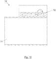
- Penning ion sources are used as an internal source for cyclotrons, such as for example the one represented in Figure 1 (longitudinal cross-sectional front view) and in Figure 2 (longitudinal cross-sectional perspective view), which corresponds to a double-cavity ion source.
- the double-cavity Penning ion source comprises two hollow bodies, each one made up of two parts, a conductive part (1, 1') and an insulating part (2, 2'), which fit together so that the interior walls thereof delimit a cylindrical cavity (3, 3').
- At least one of the conductive parts 1 has a gas supply inlet 4 through which a plasma-forming gas is introduced into the respective cavity 3 thereof.
- a coaxial conductor (5, 5') disposed in the cavity (3, 3') of the body (1, 1'), arranged parallel to the longitudinal axis of the cylindrical cavity (3, 3').
- Both cavities (3, 3') are interconnected by means of a common cylindrical expansion chamber (6) through respective holes (7, 7') made in the walls of the conductive parts (1, 1').
- a conductive element (9, 9') is introduced into each cavity (3, 3'), penetrating through the insulating part (2, 2'), and in electrical contact with the coaxial conductor (5, 5') of the cavity.
- the conductive element (9, 9') is excited with DC voltages of around 3000 V.
- To start the discharge it is necessary to open the gas flow and apply a potential difference of several thousand volts between anode and cathode (i.e., the conductive part 1/1' and the coaxial conductor 5/5').
- the power supply stabilises it by maintaining a potential difference between 500-1000V with a current of several hundred milliamps.
- the discharge that is established is of the DC type, requiring the emission of secondary electrons from the conductive material (such that they must be at a high temperature and be a material with high electron emissivity) and the ions that are expelled from the plasma are accelerated at high energy, causing erosion of the cathodes.
- Figure 3 shows a vertical cross section of an embodiment of the device object of the present invention, ion source 10, according to a cut plane perpendicular to the X-axis, wherein the external magnetic field B (normally generated by an electromagnet or a permanent magnet when the ion source is installed and running) is aligned with the vertical Z-axis of the reference system.
- the external magnetic field B normally generated by an electromagnet or a permanent magnet when the ion source is installed and running
- FIG. 4 shows a cross section of the ion source 10 according to the XY horizontal plane passing through the axis of the resonant cavity.
- the interior walls (11a, 11b, 11c) of a hollow body 11 are electrically conductive and define a cylindrical cavity 13.
- the entire body 11 is conductive, preferably made of copper.
- the body 11 has three interior walls: a first interior wall 11a, of circular geometry, a second interior wall 11b, also circular and opposite the first interior wall 11a, and a third interior wall 11c, of cylindrical geometry, which connects both circular interior walls (11a, 11b).
- a coaxial conductor 15 is disposed in the cavity 13 of the body 11, arranged parallel to the longitudinal axis of the cylindrical cavity 13. At least one of the ends (15a, 15b) of the coaxial conductor 15 is in contact with one of the circular interior walls (11a, 11b) of the body 11, forming a coaxial resonant cavity.
- the coaxial conductor 15 can short-circuit both interior walls (11a, 11b) to obtain a ⁇ /2 coaxial resonant cavity, obtaining the maximum electric field in the centre, or it short-circuits a single interior wall to obtain a ⁇ /4 coaxial resonant cavity (with the maximum electric field at the opposite end of the conductor).
- the body 11 has a gas supply port or inlet 14 (i.e., a hole or opening made in one of the walls thereof) through which a plasma-forming gas is introduced into the cavity 13.
- a gas supply port or inlet 14 i.e., a hole or opening made in one of the walls thereof
- Figure 4 shows a tube 20, hermetically coupled to the gas supply inlet 14, through which the gas is introduced into the cavity 13.
- the body 11 also has a power supply inlet 21 through which radio frequency energy is injected into the cavity 13.
- An expansion chamber 16 is connected to the cavity 13 through a plasma outlet hole 17 made in one of the walls of the body 11.
- An ion-extraction aperture 18 is disposed in one of the walls of the expansion chamber 16.
- the ion source 10 is introduced under vacuum into the chamber of a cyclotron, and the gas that is injected is partially transformed into plasma and the rest escapes through the ion-extraction aperture 18.
- the coaxial conductor 15 has a conductive protuberance 22 that extends radially into the cavity 13 with respect to the axis of the cylindrical cavity (i.e., perpendicular to said axis), said conductive protuberance 22 being opposite the plasma outlet hole 17 of the body 11 that connects the cavity 13 to the expansion chamber 16 (i.e., the conductive protuberance 22 is opposite the expansion chamber 16).
- the conductive protuberance 22 does not come into contact with the interior wall of the body 11, although it remains very close, usually less than 5 millimetres; this separation distance will largely depend on the dimensions of the resonant cavity.
- the ignition voltage, injected power in the case of RF will depend in turn on this separation distance and the density of the injected gas.
- the body 11 is short-circuited by the internal coaxial conductor 15 at one end 15a or at both ends (15a, 15b).
- the coaxial conductor 15 is an inner conductor that functions like an electrode opposite the outer conductor, the interior walls of the body 11, in such a way that when power is injected, the cavity 13 enters into resonance and the electric field that is established in the gap between the two conductors (11, 15) changes sign.
- a portion of the free end of the coaxial conductor 15, second end 15b is modified by means of a conductive protuberance or protrusion 22 directed towards the expansion chamber 16, in order to produce a concentration and an increase of the electric field in the area where the plasma is to be produced (plasma production area).
- the plasma produced escapes from the cavity 13 through the plasma outlet hole 17 towards the expansion chamber 16, forming a plasma column 23 aligned with the magnetic field B, from which the ions are extracted using the ion-extraction aperture 18.
- the expansion chamber 16 is a cavity, also preferably of cylindrical geometry, which performs the function of an expansion chamber for the plasma column 23.
- the expansion chamber 16 is a cylindrical cavity with a small radius so that after extracting the particles through the ion-extraction aperture 18 and accelerating them in the first turn, they do not collide with the source and are lost.
- the expansion chamber 16 also acts as a mechanical support, keeping the two symmetrical portions of the ion source separate, when they are a double-cavity ion source (as shown in Figures 1 and 2 ).
- a coaxial waveguide 24 which transports radio frequency/microwave energy is coupled through the power supply access, port or inlet 21, the coupling possibly being of the electrical (capacitive) or magnetic (inductive) type.
- Figure 4 shows a typical capacitive coupling, wherein the dielectric 25 that surrounds the inner conductor 26 of the coaxial waveguide 24 enables the hermetic sealing of the power supply inlet 21 (so that portion of the injected gas does not escapes through said inlet), and wherein the inner conductor 26 of the coaxial waveguide 24 protrudes from the dielectric 25, partially entering into the cavity 13.
- a typical inductive coupling uses a loop that short-circuits the interior of the coaxial waveguide with the resonant cavity.
- the frequency of the resonant cavity can be adjusted by means of an insert or moving part 27 that is partially introduced into the cavity 13.
- the moving part 27 can be displaced radially at the moment of the initial configuration of the ion source 10 (i.e., perpendicular to the axis of the cylindrical cavity 13), thus allowing the resonance frequency to be finely adjusted based on the volume of the movable part 27 that is introduced into the cavity 13.
- the moving part 27 is an optional element, not strictly necessary for the operation of the ion source, although it improves the operation by making it easier to adjust the resonance frequency.
- the moving part 27 can be made of conductive material (preferably copper) or of dielectric material (such as alumina), depending on the behaviour and the variation in frequency to be achieved.
- Figures 5 and 6 show two additional views of the ion source 10, according to one possible embodiment.
- Figure 5 illustrates a front view of the ion source 10, wherein the portion above the axis of the cavity 13 is shown in mid-section.
- Figure 6 shows a three-dimensional view of an ion source 10.
- the gas supply inlet 14 cannot be seen in Figure 6 as it is disposed at the rear of the body 11 in this view.
- the projection 70 shown in Figure 6 is an element with the same function as the movable part 27 of Figure 4 , an element by means of which the frequency of the resonant cavity is finely adjusted. In this case, the projection 70 is integrated into the body of the ion source, but it could be designed as a separate body.
- Figures 7 and 8 show, respectively and according to another embodiment, a front cross section and a perspective cross section of a double-cavity ion source 30, with a plane of symmetry 31 in the central portion of the ion-extraction aperture 18, both cavities (13, 13') being connected by a common expansion chamber 16, which allows the expansion of the plasma column 23 produced in each cavity (13, 13').
- the elements of the ion source 30 for each of the two cavities (13, 13') are the same as those shown in Figures 3 to 6 for the ion source 10 having a single cavity (first body 11 and second body 11', first coaxial conductor 15 and second coaxial conductor 15', first conductive protuberance 22 and second conductive protuberance 22', first plasma outlet hole 17 and second plasma outlet hole 17', etc.), with the particularity in this case that both cavities (13, 13') are opposite each other and share the expansion chamber 16.
- Double-cavity ion sources 30 are used to obtain plasma more easily and increase the production of particles, such that at both ends there are two plasma jets that converge at the height of the plane of symmetry 31, forming a single plasma column 23 in the central portion, wherein the ion-extraction aperture 18 is located to remove the desired particles, whether they are positive or negative ions.
- the length of the resonant cavity will be of the order of or less than ⁇ /2.
- the transverse dimensions, as well as those of the conductive protuberance 22 for concentrating the electric field, are determined by the specific parameters of the resonant cavity to be obtained, mainly the quality factor Q and characteristic impedance R/Q, and they will also have an effect on the resonant frequency of the cavity.
- the interior walls of the body 11 are made of a conductive material with low electrical resistivity and high thermal conductivity, generally copper or copper deposited on another metal, since there is a desire for the Q factor to be high and the power deposited on the walls to be rapidly dissipated.
- a generator which can be solid state, electron tube (magnetron, TWT, gyrotron, klystron, etc.) or a coil and capacitor resonant circuit, depending on the frequency, power and required working mode.
- Said power travels through a waveguide, generally coaxial or hollow (e.g., rectangular), to the cavity, wherein the power is transferred to the resonant cavity through a coupling (electrical, inductive or through-hole), minimising reflections and power losses.
- the value of the electric field increases in magnitude in such a way that it reaches a point when the plasma ignites (Paschen curve for oscillating electromagnetic fields).
- the resonant frequency of the cavity shifts, such that if the frequency of the electromagnetic field supplied to the cavity remains constant, power begins to be reflected due to the difference in impedances, reaching a point when all the power except that which is necessary to maintain the discharge and compensate for losses in the walls of the cavity will be reflected, stabilising the system in the steady state.
- a specific design of the present invention uses a ⁇ /4 coaxial resonant cavity, approximately 3 cm long for a frequency of 2.45 GHz, with one end short-circuited and the other open, and made of copper.
- a conductive protuberance 22 protruding in the same direction as the magnetic field (in the vertical direction Z) which is opposite the plasma outlet hole 17 and which allows increasing the electric field in that area to achieve plasma formation with less power.
- the plasma leaves through the plasma outlet hole 17 and enters the expansion chamber 16, where it spreads mainly in the direction of the magnetic field lines (parallel to the Z-axis) forming a plasma column 23, and passes close to the ion-extraction aperture 18, wherein the ions are extracted by means of an electric field.
- the gas supply inlet 14 is implemented by means of a simple hole connected to a tube 20, while the coupling of the radio frequency system is carried out with electrical coupling by means of a protruding cylinder (dielectric 25) connected to the inner conductor 26 of a coaxial waveguide 24.
- a protruding cylinder dielectric 25
- Other alternatives for introducing power are a magnetic coupling through a loop or a hole made in a waveguide.
- the resonant frequency of the cavity is adjusted by the moving part 27.
- Figure 9 illustrates an ion source 40 according to another possible embodiment, wherein the location of the plasma outlet hole 17 (in this case it is located in the circular second interior wall 11b) and the orientation of the expansion chamber 16 changes with respect to the cavity 13. Furthermore, the conductive protuberance 22 of the ion source 40 for this embodiment preferably has a circular cross section, to thereby maintain internal symmetry in the cavity 13 (the conductive protuberance 22 of Figure 9 protrudes on each side, top and bottom, of the coaxial conductor 15).
- the conductive protuberance 22 of Figure 3 can have different types of cross sections, depending on the geometry and dimensions of the cavity, the coaxial conductor and the plasma outlet hole (the cross section can be optimised by means of simulation to obtain a greater concentration of the electric field opposite of the plasma outlet hole 17 that favours the formation and stability of the plasma), so that the conductive protuberance 22 only protrudes on one side, at the top.
- the upper circle illustrated in Figure 9 represents the resonator 12 (i.e., the coaxial resonant cavity) that forms when ion source 40 is in operation.
- FIGS 10 and 11 show, respectively, a front and perspective view (partially sectioned) of a cyclotron 41 (in the figure of the cyclotron, components such as the magnet coils, the radio frequency-acceleration system, the extraction system and the vacuum and opening system of the iron have been omitted) with axial configuration for introducing an ion source.
- the ion source is introduced with the axial configuration of Figure 9 , wherein the electromagnetic and mechanical design of the ion sources is simpler.
- Figures 12 and 13 show a cyclotron 46 with radial configuration for introducing the ion source, wherein the design of the ion sources is more complicated (it corresponds to the ion sources represented in Figures 3 to 6 ).
- Figures 10 , 11 , 12 and 13 the following references are used:
- a coaxial waveguide 24 which transports radio frequency/microwave energy is coupled through the power supply input 21.
- the coupling can be electrical/capacitive or magnetic/inductive.
- Figure 14 shows an embodiment like the one shown in Figure 6 but replacing the capacitive coupling with a magnetic coupling, wherein a loop 49 short-circuits the inner conductor 26 of the coaxial waveguide 24 with the interior wall of the body 11.
- Figures 15 and 16 show another type of coupling, coupling by rectangular waveguide 71, in two different views (top view and perspective view, with a partial cross section). In this case, the coupling is performed by means of a hole 72 that joins the cavity 13 to the vacuum of the rectangular waveguide 71.
- the ion source 10 has larger dimensions due to the rectangular waveguide 71, which must also be under vacuum.
- Figures 17, 18 , 19 and 20 show different views in partial section (in particular, a front view, a top view, a front perspective view and a rear perspective view, respectively) of an embodiment of the ion source 10 wherein the two ends (15a, 15b) of the coaxial conductor 15 are respectively in contact with the two circular interior walls (11a, 11b) of the body 11, thus obtaining a ⁇ /2 coaxial resonant chamber.
- FIG 21 shows, by way of example, a complete radio frequency system 50 in which the ion source (10; 30; 40) of the present invention can be used.
- the radio frequency system comprises a generator 51 of sufficient power and adjustable parameters to achieve the ignition of the plasma, a circulator 52 with a load 53 to absorb the reflected power and a directional coupler 54 with a power meter 55 to monitor the incident and reflected power.
- the ion source (10; 30; 40) is placed immersed in a magnetic field generated by an electromagnet or by a permanent magnet 56, wherein the direction of the field lines is not important, only their movement.
- the ion source (10; 30; 40) is joined through the gas supply inlet 14 to a gas injection system 57, which comprises a gas reservoir or tank 58 and is dosed by means of a regulation system 59.
- the ion source (10; 30; 40) is disposed in a chamber 60 with sufficient vacuum so that the ions are not neutralised by the residual gas and can be accelerated for later use.
- the necessary radio frequency power is provided by the generator 51, and the transmitted power is measured with the power meter 55 connected to the directional coupler 54.
- the generator 51 is protected with the circulator 52 which diverts the power reflected by the ion source (10; 30; 40) to the load 53.
Abstract
- A hollow body (11) with conductive interior walls that define a cylindrical cavity (13), with a gas supply inlet (14) for plasma-forming gases and a power supply inlet (21) for injecting radio frequency energy into the cavity (13).
- An expansion chamber (16) connected to the cavity (13) by means of a plasma outlet hole (17).
- An ion-extraction aperture (18) in contact with the expansion chamber (16).
- A coaxial conductor (15) disposed in the cavity (13), parallel to the longitudinal axis thereof, one or both ends of the coaxial conductor (15) being in contact with a circular interior wall of the body (11), forming a coaxial resonant cavity; the coaxial conductor (15) having a conductive protuberance (22) opposite the plasma outlet hole (17) and which extends radially into the cavity (13).
Description
- The present invention falls within the field of ion sources for particle accelerators.
- An ion source is the component of particle accelerators where the gas is ionised, transforming into plasma, and from which the charged particles are then extracted to be accelerated. Ion sources are mainly used as internal sources in cyclotrons to produce lightweight positive ions and negative hydrogen. These types of machines have been traditionally used in the world of research as multipurpose beam machines for use in multiple fields. They have recently been used for radioisotope synthesis in radiopharmaceutical applications, as well as in proton/hadron therapy machines for the treatment of tumours.
- Ion sources have traditionally been very present in the world of research in different fields, including their use in particle accelerators, and in the study of materials or the structure of matter. To generate ions, one starts with the material to be ionised (generally a gas) and electrons are removed or added to the atoms by means of one or more of the following processes: electron impact (direct ionisation and/or charge exchange), photoionisation and surface ionisation.
- In its simplest scheme, an ion source is made up of a main chamber where the process takes place, material to ionise (introduced previously or continuously), an energy source for ionisation and an extraction system. According to the process followed, a general classification of the different types of ion sources can be made:
- Electron bombardment: they use accelerated electrons, typically generated in a cathode at a certain temperature, which impact the material and ionise the atoms and/or molecules thereof.
- DC/pulsed plasma discharge: they are similar to the previous sources in that they use a beam of electrons generated by a cathode, but in this case the pressures at which they operate are higher. For this reason, a plasma is generated which the fast electrons are responsible for maintaining by depositing energy in the form of collisions. This category includes Plasmatron, Duoplasmatron, Magnetron and Penning sources. They generally use magnetic fields to confine the paths of fast electrons and increase ionisation. The drawback of these sources is erosion on the cathode due to the high potential difference of the cathode, necessary for accelerating the electrons, which causes the ions to be accelerated in the opposite direction and impact against the cathode, removing material (sputtering) and limiting the life of said cathode.
- Radio-frequency discharge: they are an evolution of DC sources because they use an alternating electric field to accelerate the electrons instead of a continuous one. There are two types of these sources depending on how the plasma and the electric field are generated: capacitively coupled plasma (CCP) discharges and inductively coupled plasma (ICP) discharges. At low frequencies they continue to produce sputtering on the "cathodes" due to a high potential between the plasma and the metal medium; however, at high frequencies this potential decreases below a certain threshold and sputtering is practically non-existent, significantly increasing the life of said "cathodes".
- Electron Cyclotron Resonance (ECR/ECRIS): a particular design of radio-frequency discharge, since it is based on exciting the cyclotron resonance of electrons located in a magnetic field with a wave with suitable circular polarisation, which causes highly efficient absorption of the electromagnetic field energy in resonance areas which results in high ionisation.
- Laser: the method used in laser ion sources is photoionisation by means of several high-power lasers, the wavelength of which is tuned to different electronic transitions, achieving successive excitation of the electrons of the atom to be ionised.
- Surface ionisation: the method for producing ions involves heating a high work function material and injecting the material to be ionised.
- Charge exchange: this type of source uses a metal vapour with a high electron transfer rate through which it passes ions of the desired atom so that it becomes negatively charged.
- In the case of internal ion sources for cyclotrons, the preferred application field for the present invention, due to the internal configuration of cyclotrons, with very little space available for internally coupling the ion sources and a very high magnetic field in the vertical direction which traps the paths of the electrons and does not let them move freely, the only internal sources that have been used to date for cyclotrons are Penning sources. Penning ion sources have two cathodes placed at the vertical ends and a hollow tube parallel to the magnetic field that surrounds them. Said cathodes can be externally heated or remain initially cool and then heated with ion bombardment from the discharge. Due to the symmetrical configuration of the cathodes and the magnetic field, the electrons are emitted and accelerated, moving in helical paths that increase ionisation, and when reaching the opposite end they are reflected due to the electric field. The collisions of fast electrons with the injected gas results in the creation of a plasma from which both positive ions and negative ions can be extracted. Penning ion sources have the drawback of the sputtering of cathodes which, despite being commonly made of materials with high resistance and high electron emission (such as tantalum), are subjected to excessive wear that makes frequent replacement necessary.
- Penning ion sources are very simple and compact, using DC discharge. The use of an external source adds greater complexity to the system although it allows other methods to be used to generate the plasma, such that manufacturers do not usually include them in their commercial cyclotrons. The problem with all sources that use DC discharges is that this type of discharge erodes the cathodes while the plasma is active, meaning that they must be changed periodically and in these machines that are used for medical applications, it is generally desirable to have it running for as long as possible without interruptions. Furthermore, in the case of producing H-, the high-energy electrons from the DC discharge are the particles that contribute the most to the destruction of H-, so that the drawn current is reduced.
- Therefore, it is necessary to have an internal ion source for cyclotrons that solves these drawbacks.
- The present invention relates to a low-erosion radio frequency ion source, especially useful for use as an internal ion source for cyclotrons.
- The ion source comprises:
- A hollow body whose interior walls define a cylindrical cavity. The body has a gas supply inlet through which a plasma-forming gas is introduced into the cavity. The body has a power supply inlet through which radio frequency energy is injected into the cavity. The interior walls of the body are electrically conductive (preferably the entire body is conductive).
- An expansion chamber connected to the cavity through a plasma outlet hole made in the body.
- An ion-extraction aperture in contact with the expansion chamber.
- A coaxial conductor disposed in the cavity of the body, arranged parallel to the longitudinal axis of the cavity. At least one of the ends of the coaxial conductor is in contact with at least one circular interior wall of the body, forming a coaxial resonant cavity. The coaxial conductor has a conductive protuberance that extends radially into the cavity. The conductive protuberance is opposite the plasma outlet hole.
- In one embodiment, the ion source comprises a movable part partially introduced radially into the cavity through an opening made in the body to finely adjust the frequency of the resonant cavity. The moving part is preferably made of conductive material or dielectric material.
- The radio-frequency energy supply is provided through a capacitive coupling or inductive coupling. Capacitive coupling is performed by means of a coaxial waveguide whose inner conductor is partially introduced into the cavity through the power supply input. Inductive coupling is performed by means of a loop that short-circuits an interior wall of the body with an inner conductor of a coaxial waveguide introduced through the power supply input.
- In one embodiment, a first end of the coaxial conductor is in contact with a circular interior wall of the body, the second end of the coaxial conductor being free. In this embodiment, the conductive protuberance is preferably disposed at the second end of the coaxial conductor. The expansion chamber is preferably cylindrical and is arranged so that the longitudinal axis thereof is perpendicular to the longitudinal axis of the cavity. Alternatively, the expansion chamber can be arranged so that the longitudinal axis thereof is parallel to the longitudinal axis of the cavity.
- In another embodiment, the two ends of the coaxial conductor are respectively in contact with the two circular interior walls of the body. In this embodiment, the conductive protuberance is preferably disposed in the central portion of the coaxial conductor.
- The ion source can have a double cavity, comprising a second body and a second conductor that form a second coaxial resonant cavity. The cavities of both bodies are connected to each other through a common expansion chamber.
- The ion source of the present invention enables solving the drawbacks of the Penning internal ion sources used in cyclotrons, in which the plasma is generated causing erosion on the conductive materials. Erosion occurs because the plasma is positively charged, so the electrons are attracted to the plasma, while the positive ions are rejected and accelerated by the potential difference between the plasma and the wall. Thus, if the energy of the ions at the time of collision with the wall is high enough (>> 1 eV), atoms are removed from the material when the ion collides with the conductive material. The number of atoms removed depends on the conductive material.
- In the proposed ion source, the plasma is generated without producing erosion on the conductive materials (i.e., the electrodes) used in the ion source, such that the maintenance and interruptions produced when the source is operating are much less than in the case of a Penning source. Thus, in an embodiment of the present invention where the radio frequency energy supply is used by means of capacitive discharge, working at a sufficiently high frequency (for example, 2.45 GHz), no erosion occurs on the source materials. Plasma discharge can operate in two different modes: the alpha mode, where the discharge is maintained thanks to the secondary electrons emitted by the cathode (or the portion that functioned as the cathode at that time), and the gamma mode, where the mechanism for heating the plasma is collisionless heating. The alpha mode occurs in DC discharges and in RF at low frequencies, and the transition to the gamma mode occurs starting at a certain frequency that depends on the characteristics of the plasma.
- The formation of a resonator or coaxial resonant chamber makes it possible to increase the electric field and facilitate ignition, so that the ion source of the present invention further achieves much lower energy consumption.
- In the ion source of the present invention, it is also not necessary to have hot cathodes at temperatures of the order of 2000 K; therefore, instead of using conductive materials with high resistance and high electron emission, such as tantalum, other less expensive materials such as copper can be used. Due to the collision of the ions with the cathodes, the kinetic energy thereof is converted into thermal energy which increases the temperature of the cathodes, which emit electrons by thermionic effect, which are necessary to maintain the DC discharge in Penning sources. As in the present invention, collisions with cathodes are much less energetic, the heating of the cathodes is much lower, and less thermally restrictive conductive materials can be used (i.e., with lower melting temperature and higher conductivity), such as copper.
- Furthermore, in the case of producing H-, since the present ion source does not generate high-energy electrons in the plasma, the drawn current is significantly increased. The cross section for producing H- is the highest at low energy (1-10 eV); at higher energies the cross section for production decreases significantly, while the cross section for producing the destruction of H-increases notably, as explained in detail in H. Tawara, "Cross Sections and Related Data for Electron Collisions with Hydrogen Molecules and Molecular Ions".
- What follows is a very brief description of a series of drawings that aid in better understanding the invention, and which are expressly related to an embodiment of said invention that is presented by way of a non-limiting example of the same.
-
Figure 1 shows, according to the state of the art, a front view of a longitudinal cross section of a double-cavity Penning ion source. -
Figure 2 shows, according to the state of the art, a perspective view of a longitudinal cross section of a double-cavity Penning ion source. -
Figures 3 ,4 ,5 and6 show different cross-sectional views of an ion source according to a possible embodiment of the present invention. -
Figures 7 and8 show cross-sectional views of a double-cavity ion source according to a possible embodiment of the present invention. -
Figure 9 represents another possible embodiment of an ion source, especially suitable for cyclotrons with an axial configuration. -
Figures 10 and11 show a cyclotron with an axial configuration for introducing the ion source. -
Figures 12 and13 show a cyclotron with a radial configuration for introducing the ion source. -
Figure 14 shows an embodiment of the ion source similar to that shown inFigure 6 but replacing the capacitive coupling with an inductive coupling. -
Figures 15 and16 show an embodiment of the ion source with a different type of coupling (rectangular waveguide coupling). -
Figures 17, 18 ,19 and 20 show different partial cross-sectional views of an ion source according to another possible embodiment. -
Figure 21 illustrates, by way of example, a complete radio frequency system in which the ion source of the present invention can be used. - The present invention relates to an ion source designed mainly for use as an internal source in cyclotrons.
- Currently, Penning ion sources are used as an internal source for cyclotrons, such as for example the one represented in
Figure 1 (longitudinal cross-sectional front view) and inFigure 2 (longitudinal cross-sectional perspective view), which corresponds to a double-cavity ion source. - The double-cavity Penning ion source comprises two hollow bodies, each one made up of two parts, a conductive part (1, 1') and an insulating part (2, 2'), which fit together so that the interior walls thereof delimit a cylindrical cavity (3, 3'). At least one of the
conductive parts 1 has agas supply inlet 4 through which a plasma-forming gas is introduced into therespective cavity 3 thereof. In each cavity (3, 3') there is a coaxial conductor (5, 5') disposed in the cavity (3, 3') of the body (1, 1'), arranged parallel to the longitudinal axis of the cylindrical cavity (3, 3'). - Both cavities (3, 3') are interconnected by means of a common cylindrical expansion chamber (6) through respective holes (7, 7') made in the walls of the conductive parts (1, 1'). An ion-extraction aperture (8) disposed in the walls which delimit the expansion chamber (6), in the central portion thereof, makes it possible to extract ions from the plasma generated from the gas introduced into the cavities (3, 3').
- A conductive element (9, 9') is introduced into each cavity (3, 3'), penetrating through the insulating part (2, 2'), and in electrical contact with the coaxial conductor (5, 5') of the cavity. The conductive element (9, 9') is excited with DC voltages of around 3000 V. To start the discharge, it is necessary to open the gas flow and apply a potential difference of several thousand volts between anode and cathode (i.e., the
conductive part 1/1' and thecoaxial conductor 5/5'). After igniting the plasma, the power supply stabilises it by maintaining a potential difference between 500-1000V with a current of several hundred milliamps. The discharge that is established is of the DC type, requiring the emission of secondary electrons from the conductive material (such that they must be at a high temperature and be a material with high electron emissivity) and the ions that are expelled from the plasma are accelerated at high energy, causing erosion of the cathodes. -
Figure 3 shows a vertical cross section of an embodiment of the device object of the present invention,ion source 10, according to a cut plane perpendicular to the X-axis, wherein the external magnetic field B (normally generated by an electromagnet or a permanent magnet when the ion source is installed and running) is aligned with the vertical Z-axis of the reference system. - The operation of the
ion source 10 is based on a coaxial resonant cavity.Figure 4 shows a cross section of theion source 10 according to the XY horizontal plane passing through the axis of the resonant cavity. The interior walls (11a, 11b, 11c) of ahollow body 11 are electrically conductive and define acylindrical cavity 13. In one embodiment, theentire body 11 is conductive, preferably made of copper. - The
body 11 has three interior walls: a firstinterior wall 11a, of circular geometry, a secondinterior wall 11b, also circular and opposite the firstinterior wall 11a, and a thirdinterior wall 11c, of cylindrical geometry, which connects both circular interior walls (11a, 11b). - A
coaxial conductor 15 is disposed in thecavity 13 of thebody 11, arranged parallel to the longitudinal axis of thecylindrical cavity 13. At least one of the ends (15a, 15b) of thecoaxial conductor 15 is in contact with one of the circular interior walls (11a, 11b) of thebody 11, forming a coaxial resonant cavity. In this way, thecoaxial conductor 15 can short-circuit both interior walls (11a, 11b) to obtain a λ/2 coaxial resonant cavity, obtaining the maximum electric field in the centre, or it short-circuits a single interior wall to obtain a λ/4 coaxial resonant cavity (with the maximum electric field at the opposite end of the conductor). In the example ofFigures 3 and4 , only one of the ends of thecoaxial conductor 15, specifically thefirst end 15a, short-circuits one of the circular interior walls of the body 11 (in particular, the firstinterior wall 11a), thebody 11 and thecoaxial conductor 15 thus forming a λ/4 coaxial resonant cavity, with the maximum electric field at thesecond end 15b of thecoaxial conductor 15. - The
body 11 has a gas supply port or inlet 14 (i.e., a hole or opening made in one of the walls thereof) through which a plasma-forming gas is introduced into thecavity 13.Figure 4 shows atube 20, hermetically coupled to thegas supply inlet 14, through which the gas is introduced into thecavity 13. These types of ion sources generally work with Hydrogen, and to a lesser extent Deuterium and Helium, depending on the ion to be extracted. - The
body 11 also has apower supply inlet 21 through which radio frequency energy is injected into thecavity 13. - An
expansion chamber 16 is connected to thecavity 13 through aplasma outlet hole 17 made in one of the walls of thebody 11. An ion-extraction aperture 18 is disposed in one of the walls of theexpansion chamber 16. Theion source 10 is introduced under vacuum into the chamber of a cyclotron, and the gas that is injected is partially transformed into plasma and the rest escapes through the ion-extraction aperture 18. - The
coaxial conductor 15 has aconductive protuberance 22 that extends radially into thecavity 13 with respect to the axis of the cylindrical cavity (i.e., perpendicular to said axis), saidconductive protuberance 22 being opposite theplasma outlet hole 17 of thebody 11 that connects thecavity 13 to the expansion chamber 16 (i.e., theconductive protuberance 22 is opposite the expansion chamber 16). Theconductive protuberance 22 does not come into contact with the interior wall of thebody 11, although it remains very close, usually less than 5 millimetres; this separation distance will largely depend on the dimensions of the resonant cavity. The ignition voltage, injected power in the case of RF, will depend in turn on this separation distance and the density of the injected gas. - Depending on where the plasma is to be generated, the
body 11 is short-circuited by the internalcoaxial conductor 15 at oneend 15a or at both ends (15a, 15b). Thecoaxial conductor 15 is an inner conductor that functions like an electrode opposite the outer conductor, the interior walls of thebody 11, in such a way that when power is injected, thecavity 13 enters into resonance and the electric field that is established in the gap between the two conductors (11, 15) changes sign. - In the example of
Figures 3 and4 , a portion of the free end of thecoaxial conductor 15,second end 15b, is modified by means of a conductive protuberance orprotrusion 22 directed towards theexpansion chamber 16, in order to produce a concentration and an increase of the electric field in the area where the plasma is to be produced (plasma production area). The plasma produced escapes from thecavity 13 through theplasma outlet hole 17 towards theexpansion chamber 16, forming aplasma column 23 aligned with the magnetic field B, from which the ions are extracted using the ion-extraction aperture 18. Theexpansion chamber 16 is a cavity, also preferably of cylindrical geometry, which performs the function of an expansion chamber for theplasma column 23. In the ion sources applied to cyclotrons, theexpansion chamber 16 is a cylindrical cavity with a small radius so that after extracting the particles through the ion-extraction aperture 18 and accelerating them in the first turn, they do not collide with the source and are lost. Theexpansion chamber 16 also acts as a mechanical support, keeping the two symmetrical portions of the ion source separate, when they are a double-cavity ion source (as shown inFigures 1 and2 ). - As shown in the embodiment of
Figure 4 , acoaxial waveguide 24 which transports radio frequency/microwave energy is coupled through the power supply access, port orinlet 21, the coupling possibly being of the electrical (capacitive) or magnetic (inductive) type.Figure 4 shows a typical capacitive coupling, wherein the dielectric 25 that surrounds theinner conductor 26 of thecoaxial waveguide 24 enables the hermetic sealing of the power supply inlet 21 (so that portion of the injected gas does not escapes through said inlet), and wherein theinner conductor 26 of thecoaxial waveguide 24 protrudes from the dielectric 25, partially entering into thecavity 13. Unlike this capacitive coupling, a typical inductive coupling uses a loop that short-circuits the interior of the coaxial waveguide with the resonant cavity. - The frequency of the resonant cavity can be adjusted by means of an insert or moving
part 27 that is partially introduced into thecavity 13. The movingpart 27 can be displaced radially at the moment of the initial configuration of the ion source 10 (i.e., perpendicular to the axis of the cylindrical cavity 13), thus allowing the resonance frequency to be finely adjusted based on the volume of themovable part 27 that is introduced into thecavity 13. The movingpart 27 is an optional element, not strictly necessary for the operation of the ion source, although it improves the operation by making it easier to adjust the resonance frequency. The movingpart 27 can be made of conductive material (preferably copper) or of dielectric material (such as alumina), depending on the behaviour and the variation in frequency to be achieved. -
Figures 5 and6 show two additional views of theion source 10, according to one possible embodiment.Figure 5 illustrates a front view of theion source 10, wherein the portion above the axis of thecavity 13 is shown in mid-section.Figure 6 shows a three-dimensional view of anion source 10. Thegas supply inlet 14 cannot be seen inFigure 6 as it is disposed at the rear of thebody 11 in this view. Theprojection 70 shown inFigure 6 is an element with the same function as themovable part 27 ofFigure 4 , an element by means of which the frequency of the resonant cavity is finely adjusted. In this case, theprojection 70 is integrated into the body of the ion source, but it could be designed as a separate body. -
Figures 7 and8 show, respectively and according to another embodiment, a front cross section and a perspective cross section of a double-cavity ion source 30, with a plane ofsymmetry 31 in the central portion of the ion-extraction aperture 18, both cavities (13, 13') being connected by acommon expansion chamber 16, which allows the expansion of theplasma column 23 produced in each cavity (13, 13'). The elements of theion source 30 for each of the two cavities (13, 13') are the same as those shown inFigures 3 to 6 for theion source 10 having a single cavity (first body 11 and second body 11', firstcoaxial conductor 15 and second coaxial conductor 15', firstconductive protuberance 22 and second conductive protuberance 22', firstplasma outlet hole 17 and second plasma outlet hole 17', etc.), with the particularity in this case that both cavities (13, 13') are opposite each other and share theexpansion chamber 16. Double-cavity ion sources 30 are used to obtain plasma more easily and increase the production of particles, such that at both ends there are two plasma jets that converge at the height of the plane ofsymmetry 31, forming asingle plasma column 23 in the central portion, wherein the ion-extraction aperture 18 is located to remove the desired particles, whether they are positive or negative ions. - The length of the resonant cavity (along the Y-axis) is of the order of or less than λ/4 (where λ is the wavelength associated with the oscillating electromagnetic field given by the ratio λ = flc, where f is the oscillation frequency and c speed of light) in the case of resonant cavities short-circuited at one end (quarter-wave cavities). In the case of half-wave resonant cavities, short-circuited at both ends and with plasma formation in the central portion of the inner conductor, the length of the resonant cavity will be of the order of or less than λ/2. The transverse dimensions, as well as those of the
conductive protuberance 22 for concentrating the electric field, are determined by the specific parameters of the resonant cavity to be obtained, mainly the quality factor Q and characteristic impedance R/Q, and they will also have an effect on the resonant frequency of the cavity. - The interior walls of the
body 11 are made of a conductive material with low electrical resistivity and high thermal conductivity, generally copper or copper deposited on another metal, since there is a desire for the Q factor to be high and the power deposited on the walls to be rapidly dissipated. - To operate the ion source (10; 30), one starts from the initial state, where there is no energy in the
cavity 13 or cavities (13, 13'). The radio frequency energy that is introduced into the cavity is produced in a generator, which can be solid state, electron tube (magnetron, TWT, gyrotron, klystron, etc.) or a coil and capacitor resonant circuit, depending on the frequency, power and required working mode. Said power travels through a waveguide, generally coaxial or hollow (e.g., rectangular), to the cavity, wherein the power is transferred to the resonant cavity through a coupling (electrical, inductive or through-hole), minimising reflections and power losses. As electromagnetic energy is introduced into the cavity (with a frequency equal to the resonant frequency of the cavity), the value of the electric field increases in magnitude in such a way that it reaches a point when the plasma ignites (Paschen curve for oscillating electromagnetic fields). Once the plasma is formed, which expands through theplasma outlet hole 17 spreading along the magnetic field lines generated by an electromagnet or a permanent magnet, the resonant frequency of the cavity shifts, such that if the frequency of the electromagnetic field supplied to the cavity remains constant, power begins to be reflected due to the difference in impedances, reaching a point when all the power except that which is necessary to maintain the discharge and compensate for losses in the walls of the cavity will be reflected, stabilising the system in the steady state. - According to a possible embodiment, a specific design of the present invention uses a λ/4 coaxial resonant cavity, approximately 3 cm long for a frequency of 2.45 GHz, with one end short-circuited and the other open, and made of copper. In the portion of the open end of the inner
coaxial conductor 15 there is aconductive protuberance 22 protruding in the same direction as the magnetic field (in the vertical direction Z) which is opposite theplasma outlet hole 17 and which allows increasing the electric field in that area to achieve plasma formation with less power. The plasma leaves through theplasma outlet hole 17 and enters theexpansion chamber 16, where it spreads mainly in the direction of the magnetic field lines (parallel to the Z-axis) forming aplasma column 23, and passes close to the ion-extraction aperture 18, wherein the ions are extracted by means of an electric field. - In the embodiment shown in the figures, the
gas supply inlet 14 is implemented by means of a simple hole connected to atube 20, while the coupling of the radio frequency system is carried out with electrical coupling by means of a protruding cylinder (dielectric 25) connected to theinner conductor 26 of acoaxial waveguide 24. Other alternatives for introducing power are a magnetic coupling through a loop or a hole made in a waveguide. The resonant frequency of the cavity is adjusted by the movingpart 27. -
Figure 9 illustrates anion source 40 according to another possible embodiment, wherein the location of the plasma outlet hole 17 (in this case it is located in the circular secondinterior wall 11b) and the orientation of theexpansion chamber 16 changes with respect to thecavity 13. Furthermore, theconductive protuberance 22 of theion source 40 for this embodiment preferably has a circular cross section, to thereby maintain internal symmetry in the cavity 13 (theconductive protuberance 22 ofFigure 9 protrudes on each side, top and bottom, of the coaxial conductor 15). However, theconductive protuberance 22 ofFigure 3 can have different types of cross sections, depending on the geometry and dimensions of the cavity, the coaxial conductor and the plasma outlet hole (the cross section can be optimised by means of simulation to obtain a greater concentration of the electric field opposite of theplasma outlet hole 17 that favours the formation and stability of the plasma), so that theconductive protuberance 22 only protrudes on one side, at the top. The upper circle illustrated inFigure 9 represents the resonator 12 (i.e., the coaxial resonant cavity) that forms whenion source 40 is in operation. - While in the
ion source 10 ofFigures 3 to 6 the main axis of theexpansion chamber 16 is disposed perpendicular to the axis of thecylindrical cavity 13, in theion source 40 ofFigure 9 both axes are parallel (in the example ofFigure 9 they coincide), which allows the ion sources to be axially coupled in cyclotrons. - Internal ion sources for cyclotrons can be radially or axially introduced into the cyclotron.
Figures 10 and11 show, respectively, a front and perspective view (partially sectioned) of a cyclotron 41 (in the figure of the cyclotron, components such as the magnet coils, the radio frequency-acceleration system, the extraction system and the vacuum and opening system of the iron have been omitted) with axial configuration for introducing an ion source. In thecyclotron 41 ofFigures 10 and11 , the ion source is introduced with the axial configuration ofFigure 9 , wherein the electromagnetic and mechanical design of the ion sources is simpler.Figures 12 and13 show acyclotron 46 with radial configuration for introducing the ion source, wherein the design of the ion sources is more complicated (it corresponds to the ion sources represented inFigures 3 to 6 ). InFigures 10 ,11 ,12 and13 , the following references are used: - 41 and 46 - Cyclotron.
- 42 and 47 - Ion source flange. It has gas bushings, the waveguide and liquid cooling (if necessary). It also creates the vacuum seal.
- 43 - Gas tube, waveguide and cooling. They act as a mechanical support for the ion source and can be integrated or stand alone. It could include a dedicated stand if necessary. In the case of radial insertion, they are usually shielded to withstand the impact of the particles that are lost.
- 44 - Magnet iron. It guides the magnetic field and is used to attenuate radiation.
- 45 - Magnet pole (the circular portion can be machined to modify the magnetic field).
- 48 - Ion source.
- As indicated above in the description of
Figure 4 , acoaxial waveguide 24 which transports radio frequency/microwave energy is coupled through thepower supply input 21. The coupling can be electrical/capacitive or magnetic/inductive.Figure 14 shows an embodiment like the one shown inFigure 6 but replacing the capacitive coupling with a magnetic coupling, wherein aloop 49 short-circuits theinner conductor 26 of thecoaxial waveguide 24 with the interior wall of thebody 11.Figures 15 and16 show another type of coupling, coupling byrectangular waveguide 71, in two different views (top view and perspective view, with a partial cross section). In this case, the coupling is performed by means of ahole 72 that joins thecavity 13 to the vacuum of therectangular waveguide 71. It would act as an electric dipole and a magnetic dipole that radiate on both sides, such that if there is higher energy density on one side, energy is transferred to the other side until they reach equilibrium. In this embodiment, theion source 10 has larger dimensions due to therectangular waveguide 71, which must also be under vacuum. -
Figures 17, 18 ,19 and 20 show different views in partial section (in particular, a front view, a top view, a front perspective view and a rear perspective view, respectively) of an embodiment of theion source 10 wherein the two ends (15a, 15b) of thecoaxial conductor 15 are respectively in contact with the two circular interior walls (11a, 11b) of thebody 11, thus obtaining a λ/2 coaxial resonant chamber. -
Figure 21 shows, by way of example, a completeradio frequency system 50 in which the ion source (10; 30; 40) of the present invention can be used. The radio frequency system comprises agenerator 51 of sufficient power and adjustable parameters to achieve the ignition of the plasma, acirculator 52 with aload 53 to absorb the reflected power and adirectional coupler 54 with apower meter 55 to monitor the incident and reflected power. - The ion source (10; 30; 40) is placed immersed in a magnetic field generated by an electromagnet or by a
permanent magnet 56, wherein the direction of the field lines is not important, only their movement. The ion source (10; 30; 40) is joined through thegas supply inlet 14 to agas injection system 57, which comprises a gas reservoir ortank 58 and is dosed by means of aregulation system 59. The ion source (10; 30; 40) is disposed in achamber 60 with sufficient vacuum so that the ions are not neutralised by the residual gas and can be accelerated for later use. - The necessary radio frequency power is provided by the
generator 51, and the transmitted power is measured with thepower meter 55 connected to thedirectional coupler 54. Thegenerator 51 is protected with thecirculator 52 which diverts the power reflected by the ion source (10; 30; 40) to theload 53.
Claims (13)
- A low-erosion internal ion source for cyclotrons, comprising:a hollow body (11) whose interior walls (11a, 11b, 11c) define a cylindrical cavity (13), wherein the body (11) has a gas supply inlet (14) through which a plasma-forming gas is introduced into the cavity (13);a coaxial conductor (15) disposed in the cavity (13) of the body (11) and arranged parallel to the longitudinal axis of the cavity (13);an expansion chamber (16) connected to the cavity (13) through a plasma outlet hole (17) made in the body (11);an ion-extraction aperture (18) in contact with the expansion chamber (16);characterised in that:the body (11) has a power supply input (21) through which radio frequency energy is injected into the cavity (13);the interior walls of the body (11) are conductive;at least one of the ends (15a; 15b) of the coaxial conductor (15) is in contact with at least one circular interior wall (11a, 11b) of the body (11), forming a coaxial resonant cavity;the coaxial conductor (15) has a conductive protuberance (22) that extends radially into the cavity (13), said conductive protuberance (22) being opposite the plasma outlet hole (17).
- The ion source according to claim 1, characterised in that it comprises a movable part (27) partially introduced radially into the cavity (13) through an opening made in the body (11) to finely adjust the frequency of the resonant cavity.
- The ion source according to claim 2, characterised in that the moving part (27) is made of conductive material.
- The ion source according to claim 2, characterised in that the moving part (27) is made of dielectric material.
- The ion source according to any of claims 1 to 4, characterised in that the radio frequency energy supply is provided through a capacitive coupling by means of a coaxial waveguide (24) whose inner conductor (26) is partially introduced into the cavity (13) through the power supply input (21).
- The ion source according to any of claims 1 to 4, characterised in that the radio frequency energy supply is provided through an inductive coupling by means of a loop (49) that short-circuits an interior wall of the body (11) with an inner conductor (26) of a coaxial waveguide (24) introduced through the power supply input (21).
- The ion source according to any of claims 1 to 6, characterised in that a first end (15a) of the coaxial conductor (15) is in contact with a circular interior wall (11a) of the body (11), the second end (15b) of the coaxial conductor being free, and wherein the conductive protuberance (22) is disposed at the second end (15b) of the coaxial conductor (15).
- The ion source according to claim 7, wherein the expansion chamber (16) is cylindrical, characterised in that the longitudinal axis of the cavity (13) is arranged perpendicular to the longitudinal axis of the expansion chamber (16).
- The ion source according to claim 7, wherein the expansion chamber (16) is cylindrical, characterised in that the longitudinal axis of the cavity (13) is arranged parallel to the longitudinal axis of the expansion chamber (16).
- The ion source according to any one of claims 1 to 6, characterised in that the two ends (15a, 15b) of the coaxial conductor (15) are respectively in contact with the two circular interior walls (11a, 11b) of the body (11).
- The ion source according to claim 10, characterised in that the conductive protuberance (22) is disposed in the central portion of the coaxial conductor (15).
- The ion source according to any of the preceding claims, characterised in that the entire body (1) is conductive.
- The ion source according to any of the preceding claims, characterised in that it comprises a second body (11') and a second conductor (15') that form a second coaxial resonant cavity; the cavities (13, 13') of both bodies (11, 11') being connected to each other through a common expansion chamber (16).
Applications Claiming Priority (2)
| Application Number | Priority Date | Filing Date | Title |
|---|---|---|---|
| ES201830684A ES2696227B2 (en) | 2018-07-10 | 2018-07-10 | INTERNAL ION SOURCE FOR LOW EROSION CYCLONES |
| PCT/ES2019/070461 WO2020012047A1 (en) | 2018-07-10 | 2019-07-01 | Low-erosion internal ion source for cyclotrons |
Publications (2)
| Publication Number | Publication Date |
|---|---|
| EP3799104A1 true EP3799104A1 (en) | 2021-03-31 |
| EP3799104A4 EP3799104A4 (en) | 2021-07-28 |
Family
ID=64949490
Family Applications (1)
| Application Number | Title | Priority Date | Filing Date |
|---|---|---|---|
| EP19834900.3A Pending EP3799104A4 (en) | 2018-07-10 | 2019-07-01 | Low-erosion internal ion source for cyclotrons |
Country Status (7)
| Country | Link |
|---|---|
| US (1) | US11497111B2 (en) |
| EP (1) | EP3799104A4 (en) |
| JP (1) | JP7361092B2 (en) |
| CN (1) | CN112424901B (en) |
| CA (1) | CA3105590A1 (en) |
| ES (1) | ES2696227B2 (en) |
| WO (1) | WO2020012047A1 (en) |
Families Citing this family (1)
| Publication number | Priority date | Publication date | Assignee | Title |
|---|---|---|---|---|
| ES2696227B2 (en) * | 2018-07-10 | 2019-06-12 | Centro De Investig Energeticas Medioambientales Y Tecnologicas Ciemat | INTERNAL ION SOURCE FOR LOW EROSION CYCLONES |
Family Cites Families (64)
| Publication number | Priority date | Publication date | Assignee | Title |
|---|---|---|---|---|
| FR2147497A5 (en) * | 1971-07-29 | 1973-03-09 | Commissariat Energie Atomique | |
| JPS59154736A (en) * | 1983-02-21 | 1984-09-03 | Hitachi Ltd | Low pressure mercury vapor discharge lamp |
| US4507588A (en) * | 1983-02-28 | 1985-03-26 | Board Of Trustees Operating Michigan State University | Ion generating apparatus and method for the use thereof |
| US4585668A (en) * | 1983-02-28 | 1986-04-29 | Michigan State University | Method for treating a surface with a microwave or UHF plasma and improved apparatus |
| US4691662A (en) * | 1983-02-28 | 1987-09-08 | Michigan State University | Dual plasma microwave apparatus and method for treating a surface |
| FR2556498B1 (en) * | 1983-12-07 | 1986-09-05 | Commissariat Energie Atomique | MULTICHARGE ION SOURCE WITH MULTIPLE ZONES OF ELECTRONIC CYCLOTRONIC RESONANCE |
| US4710283A (en) * | 1984-01-30 | 1987-12-01 | Denton Vacuum Inc. | Cold cathode ion beam source |
| JPH0616384B2 (en) * | 1984-06-11 | 1994-03-02 | 日本電信電話株式会社 | Microwave ion source |
| US4727293A (en) * | 1984-08-16 | 1988-02-23 | Board Of Trustees Operating Michigan State University | Plasma generating apparatus using magnets and method |
| US4630566A (en) * | 1984-08-16 | 1986-12-23 | Board Of Trustees Operating Michigan State University | Microwave or UHF plasma improved apparatus |
| FR2572847B1 (en) * | 1984-11-06 | 1986-12-26 | Commissariat Energie Atomique | METHOD AND DEVICE FOR IGNITION OF A MICROWAVE ION SOURCE |
| US4642523A (en) * | 1985-02-11 | 1987-02-10 | The United States Of America As Represented By The Administrator Of The National Aeronautics And Space Administration | Precision tunable resonant microwave cavity |
| US4673456A (en) * | 1985-09-17 | 1987-06-16 | Machine Technology, Inc. | Microwave apparatus for generating plasma afterglows |
| DE3601632A1 (en) * | 1986-01-21 | 1987-07-23 | Leybold Heraeus Gmbh & Co Kg | METHOD FOR PRODUCING EXTRACTION GRIDS FOR ION SOURCES AND EXTRACTION GRID PRODUCED BY THE METHOD |
| FR2595868B1 (en) * | 1986-03-13 | 1988-05-13 | Commissariat Energie Atomique | ION SOURCE WITH ELECTRONIC CYCLOTRON RESONANCE WITH COAXIAL INJECTION OF ELECTROMAGNETIC WAVES |
| US4777336A (en) * | 1987-04-22 | 1988-10-11 | Michigan State University | Method for treating a material using radiofrequency waves |
| DE3738352A1 (en) * | 1987-11-11 | 1989-05-24 | Technics Plasma Gmbh | FILAMENTLESS MAGNETRON ION BEAM SYSTEM |
| JPH01198478A (en) * | 1988-02-01 | 1989-08-10 | Canon Inc | Microwave plasma cvd device |
| DE3803355A1 (en) * | 1988-02-05 | 1989-08-17 | Leybold Ag | PARTICLE SOURCE FOR A REACTIVE ION BEAM OR PLASMA POSITIONING PLANT |
| DE68926923T2 (en) * | 1988-03-16 | 1996-12-19 | Hitachi Ltd | Microwave ion source |
| GB8905073D0 (en) * | 1989-03-06 | 1989-04-19 | Nordiko Ltd | Ion gun |
| US4943345A (en) * | 1989-03-23 | 1990-07-24 | Board Of Trustees Operating Michigan State University | Plasma reactor apparatus and method for treating a substrate |
| US4902870A (en) * | 1989-03-31 | 1990-02-20 | General Electric Company | Apparatus and method for transfer arc cleaning of a substrate in an RF plasma system |
| US4906900A (en) * | 1989-04-03 | 1990-03-06 | Board Of Trustees Operating Michigan State University | Coaxial cavity type, radiofrequency wave, plasma generating apparatus |
| US5081398A (en) * | 1989-10-20 | 1992-01-14 | Board Of Trustees Operating Michigan State University | Resonant radio frequency wave coupler apparatus using higher modes |
| US5008506A (en) * | 1989-10-30 | 1991-04-16 | Board Of Trustees Operating Michigan State University | Radiofrequency wave treatment of a material using a selected sequence of modes |
| EP0426110B1 (en) * | 1989-10-31 | 1996-04-03 | Nec Corporation | Ion thruster for interplanetary space mission |
| US5142198A (en) * | 1989-12-21 | 1992-08-25 | Applied Science And Technology, Inc. | Microwave reactive gas discharge device |
| US5241040A (en) * | 1990-07-11 | 1993-08-31 | International Business Machines Corporation | Microwave processing |
| US5191182A (en) * | 1990-07-11 | 1993-03-02 | International Business Machines Corporation | Tuneable apparatus for microwave processing |
| US5111111A (en) * | 1990-09-27 | 1992-05-05 | Consortium For Surface Processing, Inc. | Method and apparatus for coupling a microwave source in an electron cyclotron resonance system |
| US5204144A (en) * | 1991-05-10 | 1993-04-20 | Celestech, Inc. | Method for plasma deposition on apertured substrates |
| US5213248A (en) * | 1992-01-10 | 1993-05-25 | Norton Company | Bonding tool and its fabrication |
| US5216330A (en) * | 1992-01-14 | 1993-06-01 | Honeywell Inc. | Ion beam gun |
| US5225740A (en) * | 1992-03-26 | 1993-07-06 | General Atomics | Method and apparatus for producing high density plasma using whistler mode excitation |
| US5182496A (en) * | 1992-04-07 | 1993-01-26 | The United States Of America As Represented By The Secretary Of The Navy | Method and apparatus for forming an agile plasma mirror effective as a microwave reflector |
| WO1994003919A1 (en) * | 1992-08-08 | 1994-02-17 | Andrae Juergen | Process and device for generating beams of any highly charged ions having low kinetic energy |
| DE4413234A1 (en) * | 1994-04-15 | 1995-10-19 | Siemens Ag | Coaxial system with virtual short circuit |
| JPH0955170A (en) * | 1995-08-10 | 1997-02-25 | Nissin Electric Co Ltd | Ion source |
| US5707452A (en) * | 1996-07-08 | 1998-01-13 | Applied Microwave Plasma Concepts, Inc. | Coaxial microwave applicator for an electron cyclotron resonance plasma source |
| DE19757852C2 (en) * | 1997-12-24 | 2001-06-28 | Karlsruhe Forschzent | Device and method for doping vascular supports with radioactive and non-radioactive atoms |
| DE19814812C2 (en) * | 1998-04-02 | 2000-05-11 | Mut Mikrowellen Umwelt Technol | Plasma torch with a microwave transmitter |
| JP4067640B2 (en) * | 1998-04-28 | 2008-03-26 | 株式会社ルネサステクノロジ | Charged particle source, charged particle beam apparatus, defect analysis method, and semiconductor device manufacturing method |
| JP3970497B2 (en) * | 2000-03-30 | 2007-09-05 | 株式会社神戸製鋼所 | Ion beam generation method using ion source, ion source |
| US7510664B2 (en) * | 2001-01-30 | 2009-03-31 | Rapt Industries, Inc. | Apparatus and method for atmospheric pressure reactive atom plasma processing for shaping of damage free surfaces |
| US7378673B2 (en) * | 2005-02-25 | 2008-05-27 | Cymer, Inc. | Source material dispenser for EUV light source |
| US7439530B2 (en) * | 2005-06-29 | 2008-10-21 | Cymer, Inc. | LPP EUV light source drive laser system |
| FR2826542B1 (en) * | 2001-06-22 | 2003-09-26 | Pantechnik | DEVICE FOR THE PRODUCTION OF VARIABLE POSITIVE LOADS WITH CYCLOTRON RESONANCE |
| US6664548B2 (en) * | 2002-05-01 | 2003-12-16 | Axcelis Technologies, Inc. | Ion source and coaxial inductive coupler for ion implantation system |
| US7465362B2 (en) * | 2002-05-08 | 2008-12-16 | Btu International, Inc. | Plasma-assisted nitrogen surface-treatment |
| US7497922B2 (en) * | 2002-05-08 | 2009-03-03 | Btu International, Inc. | Plasma-assisted gas production |
| US7494904B2 (en) * | 2002-05-08 | 2009-02-24 | Btu International, Inc. | Plasma-assisted doping |
| US7498066B2 (en) * | 2002-05-08 | 2009-03-03 | Btu International Inc. | Plasma-assisted enhanced coating |
| US7371992B2 (en) * | 2003-03-07 | 2008-05-13 | Rapt Industries, Inc. | Method for non-contact cleaning of a surface |
| CN1303246C (en) * | 2004-07-06 | 2007-03-07 | 西安交通大学 | Metal ion source |
| KR100553716B1 (en) * | 2004-08-02 | 2006-02-24 | 삼성전자주식회사 | Ion source section for ion implantation equipment |
| US7482609B2 (en) * | 2005-02-28 | 2009-01-27 | Cymer, Inc. | LPP EUV light source drive laser system |
| US8748785B2 (en) * | 2007-01-18 | 2014-06-10 | Amastan Llc | Microwave plasma apparatus and method for materials processing |
| RU2366124C1 (en) * | 2008-01-09 | 2009-08-27 | Федеральное государственное унитарное предприятие "Государственный научный центр Российской Федерации Институт теоретической и экспериментальной физики им. А.И. Алиханова" | Induction deuteron accelerator - neutron generator |
| US9171702B2 (en) * | 2010-06-30 | 2015-10-27 | Lam Research Corporation | Consumable isolation ring for movable substrate support assembly of a plasma processing chamber |
| FR2985292B1 (en) * | 2011-12-29 | 2014-01-24 | Onera (Off Nat Aerospatiale) | PLASMIC PROPELLER AND METHOD FOR GENERATING PLASMIC PROPULSIVE THRUST |
| KR20160145070A (en) * | 2014-04-08 | 2016-12-19 | 플라스마 이그나이터, 엘엘씨 | Dual signal coaxial cavity resonator plasma generation |
| CN107087339A (en) * | 2017-07-03 | 2017-08-22 | 李容毅 | A kind of enhanced microwave plasma torch generating means of two-chamber excitation |
| ES2696227B2 (en) * | 2018-07-10 | 2019-06-12 | Centro De Investig Energeticas Medioambientales Y Tecnologicas Ciemat | INTERNAL ION SOURCE FOR LOW EROSION CYCLONES |
-
2018
- 2018-07-10 ES ES201830684A patent/ES2696227B2/en not_active Expired - Fee Related
-
2019
- 2019-07-01 WO PCT/ES2019/070461 patent/WO2020012047A1/en unknown
- 2019-07-01 US US17/258,641 patent/US11497111B2/en active Active
- 2019-07-01 CN CN201980045922.5A patent/CN112424901B/en active Active
- 2019-07-01 EP EP19834900.3A patent/EP3799104A4/en active Pending
- 2019-07-01 CA CA3105590A patent/CA3105590A1/en active Pending
- 2019-07-01 JP JP2021500717A patent/JP7361092B2/en active Active
Also Published As
| Publication number | Publication date |
|---|---|
| EP3799104A4 (en) | 2021-07-28 |
| JP7361092B2 (en) | 2023-10-13 |
| US11497111B2 (en) | 2022-11-08 |
| CA3105590A1 (en) | 2020-01-16 |
| JP2021530839A (en) | 2021-11-11 |
| US20210274632A1 (en) | 2021-09-02 |
| CN112424901A (en) | 2021-02-26 |
| WO2020012047A1 (en) | 2020-01-16 |
| CN112424901B (en) | 2024-02-13 |
| ES2696227B2 (en) | 2019-06-12 |
| ES2696227A1 (en) | 2019-01-14 |
Similar Documents
| Publication | Publication Date | Title |
|---|---|---|
| USRE48317E1 (en) | Interrupted particle source | |
| US5361016A (en) | High density plasma formation using whistler mode excitation in a reduced cross-sectional area formation tube | |
| JPS6276137A (en) | Ion source | |
| ITFI940194A1 (en) | RADIOFREQUENCY PLASMA SOURCE | |
| Xie et al. | Study of a 0.35 THz extended interaction oscillator driven by a pseudospark-sourced sheet electron beam | |
| US11497111B2 (en) | Low-erosion internal ion source for cyclotrons | |
| KR100876052B1 (en) | Neutralizer-type high frequency electron source | |
| Zhang et al. | Simulations of the self-focused pseudospark-sourced electron beam in a background ion channel | |
| Mozjetchkov et al. | Microwave plasma source for the negative hydrogen ion production | |
| Orbach et al. | Ferroelectric cathode electron emission dependence on magnetic field | |
| Fang et al. | A 35GHz 100kW Klystron Amplifier Design | |
| RU2151438C1 (en) | Ribbon-beam ion plasma source (design versions) | |
| RU2306685C1 (en) | Charged particle accelerator | |
| Amemiya et al. | Multicusp type machine for electron cyclotron resonance plasma with reduced dimensions | |
| RU2190281C1 (en) | Relativistic magnetron | |
| Frolov et al. | Nanovircator: Promising THz electromagnetic radiation source | |
| Dougar‐Jabon et al. | Influence of an electron‐beam injection on ion charge state distribution in an ECR source at 2.45 GHz | |
| Yoshida et al. | The use of magnetic fields in a partial-coaxial microwave cavity holey-plate ion source | |
| Vintizenko et al. | Microwave radiation characteristics of relativistic magnetron with coupled cavities | |
| Nikolaev et al. | Generation of the High Charge State Metal Ion Beams by Gyrotron Microwave Heating of Vacuum Arc Plasma1 | |
| Takagi et al. | Plasma sputter multicusp negative/positive ion source with ECR discharge | |
| Wada et al. | Extraction of Hydrogen Negative Ions from a 14 GHz Microwave Ion Source | |
| Bulychev et al. | Generation on broadband radio pulses by a new type reflex triode with a virtual cathode | |
| Kondrat'ev et al. | A Universal Ion Source with a Cold Cathode | |
| Yin et al. | High quality pseudospark electron beams for millimetre-wave sources |
Legal Events
| Date | Code | Title | Description |
|---|---|---|---|
| STAA | Information on the status of an ep patent application or granted ep patent |
Free format text: STATUS: THE INTERNATIONAL PUBLICATION HAS BEEN MADE |
|
| STAA | Information on the status of an ep patent application or granted ep patent |
Free format text: STATUS: THE INTERNATIONAL PUBLICATION HAS BEEN MADE |
|
| PUAI | Public reference made under article 153(3) epc to a published international application that has entered the european phase |
Free format text: ORIGINAL CODE: 0009012 |
|
| STAA | Information on the status of an ep patent application or granted ep patent |
Free format text: STATUS: REQUEST FOR EXAMINATION WAS MADE |
|
| 17P | Request for examination filed |
Effective date: 20201224 |
|
| AK | Designated contracting states |
Kind code of ref document: A1 Designated state(s): AL AT BE BG CH CY CZ DE DK EE ES FI FR GB GR HR HU IE IS IT LI LT LU LV MC MK MT NL NO PL PT RO RS SE SI SK SM TR |
|
| AX | Request for extension of the european patent |
Extension state: BA ME |
|
| A4 | Supplementary search report drawn up and despatched |
Effective date: 20210624 |
|
| RIC1 | Information provided on ipc code assigned before grant |
Ipc: H01J 27/18 20060101AFI20210618BHEP Ipc: H05H 7/08 20060101ALI20210618BHEP Ipc: H05H 13/00 20060101ALI20210618BHEP |
|
| DAV | Request for validation of the european patent (deleted) | ||
| DAX | Request for extension of the european patent (deleted) |