EP3799004B1 - Rauchmelder - Google Patents
Rauchmelder Download PDFInfo
- Publication number
- EP3799004B1 EP3799004B1 EP20197971.3A EP20197971A EP3799004B1 EP 3799004 B1 EP3799004 B1 EP 3799004B1 EP 20197971 A EP20197971 A EP 20197971A EP 3799004 B1 EP3799004 B1 EP 3799004B1
- Authority
- EP
- European Patent Office
- Prior art keywords
- detector according
- chamber
- assembly
- rings
- detector
- Prior art date
- Legal status (The legal status is an assumption and is not a legal conclusion. Google has not performed a legal analysis and makes no representation as to the accuracy of the status listed.)
- Active
Links
Images


Classifications
-
- G—PHYSICS
- G08—SIGNALLING
- G08B—SIGNALLING SYSTEMS, e.g. PERSONAL CALLING SYSTEMS; ORDER TELEGRAPHS; ALARM SYSTEMS
- G08B17/00—Fire alarms; Alarms responsive to explosion
- G08B17/10—Actuation by presence of smoke or gases, e.g. automatic alarm devices for analysing flowing fluid materials by the use of optical means
- G08B17/103—Actuation by presence of smoke or gases, e.g. automatic alarm devices for analysing flowing fluid materials by the use of optical means using a light emitting and receiving device
- G08B17/107—Actuation by presence of smoke or gases, e.g. automatic alarm devices for analysing flowing fluid materials by the use of optical means using a light emitting and receiving device for detecting light-scattering due to smoke
-
- B—PERFORMING OPERATIONS; TRANSPORTING
- B08—CLEANING
- B08B—CLEANING IN GENERAL; PREVENTION OF FOULING IN GENERAL
- B08B1/00—Cleaning by methods involving the use of tools
- B08B1/10—Cleaning by methods involving the use of tools characterised by the type of cleaning tool
- B08B1/12—Brushes
-
- B—PERFORMING OPERATIONS; TRANSPORTING
- B08—CLEANING
- B08B—CLEANING IN GENERAL; PREVENTION OF FOULING IN GENERAL
- B08B1/00—Cleaning by methods involving the use of tools
- B08B1/30—Cleaning by methods involving the use of tools by movement of cleaning members over a surface
- B08B1/32—Cleaning by methods involving the use of tools by movement of cleaning members over a surface using rotary cleaning members
- B08B1/34—Cleaning by methods involving the use of tools by movement of cleaning members over a surface using rotary cleaning members rotating about an axis parallel to the surface
-
- B—PERFORMING OPERATIONS; TRANSPORTING
- B08—CLEANING
- B08B—CLEANING IN GENERAL; PREVENTION OF FOULING IN GENERAL
- B08B13/00—Accessories or details of general applicability for machines or apparatus for cleaning
-
- B—PERFORMING OPERATIONS; TRANSPORTING
- B08—CLEANING
- B08B—CLEANING IN GENERAL; PREVENTION OF FOULING IN GENERAL
- B08B9/00—Cleaning hollow articles by methods or apparatus specially adapted thereto
-
- G—PHYSICS
- G01—MEASURING; TESTING
- G01N—INVESTIGATING OR ANALYSING MATERIALS BY DETERMINING THEIR CHEMICAL OR PHYSICAL PROPERTIES
- G01N21/00—Investigating or analysing materials by the use of optical means, i.e. using sub-millimetre waves, infrared, visible or ultraviolet light
- G01N21/17—Systems in which incident light is modified in accordance with the properties of the material investigated
- G01N21/47—Scattering, i.e. diffuse reflection
- G01N21/49—Scattering, i.e. diffuse reflection within a body or fluid
- G01N21/53—Scattering, i.e. diffuse reflection within a body or fluid within a flowing fluid, e.g. smoke
-
- G—PHYSICS
- G08—SIGNALLING
- G08B—SIGNALLING SYSTEMS, e.g. PERSONAL CALLING SYSTEMS; ORDER TELEGRAPHS; ALARM SYSTEMS
- G08B17/00—Fire alarms; Alarms responsive to explosion
- G08B17/10—Actuation by presence of smoke or gases, e.g. automatic alarm devices for analysing flowing fluid materials by the use of optical means
- G08B17/11—Actuation by presence of smoke or gases, e.g. automatic alarm devices for analysing flowing fluid materials by the use of optical means using an ionisation chamber for detecting smoke or gas
- G08B17/113—Constructional details
-
- G—PHYSICS
- G08—SIGNALLING
- G08B—SIGNALLING SYSTEMS, e.g. PERSONAL CALLING SYSTEMS; ORDER TELEGRAPHS; ALARM SYSTEMS
- G08B29/00—Checking or monitoring of signalling or alarm systems; Prevention or correction of operating errors, e.g. preventing unauthorised operation
- G08B29/18—Prevention or correction of operating errors
Definitions
- optical detectors relate to optical detectors. These embodiments apply, however, more generally to any system for self-cleaning and detecting residual obstructions in a detector.
- some current detectors have walls defining indirect passages from the outside to the inside of the chamber. These walls are positioned in a circle. The LED and the photodetector are placed inside the chamber.
- the described embodiments originate from a new analysis of the operation over time of a detector.
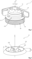
- FIG. 1 is a perspective, partial and schematic representation of an embodiment of a smoke detector 1.
- the rings 171 may, during their manufacture, be molded in one go to form a single piece.
- the cover 13 and the upper face 15 of the housing 19 close the chamber at its two axial ends.
- Electronic components of the optical chamber such as for example an LED and a photodetector (not shown in the Figure 1 ), are fixed to the face 15 or to the cover 13.
- the mobile assembly 11 has several functions which will be described later in more detail in relation to the Figure 3 .
- the housing 19 also contains all the electronic circuits necessary for the operation of the detector 1.
- the LED and the photodetector are notably connected to these circuits.
- the angle ⁇ is generally the same for all the rings 171 of the same stack. However, it may alternatively be different depending on the embodiment.
- the height h 1 of an assembly pad 172 is for example between 0.1 and 3 cm, preferably between 0.5 and 1.5 cm, the height h 1 being preferably equal to approximately 0.6 cm, for example equal to 0.6 cm.
- the height h 1 is preferably less than the height h 2 so that the baffles prevent direct external light.
- FIG. 3 is a representation by views (A), (B) and (C), partial and schematic, respectively lateral, from above and in perspective, of an embodiment of a mobile assembly 11 of the detector 1 of the Figure 1 .
- the mobile assembly 11 is, in the embodiment of the Figure 3 , external to the stack of elements 17. Thus, the mobile assembly 11 rotates around the stack of elements 17 along the Z axis.
- the movable assembly 11 is preferably driven by a motor (placed in the housing 19), which allows its rotation to be generated automatically. Alternatively, the movable assembly 11 can be rotated manually.
- the mobile assembly 11 comprises two arms 112 aligned, on either side of the axis of rotation.
- the term “arm” 112 refers to a part of the mobile assembly 11 which is connected to the axis Z of rotation and which extends in a direction orthogonal to this same axis Z.
- the number of arms 112 may be between 1 and 20, preferably between 1 and 6, the number of arms being preferably equal to 2.
- each arm 112 carries a module comprising legs 113, or a fin 111.
- a detector 1 with several arms 112 can receive one or more leg modules 113 and/or one or more fins 111.
- the legs 113 are, in the detector 1, interposed between two successive rings 171.
- the legs 113 rotate in the gaps between the rings 171.
- a leg 113 rotates in the gap created between the ring 171 closest to the cover 13 and the latter.
- the ring 171 closest to the upper face 15 of the housing 19 is carried by the latter.
- the legs 113 preferably have, in section, a shape corresponding to the shape of the section of the rings 171.
- the legs 113 are carried by an upright 115 of the arm 112 concerned.
- the rotation of the mobile assembly 11 causes the legs 113 to rotate between the rings 171 in the manner of a fork or a comb whose teeth would be inserted between the rings 171 from the outside.
- the length w 2 (view (C)) of a leg 113 depends on the width w 1 of the rings 171. It is generally equal to the width w 1 of the rings 171.
- the length w 2 is, for example, between 0.1 and 3 cm, preferably between 1 and 2.5 cm, the length w 2 being preferably equal to approximately 1.5 cm, for example equal to 1.5 cm.
- the width w 3 of a tab 113 is preferably constant.
- the width w 3 of a tab 113 is chosen according to the dimensions of the rings 171 and the thickness of the gaps between rings 171 in order to be able to rotate freely (with play) between two rings 171.
- the width w 3 is, for example, between 0.1 cm and 1.2 cm, preferably between 0.3 and 1 cm, the width w 3 being preferably approximately equal to 0.8 cm, for example equal to 0.8 cm.
- the legs 113 have disc arc shapes of the same diameter as the rings 171.
- the motor force is not sufficient.
- resistance to rotation can be detected and an alarm can be issued informing of a potential malfunction of the detector 1 due to obstruction(s).
- An operator can then manually drive the moving assembly 11, with a force greater than that of the motor, to remove, detach or unjam the obstruction(s).
- the surfaces of the legs 113 can also be equipped with brushes in order to scrub or brush the surface of the rings 171. This also makes it possible to compensate for any manufacturing tolerances of the rings 171 and to facilitate cleaning.
- the orientation of the brushes can also allow dust or dirt to be evacuated towards the outside of the baffles, away from the chamber.
- a second arm 112 of the mobile assembly 11 carries a fin 111.
- the fin 111 is carried by an upright 115 of the arm 112.
- the rotation of the mobile assembly 11 causes the fin 111 to rotate around the rings 171.
- the fin 111 has the shape of a curved rectangle, or a sail.
- the fin 111 is fixed to the upright 115 of the arm 112 of the mobile assembly 11 with an angle ⁇ .
- the angle ⁇ which corresponds to the angle between the arm 112 of the mobile assembly 11 on which the fin 111 is fixed and the tangent to the base of the fin 111, is for example between 1 and 170°, preferably between 10 and 90°, the angle ⁇ being preferably equal to approximately 50°, for example equal to 50°.
- the curvature of the fin 111, the angle ⁇ and the direction of rotation are designed to generate suction at the baffles.
- the fin 111 expels the air in front of it.
- the depression created behind the fin 111 causes suction of the air located inside the chamber. This suction allows the air in the chamber to be renewed.
- the sucked air also allows to carry away, in passing, the dust or deposits present on the rings 171, and thus to unblock the baffles.
- the photodetector when the photodetector detects scattered light, it can trigger a rotation of the moving assembly 11. Renewing the air in the chamber then removes the doubt. If the photodetector no longer detects scattered light, it is because it was a false alarm. Conversely, if the photodetector still receives a beam of scattered light, there is indeed smoke in the environment of detector 1.
- a removable and extendable rod (not shown) can further be attached to the top of the mobile assembly 11. This rod makes it possible to detect (by rotating) whether objects are present in the environment close to the detector 1 (a few tens of centimeters) to check whether safety distances set by standards are respected. For example, an alarm is emitted in the event of resistance to rotation to indicate that detector 1 is incorrectly positioned or that objects have been stored too close to it.
- FIG. 4 is a perspective representation and by views (A), (B) and (C), partial and schematic, of an embodiment of parts 13 and 15 of the detector 1 of the Figure 1 .
- the LED 151 and the photodetector 155 are electrically connected (connections 1510 and 1550) to the electronic control circuit 191 located in the housing 19, and are preferably carried by an electronic card carrying the circuit 191.
- the cover 13 further comprises an optical sub-chamber 133.
- the sub-chamber 133 is, like the optical chamber, black and opaque.
- the sub-chamber 133 is optically isolated from the chamber by screens in order to reduce the risk of light contamination of the sub-chamber 133 by external light.
- One 135 of the screens of the sub-chamber 133 is vertical and comprises an orifice 131 placed in front of the photodetector 155.
- the orifice 131 is arranged such that that the photodetector observes, through the orifice 131, the sub-chamber 133 at the level of the top of the location 153, therefore of the LED 151.
- the bases 152 and the internal faces of the orifices 132 are preferably conical and adapted to the respective ends of the pads 172 to facilitate assembly and ensure alignment of the stack of rings 171. In addition, this makes it possible to fix the position of the sub-chamber 133 relative to the LED 151.
- the detector 2 comprises, among other things, a housing 29, an upper face 25 of which carries a stack of elements 27.
- the embodiment shown in Figure 6 differs from the embodiment described in connection with the Figure 1 by the fact that the cleaning of the baffles is carried out by an assembly 21 inside the chamber.
- the assembly 21 is equipped with a module of legs 213 similar to the legs 113 of the mobile assembly 11 of the detector 1 of the Figure 1
- the legs 213 are fixed to the upper face 25 of the housing by a bracket 215 resting (foot 298) on the housing 29.
- the legs 213 of the assembly 21 move in the interstices formed between rings 271 of the elements 27.
- the assembly 21, in the embodiment of the Figure 6 is fixed and the stack of elements 27 is movable.
- the stack of elements 27 is, for example, fixed to one or more structures 297.
- Each structure 297 has, for example, an inverted "U" shape.
- the number of structures is chosen in order to allow the maximum possible air passages while ensuring the mechanical strength of the rings 271.
- the structures are connected, by a motor shaft 295, to a motor 293 (placed in the housing 29).
- the motor 293 generates the rotation of the stack 27, by the motor shaft 295 and the structure(s) 297.
- Each structure 297 is fixed, for example, to the set of rings 271 of the stack, by points of fasteners 299 located outside the base of the rings 271.
- FIG. 7 is a representation, by partial and schematic perspective views (A) and (B), of another embodiment of a smoke detector 3, not covered by the invention.
- the movable part 31 corresponds to a cylinder, the lateral face of which comprises a succession of vertical angular walls 311 defining indirect passages or baffles from the exterior to an optical chamber present inside said cylinder. All of these baffles form a baffle system.
- the fixed part 32 corresponds to another cylinder.
- the fixed part 32 forms a receiving ring for the movable part 31.
- the inner lateral surface of the fixed part 32 is provided with walls 321 having substantially the same shape as the baffles so that the movable part 31 can slide vertically in the fixed part 32.
- the sliding movement of the movable part in the fixed part makes it possible to clean the baffles. More particularly, the sliding of the walls 321 of the fixed part 32 in the baffles of the movable part 31 makes it possible to clear the baffles of any obstructions.
- Cleaning is carried out, for example, by manual action on part 31 so as to push it into part 32, against an elastic return force caused by a spring.
- Another advantage of the described embodiments and implementations is the ability of the detector to self-clean.
Landscapes
- General Physics & Mathematics (AREA)
- Physics & Mathematics (AREA)
- Chemical & Material Sciences (AREA)
- Analytical Chemistry (AREA)
- Emergency Management (AREA)
- Business, Economics & Management (AREA)
- Engineering & Computer Science (AREA)
- General Health & Medical Sciences (AREA)
- Immunology (AREA)
- Pathology (AREA)
- Biochemistry (AREA)
- Life Sciences & Earth Sciences (AREA)
- Health & Medical Sciences (AREA)
- Mechanical Engineering (AREA)
- Computer Security & Cryptography (AREA)
- Fire-Detection Mechanisms (AREA)
- Investigating Or Analysing Materials By Optical Means (AREA)
Claims (17)
- Ein Rauchdetektor (1; 2), der Folgendes aufweist:eine Detektionskammer;ein die Kammer umgebendes Ablenkblechsystem, das es ermöglicht, die Kammer von Außenlicht zu isolieren und Luft von außerhalb in das Innere der Kammer strömen zu lassen; undeinen mechanischen Aktor, der in der Lage ist, im Falle von Hindernissen zur Luftzirkulation die Ablenkbleche zu reinigen,wobei der Rauchdetektor dadurch gekennzeichnet ist, dass die Ablenkbleche durch ein aufeinanderfolgendes Stapeln von Elementen (17; 27) gebildet werden, die jeweils einen Ring (171; 271) aufweisen.
- Der Detektor nach Anspruch 1, der eine Vorrichtung aufweist, die so ausgelegt ist, dass sie einen Widerstand gegen die Drehung eines Motors des Aktors erfasst und einen Alarm auslöst, wenn die Kraft des Aktormotors nicht ausreicht, um die Ablenkbleche zu reinigen.
- Der Detektor nach Anspruch 1 oder 2, wobei der Querschnitt der Ringe (171; 271) eine allgemeine "U"- oder "V"-Form aufweist.
- Der Detektor nach einem der Ansprüche 1 bis 3, der ferner Folgendes aufweist:Ein Gehäuse (19; 29), das die Elemente (17; 27) aufnimmt; undeine Abdeckung (13), die den Stapel gegenüber dem Gehäuse (19; 29) verschließt, um die Kammer zu verschließen.
- Der Detektor nach einem der Ansprüche 1 bis 4, der ferner eine Baugruppe (11; 21) von Laschen (113; 213) aufweist, die zwischen zwei aufeinanderfolgenden Ringen (171; 271) eingeschoben sind, wobei jede Lasche (113; 213) eine allgemeine Form aufweist, die der allgemeinen Form des Querschnitts der Ringe (171; 271) entspricht.
- Der Detektor nach Anspruch 4 und 5, wobei die Baugruppe (11; 22) von dem Gehäuse (19; 29) getragen wird.
- Der Detektor nach Anspruch 5 oder 6, wobei die Baugruppe (11; 21) eine oder mehrere Flügel (111) außerhalb der Ringe (171; 271) aufweist.
- Der Detektor nach einem der Ansprüche 5 bis 7, wobei sich die Baugruppe (11) um die axiale Richtung des Stapels dreht.
- Der Detektor nach Anspruch 8, wobei die Baugruppe (11) von einem Motor (1913) angetrieben wird.
- Der Detektor nach einem der Ansprüche 5 bis 9, wobei die Baugruppe (11) außerhalb der Kammer liegt.
- Der Detektor nach einem der Ansprüche 5 bis 7, wobei die Baugruppe (21) feststehend ist.
- Der Detektor nach einem der Ansprüche 5 bis 7 und 11, wobei die Ringe (271) bewegbar sind und sich um die axiale Richtung des Stapels drehen.
- Der Detektor nach Anspruch 12, wobei der Stapel von einem Motor (293) angetrieben wird.
- Der Detektor nach einem der Ansprüche 5 bis 7 und 11 bis 13, wobei die Baugruppe (21) innerhalb der Kammer angeordnet ist.
- Der Detektor nach einem der Ansprüche 5 bis 14, wobei die Laschen (113; 213) mit Bürsten ausgestattet sind und der Stapel mit einem äußeren Insekten- und Staubschutzgitter ausgestattet ist, wobei das Gitter während der Drehung des Stapels durch die Bürsten gereinigt wird.
- Der Detektor nach einem der Ansprüche 1 bis 15, der ferner eine elektronische Steuerungsschaltung (191) aufweist.
- Der Detektor nach einem der Ansprüche 1 bis 16, der in der Kammer eine lichtemittierende Diode (151) und einen Fotodetektor (155) aufweist.
Applications Claiming Priority (1)
| Application Number | Priority Date | Filing Date | Title |
|---|---|---|---|
| FR1910818A FR3101468B1 (fr) | 2019-09-30 | 2019-09-30 | Détecteur de fumées |
Publications (2)
| Publication Number | Publication Date |
|---|---|
| EP3799004A1 EP3799004A1 (de) | 2021-03-31 |
| EP3799004B1 true EP3799004B1 (de) | 2025-04-16 |
Family
ID=69630371
Family Applications (1)
| Application Number | Title | Priority Date | Filing Date |
|---|---|---|---|
| EP20197971.3A Active EP3799004B1 (de) | 2019-09-30 | 2020-09-24 | Rauchmelder |
Country Status (3)
| Country | Link |
|---|---|
| US (1) | US11774359B2 (de) |
| EP (1) | EP3799004B1 (de) |
| FR (1) | FR3101468B1 (de) |
Families Citing this family (5)
| Publication number | Priority date | Publication date | Assignee | Title |
|---|---|---|---|---|
| CN113770136B (zh) * | 2021-05-14 | 2022-12-20 | 王志鑫 | 一种大气检测箱结构 |
| CN113467390B (zh) * | 2021-06-02 | 2024-04-30 | 中国大唐集团科学技术研究院有限公司 | 一种火电厂工控系统网络安全应急响应系统 |
| CN113560234A (zh) * | 2021-07-21 | 2021-10-29 | 徐馨 | 一种生产矿山用的安全报警设备 |
| CN114093115A (zh) * | 2021-11-30 | 2022-02-25 | 扬州工业职业技术学院 | 一种火灾烟雾报警装置 |
| CN119181196A (zh) * | 2024-09-11 | 2024-12-24 | 山东宝元消防科技有限公司 | 一种具备灭火结构的火灾报警装置 |
Citations (1)
| Publication number | Priority date | Publication date | Assignee | Title |
|---|---|---|---|---|
| DE102016121369B4 (de) * | 2016-11-08 | 2018-12-13 | Tq-Systems Gmbh | Rauchmesszelle |
Family Cites Families (11)
| Publication number | Priority date | Publication date | Assignee | Title |
|---|---|---|---|---|
| US3460124A (en) * | 1966-06-06 | 1969-08-05 | Interstate Eng Corp | Smoke detector |
| US4672217A (en) * | 1985-04-05 | 1987-06-09 | General Signal Corporation | Easily cleaned photoelectric smoke detector |
| US5581241A (en) * | 1994-08-12 | 1996-12-03 | Voice Products Inc. | Ultra-sensitive smoke detector |
| GB2327752B (en) * | 1997-07-26 | 2001-05-02 | Rafiki Prot Ltd | Optical scatter smoke sensor |
| US6778091B2 (en) * | 2001-01-09 | 2004-08-17 | Qualey, Iii James R. | Smoke chamber |
| JP2008077473A (ja) * | 2006-09-22 | 2008-04-03 | Hochiki Corp | 煙感知器 |
| US9679468B2 (en) | 2014-04-21 | 2017-06-13 | Tyco Fire & Security Gmbh | Device and apparatus for self-testing smoke detector baffle system |
| US9659485B2 (en) | 2014-04-23 | 2017-05-23 | Tyco Fire & Security Gmbh | Self-testing smoke detector with integrated smoke source |
| CN104794311A (zh) | 2015-05-15 | 2015-07-22 | 哈尔滨工业大学 | 一种时间自由条件下的全局最优双脉冲轨道转移方法 |
| CN105448028B (zh) * | 2015-11-19 | 2017-12-22 | 电子科技大学中山学院 | 一种基于塑料光纤传导的光检型烟感器 |
| CN209102569U (zh) * | 2018-09-28 | 2019-07-12 | 邯郸市美航电子科技有限公司 | 一种可靠性高的油烟检测装置 |
-
2019
- 2019-09-30 FR FR1910818A patent/FR3101468B1/fr active Active
-
2020
- 2020-09-24 EP EP20197971.3A patent/EP3799004B1/de active Active
- 2020-09-28 US US16/948,664 patent/US11774359B2/en active Active
Patent Citations (1)
| Publication number | Priority date | Publication date | Assignee | Title |
|---|---|---|---|---|
| DE102016121369B4 (de) * | 2016-11-08 | 2018-12-13 | Tq-Systems Gmbh | Rauchmesszelle |
Also Published As
| Publication number | Publication date |
|---|---|
| FR3101468A1 (fr) | 2021-04-02 |
| EP3799004A1 (de) | 2021-03-31 |
| FR3101468B1 (fr) | 2022-10-21 |
| US11774359B2 (en) | 2023-10-03 |
| US20210096071A1 (en) | 2021-04-01 |
Similar Documents
| Publication | Publication Date | Title |
|---|---|---|
| EP3799004A1 (de) | Rauchmelder | |
| EP3629073B1 (de) | Schutzvorrichtung eines optischen sensors eines lenkassistenzsystems für kraftfahrzeug | |
| CH686157A5 (fr) | Detecteur photoelectrique de fumee. | |
| EP1679469A1 (de) | Lichtsignalgerät | |
| EP0021887B1 (de) | Optoelektrische Detektionsvorrichtung, insbesondere für Laserstrahlen | |
| CA2970369C (fr) | Dispositif de filtrage optique pour la detection de gaz | |
| EP1193468A1 (de) | Optisches Messverfahren mit der Form eines Profils und Anwendung dieses Verfahrens für das Innenprofil einer Brillenfassung | |
| EP2263219B1 (de) | Kompakter rauchmelder | |
| EP3985631B1 (de) | Optischer rauchmelder | |
| WO2004079648A2 (fr) | Dispositif de detection optique pour compteur | |
| FR2656688A1 (fr) | Dispositif de mesure du niveau d'un liquide dans un reservoir par determination optique de la position d'un flotteur. | |
| FR3010492A1 (fr) | Dispositif d'eclairage | |
| EP1983495B1 (de) | Rauchmelder mit Vorrichtung an einem Reflektor zum Selektieren eines Lichtstrahles | |
| WO2016120276A1 (fr) | Procédés et dispositifs de détection de la contamination surfacique par des particules évoluant en air libre | |
| FR2690635A1 (fr) | Dispositif de protection pour un appareillage optique, et système optique comprenant un tel dispositif. | |
| EP1557805B1 (de) | Strahlungsdetektor mit Linsen und Spiegeln | |
| FR3046191A1 (fr) | Robot de nettoyage de piscine et methode de detection d'une immobilisation d'un tel robot | |
| EP1647955B1 (de) | Vorrichtung zur Erfassung und/oder Emission von Strahlung mit Spiegeln, insbesondere Infrarotstrahlung | |
| EP1722206B1 (de) | Bewegungssensor mit einstellbarem Detektionsbereich | |
| EP1522829A2 (de) | Vorrichtung zur Bestimmung eines Flüssigkeitsniveaus | |
| EP3498144B1 (de) | Bodenreinigungsroboter | |
| FR2995091A1 (fr) | Dispositif d'imagerie a grand angle de vue | |
| EP1089034A1 (de) | Beleuchtungseinrichtung mit Lichtleitstab für Kraftfahrzeug | |
| FR2922690A1 (fr) | Auxiliaire de commande, de signalisation et/ou d'avertissement a montage rapide. | |
| FR2553882A1 (fr) | Dispositif de detection thermique de points chauds |
Legal Events
| Date | Code | Title | Description |
|---|---|---|---|
| PUAI | Public reference made under article 153(3) epc to a published international application that has entered the european phase |
Free format text: ORIGINAL CODE: 0009012 |
|
| STAA | Information on the status of an ep patent application or granted ep patent |
Free format text: STATUS: REQUEST FOR EXAMINATION WAS MADE |
|
| 17P | Request for examination filed |
Effective date: 20200924 |
|
| AK | Designated contracting states |
Kind code of ref document: A1 Designated state(s): AL AT BE BG CH CY CZ DE DK EE ES FI FR GB GR HR HU IE IS IT LI LT LU LV MC MK MT NL NO PL PT RO RS SE SI SK SM TR |
|
| AX | Request for extension of the european patent |
Extension state: BA ME |
|
| STAA | Information on the status of an ep patent application or granted ep patent |
Free format text: STATUS: EXAMINATION IS IN PROGRESS |
|
| 17Q | First examination report despatched |
Effective date: 20221215 |
|
| RAP3 | Party data changed (applicant data changed or rights of an application transferred) |
Owner name: COMMISSARIAT A L'ENERGIE ATOMIQUE ET AUX ENERGIESALTERNATIVES |
|
| RIC1 | Information provided on ipc code assigned before grant |
Ipc: B08B 1/34 20240101ALI20241030BHEP Ipc: G08B 29/18 20060101ALI20241030BHEP Ipc: G08B 17/113 20060101ALI20241030BHEP Ipc: G08B 17/107 20060101AFI20241030BHEP |
|
| GRAP | Despatch of communication of intention to grant a patent |
Free format text: ORIGINAL CODE: EPIDOSNIGR1 |
|
| STAA | Information on the status of an ep patent application or granted ep patent |
Free format text: STATUS: GRANT OF PATENT IS INTENDED |
|
| INTG | Intention to grant announced |
Effective date: 20241209 |
|
| GRAS | Grant fee paid |
Free format text: ORIGINAL CODE: EPIDOSNIGR3 |
|
| GRAA | (expected) grant |
Free format text: ORIGINAL CODE: 0009210 |
|
| STAA | Information on the status of an ep patent application or granted ep patent |
Free format text: STATUS: THE PATENT HAS BEEN GRANTED |
|
| AK | Designated contracting states |
Kind code of ref document: B1 Designated state(s): AL AT BE BG CH CY CZ DE DK EE ES FI FR GB GR HR HU IE IS IT LI LT LU LV MC MK MT NL NO PL PT RO RS SE SI SK SM TR |
|
| REG | Reference to a national code |
Ref country code: GB Ref legal event code: FG4D Free format text: NOT ENGLISH |
|
| REG | Reference to a national code |
Ref country code: CH Ref legal event code: EP Ref country code: DE Ref legal event code: R096 Ref document number: 602020049453 Country of ref document: DE |
|
| REG | Reference to a national code |
Ref country code: IE Ref legal event code: FG4D Free format text: LANGUAGE OF EP DOCUMENT: FRENCH |
|
| REG | Reference to a national code |
Ref country code: NL Ref legal event code: MP Effective date: 20250416 |
|
| PG25 | Lapsed in a contracting state [announced via postgrant information from national office to epo] |
Ref country code: NL Free format text: LAPSE BECAUSE OF FAILURE TO SUBMIT A TRANSLATION OF THE DESCRIPTION OR TO PAY THE FEE WITHIN THE PRESCRIBED TIME-LIMIT Effective date: 20250416 |
|
| REG | Reference to a national code |
Ref country code: AT Ref legal event code: MK05 Ref document number: 1786321 Country of ref document: AT Kind code of ref document: T Effective date: 20250416 |
|
| PG25 | Lapsed in a contracting state [announced via postgrant information from national office to epo] |
Ref country code: PT Free format text: LAPSE BECAUSE OF FAILURE TO SUBMIT A TRANSLATION OF THE DESCRIPTION OR TO PAY THE FEE WITHIN THE PRESCRIBED TIME-LIMIT Effective date: 20250818 Ref country code: ES Free format text: LAPSE BECAUSE OF FAILURE TO SUBMIT A TRANSLATION OF THE DESCRIPTION OR TO PAY THE FEE WITHIN THE PRESCRIBED TIME-LIMIT Effective date: 20250416 Ref country code: FI Free format text: LAPSE BECAUSE OF FAILURE TO SUBMIT A TRANSLATION OF THE DESCRIPTION OR TO PAY THE FEE WITHIN THE PRESCRIBED TIME-LIMIT Effective date: 20250416 |
|
| PGFP | Annual fee paid to national office [announced via postgrant information from national office to epo] |
Ref country code: DE Payment date: 20250919 Year of fee payment: 6 |
|
| REG | Reference to a national code |
Ref country code: LT Ref legal event code: MG9D |
|
| PG25 | Lapsed in a contracting state [announced via postgrant information from national office to epo] |
Ref country code: GR Free format text: LAPSE BECAUSE OF FAILURE TO SUBMIT A TRANSLATION OF THE DESCRIPTION OR TO PAY THE FEE WITHIN THE PRESCRIBED TIME-LIMIT Effective date: 20250717 Ref country code: NO Free format text: LAPSE BECAUSE OF FAILURE TO SUBMIT A TRANSLATION OF THE DESCRIPTION OR TO PAY THE FEE WITHIN THE PRESCRIBED TIME-LIMIT Effective date: 20250716 |
|
| PG25 | Lapsed in a contracting state [announced via postgrant information from national office to epo] |
Ref country code: PL Free format text: LAPSE BECAUSE OF FAILURE TO SUBMIT A TRANSLATION OF THE DESCRIPTION OR TO PAY THE FEE WITHIN THE PRESCRIBED TIME-LIMIT Effective date: 20250416 |
|
| PG25 | Lapsed in a contracting state [announced via postgrant information from national office to epo] |
Ref country code: BG Free format text: LAPSE BECAUSE OF FAILURE TO SUBMIT A TRANSLATION OF THE DESCRIPTION OR TO PAY THE FEE WITHIN THE PRESCRIBED TIME-LIMIT Effective date: 20250416 |
|
| PGFP | Annual fee paid to national office [announced via postgrant information from national office to epo] |
Ref country code: GB Payment date: 20250923 Year of fee payment: 6 |
|
| PG25 | Lapsed in a contracting state [announced via postgrant information from national office to epo] |
Ref country code: HR Free format text: LAPSE BECAUSE OF FAILURE TO SUBMIT A TRANSLATION OF THE DESCRIPTION OR TO PAY THE FEE WITHIN THE PRESCRIBED TIME-LIMIT Effective date: 20250416 |
|
| PG25 | Lapsed in a contracting state [announced via postgrant information from national office to epo] |
Ref country code: AT Free format text: LAPSE BECAUSE OF FAILURE TO SUBMIT A TRANSLATION OF THE DESCRIPTION OR TO PAY THE FEE WITHIN THE PRESCRIBED TIME-LIMIT Effective date: 20250416 |
|
| PGFP | Annual fee paid to national office [announced via postgrant information from national office to epo] |
Ref country code: FR Payment date: 20250917 Year of fee payment: 6 |
|
| PG25 | Lapsed in a contracting state [announced via postgrant information from national office to epo] |
Ref country code: RS Free format text: LAPSE BECAUSE OF FAILURE TO SUBMIT A TRANSLATION OF THE DESCRIPTION OR TO PAY THE FEE WITHIN THE PRESCRIBED TIME-LIMIT Effective date: 20250716 |
|
| PG25 | Lapsed in a contracting state [announced via postgrant information from national office to epo] |
Ref country code: IS Free format text: LAPSE BECAUSE OF FAILURE TO SUBMIT A TRANSLATION OF THE DESCRIPTION OR TO PAY THE FEE WITHIN THE PRESCRIBED TIME-LIMIT Effective date: 20250816 |
|
| PG25 | Lapsed in a contracting state [announced via postgrant information from national office to epo] |
Ref country code: LV Free format text: LAPSE BECAUSE OF FAILURE TO SUBMIT A TRANSLATION OF THE DESCRIPTION OR TO PAY THE FEE WITHIN THE PRESCRIBED TIME-LIMIT Effective date: 20250416 |
|
| PG25 | Lapsed in a contracting state [announced via postgrant information from national office to epo] |
Ref country code: DK Free format text: LAPSE BECAUSE OF FAILURE TO SUBMIT A TRANSLATION OF THE DESCRIPTION OR TO PAY THE FEE WITHIN THE PRESCRIBED TIME-LIMIT Effective date: 20250416 Ref country code: SM Free format text: LAPSE BECAUSE OF FAILURE TO SUBMIT A TRANSLATION OF THE DESCRIPTION OR TO PAY THE FEE WITHIN THE PRESCRIBED TIME-LIMIT Effective date: 20250416 |
|
| REG | Reference to a national code |
Ref country code: DE Ref legal event code: R097 Ref document number: 602020049453 Country of ref document: DE |
|
| PG25 | Lapsed in a contracting state [announced via postgrant information from national office to epo] |
Ref country code: CZ Free format text: LAPSE BECAUSE OF FAILURE TO SUBMIT A TRANSLATION OF THE DESCRIPTION OR TO PAY THE FEE WITHIN THE PRESCRIBED TIME-LIMIT Effective date: 20250416 |
|
| PG25 | Lapsed in a contracting state [announced via postgrant information from national office to epo] |
Ref country code: EE Free format text: LAPSE BECAUSE OF FAILURE TO SUBMIT A TRANSLATION OF THE DESCRIPTION OR TO PAY THE FEE WITHIN THE PRESCRIBED TIME-LIMIT Effective date: 20250416 |
|
| PG25 | Lapsed in a contracting state [announced via postgrant information from national office to epo] |
Ref country code: SK Free format text: LAPSE BECAUSE OF FAILURE TO SUBMIT A TRANSLATION OF THE DESCRIPTION OR TO PAY THE FEE WITHIN THE PRESCRIBED TIME-LIMIT Effective date: 20250416 Ref country code: RO Free format text: LAPSE BECAUSE OF FAILURE TO SUBMIT A TRANSLATION OF THE DESCRIPTION OR TO PAY THE FEE WITHIN THE PRESCRIBED TIME-LIMIT Effective date: 20250416 |
|
| PG25 | Lapsed in a contracting state [announced via postgrant information from national office to epo] |
Ref country code: IT Free format text: LAPSE BECAUSE OF FAILURE TO SUBMIT A TRANSLATION OF THE DESCRIPTION OR TO PAY THE FEE WITHIN THE PRESCRIBED TIME-LIMIT Effective date: 20250416 |
|
| PLBE | No opposition filed within time limit |
Free format text: ORIGINAL CODE: 0009261 |
|
| STAA | Information on the status of an ep patent application or granted ep patent |
Free format text: STATUS: NO OPPOSITION FILED WITHIN TIME LIMIT |
|
| REG | Reference to a national code |
Ref country code: CH Ref legal event code: L10 Free format text: ST27 STATUS EVENT CODE: U-0-0-L10-L00 (AS PROVIDED BY THE NATIONAL OFFICE) Effective date: 20260225 |
|
| 26N | No opposition filed |
Effective date: 20260119 |
|
| REG | Reference to a national code |
Ref country code: CH Ref legal event code: H13 Free format text: ST27 STATUS EVENT CODE: U-0-0-H10-H13 (AS PROVIDED BY THE NATIONAL OFFICE) Effective date: 20260504 |