EP3798654B1 - Magnetresonanzvorrichtung mit einer mikrofoneinheit - Google Patents
Magnetresonanzvorrichtung mit einer mikrofoneinheit Download PDFInfo
- Publication number
- EP3798654B1 EP3798654B1 EP19199828.5A EP19199828A EP3798654B1 EP 3798654 B1 EP3798654 B1 EP 3798654B1 EP 19199828 A EP19199828 A EP 19199828A EP 3798654 B1 EP3798654 B1 EP 3798654B1
- Authority
- EP
- European Patent Office
- Prior art keywords
- microphone
- unit
- board
- magnetic resonance
- patient
- Prior art date
- Legal status (The legal status is an assumption and is not a legal conclusion. Google has not performed a legal analysis and makes no representation as to the accuracy of the status listed.)
- Active
Links
Images


Classifications
-
- G—PHYSICS
- G01—MEASURING; TESTING
- G01R—MEASURING ELECTRIC VARIABLES; MEASURING MAGNETIC VARIABLES
- G01R33/00—Arrangements or instruments for measuring magnetic variables
- G01R33/20—Arrangements or instruments for measuring magnetic variables involving magnetic resonance
- G01R33/28—Details of apparatus provided for in groups G01R33/44 - G01R33/64
- G01R33/283—Intercom or optical viewing arrangements, structurally associated with NMR apparatus
Definitions
- the present invention relates to a magnetic resonance device with a scanner unit, a patient receiving area at least partially surrounded by the scanner unit, wherein the scanner unit comprises a housing unit which at least partially surrounds the patient receiving area, and a communication unit with at least one microphone unit.
- the magnetic resonance device usually has a communication unit.
- a communication unit can have an input unit and an output unit on the patient side, such as headphones and a microphone.
- the communication unit can also have an input unit and an output unit on the user side.
- Such communication units are known, for example, from the US2018/128888 A1 or the DE102004042100 A1 known.
- the microphone can also be installed within a High frequency antenna unit that is fixedly arranged and/or integrated within a scanner unit of the magnetic resonance device.
- the microphone is arranged particularly close to a noise source, in particular the gradient coil unit of the scanner unit, during the magnetic resonance examination.
- sound waves and vibrations can preferably be transmitted directly to the microphone and thus also lead to undesirable noise during communication between the operating personnel and the patient.
- the present invention is based in particular on the object of providing an arrangement of a microphone of the communication unit that is decoupled from noise.
- the object is achieved by the features of the independent claim.
- Advantageous embodiments are described in the subclaims.
- the invention is based on a magnetic resonance device with a scanner unit, a patient receiving area at least partially surrounded by the scanner unit, wherein the scanner unit comprises a housing unit which at least partially surrounds the patient receiving area, and a communication unit with at least one microphone unit.
- the at least one microphone unit has at least one decoupling element, wherein the at least one microphone unit is arranged on the housing unit in a vibration-decoupled manner by means of the decoupling element.
- the scanner unit typically has a base magnet to generate a base magnetic field that is as homogeneous and constant as possible.
- the scanner unit has a gradient coil unit that is designed to generate a gradient field during a magnetic resonance examination, and a high-frequency antenna unit.
- the high-frequency antenna unit is permanently arranged and/or integrated within the scanner unit and is designed to transmit magnetic resonance sequences in the patient recording areas.
- the housing unit is preferably the unit within the scanner unit that is arranged directly around the patient receiving area of the magnetic resonance device.
- the housing unit surrounding the patient receiving area can also be designed as one piece and/or as one piece with the high-frequency antenna unit.
- the housing unit comprises a limitation of the patient receiving area in the radial direction.
- the patient receiving area is typically surrounded by the scanner unit in a cylindrical shape.
- the patient receiving area is typically surrounded by the housing unit in a cylindrical shape.
- the patient receiving area is designed to receive the patient, in particular the area of the patient to be examined, during a magnetic resonance examination.
- the patient is preferably supported and/or positioned on a patient table that can be moved within the patient receiving area in a horizontal direction, in particular in the z-direction and/or in the longitudinal extension of the patient table.
- the communication unit is designed for communication between the patient and a medical operator during a magnetic resonance examination on the patient.
- the medical operator can preferably give the patient instructions, for example a breathing command to the patient, during the magnetic resonance device.
- the patient can also inform the medical operator of his or her condition and/or any discomfort, for example if the patient is anxious due to the narrow space in the patient admission area of a magnetic resonance device.
- the communication unit on the user side preferably has a user input unit, in particular an acoustic input unit such as a microphone unit, and a user output unit, in particular an acoustic output unit such as a loudspeaker unit,
- the communication unit on the patient side also has a patient input unit and a patient output unit.
- the output unit can comprise an optical output unit.
- the output unit comprises an acoustic output unit, such as headphones.
- the input unit comprises a microphone unit with at least one microphone.
- the decoupling element is preferably designed to decouple vibrations and/or structure-borne sound waves, which are generated in particular by the gradient coil unit, from the microphone unit.
- the decoupling element can be formed from all elements that appear to be useful to the person skilled in the art and that enable advantageous decoupling of vibrations and/or structure-borne sound waves.
- the microphone unit is arranged on the housing unit surrounding the patient reception area.
- the microphone unit is arranged on the housing unit, in particular on the housing unit surrounding the patient reception area, in such a way that a detection area of a microphone of the microphone unit extends into the patient reception area.
- the design according to the invention advantageously makes it possible to arrange the microphone unit in a way that is decoupled from noise.
- the communication unit comprises two or more microphone units which are distributed on the housing unit and/or stored.
- the individual Microphone units are arranged and/or stored distributed on the housing unit, in particular on the housing unit surrounding the patient reception area, so that reliable detection of communication signals from the patient can be achieved within the entire patient reception area. In particular, reliable detection of communication signals from the patient can also be achieved regardless of the position of the patient.
- the housing unit has at least one recess for accommodating the at least one microphone unit. Due to the recess, a particularly space-saving arrangement of the at least one microphone unit on the housing unit, in particular on the housing unit surrounding the patient receiving area, can be achieved. In particular, such an arrangement can be provided in the vicinity of the patient during a magnetic resonance examination.
- the housing unit in particular the housing unit surrounding the patient receiving area, has its own recess for each microphone unit of the communication unit.
- the at least one decoupling element is arranged on an edge region of the recess.
- a soundproof arrangement of the at least one microphone unit on the housing unit can be achieved in this way.
- the edge region of the at least one recess preferably comprises a transition from the at least one microphone unit to the housing unit, in particular to the housing unit surrounding the patient receiving area.
- Such a transition is particularly critical with regard to sound decoupling and/or vibration decoupling.
- the decoupling element which preferably seals the entire edge region of the at least one recess, however, a soundproof and/or sound-decoupled and/or vibration-decoupled arrangement can be achieved particularly advantageously.
- the microphone unit on the housing unit in particular the housing unit surrounding the patient reception area. In addition, this can advantageously reduce and/or avoid noise when recording communication signals from the patient.
- the at least one microphone unit has a microphone board with a microphone.
- a microphone board preferably comprises a circuit board and/or a printed circuit board on which the microphone is arranged.
- other components that appear useful to the person skilled in the art, in particular electronic components, such as components for supply voltage stabilization and/or for overvoltage protection of the microphone, etc., can be arranged on the microphone board, in particular the circuit board.
- the microphone can be designed to be particularly small, for example as a miniaturized microphone and/or as a MEMS (Micro Electro Mechanical System) microphone.
- a microphone preferably has a length and/or width in the mm range.
- Individual components of a miniaturized microphone and/or a MEMS microphone can also have dimensions in the pm range.
- a maximum length and/or a maximum width of the miniaturized microphone and/or the MEMS microphone is 10 mm.
- a maximum length and/or a maximum width of the miniaturized microphone and/or the MEMS microphone is 8 mm.
- a maximum length and/or a maximum width of the miniaturized microphone and/or the MEMS microphone is 6 mm.
- a maximum length and/or a maximum width of the miniaturized microphone and/or the MEMS microphone is 4 mm. This makes it possible to provide a particularly compact and space-saving microphone for the at least one microphone unit and thus also to design the microphone unit to be particularly space-saving and/or compact.
- the microphone is arranged on a side of the microphone board facing the patient reception area. This advantageously makes it possible to provide an uncovered detection area of the microphone into the patient reception area.
- the microphone can also be arranged on the side of the microphone board facing away from the patient reception area, in which case the microphone board can preferably have a sound opening for the microphone.
- the at least one microphone unit has a connection board, preferably with an interface.
- the connection board preferably comprises a circuit board and/or printed circuit board on which an interface of the microphone unit is arranged.
- further components that appear useful to the person skilled in the art, in particular electronic components, can be arranged on the connection board, in particular the circuit board and/or printed circuit board.
- the interface is preferably arranged on a side of the connection board facing away from the microphone board.
- communication signals in particular communication signals detected by means of the microphone, can preferably be transmitted to further units of the communication unit, such as a processing unit of the communication unit.
- An advantageous power supply for the at least one microphone unit can also be provided by means of the interface.
- connection board is preferably arranged at a distance from the microphone board, whereby between the connection board and the An intermediate layer is arranged between the microphone board and the microphone board.
- connection board and the microphone board have a substantially identical base area.
- the connection board can be arranged and/or designed to be congruent with the microphone board.
- the at least one microphone unit has a connecting element for mechanically connecting the connection board to the microphone board.
- the connecting element preferably comprises a securing element in order to arrange the microphone board securely and/or captively on the connection board.
- the connecting element can comprise, for example, a screw and/or a locking element and/or a clamping element, etc.
- the microphone board and/or the connection board preferably have an element corresponding to the connecting element that enables a mechanical connection. If the connecting element is a screw, for example, the corresponding elements can comprise recesses for the screw to pass through and/or threaded receptacles, such as in particular a screw nut.
- This embodiment of the invention makes it possible to achieve a particularly simple mechanical connection of the microphone board to the connection board and/or a simple securing of the microphone board to the connection board.
- This can be achieved particularly advantageously if the connecting element comprises a screw, in particular a captively secured screw.
- the microphone board can be easily removed and/or replaced.
- the microphone board can be removed and/or replaced from the scanner unit without dismantling the housing shell surrounding the patient reception area.
- the microphone board can also be removed and/or replaced independently of the connection board.
- the at least one microphone unit has two or more contact elements that are variable in length and are arranged between the connection board and the microphone board.
- the two or more contact elements that are variable in length each comprise a contact spring.
- the two or more contact springs that are variable in length are preferably arranged distributed over a surface of the connection board and/or the microphone board, so that the distance between the connection board and the microphone board can be as uniform as possible.
- the arrangement of at least two contact elements that are variable in length can advantageously provide a closed circuit between the connection board and the microphone board.
- a secure and/or redundant signal transmission can be provided between the microphone board and the connection board.
- a fastening element and/or securing element for fastening and/or securing the microphone board to the connection board can be used.
- a fastening screw and/or locking screw can be designed as a voltage-carrying element between the microphone board and the connection board.
- the contact element with variable length i.e. the contact spring
- the contact element with variable length is designed to establish a contact, in particular an electrical contact, between the connection board and the microphone board.
- the contact element with variable length has a maximum length at which the contact element with variable length is preferably arranged in a relaxed manner.
- the contact element with variable length can also be arranged in a compressed state between the connection board and the microphone board.
- the contact element with variable length is preferably also designed as a miniaturized contact element.
- the contact element with variable length i.e. the contact spring
- a miniature contact spring preferably has a length in the mm range.
- a maximum length of the miniature contact spring is 6 mm.
- a maximum length of the miniature contact spring is 5 mm.
- a maximum length of the miniature contact spring is 4 mm.
- a maximum length of the miniature contact spring is 3 mm.
- a contact surface of the miniature contact spring for contacting the connection board and/or the microphone board is preferably smaller than 1 mm.
- the contact surface of the miniature contact spring can preferably be smaller than 0.8 mm.
- the microphone board has concentric conductor tracks that are interrupted at at least one point.
- the microphone board and/or the connection board comprises a circular circuit board in which orientation cannot be ensured, wherein the concentric conductor tracks enable simple assembly of the connection board and/or the microphone board. By interrupting the concentric conductor tracks, unwanted eddy currents within the microphone unit can be prevented.
- simple arrangement and/or contacting of the at least one contact element with variable length or of the two or more contact elements with variable length can be enabled by means of the conductor tracks.
- the concentric conductor tracks are arranged on a side of the microphone board facing the connection board.
- the concentric conductor tracks can also be arranged on the connection board, in particular on a side of the connection board facing the microphone board, so that a simple exchange of contact elements with variable lengths that are arranged between the connection board and the microphone board can be achieved. It is true that the interruption of the concentric conductor tracks may require additional contact elements with variable lengths in order to avoid a random arrangement of one of the contact elements with variable lengths at the interruption of the concentric conductor tracks. Nevertheless, such a design is a simple implementation of a contact between the connection board and the microphone board.
- the at least one microphone unit has at least one further electronic component.
- the at least one further electronic component is arranged on the microphone board.
- Such an electronic component can, for example, comprise a diode, in particular a Z-diode or Zener diode, and/or a capacitor and/or further electronic components that appear useful to the person skilled in the art.
- a voltage supply of the microphone unit, in particular for the microphone can advantageously be protected by means of a diode.
- advantageous voltage stabilization can also be achieved by means of a capacitor, for example, during operation of the microphone unit.
- the at least one microphone unit has a maximum diameter of 2 cm.
- the microphone unit preferably has a maximum diameter of 1.8 cm.
- the microphone unit preferably has a maximum diameter of 1.6 cm.
- the microphone unit preferably has a maximum diameter of 1.4 cm.
- the microphone unit preferably has a maximum diameter of 1.2 cm. It is particularly advantageous for the microphone board and/or the connection board to have a maximum diameter of 1.8 cm. It is particularly advantageous for the microphone board and/or the connection board to have a maximum diameter of 1.6 cm. It is particularly advantageous for the microphone board and/or the connection board to have a maximum diameter of 1.4 cm. It is particularly advantageous for the microphone board and/or the connection board to have a maximum diameter of 1.2 cm.
- the microphone board and/or the connection board it is particularly advantageous for the microphone board and/or the connection board to have a maximum diameter of 1.0 cm. It is particularly advantageous if the microphone board and/or the connection board have a maximum diameter of 0.9 cm. This allows a particularly compact microphone unit to be used for communication between the patient and the medical staff during a magnetic resonance examination. In addition, openings, in particular sound openings, and/or recesses within the housing unit can be kept particularly small in this way, thus reducing sound transmission and/or vibration transmission into the patient reception area.
- the scanner unit has a high-frequency antenna unit that is fixedly arranged in the scanner unit, wherein the high-frequency antenna unit is formed integrally with the housing unit.
- the at least one microphone unit is integrated directly into the high-frequency antenna unit.
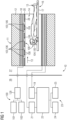
- the magnetic resonance device 10 comprises a scanner unit 11 formed by a magnet unit, which comprises a superconducting base magnet 12 for generating a strong and in particular constant base magnetic field 13.
- the magnetic resonance device 10 has a patient receiving area 14 for receiving a patient 15.
- the patient receiving area 14 in the present embodiment is cylindrical and is cylindrically surrounded in a circumferential direction by the scanner unit 11. In principle, however, a different design of the patient receiving area 14 is conceivable at any time.
- the patient 15 can be pushed and/or driven into the patient receiving area 14 by means of a patient support device 16 of the magnetic resonance device 10.
- the patient support device 16 has a patient table 17 designed to be movable within the patient receiving area 14.
- the scanner unit 11, in particular the magnet unit, further comprises a gradient coil unit 18 for generating magnetic field gradients that are used for spatial coding during imaging.
- the gradient coil unit 18 is controlled by a gradient control unit 19 of the magnetic resonance device 10.
- the scanner unit 11, in particular the magnet unit further comprises a high-frequency antenna unit 20 for exciting a polarization that occurs in the basic magnetic field 13 generated by the basic magnet 12.
- the high-frequency antenna unit 20 is controlled by a high-frequency antenna control unit 21 of the magnetic resonance device 10 and radiates high-frequency magnetic resonance sequences into an examination room that is essentially formed by the patient receiving area 14 of the magnetic resonance device 10.
- the scanner unit 11, in particular the magnet unit, further comprises a housing unit 28, wherein the housing unit 28 directly surrounds the patient receiving area 14 in a cylindrical shape.
- the housing unit 28 is formed integrally and/or in one piece with the high-frequency antenna unit 20, so that in the present exemplary embodiment the high-frequency antenna unit 20 also directly surrounds the patient receiving area 14 in a cylindrical shape.
- the magnetic resonance device 10 has a system control unit 22 for controlling the base magnet 12, the gradient control unit 19 and for controlling the radio-frequency antenna control unit 21.
- the system control unit 22 centrally controls the magnetic resonance device 10, such as, for example, carrying out a predetermined imaging gradient echo sequence.
- the system control unit 22 includes an evaluation unit (not shown in detail) for evaluating medical image data that is acquired during the magnetic resonance examination.
- the magnetic resonance device 10 comprises a user interface 23, which is connected to the system control unit 22.
- Control information such as imaging parameters, as well as reconstructed magnetic resonance images can be displayed on a display unit 24, for example on at least one monitor, of the user interface 23 for medical operators.
- the user interface 23 also has an input unit 25, by means of which information and/or parameters can be entered by the medical operators during a measurement process.
- the magnetic resonance device 10 For communication between the patient 15 and the medical operating personnel during a magnetic resonance examination, the magnetic resonance device 10 has a communication unit 100.
- the communication unit 100 has a user input unit 101 and a user output unit 102 on the user side.
- the user input unit In the present embodiment, 101 comprises an acoustic user input unit, such as a microphone.
- the user output unit 102 comprises an acoustic user output unit, such as a loudspeaker.
- the communication unit 100 on the user side can also comprise an optical input unit and/or an optical output unit, such as a monitor and/or a display.
- the user input unit 101 and a user output unit 102 are arranged within a monitoring room 26.
- the monitoring room 26 is arranged separately from an examination room 27 in which the magnetic resonance device 10 is arranged.
- the monitoring room 26 and the examination room 27 are shielded from one another with regard to an exchange of high-frequency signals and/or electromagnetic radiation.
- the system control unit is preferably also arranged together with the user interface within the monitoring room 26.
- the communication unit 100 further comprises a patient input unit 103 and a patient output unit 104 on the patient side.
- the patient input unit 103 and the patient output unit 104 are arranged within the examination room 27.
- the patient output unit 104 comprises an acoustic patient output unit 104, which comprises a headphone 105.
- the patient input unit 103 comprises an acoustic patient input unit 103, which comprises at least one microphone unit 106.
- the at least one microphone unit 106 is arranged on the housing unit 28, in the present embodiment also on the high-frequency antenna unit 20.
- the communication unit 100 comprises a plurality of microphone units 106, which are arranged distributed over the patient receiving area 14 on the housing unit 28, in the present embodiment also on the high-frequency antenna unit 20, so that regardless of a patient position, a Communication between the patient 15 and the medical staff is possible.
- the magnetic resonance device 10 shown can of course include further components that magnetic resonance devices 10 usually have.
- a general mode of operation of a magnetic resonance device 10 is also known to the person skilled in the art, so that a detailed description of the further components is omitted.
- a structure of the microphone units 106 is explained in more detail below using a single microphone unit 106, whereby the other microphone units 106 are identical to the microphone unit 106 described in more detail.
- the structure of the microphone unit 106 is shown in the Fig. 2 to 6 described and illustrated in more detail.
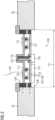
- the microphone unit 106 has at least one decoupling element 107, wherein by means of the decoupling element 107 a vibration-decoupled arrangement and/or mounting of the microphone unit 106 on the housing unit 28, in the present embodiment also on the high-frequency antenna unit 20, takes place ( Fig. 2 ).
- the microphone unit 106 comprises two decoupling elements 107, each of which comprises a rubber ring.
- the microphone unit 106 can also have only a single decoupling element 107 or more than two decoupling elements 107.
- the individual decoupling elements 107 can also have an element other than a rubber ring.
- the housing unit 28, in the present embodiment also the high-frequency antenna unit 20 has a recess 108 for each of the microphone units 106 ( Fig.1 and 2 ).
- the individual recesses 108 are each designed to accommodate one of the Microphone units 106 are designed.
- the individual recesses 106 each have a circular recess 106.
- the individual microphone units 106 also have a circular design.
- the two decoupling elements 107 of the microphone unit 106 are arranged on an outer edge region 109 of the microphone unit 106 in the radial direction 110 ( Fig. 2 ).
- a transition between the microphone unit 106 and the high-frequency antenna unit 20 can be made soundproof and/or vibration-proof.
- the microphone unit 106 is designed to be particularly space-saving and has a maximum diameter 111 of 2 cm. In an alternative embodiment of the microphone unit 106, it can also have a maximum diameter that is greater than 2 cm.
- the microphone unit 106 further comprises a microphone board 112 and a connection board 113 ( Fig. 2 to 6 ).
- the microphone board 112 comprises a circular circuit board.
- the connection board 113 also comprises a circular circuit board, wherein the microphone board 112 and the connection board 113 have a substantially identical diameter 114 ( Fig. 2 to 6 ). Due to the space-saving design of the microphone unit 106 in the present embodiment, the microphone board 112 and the connection board 113 are also particularly compact and small in the present embodiment.
- the microphone board 112 and the connection board 113 preferably have a maximum diameter 114 of 1.5 cm.
- the microphone board 112 and the connection board 113 preferably have a maximum diameter 114 of 1.0 cm.
- the microphone board 112 comprises a microphone, which in the present embodiment comprises a miniaturized microphone and/or a MEMS (Micro Electro Mechanical System) microphone 115 ( Fig. 2 and 6 ).
- the miniaturized microphone and/or the MEMS microphone 115 is attached to a bottom side, in particular on a side 116 of the microphone unit 106, in particular of the microphone board 112, facing the patient receiving area 14.
- the miniaturized microphone and/or the MEMS microphone 115 has a length and/or width in the mm range.
- the miniaturized microphone and/or the MEMS microphone 115 advantageously has a maximum length and/or a maximum width of 10 mm.
- the miniaturized microphone and/or the MEMS microphone 115 advantageously has a maximum length and/or a maximum width of 6 mm.
- the microphone unit 106 in particular in a non-miniaturized embodiment of the microphone unit 106, the microphone can also have a length greater than 10 mm.
- the microphone board 112 has at least one further electronic component 117, which is also arranged on the side 116 of the microphone unit 106, in particular of the microphone board 112, facing the patient receiving area 14 ( Fig.6 ).
- the microphone board 112 has two further electronic components 117, although the invention is not limited to two further electronic components 117.
- a first electronic component 117 of the two further electronic components 117 comprises a diode 118, in particular a Z-diode and/or a Zener diode, which is designed to protect a voltage supply of the miniaturized microphone and/or the MEMS microphone 115.
- a second electronic component 117 of the two further electronic components 117 comprises a capacitor which is designed to stabilize the voltage and/or to divert RF interference signals. If the microphone comprises a larger microphone than a miniaturized microphone and/or a MEMS microphone 115, at least one further component 117, such as the diode 118, can be arranged and/or integrated within the microphone. In addition, the further component 117 can also be arranged on a side of the microphone board 112 facing away from the patient receiving area 14.
- the microphone board 112 On an upper side, in particular on a side 119 facing away from the patient receiving area 14 and/or a side 119 facing the connection board 113, the microphone board 112 has conductor tracks 120 ( Fig.5 ). In the present embodiment, the microphone board 112 comprises four conductor tracks 120. In an alternative embodiment of the microphone board 112, this can also have more than four conductor tracks 120 or fewer than four conductor tracks 120.
- the four conductor tracks 120 are designed as concentric conductor tracks 120 with different diameters, wherein the individual conductor tracks 120 are interrupted at one point in order to avoid undesirable eddy currents.
- the connection board 113 comprises an interface 129 which is arranged on a top side, in particular on a side 121 of the connection board 113 facing away from the microphone board 112 ( Fig. 2 and 3 ).
- the interface 129 comprises four connections, whereby a signal exchange within the communication unit 100 and/or a voltage supply to the microphone unit 106 takes place by means of the four connections.
- the signal exchange within the communication unit 100 preferably takes place by means of signal cable 130 ( Fig. 2 and 3 ), for example electrical and/or optical signal cables.
- the communication unit 100 can also have an evaluation unit 128 and/or a control unit that controls and/or regulates a signal exchange of communication signals within the communication unit 100, in particular between the user side and the patient side of the communication unit 100 ( Fig.1 ).
- the microphone unit 106 further comprises a connecting element 122 for the mechanical connection between the connection board 113 and the microphone board 112 ( Fig.2 ).
- the connecting element 122 comprises a screw, in particular a screw designed to be captive.
- an alternative design of the connecting element to a screw is also possible.
- 122 is possible at any time, such as a locking element and/or a clamping element, etc.
- the connecting element 122 in particular the screw
- the microphone board 112 is securely arranged on the connection board 113.
- the connection board 113 has a circular recess 123 in the middle ( Fig. 3 and 4 ).
- the microphone board 112 also has a circular recess 124 in the middle ( Fig. 5 and 6 ).
- the connection board 113 On the top side, in particular the side 121 facing away from the microphone board 112, of the connection board 113, the connection board 113 has a threaded receptacle 125, in particular a screw nut.
- the microphone unit 106 has at least one contact element 127 with variable length, which is arranged between the connection board 113 and the microphone board 112.
- the microphone unit 106 has eight contact elements 127 with variable length, which are arranged between the connection board 113 and the microphone board 112.
- the individual contact elements 127 with variable length each comprise a contact spring, wherein the contact springs in the present embodiment are designed as miniature contact springs ( Fig. 2 ).
- two contact springs in particular two miniature contact springs, are arranged in a group, the individual groups being arranged offset by 90° from one another in a circumferential direction on the connection board 113 and/or on the microphone board 112.
- the two contact springs in particular the Miniature contact springs, arranged one after the other within a group in the radial direction 110 of the connection board 113 and/or the microphone board 112 from the central recess 123, 124 outwards ( Fig.4 ).
- the individual contact springs are also arranged in such a way that the individual contact springs, in particular the miniature contact springs, with the end of the contact springs, in particular the miniature contact springs, facing the microphone board 112, each contact one of the conductor tracks 120 of the microphone board 112.
- a distance between the connection board 113 and the microphone board 112 is matched to a working range and/or a working length of the contact springs, in particular the miniature contact springs.
- the working range and/or the working length of the contact springs, in particular the miniature contact springs is, for example, between 2.2 mm and 2.4 mm.
- the distance between the connection board 113 and the microphone board 112 is, for example, between 2.2 mm and 2.4 mm.
Landscapes
- Physics & Mathematics (AREA)
- Condensed Matter Physics & Semiconductors (AREA)
- General Physics & Mathematics (AREA)
- Magnetic Resonance Imaging Apparatus (AREA)
Description
- Die vorliegende Erfindung betrifft eine Magnetresonanzvorrichtung mit einer Scannereinheit, einem von der Scannereinheit zumindest teilweise umgebenen Patientenaufnahmebereich, wobei die Scannereinheit eine Gehäuseeinheit umfasst, die den Patientenaufnahmebereich zumindest teilweise umgibt, und einer Kommunikationseinheit mit zumindest einer Mikrofoneinheit.
- Während einer medizinischen und/oder diagnostischen Magnetresonanzuntersuchung an einem Patienten ist es vorgesehen, dass ein Bedienpersonal, beispielsweise ein die Magnetresonanzuntersuchung betreuender Arzt oder MTA, mit dem Patienten kommuniziert. Zum einen werden hierbei Anweisungen, wie beispielsweise Atemanweisungen, an den Patienten übermittelt, zum anderen kann der Patient auch sein Befinden dem Bedienpersonal mitteilen, wie beispielsweise wenn der Patient Angstzustände hat aufgrund der Enge im Patientenaufnahmebereich einer Magnetresonanzvorrichtung. Hierzu weist für gewöhnlich die Magnetresonanzvorrichtung eine Kommunikationseinheit auf. Eine derartige Kommunikationseinheit kann dabei auf Patientenseite eine Eingabeeinheit und eine Ausgabeeinheit, wie beispielsweise einen Kopfhörer und ein Mikrofon, aufweisen. Zudem kann die Kommunikationseinheit auch auf Benutzerseite eine Eingabeeinheit und eine Ausgabeeinheit aufweisen. Solche Kommunikationseinheiten sind beispielsweise aus der
US2018/128888 A1 oder derDE102004042100 A1 bekannt. - Eine Integration des Mikrofons auf Patientenseite weist jedoch einige Schwierigkeiten auf. Beispielsweise ist eine Anordnung des Mikrofons in einem Liegentisch kritisch, da bei einer Abdeckung des Patienten dies zu auch zu einer Abdeckung des Mikrofons führen kann. Eine Anordnung des Mikrofons in einem Headset für den Patienten ist zwar möglich, jedoch weist diese Anordnung eine nur geringe Akzeptanz durch die Patienten auf. Zudem kann das Mikrofon auch innerhalb einer Hochfrequenzantenneneinheit, die fest innerhalb einer Scannereinheit der Magnetresonanzvorrichtung angeordnet und/oder integriert ist, fest angeordnet sein. Jedoch ist hier das Mikrofon besonders nahe an einer Lärmquelle, insbesondere der Gradientenspuleneinheit der Scannereinheit, während der Magnetresonanzuntersuchung angeordnet. Hierdurch können bevorzugt Schallwellen und Vibrationen direkt auf das Mikrofon übertragen werden und somit auch zu unerwünschten Störgeräuschen während einer Kommunikation des Bedienpersonals mit dem Patienten führen.
- Der vorliegenden Erfindung liegt insbesondere die Aufgabe zugrunde, eine von Störgeräuschen entkoppelte Anordnung eines Mikrofons der Kommunikationseinheit bereitzustellen. Die Aufgabe wird durch die Merkmale des unabhängigen Anspruchs gelöst. Vorteilhafte Ausgestaltungen sind in den Unteransprüchen beschrieben.
- Die Erfindung geht aus von einer Magnetresonanzvorrichtung mit einer Scannereinheit, einem von der Scannereinheit zumindest teilweise umgebenen Patientenaufnahmebereich, wobei die Scannereinheit eine Gehäuseeinheit umfasst, die den Patientenaufnahmebereich zumindest teilweise umgibt, und einer Kommunikationseinheit mit zumindest einer Mikrofoneinheit. Erfindungsgemäß weist die zumindest eine Mikrofoneinheit zumindest ein Entkopplungselement auf, wobei die zumindest eine Mikrofoneinheit mittels des Entkopplungselements schwingungsentkoppelt an der Gehäuseeinheit angeordnet ist.
- Die Scannereinheit weist typischerweise einen Grundmagneten auf zur Erzeugung eines möglichst homogenen und konstanten Grundmagnetfelds auf. Zudem weist die Scannereinheit eine Gradientenspuleneinheit, die zur Erzeugung eines Gradientenfelds während einer Magnetresonanzuntersuchung ausgelegt ist, und eine Hochfrequenzantenneneinheit auf. Die Hochfrequenzantenneneinheit ist fest innerhalb der Scannereinheit angeordnet und/oder integriert und zur Aussendung von Magnetresonanzsequenzen in den Patientenaufnahmebereiche ausgelegt. Die Gehäuseeinheit ist bevorzugt diejenige Einheit innerhalb der Scannereinheit, die direkt um den Patientenaufnahmebereich der Magnetresonanzvorrichtung angeordnet ist. Zudem kann hierbei die den Patientenaufnahmebereich umgebende Gehäuseeinheit auch einstückig und/oder einteilig mit der Hochfrequenzantenneneinheit ausgebildet sein.
- Die Gehäuseeinheit umfasst dabei eine Begrenzung des Patientenaufnahmebereichs in radialer Richtung. Der Patientenaufnahmebereich ist typischerweise zylinderförmig von der Scannereinheit umgeben. Insbesondere ist hierbei der Patientenaufnahmebereich typischerweise zylinderförmig von der Gehäuseeinheit umgeben. Der Patientenaufnahmebereich ist dazu ausgebildet, während einer Magnetresonanzuntersuchung den Patienten, insbesondere den zu untersuchenden Bereich des Patienten, aufzunehmen. Hierzu ist der Patient bevorzugt auf einem Patiententisch, der innerhalb des Patientenaufnahmebereichs in horizontaler Richtung, insbesondere in z-Richtung und/oder in Längserstreckung des Patiententischs, bewegbar ist, gelagert und/oder positioniert.
- Die Kommunikationseinheit ist zu einer Kommunikation zwischen dem Patienten und einem medizinischen Bedienpersonal während einer Magnetresonanzuntersuchung an dem Patienten ausgelegt. Mittels der Kommunikationseinheit kann vorzugsweise das medizinische Bedienpersonal dem Patienten Anweisungen, beispielsweise ein Atemkommando an den Patienten, während der Magnetresonanzvorrichtung mitteilen. Zudem kann auch der Patient dem medizinischen Bedienpersonal sein Befinden und/oder ein Unwohlsein mitteilen, wie beispielsweise wenn der Patient Angstzustände hat aufgrund der Enge im Patientenaufnahmebereich einer Magnetresonanzvorrichtung.
- Vorzugsweise weist hierzu die Kommunikationseinheit auf Benutzerseite eine Benutzer-Eingabeeinheit, insbesondere eine akustische Eingabeeinheit wie beispielsweise eine Mikrofoneinheit, und eine Benutzer-Ausgabeeinheit, insbesondere eine akustische Ausgabeeinheit wie beispielsweise eine Lautsprechereinheit, auf. Zudem weist die Kommunikationseinheit auf Patientenseite ebenfalls eine Patienten-Eingabeeinheit und eine Patienten-Ausgabeeinheit auf. Die Ausgabeeinheit kann dabei eine optische Ausgabeeinheit umfassen. Besonders vorteilhaft jedoch umfasst die Ausgabeeinheit eine akustische Ausgabeeinheit, wie beispielsweise Kopfhörer. Die Eingabeeinheit umfasst eine Mikrofoneinheit mit zumindest einem Mikrofon.
- Das Entkopplungselement ist bevorzugt dazu ausgelegt, Vibrationen und/oder Körperschallwellen, die insbesondere von der Gradientenspuleneinheit erzeugt werden, von der Mikrofoneinheit zu entkoppeln. Das Entkopplungselement kann von allen dem Fachmann als sinnvoll erscheinenden Elementen gebildet sein, die eine vorteilhaft Entkopplung von Vibrationen und/oder Körperschallwellen ermöglichen. Besonders vorteilhaft jedoch umfasst das Entkopplungselement ein Gummimaterial, wie beispielsweise einen Gummiring. Derart kann ein besonders kostengünstiges Entkopplungselement für die schwingungsentkoppelte Anordnung und/oder Lagerung an der Gehäuseeinheit der Mikrofoneinheit bereitgestellt werden.
- Die Mikrofoneinheit ist an der den Patientenaufnahmebereich umgebenden Gehäuseeinheit angeordnet. Insbesondere ist die Mikrofoneinheit derart an der Gehäuseeinheit, insbesondere an der den Patientenaufnahmebereich umgebenden Gehäuseeinheit, angeordnet, dass ein Erfassungsbereich eines Mikrofons der Mikrofoneinheit in den Patientenaufnahmebereich hineinragt. Durch die erfindungsgemäße Ausgestaltung kann vorteilhaft eine von Störgeräuschen entkoppelte Anordnung der Mikrofoneinheit erreicht werden.
- Vorzugsweise umfasst die Kommunikationseinheit zwei oder mehr Mikrofoneinheiten, die verteilt an der Gehäuseeinheit angeordnet und/oder gelagert sind. Bevorzugt sind die einzelnen Mikrofoneinheiten verteilt an der Gehäuseeinheit, insbesondere an der den Patientenaufnahmebereich umgebenden Gehäuseeinheit, angeordnet und/oder gelagert, so dass eine zuverlässige Erfassung von Kommunikationssignalen des Patienten innerhalb des gesamten Patientenaufnahmebereichs erreicht werden kann. Insbesondere kann die zuverlässige Erfassung von Kommunikationssignalen des Patienten auch unabhängig von einer Position des Patienten erreicht werden.
- In einer vorteilhaften Weiterbildung der Magnetresonanzvorrichtung kann es vorgesehen sein, dass die Gehäuseeinheit zumindest eine Aussparung zu einer Aufnahme der zumindest einen Mikrofoneinheit aufweist. Aufgrund der Aussparung kann eine besonders platzsparende Anordnung der zumindest einen Mikrofoneinheit an der Gehäuseeinheit, insbesondere an der den Patientenaufnahmebereich umgebenden Gehäuseeinheit, erreicht werden. Insbesondere kann derart eine Anordnung in Patientennähe während einer Magnetresonanzuntersuchung bereitgestellt werden. Vorzugsweise weist hierbei die Gehäuseeinheit, insbesondere die den Patientenaufnahmebereich umgebende Gehäuseeinheit, für jede Mikrofoneinheit der Kommunikationseinheit eine eigene Aussparung auf.
- In einer vorteilhaften Weiterbildung der Magnetresonanzvorrichtung kann es vorgesehen sein, dass das zumindest eine Entkopplungselement an einem Randbereich der Aussparung angeordnet ist. Insbesondere kann derart eine schalldichte Anordnung der zumindest einen Mikrofoneinheit an der Gehäuseeinheit erreicht werden. Der Randbereich der zumindest einen Aussparung umfasst bevorzugt einen Übergang von der zumindest einen Mikrofoneinheit zu der Gehäuseeinheit, insbesondere zu der den Patientenaufnahmebereich umgebenden Gehäuseeinheit. Ein derartiger Übergang ist besonders kritisch hinsichtlich einer Schallentkopplung und/oder Vibrationsentkopplung. Mittels des Entkopplungselements, das bevorzugt den gesamten Randbereich der zumindest einen Aussparung abdichtet, kann jedoch besonders vorteilhaft eine schalldichte und/oder eine schallentkoppelte und/oder eine vibrationsentkoppelte Anordnung der Mikrofoneinheit an der Gehäuseeinheit, insbesondere der den Patientenaufnahmebereich umgebenden Gehäuseeinheit, erreicht werden. Zudem können derart Störgeräusche bei der Erfassung von Kommunikationssignalen des Patienten vorteilhaft reduziert und/oder vermieden werden.
- Erfindungsgemäß weist die zumindest eine Mikrofoneinheit ein Mikrofon-Board mit einem Mikrofon auf.
- Ein Mikrofon-Board umfasst bevorzugt eine Platine und/oder eine Leiterplatte, auf der das Mikrofon angeordnet ist. Zudem können auf dem Mikrofon-Board, insbesondere der Platine, weitere, dem Fachmann als sinnvoll erscheinende Bauteile, insbesondere elektronische Bauteile, angeordnet sein, wie beispielsweise Bauteile zu einer Versorgungsspannungsstabilisierung und/oder zu einem Überspannungsschutz des Mikrofons usw.
- Das Mikrofon kann dabei in einer vorteilhaften Ausbildung besonders klein ausgebildet sein, wie beispielsweise als miniaturisiertes Mikrofon und/oder als MEMS(Micro Electro Mechanical System)-Mikrofon. Ein derartiges Mikrofon weist bevorzugt eine Länge und/oder Breite im mm-Bereich auf. Einzelne Bauteile eines miniaturisierten Mikrofons und/oder eines MEMS-Mikrofons können auch Abmessungen im pm-Bereich aufweisen. Vorteilhafterweise umfasst eine maximale Länge und/oder eine maximale Breite des miniaturisierten Mikrofons und/oder des MEMS-Mikrofons 10 mm. Vorteilhafterweise umfasst eine maximale Länge und/oder eine maximale Breite des miniaturisierten Mikrofons und/oder des MEMS-Mikrofons 8 mm. Vorteilhafterweise umfasst eine maximale Länge und/oder eine maximale Breite des miniaturisierten Mikrofons und/oder des MEMS-Mikrofons 6 mm. Vorteilhafterweise umfasst eine maximale Länge und/oder eine maximale Breite des miniaturisierten Mikrofons und/oder des MEMS-Mikrofons 4 mm. Dies ermöglicht ein besonders kompaktes und bauraumsparendes Mikrofon für die zumindest eine Mikrofoneinheit bereitzustellen und damit auch die Mikrofoneinheit besonders bauraumsparend und/oder kompakt zu gestalten.
- In einer vorteilhaften Weiterbildung der Magnetresonanzvorrichtung kann es vorgesehen sein, dass das Mikrofon an einer dem Patientenaufnahmebereich zugewandten Seite des Mikrofon-Boards angeordnet ist. Hierdurch kann vorteilhaft ein unverdeckter Erfassungsbereich des Mikrofons in den Patientenaufnahmebereich hinein bereitgestellt werden.
- Alternativ zu der Anordnung des Mikrofons an einer dem Patientenaufnahmebereich zugewandten Seite des Mikrofon-Boards kann das Mikrofon auch auf der dem Patientenaufnahmebereich abgewandten Seite des Mikrofon-Boards angeordnet sein, wobei hier bevorzugt das Mikrofon-Board eine Schallöffnung für das Mikrofon aufweisen kann.
- Erfindungsgemäß weist die zumindest eine Mikrofoneinheit ein Anschluss-Board, vorzugsweise mit einer Schnittstelle auf. Das Anschluss-Board umfasst bevorzugt eine Platine und/oder Leiterplatte, auf der eine Schnittstelle der Mikrofoneinheit und angeordnet ist. Zudem können auf dem Anschluss-Board, insbesondere der Platine und/oder Leiterplatte, weitere, dem Fachmann als sinnvoll erscheinende Bauteile, insbesondere elektronische Bauteile, angeordnet sein. Die Schnittstelle ist bevorzugt an einer dem Mikrofon-Board abgewandten Seite des Anschluss-Boards angeordnet. Mittels der Schnittstelle können bevorzugt Kommunikationssignale, insbesondere mittels des Mikrofons erfasste Kommunikationssignale, an weitere Einheiten der Kommunikationseinheit, wie beispielsweise eine Verarbeitungseinheit der Kommunikationseinheit, übertragen werden. Auch kann mittels der Schnittstelle eine vorteilhafte Energieversorgung der zumindest einen Mikrofoneinheit bereitgestellt werden.
- Das Anschlussboard ist bevorzugt beabstandet zu dem Mikrofon-Board angeordnet, wobei zwischen dem Anschluss-Board und dem Mikrofon-Board eine Zwischenschicht angeordnet ist. Insbesondere weisen das Anschluss-Board und das Mikrofon-Board eine im Wesentlichen gleiche Grundfläche auf. Dabei kann das Anschluss-Board deckungsgleich zu dem Mikrofon-Board angeordnet und/oder ausgebildet sein.
- In einer vorteilhaften Weiterbildung der Magnetresonanzvorrichtung kann es vorgesehen sein, dass die zumindest eine Mikrofoneinheit ein Verbindungselement zur mechanischen Verbindung des Anschluss-Boards mit dem Mikrofon-Board aufweist. Das Verbindungselement umfasst bevorzugt ein Sicherungselement, um das Mikrofon-Board sicher und/oder verliersicher an dem Anschluss-Board anzuordnen. Dabei kann das Verbindungselement beispielsweise eine Schraube und/oder ein Rastelement und/oder ein Klemmelement usw. umfassen. Vorzugsweise weisen hierzu das Mikrofon-Board und/oder das Anschluss-Board ein zu dem Verbindungselement korrespondierendes Element auf, das eine mechanische Verbindung ermöglicht. Ist beispielsweise das Verbindungselement eine Schraube, so können die korrespondierenden Elemente Aussparungen zur Durchführung der Schraube und/oder auch Gewindeaufnahmen, wie insbesondere eine Schraubenmutter, umfassen. Durch diese Ausgestaltung der Erfindung kann eine besonders einfache mechanische Verbindung des Mikrofon-Boards mit dem Anschluss-Board und/oder eine einfache Sicherung des Mikrofon-Boards an dem Anschluss-Board erreicht werden. Besonders vorteilhaft kann dies erreicht werden, wenn das Verbindungselement eine Schraube, insbesondere eine verliersichere Schraube, umfasst. Ein weiterer Vorteil dieser Ausgestaltung der Erfindung ist, dass ein einfacher Ausbau und/oder Wechsel des Mikrofon-Boards möglich ist. Insbesondere kann hierbei das Mikrofon-Board ohne eine Demontage der den Patientenaufnahmebereich umgebenden Gehäuseschale von der Scannereinheit ausgebaut und/oder ausgewechselt werden. Zudem kann hierbei auch das Mikrofon-Board unabhängig von dem Anschluss-Board ausgebaut und/oder ausgewechselt werden.
- Erfindungsgemäß weist die zumindest eine Mikrofoneinheit zwei oder mehr in ihrer Länge variable Kontaktelemente auf, die zwischen dem Anschluss-Board und dem Mikrofon-Board angeordnet sind. Die zwei oder mehr in ihrer Länge variablen Kontaktelemente umfassen jeweils eine Kontaktfeder. Die zwei oder mehr in ihrer Länge variablen Kontaktfedern, sind bevorzugt verteilt auf einer Fläche des Anschluss-Boards und/oder des Mikrofon-Boards angeordnet, so dass ein möglichst einheitlicher Abstand zwischen dem Anschluss-Board und dem Mikrofon-Board erreicht werden kann. Zudem kann durch die Anordnung von mindestens zwei in ihrer Länge variablen Kontaktelemente vorteilhaft ein geschlossener Stromkreis zwischen dem Anschluss-Board und dem Mikrofon-Board bereitgestellt werden. Des Weiteren kann eine sichere und/oder redundante Signalübertragung zwischen dem Mikrofon-Board und dem Anschluss-Board bereitgestellt werden. Zudem können auch bei einer von der Spannungsversorgung getrennten differentiellen Übertragung eines Audiosignals vier in ihrer Länge variable Kontaktelemente zwischen dem Mikrofon-Board und dem Anschluss-Board angeordnet sein, um zwei geschlossene Kreis zur Spannungsversorgung und Signalübertragung bereitzustellen. Weist die Mikrofoneinheit nur ein einziges, in seiner Länge einstellbares Kontaktelement auf, kann beispielsweise ein Befestigungselement und/oder Sicherungselement zur Befestigung und/oder Sicherung des Mikrofon-Boards an dem Anschluss-Board als zweiter Kontakt zur Herstellung eines geschlossenen Stromkreises zwischen dem Mikrofon-Board und dem Anschluss-Board ausgebildet sein. Beispielsweise kann eine Befestigungsschraube und/oder Sicherungsschraube dabei als spannungsführendes Element zwischen dem Mikrofon-Board und dem Anschluss-Board ausgebildet sein.
- Das in seiner Länge variable Kontaktelement, also die Kontaktfeder, ist dazu ausgelegt, einen Kontakt, insbesondere einen elektrischen Kontakt, zwischen dem Anschluss-Board und dem Mikrofon-Board herzustellen. Das in seiner Länge variable Kontaktelement weist eine maximale Länge auf, bei der das in seiner Länge variable Kontaktelement bevorzugt entspannt angeordnet ist. Zudem kann das in seiner Länge variable Kontaktelement auch in einem komprimierten Zustand zwischen dem Anschluss-Board und dem Mikrofon-Board angeordnet sein. Sobald ein Kontakt zwischen dem Mikrofon-Board bzw. dem Anschluss-Board und dem in seiner Länge variablen Kontaktelement vorhanden ist, liegt ein elektrischer Kontakt zwischen dem in seiner Länge variablen Kontaktelement und dem Mikrofon-Board bzw. dem Anschluss-Board vor. Weist die Mikrofoneinheit ein miniaturisiertes Mikrofon und/oder ein MEMS-Mikrofon auf, ist bevorzugt auch das in seiner Länge variable Kontaktelement, also die Kontaktfeder, als miniaturisiertes Kontaktelement ausgebildet. Beispielsweise umfasst das in seiner Länge variable Kontaktelement, also die Kontaktfeder, eine Miniatur-Kontaktfeder, so dass eine besonders kompakte und bauraumsparende Mikrofoneinheit erreicht werden kann. Eine derartige Miniatur-Kontaktfeder weist bevorzugt eine Länge im mm-Bereich auf. Vorteilhafterweise umfasst eine maximale Länge der Miniatur-Kontaktfeder 6 mm. Vorteilhafterweise umfasst eine maximale Länge der Miniatur-Kontaktfeder 5 mm. Vorteilhafterweise umfasst eine maximale Länge der Miniatur-Kontaktfeder 4 mm. Vorteilhafterweise umfasst eine maximale Länge der Miniatur-Kontaktfeder 3 mm. Eine Kontaktfläche der Miniatur-Kontaktfeder für eine Kontaktierung des Anschluss-Boards und/oder des Mikrofon-Boards ist bevorzugt kleiner 1 mm ausgebildet. Die Kontaktfläche der Miniatur-Kontaktfeder kann bevorzugt kleiner 0,8 mm sein.
- Erfindungsgemäß weist das Mikrofon-Board konzentrische Leiterbahnen auf, auf die an zumindest einer Stelle unterbrochen sind. Vorzugsweise umfasst hierbei das Mikrofon-Board und/oder das Anschluss-Board eine kreisförmige Platine, bei der eine Orientierung nicht sichergestellt werden kann, wobei mittels der konzentrischen Leiterbahnen eine einfache Montage des Anschluss-Boards und/oder des Mikrofon-Boards ermöglicht werden kann. Mittels der Unterbrechung der konzentrischen Leiterbahnen können unerwünschte Wirbelströme innerhalb der Mikrofoneinheit verhindert werden. Zudem kann eine einfache Anordnung und/oder Kontaktierung des zumindest einen in seiner Länge variablen Kontaktelements oder auch der zwei oder mehr in ihrer Länge variablen Kontaktelemente mittels der Leiterbahnen ermöglicht werden. Erfindungsgemäß sind die konzentrischen Leiterbahnen auf einer dem Anschluss-Board zugewandten Seite des Mikrofon-Boards angeordnet. Zudem können die konzentrischen Leiterbahnen auch auf dem Anschluss-Board, insbesondere auf einer dem Mikrofon-Board zugewandten Seite des Anschluss-Boards, angeordnet sein, so dass ein einfacher Austausch von in ihrer Länge variablen Kontaktelementen, die zwischen dem Anschluss-Board und dem Mikrofon-Boards angeordnet sind, erreicht werden kann. Zwar kann es sein, dass durch die Unterbrechung der konzentrischen Leiterbahnen zusätzliche in ihrer Länge variablen Kontaktelemente benötigt werden, um eine zufällige Anordnung eines der in ihrer Länge variablen Kontaktelemente an der Unterbrechung der konzentrischen Leiterbahnen zu kompensieren. Trotzdem ist eine derartige Ausgestaltung eine einfache Implementierung einer Kontaktierung zwischen dem Anschluss-Board und dem Mikrofon-Board.
- In einer vorteilhaften Weiterbildung der Magnetresonanzvorrichtung kann es vorgesehen sein, dass die zumindest eine Mikrofoneinheit zumindest ein weiteres elektronisches Bauelement aufweist. Bevorzugt ist das zumindest eine weitere elektronische Bauelement an dem Mikrofon-Board angeordnet. Ein derartiges elektronisches Bauelement kann beispielsweise eine Diode, insbesondere eine Z-Diode oder Zener-Diode, und/oder ein Kondensator und/oder weitere, dem Fachmann als sinnvoll erscheinenden elektronischen Bauelemente umfassen. Beispielsweise kann mittels einer Diode vorteilhaft eine Spannungsversorgung der Mikrofoneinheit, insbesondere für das Mikrofon, geschützt werden. Zudem kann auch eine vorteilhafte Spannungsstabilisierung mittels beispielsweise eines Kondensators während eines Betriebs der Mikrofoneinheit erreicht werden.
- In einer vorteilhaften Weiterbildung der Magnetresonanzvorrichtung kann es vorgesehen sein, dass die zumindest eine Mikrofoneinheit einen Durchmesser von maximal 2 cm aufweist. Bevorzugt weist die Mikrofoneinheit einen Durchmesser von maximal 1,8 cm auf. Bevorzugt weist die Mikrofoneinheit einen Durchmesser von maximal 1,6 cm auf. Bevorzugt weist die Mikrofoneinheit einen Durchmesser von maximal 1,4 cm auf. Bevorzugt weist die Mikrofoneinheit einen Durchmesser von maximal 1,2 cm auf. Besonders vorteilhaft weist hierbei das Mikrofon-Board und/oder das Anschluss-Board einen Durchmesser von maximal 1,8 cm auf. Besonders vorteilhaft weist hierbei das Mikrofon-Board und/oder das Anschluss-Board einen Durchmesser von maximal 1,6 cm auf. Besonders vorteilhaft weist hierbei das Mikrofon-Board und/oder das Anschluss-Board einen Durchmesser von maximal 1,4 cm auf. Besonders vorteilhaft weist hierbei das Mikrofon-Board und/oder das Anschluss-Board einen Durchmesser von maximal 1,2 cm auf. Besonders vorteilhaft weist hierbei das Mikrofon-Board und/oder das Anschluss-Board einen Durchmesser von maximal 1,0 cm auf. Besonders vorteilhaft weist hierbei das Mikrofon-Board und/oder das Anschluss-Board einen Durchmesser von maximal 0,9 cm auf. Derart kann eine besonders kompakte Mikrofoneinheit zur Kommunikation zwischen dem Patienten und dem medizinischen Bedienpersonal während einer Magnetresonanzuntersuchung bereitgestellt werden. Zudem können derart auch Öffnungen, insbesondere Schallöffnungen, und/oder Aussparungen innerhalb der Gehäuseeinheit besonders klein gehalten werden, und damit eine Schallübertragung und/oder eine Vibrationsübertragung in den Patientenaufnahmebereich hinein reduziert werden.
- In einer vorteilhaften Weiterbildung der Magnetresonanzvorrichtung kann es vorgesehen sein, dass die Scannereinheit eine fest in der Scannereinheit angeordnete Hochfrequenzantenneneinheit aufweist, wobei die Hochfrequenzantenneneinheit einstückig mit der Gehäuseeinheit ausgebildet ist. Vorzugsweise ist hierbei die zumindest eine Mikrofoneinheit direkt in die Hochfrequenzantenneneinheit integriert.
- Weitere Vorteile, Merkmale und Einzelheiten der Erfindung ergeben sich aus dem im Folgenden beschriebenen Ausführungsbeispiel sowie anhand der Zeichnungen.
- Es zeigen:
- Fig. 1
- eine erfindungsgemäße Magnetresonanzvorrichtung mit einer Kommunikationseinheit in einer schematischen Darstellung,
- Fig. 2
- einen Ausschnitt einer Hochfrequenzantenneneinheit mit einer Mikrofoneinheit,
- Fig. 3
- eine Ansicht von oben auf ein Anschluss-Board der Mikrofoneinheit,
- Fig. 4
- eine Ansicht von unten auf das Anschluss-Board der Mikrofoneinheit,
- Fig. 5
- eine Ansicht von oben auf ein Mikrofon-Board der Mikrofoneinheit,
- Fig. 6
- Ansicht von unten auf ein Mikrofon-Board der Mikrofoneinheit.
- In der
Fig. 1 ist eine Magnetresonanzvorrichtung 10 schematisch dargestellt. Die Magnetresonanzvorrichtung 10 umfasst eine von einer Magneteinheit gebildete Scannereinheit 11, die einen supraleitenden Grundmagneten 12 zu einem Erzeugen eines starken und insbesondere konstanten Grundmagnetfelds 13 umfasst. Zudem weist die Magnetresonanzvorrichtung 10 einen Patientenaufnahmebereich 14 auf zu einer Aufnahme eines Patienten 15. Der Patientenaufnahmebereich 14 im vorliegenden Ausführungsbeispiel ist zylinderförmig ausgebildet und in einer Umfangsrichtung von der Scannereinheit 11 zylinderförmig umgeben. Grundsätzlich ist jedoch eine davon abweichende Ausbildung des Patientenaufnahmebereichs 14 jederzeit denkbar. Der Patient 15 kann mittels einer Patientenlagerungsvorrichtung 16 der Magnetresonanzvorrichtung 10 in den Patientenaufnahmebereich 14 geschoben und/oder gefahren werden. Die Patientenlagerungsvorrichtung 16 weist hierzu einen innerhalb des Patientenaufnahmebereichs 14 bewegbar ausgestalteten Patiententisch 17 auf. - Die Scannereinheit 11, insbesondere die Magneteinheit, weist weiterhin eine Gradientenspuleneinheit 18 zu einer Erzeugung von Magnetfeldgradienten auf, die für eine Ortskodierung während einer Bildgebung verwendet werden. Die Gradientenspuleneinheit 18 wird mittels einer Gradientensteuereinheit 19 der Magnetresonanzvorrichtung 10 gesteuert. Die Scannereinheit 11, insbesondere die Magneteinheit, umfasst weiterhin eine Hochfrequenzantenneneinheit 20 zu einer Anregung einer Polarisation, die sich in dem von dem Grundmagneten 12 erzeugten Grundmagnetfeld 13 einstellt. Die Hochfrequenzantenneneinheit 20 wird von einer Hochfrequenzantennensteuereinheit 21 der Magnetresonanzvorrichtung 10 gesteuert und strahlt hochfrequente Magnetresonanzsequenzen in einen Untersuchungsraum, der im Wesentlichen vom Patientenaufnahmebereich 14 der Magnetresonanzvorrichtung 10 gebildet ist, ein.
- Die Scannereinheit 11, insbesondere die Magneteinheit, weist weiterhin eine Gehäuseeinheit 28 auf, wobei die Gehäuseeinheit 28 direkt den Patientenaufnahmebereich 14 zylinderförmig umgibt. Die Gehäuseeinheit 28 ist im vorliegenden Ausführungsbeispiel einstückig und/oder einteilig mit der Hochfrequenzantenneneinheit 20 ausgebildet, so dass im vorliegenden Ausführungsbeispiel auch die Hochfrequenzantenneneinheit 20 direkt den Patientenaufnahmebereich 14 zylinderförmig umgibt.
- Zu einer Steuerung des Grundmagneten 12, der Gradientensteuereinheit 19 und zur Steuerung der Hochfrequenzantennensteuereinheit 21 weist die Magnetresonanzvorrichtung 10 eine Systemsteuereinheit 22 auf. Die Systemsteuereinheit 22 steuert zentral die Magnetresonanzvorrichtung 10, wie beispielsweise das Durchführen einer vorbestimmten bildgebenden Gradientenechosequenz. Zudem umfasst die Systemsteuereinheit 22 eine nicht näher dargestellte Auswerteeinheit zu einer Auswertung von medizinischen Bilddaten, die während der Magnetresonanzuntersuchung erfasst werden.
- Des Weiteren umfasst die Magnetresonanzvorrichtung 10 eine Benutzerschnittstelle 23, die mit der Systemsteuereinheit 22 verbunden ist. Steuerinformationen wie beispielsweise Bildgebungsparameter, sowie rekonstruierte Magnetresonanzbilder können auf einer Anzeigeeinheit 24, beispielsweise auf zumindest einem Monitor, der Benutzerschnittstelle 23 für ein medizinisches Bedienpersonal angezeigt werden. Weiterhin weist die Benutzerschnittstelle 23 eine Eingabeeinheit 25 auf, mittels der Informationen und/oder Parameter während eines Messvorgangs von dem medizinischen Bedienpersonal eingegeben werden können.
- Für eine Kommunikation zwischen dem Patienten 15 und dem medizinischen Bedienpersonal während einer Magnetresonanzuntersuchung weist die Magnetresonanzvorrichtung 10 eine Kommunikationseinheit 100 auf. Die Kommunikationseinheit 100 weist auf Benutzerseite eine Benutzer-Eingabeeinheit 101 und eine Benutzer-Ausgabeeinheit 102 auf. Die Benutzer-Eingabeeinheit 101 umfasst im vorliegenden Ausführungsbeispiel eine akustische Benutzer-Eingabeeinheit, wie beispielsweise ein Mikrofon. Die Benutzer-Ausgabeeinheit 102 umfasst im vorliegenden Ausführungsbeispiel eine akustische Benutzer-Ausgabeeinheit, wie beispielsweise Lautsprecher. Zudem kann Kommunikationseinheit 100 auf Benutzerseite auch eine optische Eingabeeinheit und/oder eine optische Ausgabeeinheit, wie beispielsweise einen Monitor und/oder ein Display, umfassen.
- Die Benutzer-Eingabeeinheit 101 und eine Benutzer-Ausgabeeinheit 102 sind innerhalb eines Überwachungsraums 26 angeordnet. Der Überwachungsraum 26 ist getrennt von einem Untersuchungsraum 27, in dem die Magnetresonanzvorrichtung 10 angeordnet ist, angeordnet. Insbesondere sind der Überwachungsraum 26 und der Untersuchungsraum 27 hinsichtlich eines Austauschs von Hochfrequenzsignalen und/oder von elektromagnetischer Strahlung voneinander abgeschirmt. Innerhalb des Überwachungsraums 26 ist bevorzugt auch die Systemsteuerungseinheit zusammen mit der Benutzerschnittstelle angeordnet.
- Die Kommunikationseinheit 100 weist weiterhin auf Patientenseite eine Patienten-Eingabeeinheit 103 und eine Patienten-Ausgabeeinheit 104 auf. Die Patienten-Eingabeeinheit 103 und die Patienten-Ausgabeeinheit 104 sind innerhalb des Untersuchungsraums 27 angeordnet. Die Patienten-Ausgabeeinheit 104 umfasst eine akustische Patienten-Ausgabeeinheit 104, die einen Kopfhörer 105 umfasst. Die Patienten-Eingabeeinheit 103 umfasst eine akustische Patienten-Eingabeeinheit 103, die zumindest eine Mikrofoneinheit 106 umfasst. Die zumindest eine Mikrofoneinheit 106 ist an der Gehäuseeinheit 28, im vorliegenden Ausführungsbeispiel auch an der Hochfrequenzantenneneinheit 20, angeordnet. Im vorliegenden Ausführungsbeispiel weist die Kommunikationseinheit 100 mehrere Mikrofoneinheiten 106 auf, die verteilt über dem Patientenaufnahmebereich 14 an der Gehäuseeinheit 28, im vorliegenden Ausführungsbeispiel auch an der Hochfrequenzantenneneinheit 20, angeordnet sind, so dass unabhängig von einer Patientenposition stets eine Kommunikation zwischen dem Patienten 15 und dem medizinischen Bedienpersonal möglich ist.
- Die dargestellte Magnetresonanzvorrichtung 10 kann selbstverständlich weitere Komponenten umfassen, die Magnetresonanzvorrichtungen 10 gewöhnlich aufweisen. Eine allgemeine Funktionsweise einer Magnetresonanzvorrichtung 10 ist zudem dem Fachmann bekannt, so dass auf eine detaillierte Beschreibung der weiteren Komponenten verzichtet wird.
- Ein Aufbau der Mikrofoneinheiten 106 wird im Folgenden an einer einzigen Mikrofoneinheit 106 näher erläutert, wobei die weiteren Mikrofoneinheiten 106 identisch zur der näher beschriebenen Mikrofoneinheit 106 ausgebildet sind. Der Aufbau der Mikrofoneinheit 106 ist in den
Fig. 2 bis 6 näher beschrieben und dargestellt. - Die Mikrofoneinheit 106 weist zumindest ein Entkopplungselement 107 auf, wobei mittels des Entkopplungselements 107 eine schwingungsentkoppelte Anordnung und/oder Lagerung der Mikrofoneinheit 106 an der Gehäuseeinheit 28, im vorliegenden Ausführungsbeispiel auch an der Hochfrequenzantenneneinheit 20, erfolgt (
Fig. 2 ). Im vorliegenden Ausführungsbeispiel umfasst die Mikrofoneinheit 106 zwei Entkopplungselemente 107, die jeweils einen Gummiring umfassen. In einer alternativen Ausgestaltung der Erfindung kann die Mikrofoneinheit 106 auch nur ein einziges Entkopplungselement 107 oder auch mehr als zwei Entkopplungselemente 107 aufweisen. Zudem können die einzelnen Entkopplungselemente 107 auch ein von einem Gummiring abweichendes Element aufweisen. - Für eine Anordnung der einzelnen Mikrofoneinheiten 106 an der Gehäuseeinheit 28, im vorliegenden Ausführungsbeispiel auch an der Hochfrequenzantenneneinheit 20, weist die Gehäuseeinheit 28, im vorliegenden Ausführungsbeispiel auch die Hochfrequenzantenneneinheit 20, für jede der Mikrofoneinheiten 106 jeweils eine Aussparung 108 auf (
Fig. 1 und2 ). Die einzelnen Aussparungen 108 sind jeweils zur Aufnahme einer der Mikrofoneinheiten 106 ausgelegt. Die einzelnen Aussparungen 106 weisen jeweils eine kreisförmige Aussparung 106 auf. Zudem weisen auch die einzelnen Mikrofoneinheiten 106 eine kreisförmige Ausbildung auf. - Die beiden Entkopplungselemente 107 der Mikrofoneinheit 106 sind an einem in radialer Richtung 110 äußeren Randbereich 109 der Mikrofoneinheit 106 angeordnet (
Fig. 2 ). Mittels der Entkopplungselemente 107 kann derart ein Übergang zwischen der Mikrofoneinheit 106 und der Hochfrequenzantenneneinheit 20 schalldicht und/oder vibrationsdicht ausgebildet werden. Die Mikrofoneinheit 106 ist im vorliegenden Ausführungsbeispiel besonders bauraumsparend ausgebildet und weist einen maximalen Durchmesser 111 von 2 cm auf. In einer alternativen Ausgestaltung der Mikrofoneinheit 106 kann diese auch einen maximalen Durchmesser aufweisen, der größer als 2 cm ist. - Die Mikrofoneinheit 106 weist weiterhin ein Mikrofon-Board 112 und ein Anschluss-Board 113 auf (
Fig. 2 bis 6 ). Das Mikrofon-Board 112 umfasst eine kreisförmig ausgebildete Platine. Zudem umfasst auch das Anschluss-Board 113 eine kreisförmig ausgebildet Platine, wobei das Mikrofon-Board 112 und das Anschluss-Board 112 einen im Wesentlichen gleichen Durchmesser 114 aufweisen (Fig. 2 bis 6 ). Aufgrund der bauraumsparenden Ausbildung der Mikrofoneinheit 106 im vorliegenden Ausführungsbeispiel sind auch da Mikrofon-Board 112 und das Anschluss-Board 113 im vorliegenden Ausführungsbeispiel besonders kompakt und klein ausgebildet. Bevorzugt weisen das Mikrofon-Board 112 und das Anschluss-Board 113 einen maximalen Durchmesser 114 von 1,5 cm auf. Bevorzugt weisen das Mikrofon-Board 112 und das Anschluss-Board 113 einen maximalen Durchmesser 114 von 1,0 cm auf. - Das Mikrofon-Board 112 umfasst ein Mikrofon, das im vorliegenden Ausführungsbeispiel ein miniaturisiertes Mikrofon und/oder ein MEMS(Micro Electro Mechanical System)-Mikrofon 115 umfasst (
Fig. 2 und6 ). Das miniaturisierte Mikrofon und/oder das MEMS-Mikrofon 115 ist an einer Unterseite, insbesondere an einer dem Patientenaufnahmebereich 14 zugewandten Seite 116, der Mikrofoneinheit 106, insbesondere des Mikrofon-Boards 112, angeordnet. Das miniaturisierte Mikrofon und/oder das MEMS-Mikrofon 115 weist eine Länge und/oder Breite im mm-Bereich auf. Vorteilhafterweise umfasst das miniaturisierte Mikrofon und/oder das MEMS-Mikrofon 115 eine maximale Länge und/oder eine maximale Breite von 10 mm. Vorteilhafterweise umfasst das miniaturisierte Mikrofon und/oder das MEMS-Mikrofon 115 eine maximale Länge und/oder eine maximale Breite von 6 mm. In einer alternativen Ausgestaltung der Mikrofoneinheit 106, insbesondere in einer nicht miniaturisierten Ausbildung der Mikrofoneinheit 106, kann das Mikrofon auch eine größere Länge als 10 mm aufweisen. - Des Weiteren weist das Mikrofon-Board 112 zumindest ein weiteres elektronisches Bauteil 117 auf, das ebenfalls an der dem Patientenaufnahmebereich 14 zugewandten Seite 116 der Mikrofoneinheit 106, insbesondere des Mikrofon-Boards 112, angeordnet ist (
Fig. 6 ). Im vorliegenden Ausführungsbeispiel weist das Mikrofon-Board 112 zwei weitere elektronische Bauelemente 117 auf, wobei die Erfindung nicht auf zwei weitere elektronische Bauelemente 117 beschränkt ist. Ein erstes elektronisches Bauelement 117 der zwei weiteren elektronischen Bauelemente 117 umfasst eine Diode 118, insbesondere eine Z-Diode und/oder eine Zener-Diode, das zu einem Schutz einer Spannungsversorgung des miniaturisierten Mikrofons und/oder das MEMS-Mikrofons 115 ausgelegt ist. Ein zweites elektronisches Bauelement 117 der zwei weiteren elektronischen Bauelemente 117 umfasst einen Kondensator, der zur Spannungsstabilisierung und/oder zur Ableitung von HF-Störsignalen ausgelegt ist. Sofern das Mikrofon ein größeres Mikrofon umfasst als ein miniaturisiertes Mikrofon und/oder ein MEMS-Mikrofon 115, kann zumindest ein weiteres Bauteil 117, wie beispielsweise die Diode 118, innerhalb des Mikrofons angeordnet und/oder integriert sein. Zudem kann das weitere Bauteil 117 auch an einer dem Patientenaufnahmebereich 14 abgewandten Seite des Mikrofon-Boards 112 angeordnet sein. - An einer Oberseite, insbesondere an einer dem Patientenaufnahmebereich 14 abgewandten Seite 119 und/oder einer dem Anschluss-Board 113 zugewandten Seite 119, des Mikrofon-Boards 112 weist das Mikrofon-Board 112 Leiterbahnen 120 auf (
Fig. 5 ). Im vorliegenden Ausführungsbeispiel umfasst das Mikrofon-Board 112 vier Leiterbahnen 120. In einer alternativen Ausgestaltung des Mikrofon-Boards 112 kann dieses auch mehr als vier Leiterbahnen 120 oder auch weniger als vier Leiterbahnen 120 aufweisen. Die vier Leiterbahnen 120 sind als konzentrische Leiterbahnen 120 mit unterschiedlichen Durchmessern ausgebildet, wobei die einzelnen Leiterbahnen 120 an einer Stelle unterbrochen sind, um unerwünschte Wirbelströme zu vermeiden. - Das Anschluss-Board 113 umfasst eine Schnittstelle 129, die an einer Oberseite, insbesondere an einer dem Mikrofon-Board 112 abgewandten Seite 121, des Anschluss-Boards 113 angeordnet ist (
Fig. 2 und3 ). Im vorliegenden Ausführungsbeispiel umfasst die Schnittstelle 129 vier Anschlüsse, wobei mittels der vier Anschlüsse ein Signalaustausch innerhalb der Kommunikationseinheit 100 und/oder eine Spannungsversorgung der Mikrofoneinheit 106 erfolgt. Der Signalaustausch innerhalb der Kommunikationseinheit 100 bevorzugt mittels Signalkabel 130 (Fig. 2 und3 ), beispielsweise elektrische und/oder optische Signalkabel. Zudem kann die Kommunikationseinheit 100 auch eine Auswerteeinheit 128 und/oder eine Steuereinheit aufweisen, die einen Signalaustausch von Kommunikationssignalen innerhalb der Kommunikationseinheit 100, insbesondere zwischen Benutzerseite und Patientenseite der Kommunikationseinheit 100, steuert und/oder regelt (Fig. 1 ). - Die Mikrofoneinheit 106 weist des Weiteren ein Verbindungselement 122 auf zur mechanischen Verbindung zwischen dem Anschluss-Board 113 und dem Mikrofon-Board 112 (
Fig. 2 ). Im vorliegenden Ausführungsbeispiel umfasst das Verbindungselement 122 eine Schraube, insbesondere eine verliersicher ausgebildete Schraube. Grundsätzlich ist auch eine zu einer Schraube alternative Ausgestaltung des Verbindungselements 122 jederzeit möglich, wie beispielsweise ein Rastelement und/oder ein Klemmelement usw. Mittels des Verbindungselements 122, insbesondere der Schraube, ist das Mikrofon-Board 112 sicher an dem Anschluss-Board 113 angeordnet. Für die Anbringung des Verbindungselements 122, insbesondere der Schraube, weist das Anschluss-Board 113 in einer Mitte eine kreisförmige Aussparung 123 auf (Fig. 3 und 4 ). Zudem weist hierzu auch das Mikrofon-Board 112 in einer Mitte eine kreisförmige Aussparung 124 auf (Fig. 5 und 6 ). An der Oberseite, insbesondere der dem Mikrofon-Board 112 abgewandten Seite 121, des Anschluss-Boards 113 weist das Anschluss-Board 113 eine Gewindeaufnahme 125, insbesondere eine Schraubenmutter, auf. Ein Schraubenkopf 126 des Verbindungselements 122, insbesondere der Schraube, liegt dabei an der Unterseite, insbesondere an der dem Patientenaufnahmebereich 14 zugewandten Seite 116 des Mikrofon-Boards 112 und/oder an der dem Anschluss-Board 113 abgewandten Seite 16 des Mikrofon-Boards 112 an (Fig. 2 ). - Für einen Kontakt, insbesondere einen elektrischen Kontakt, zwischen dem Anschluss-Board 113 und dem Mikrofon-Board 112 weist die Mikrofoneinheit 106 zumindest ein in seiner Länge variables Kontaktelement 127 auf, die zwischen dem Anschluss-Board 113 und dem Mikrofon-Board 112 angeordnet ist. Im vorliegenden Ausführungsbeispiel weist die Mikrofoneinheit 106 acht in ihrer Länge variable Kontaktelemente 127 auf, die zwischen dem Anschluss-Board 113 und dem Mikrofon-Board 112 angeordnet sind. Die einzelnen in ihrer Länge variablen Kontaktelement 127 umfassen jeweils eine Kontaktfeder, wobei die Kontaktfedern im vorliegenden Ausführungsbeispiel als Miniatur-Kontaktfedern ausgebildet sind (
Fig. 2 ). - Im vorliegenden Ausführungsbeispiel sind jeweils zwei Kontaktfedern, insbesondere zwei Miniatur-Kontaktfedern, in einer Gruppe angeordnet, wobei die einzelnen Gruppen in einer Umfangsrichtung um 90° versetzt zueinander auf dem Anschluss-Board 113 und/oder auf dem Mikrofon-Board 112 angeordnet sind. Zudem sind die beiden Kontaktfedern, insbesondere die Miniatur-Kontaktfedern, innerhalb einer Gruppe in radialer Richtung 110 des Anschluss-Boards 113 und/oder des Mikrofon-Boards 112 von der mittigen Aussparung 123, 124 nach außen nacheinander angeordnet (
Fig. 4 ). Die einzelnen Kontaktfedern, insbesondere die Miniatur-Kontaktfedern, sind zudem derart angeordnet, das die einzelnen Kontaktfedern, insbesondere die Miniatur-Kontaktfedern, mit dem Mikrofon-Board 112 zugwandte Ende der Kontaktfedern, insbesondere die Miniatur-Kontaktfedern, jeweils mit einer der Leiterbahnen 120 des Mikrofon-Boards 112 kontaktieren. - Bevorzugt ist ein Abstand zwischen dem Anschluss-Board 113 und dem Mikrofon-Board 112 auf einen Arbeitsbereich und/oder einer Arbeitslänge der Kontaktfedern, insbesondere der Miniatur-Kontaktfedern, abgestimmt. Im vorliegenden Ausführungsbeispiel ist der Arbeitsbereich und/oder die Arbeitslänge der Kontaktfedern, insbesondere der Miniatur-Kontaktfedern, beispielhaft zwischen 2,2 mm und 2,4 mm. Somit beträgt auch der Abstand zwischen dem Anschluss-Board 113 und dem Mikrofon-Board 112 beispielhaft zwischen 2,2 mm und 2,4 mm.
- Obwohl die Erfindung im Detail durch das bevorzugte Ausführungsbeispiel näher illustriert und beschrieben wurde, so ist die Erfindung nicht durch die offenbarten Beispiele eingeschränkt und andere Variationen können vom Fachmann hieraus abgeleitet werden, ohne den Schutzumfang der Erfindung zu verlassen, vorausgesetzt, der resultierende Gegenstand fällt in den Schutzbereich der Erfindung, wie er in den Ansprüchen definiert ist.
Claims (11)
- Magnetresonanzvorrichtung mit einer Scannereinheit (11), einem von der Scannereinheit (11) zumindest teilweise umgebenen Patientenaufnahmebereich (14), wobei die Scannereinheit(11) eine Gehäuseeinheit (28) umfasst, die den Patientenaufnahmebereich (14) zumindest teilweise umgibt, und einer Kommunikationseinheit (100) mit zumindest einer Mikrofoneinheit (106), wobei die zumindest eine Mikrofoneinheit (106) zumindest ein Entkopplungselement (107) aufweist mittels des zumindest einen Entkopplungselements (107) schwingungsentkoppelt an der Gehäuseeinheit (28) angeordnet ist, dadurch gekennzeichnet, dass die zumindest eine Mikrofoneinheit (106) ein Anschluss-Board (113) und ein Mikrofon-Board (112) mit einem Mikrofon (115) aufweist und die zumindest eine Mikrofoneinheit (106) zwei oder mehr in ihrer Länge variable Kontaktelemente (127) aufweist, die jeweils eine Kontaktfeder umfassen und die zwischen dem Anschluss-Board (113) und dem Mikrofon-Board (112) auf der dem Anschluss-Board zugewandten Seite angeordnet sind, wobei das Mikrofon-Board (112) konzentrische Leiterbahnen (120) aufweist, die an zumindest einer Stelle unterbrochen sind, wobei die zwei oder mehr Kontaktfedern derart auf der dem Mikrophon-Board zugewandten Seite des Anschluss-Boards angeordnet sind, dass die einzelnen Kontaktfedern mit dem dem Mikrofon-Board (112) zugewandten Ende der Kontaktfedern jeweils mit einer der Leiterbahnen (120) des Mikrofon-Boards (112) kontaktieren.
- Magnetresonanzvorrichtung nach Anspruch 1,
dadurch gekennzeichnet, dass die Gehäuseeinheit (28) zumindest eine Aussparung (108) zu einer Aufnahme der zumindest einen Mikrofoneinheit (106) aufweist. - Magnetresonanzvorrichtung nach Anspruch 2,
dadurch gekennzeichnet, dass das zumindest eine Entkopplungselement (107) an einem Randbereich (109) der Aussparung (108) angeordnet ist. - Magnetresonanzvorrichtung nach einem der vorhergehenden Ansprüche,
dadurch gekennzeichnet, dass das Mikrofon an einer dem Patientenaufnahmebereich (14) zugewandten Seite des Mikrofon-Boards (112) angeordnet ist. - Magnetresonanzvorrichtung nach einem der vorhergehenden Ansprüche,
dadurch gekennzeichnet, dass das Anschluss-Board (113) eine Schnittstelle (129) aufweist. - Magnetresonanzvorrichtung nach einem der vorhergehenden Ansprüche,
dadurch gekennzeichnet, dass die zumindest eine Mikrofoneinheit (106) ein Verbindungselement (122) zur mechanischen Verbindung des Anschluss-Boards (113) mit dem Mikrofon-Board (112) aufweist. - Magnetresonanzvorrichtung nach einem der vorhergehenden Ansprüche,
dadurch gekennzeichnet, dass das Anschluss-Board (113) konzentrische Leiterbahnen (120) aufweist, die an zumindest einer Stelle unterbrochen sind. - Magnetresonanzvorrichtung nach einem der vorhergehenden Ansprüche,
dadurch gekennzeichnet, dass die zumindest eine Mikrofoneinheit (106) zumindest ein weiteres elektronisches Bauelement (117) aufweist. - Magnetresonanzvorrichtung nach Anspruch 8,
dadurch gekennzeichnet, dass das zumindest eine elektronische Bauelement (117) zumindest eine Diode (118) aufweist. - Magnetresonanzvorrichtung nach einem der vorhergehenden Ansprüche,
dadurch gekennzeichnet, dass die zumindest eine Mikrofoneinheit (106) einen Durchmesser (111) von maximal 2 cm aufweist. - Magnetresonanzvorrichtung nach einem der vorhergehenden Ansprüche,
dadurch gekennzeichnet, dass die Scannereinheit (11) eine fest in der Scannereinheit (11) angeordnete Hochfrequenzantenneneinheit (20) aufweist, wobei die Hochfrequenzantenneneinheit (20) einstückig mit der Gehäuseeinheit (28) ausgebildet ist.
Priority Applications (2)
| Application Number | Priority Date | Filing Date | Title |
|---|---|---|---|
| EP19199828.5A EP3798654B1 (de) | 2019-09-26 | 2019-09-26 | Magnetresonanzvorrichtung mit einer mikrofoneinheit |
| CN202022130274.6U CN214414809U (zh) | 2019-09-26 | 2020-09-25 | 磁共振设备 |
Applications Claiming Priority (1)
| Application Number | Priority Date | Filing Date | Title |
|---|---|---|---|
| EP19199828.5A EP3798654B1 (de) | 2019-09-26 | 2019-09-26 | Magnetresonanzvorrichtung mit einer mikrofoneinheit |
Publications (2)
| Publication Number | Publication Date |
|---|---|
| EP3798654A1 EP3798654A1 (de) | 2021-03-31 |
| EP3798654B1 true EP3798654B1 (de) | 2024-07-31 |
Family
ID=68072120
Family Applications (1)
| Application Number | Title | Priority Date | Filing Date |
|---|---|---|---|
| EP19199828.5A Active EP3798654B1 (de) | 2019-09-26 | 2019-09-26 | Magnetresonanzvorrichtung mit einer mikrofoneinheit |
Country Status (2)
| Country | Link |
|---|---|
| EP (1) | EP3798654B1 (de) |
| CN (1) | CN214414809U (de) |
Family Cites Families (3)
| Publication number | Priority date | Publication date | Assignee | Title |
|---|---|---|---|---|
| DE102004042100A1 (de) * | 2004-08-30 | 2006-01-05 | Siemens Ag | Körperschallentkoppelnde Befestigungsvorrichtung und Magnetresonanzgerät |
| DE102014214265A1 (de) * | 2014-07-22 | 2016-01-28 | Siemens Aktiengesellschaft | Verfahren zu einem Einstellen eines Lautstärkenwerts einer Kommunikationseinheit sowie eine Kommunikationseinheit |
| US10247791B2 (en) * | 2016-11-04 | 2019-04-02 | Neocoil, Llc | System for converting audio signals to wireless audio signals in a medical imaging environment |
-
2019
- 2019-09-26 EP EP19199828.5A patent/EP3798654B1/de active Active
-
2020
- 2020-09-25 CN CN202022130274.6U patent/CN214414809U/zh active Active
Also Published As
| Publication number | Publication date |
|---|---|
| CN214414809U (zh) | 2021-10-19 |
| EP3798654A1 (de) | 2021-03-31 |
Similar Documents
| Publication | Publication Date | Title |
|---|---|---|
| DE69430349T2 (de) | Apparat für magnetische Resonanzuntersuchungen | |
| DE102007046082B4 (de) | Hochfrequenzsendesystem, Magnetresonanzanlage und Verfahren zur Steuerung einer Magnetresonanzanlage | |
| DE102007030629A1 (de) | Anordnung zur Lagerung eines Patienten | |
| DE102020211326B4 (de) | Magnetresonanzsystem mit einer Magnetresonanzvorrichtung und einer magnetresonanzkompatiblen Antriebseinheit | |
| DE102004024098B4 (de) | Erzeuger zeitvariabler Magnetfelder für ein Magnetresonanzgerät und Magnetresonanzgerät mit einem derartigen Erzeuger zeitvariabler Magnetfelder | |
| EP3555648A1 (de) | Dipolantennenanordnung für die aufnahme von bildern mit kernmagnetischen resonanzmethoden | |
| DE69836800T2 (de) | Gerät zur bilderzeugung durch magnetische resonanz mit einer durchführung in der wand eines faraday-käfigs | |
| DE102009036938A1 (de) | Oberflächenspule | |
| DE102010041984B4 (de) | Magnetresonanzantenne, sowie eine Magnetresonanzvorrichtung mit einer Magnetresonanzantenne | |
| EP3798654A1 (de) | Magnetresonanzvorrichtung mit einer mikrofoneinheit | |
| DE102021111414A1 (de) | Induktiver sensor mit einer oder mehreren modularen platinen | |
| DE602004007641T2 (de) | Übertragungskabel | |
| DE102020210645A1 (de) | Magnetresonanzantenne mit in Schaum eingebetteter Drahtstruktur | |
| DE102015223068A1 (de) | Dielektrische Wellenleiter für Lokalspulen bei Magnetresonanztomographen | |
| DE102015201963A1 (de) | Magnetresonanzgerät | |
| DE102011003916A1 (de) | Zuleitungsvorrichtung, sowie eine Gradientenspuleneinheit und ein Magnetresonanzgerät mit einer Zuleitungsvorrichtung | |
| DE102012103892A1 (de) | Kupplungseinrichtung mit elektrischer Teilentladungsanalyse | |
| DE102009054440B4 (de) | Vorrichtung zur elektrischen Verbindung | |
| DE202022102238U1 (de) | Patientenlagerungsvorrichtung und eine Magnetresonanzvorrichtung mit einer Patientenlagerungsvorrichtung | |
| EP4321888B1 (de) | Magnetresonanz-elastographie-vorrichtung | |
| DE202008009101U1 (de) | Messwertgeber-Anordnung zur Kurzschlusserfassung in elektrischen Mittelspannungs-Schaltanlagen | |
| DE202017005885U1 (de) | Magnetresonanzanlage | |
| DE102019213406B4 (de) | Spuleneinrichtung mit integrierter Sensorik für die Magnetresonanzbildgebung und Magnetresonanzanlage | |
| DE102021210425A1 (de) | Magnetresonanzzusatzeinheit zu einem Anordnen auf einer Patientenlagerungsvorrichtung mit einer Patientenkommunikationseinheit | |
| EP3761051B1 (de) | Lokalspule mit segmentierter antennenvorrichtung |
Legal Events
| Date | Code | Title | Description |
|---|---|---|---|
| PUAI | Public reference made under article 153(3) epc to a published international application that has entered the european phase |
Free format text: ORIGINAL CODE: 0009012 |
|
| STAA | Information on the status of an ep patent application or granted ep patent |
Free format text: STATUS: THE APPLICATION HAS BEEN PUBLISHED |
|
| AK | Designated contracting states |
Kind code of ref document: A1 Designated state(s): AL AT BE BG CH CY CZ DE DK EE ES FI FR GB GR HR HU IE IS IT LI LT LU LV MC MK MT NL NO PL PT RO RS SE SI SK SM TR |
|
| AX | Request for extension of the european patent |
Extension state: BA ME |
|
| STAA | Information on the status of an ep patent application or granted ep patent |
Free format text: STATUS: REQUEST FOR EXAMINATION WAS MADE |
|
| 17P | Request for examination filed |
Effective date: 20210927 |
|
| RBV | Designated contracting states (corrected) |
Designated state(s): AL AT BE BG CH CY CZ DE DK EE ES FI FR GB GR HR HU IE IS IT LI LT LU LV MC MK MT NL NO PL PT RO RS SE SI SK SM TR |
|
| RAP1 | Party data changed (applicant data changed or rights of an application transferred) |
Owner name: SIEMENS HEALTHINEERS AG |
|
| GRAP | Despatch of communication of intention to grant a patent |
Free format text: ORIGINAL CODE: EPIDOSNIGR1 |
|
| STAA | Information on the status of an ep patent application or granted ep patent |
Free format text: STATUS: GRANT OF PATENT IS INTENDED |
|
| INTG | Intention to grant announced |
Effective date: 20240315 |
|
| GRAS | Grant fee paid |
Free format text: ORIGINAL CODE: EPIDOSNIGR3 |
|
| GRAA | (expected) grant |
Free format text: ORIGINAL CODE: 0009210 |
|
| STAA | Information on the status of an ep patent application or granted ep patent |
Free format text: STATUS: THE PATENT HAS BEEN GRANTED |
|
| AK | Designated contracting states |
Kind code of ref document: B1 Designated state(s): AL AT BE BG CH CY CZ DE DK EE ES FI FR GB GR HR HU IE IS IT LI LT LU LV MC MK MT NL NO PL PT RO RS SE SI SK SM TR |
|
| REG | Reference to a national code |
Ref country code: CH Ref legal event code: EP Ref country code: GB Ref legal event code: FG4D Free format text: NOT ENGLISH |
|
| REG | Reference to a national code |
Ref country code: DE Ref legal event code: R096 Ref document number: 502019011771 Country of ref document: DE |
|
| REG | Reference to a national code |
Ref country code: IE Ref legal event code: FG4D Free format text: LANGUAGE OF EP DOCUMENT: GERMAN |
|
| REG | Reference to a national code |
Ref country code: LT Ref legal event code: MG9D |
|
| REG | Reference to a national code |
Ref country code: NL Ref legal event code: MP Effective date: 20240731 |
|
| PG25 | Lapsed in a contracting state [announced via postgrant information from national office to epo] |
Ref country code: PT Free format text: LAPSE BECAUSE OF FAILURE TO SUBMIT A TRANSLATION OF THE DESCRIPTION OR TO PAY THE FEE WITHIN THE PRESCRIBED TIME-LIMIT Effective date: 20241202 |
|
| PG25 | Lapsed in a contracting state [announced via postgrant information from national office to epo] |
Ref country code: PT Free format text: LAPSE BECAUSE OF FAILURE TO SUBMIT A TRANSLATION OF THE DESCRIPTION OR TO PAY THE FEE WITHIN THE PRESCRIBED TIME-LIMIT Effective date: 20241202 |
|
| PG25 | Lapsed in a contracting state [announced via postgrant information from national office to epo] |
Ref country code: NO Free format text: LAPSE BECAUSE OF FAILURE TO SUBMIT A TRANSLATION OF THE DESCRIPTION OR TO PAY THE FEE WITHIN THE PRESCRIBED TIME-LIMIT Effective date: 20241031 |
|
| PG25 | Lapsed in a contracting state [announced via postgrant information from national office to epo] |
Ref country code: FI Free format text: LAPSE BECAUSE OF FAILURE TO SUBMIT A TRANSLATION OF THE DESCRIPTION OR TO PAY THE FEE WITHIN THE PRESCRIBED TIME-LIMIT Effective date: 20240731 Ref country code: NL Free format text: LAPSE BECAUSE OF FAILURE TO SUBMIT A TRANSLATION OF THE DESCRIPTION OR TO PAY THE FEE WITHIN THE PRESCRIBED TIME-LIMIT Effective date: 20240731 Ref country code: PL Free format text: LAPSE BECAUSE OF FAILURE TO SUBMIT A TRANSLATION OF THE DESCRIPTION OR TO PAY THE FEE WITHIN THE PRESCRIBED TIME-LIMIT Effective date: 20240731 Ref country code: GR Free format text: LAPSE BECAUSE OF FAILURE TO SUBMIT A TRANSLATION OF THE DESCRIPTION OR TO PAY THE FEE WITHIN THE PRESCRIBED TIME-LIMIT Effective date: 20241101 |
|
| PG25 | Lapsed in a contracting state [announced via postgrant information from national office to epo] |
Ref country code: BG Free format text: LAPSE BECAUSE OF FAILURE TO SUBMIT A TRANSLATION OF THE DESCRIPTION OR TO PAY THE FEE WITHIN THE PRESCRIBED TIME-LIMIT Effective date: 20240731 |
|
| PG25 | Lapsed in a contracting state [announced via postgrant information from national office to epo] |
Ref country code: LV Free format text: LAPSE BECAUSE OF FAILURE TO SUBMIT A TRANSLATION OF THE DESCRIPTION OR TO PAY THE FEE WITHIN THE PRESCRIBED TIME-LIMIT Effective date: 20240731 |
|
| PG25 | Lapsed in a contracting state [announced via postgrant information from national office to epo] |
Ref country code: IS Free format text: LAPSE BECAUSE OF FAILURE TO SUBMIT A TRANSLATION OF THE DESCRIPTION OR TO PAY THE FEE WITHIN THE PRESCRIBED TIME-LIMIT Effective date: 20241130 |
|
| PG25 | Lapsed in a contracting state [announced via postgrant information from national office to epo] |
Ref country code: HR Free format text: LAPSE BECAUSE OF FAILURE TO SUBMIT A TRANSLATION OF THE DESCRIPTION OR TO PAY THE FEE WITHIN THE PRESCRIBED TIME-LIMIT Effective date: 20240731 |
|
| PG25 | Lapsed in a contracting state [announced via postgrant information from national office to epo] |
Ref country code: ES Free format text: LAPSE BECAUSE OF FAILURE TO SUBMIT A TRANSLATION OF THE DESCRIPTION OR TO PAY THE FEE WITHIN THE PRESCRIBED TIME-LIMIT Effective date: 20240731 Ref country code: RS Free format text: LAPSE BECAUSE OF FAILURE TO SUBMIT A TRANSLATION OF THE DESCRIPTION OR TO PAY THE FEE WITHIN THE PRESCRIBED TIME-LIMIT Effective date: 20241031 |
|
| PG25 | Lapsed in a contracting state [announced via postgrant information from national office to epo] |
Ref country code: RS Free format text: LAPSE BECAUSE OF FAILURE TO SUBMIT A TRANSLATION OF THE DESCRIPTION OR TO PAY THE FEE WITHIN THE PRESCRIBED TIME-LIMIT Effective date: 20241031 Ref country code: PL Free format text: LAPSE BECAUSE OF FAILURE TO SUBMIT A TRANSLATION OF THE DESCRIPTION OR TO PAY THE FEE WITHIN THE PRESCRIBED TIME-LIMIT Effective date: 20240731 Ref country code: NO Free format text: LAPSE BECAUSE OF FAILURE TO SUBMIT A TRANSLATION OF THE DESCRIPTION OR TO PAY THE FEE WITHIN THE PRESCRIBED TIME-LIMIT Effective date: 20241031 Ref country code: NL Free format text: LAPSE BECAUSE OF FAILURE TO SUBMIT A TRANSLATION OF THE DESCRIPTION OR TO PAY THE FEE WITHIN THE PRESCRIBED TIME-LIMIT Effective date: 20240731 Ref country code: LV Free format text: LAPSE BECAUSE OF FAILURE TO SUBMIT A TRANSLATION OF THE DESCRIPTION OR TO PAY THE FEE WITHIN THE PRESCRIBED TIME-LIMIT Effective date: 20240731 Ref country code: IS Free format text: LAPSE BECAUSE OF FAILURE TO SUBMIT A TRANSLATION OF THE DESCRIPTION OR TO PAY THE FEE WITHIN THE PRESCRIBED TIME-LIMIT Effective date: 20241130 Ref country code: HR Free format text: LAPSE BECAUSE OF FAILURE TO SUBMIT A TRANSLATION OF THE DESCRIPTION OR TO PAY THE FEE WITHIN THE PRESCRIBED TIME-LIMIT Effective date: 20240731 Ref country code: GR Free format text: LAPSE BECAUSE OF FAILURE TO SUBMIT A TRANSLATION OF THE DESCRIPTION OR TO PAY THE FEE WITHIN THE PRESCRIBED TIME-LIMIT Effective date: 20241101 Ref country code: FI Free format text: LAPSE BECAUSE OF FAILURE TO SUBMIT A TRANSLATION OF THE DESCRIPTION OR TO PAY THE FEE WITHIN THE PRESCRIBED TIME-LIMIT Effective date: 20240731 Ref country code: ES Free format text: LAPSE BECAUSE OF FAILURE TO SUBMIT A TRANSLATION OF THE DESCRIPTION OR TO PAY THE FEE WITHIN THE PRESCRIBED TIME-LIMIT Effective date: 20240731 Ref country code: BG Free format text: LAPSE BECAUSE OF FAILURE TO SUBMIT A TRANSLATION OF THE DESCRIPTION OR TO PAY THE FEE WITHIN THE PRESCRIBED TIME-LIMIT Effective date: 20240731 |
|
| PG25 | Lapsed in a contracting state [announced via postgrant information from national office to epo] |
Ref country code: SM Free format text: LAPSE BECAUSE OF FAILURE TO SUBMIT A TRANSLATION OF THE DESCRIPTION OR TO PAY THE FEE WITHIN THE PRESCRIBED TIME-LIMIT Effective date: 20240731 Ref country code: RO Free format text: LAPSE BECAUSE OF FAILURE TO SUBMIT A TRANSLATION OF THE DESCRIPTION OR TO PAY THE FEE WITHIN THE PRESCRIBED TIME-LIMIT Effective date: 20240731 Ref country code: DK Free format text: LAPSE BECAUSE OF FAILURE TO SUBMIT A TRANSLATION OF THE DESCRIPTION OR TO PAY THE FEE WITHIN THE PRESCRIBED TIME-LIMIT Effective date: 20240731 |
|
| PG25 | Lapsed in a contracting state [announced via postgrant information from national office to epo] |
Ref country code: MC Free format text: LAPSE BECAUSE OF FAILURE TO SUBMIT A TRANSLATION OF THE DESCRIPTION OR TO PAY THE FEE WITHIN THE PRESCRIBED TIME-LIMIT Effective date: 20240731 Ref country code: EE Free format text: LAPSE BECAUSE OF FAILURE TO SUBMIT A TRANSLATION OF THE DESCRIPTION OR TO PAY THE FEE WITHIN THE PRESCRIBED TIME-LIMIT Effective date: 20240731 |
|
| PG25 | Lapsed in a contracting state [announced via postgrant information from national office to epo] |
Ref country code: CZ Free format text: LAPSE BECAUSE OF FAILURE TO SUBMIT A TRANSLATION OF THE DESCRIPTION OR TO PAY THE FEE WITHIN THE PRESCRIBED TIME-LIMIT Effective date: 20240731 |
|
| PG25 | Lapsed in a contracting state [announced via postgrant information from national office to epo] |
Ref country code: IT Free format text: LAPSE BECAUSE OF FAILURE TO SUBMIT A TRANSLATION OF THE DESCRIPTION OR TO PAY THE FEE WITHIN THE PRESCRIBED TIME-LIMIT Effective date: 20240731 Ref country code: SK Free format text: LAPSE BECAUSE OF FAILURE TO SUBMIT A TRANSLATION OF THE DESCRIPTION OR TO PAY THE FEE WITHIN THE PRESCRIBED TIME-LIMIT Effective date: 20240731 |
|
| REG | Reference to a national code |
Ref country code: CH Ref legal event code: PL |
|
| REG | Reference to a national code |
Ref country code: DE Ref legal event code: R097 Ref document number: 502019011771 Country of ref document: DE |
|
| PG25 | Lapsed in a contracting state [announced via postgrant information from national office to epo] |
Ref country code: LU Free format text: LAPSE BECAUSE OF NON-PAYMENT OF DUE FEES Effective date: 20240926 |
|
| PLBE | No opposition filed within time limit |
Free format text: ORIGINAL CODE: 0009261 |
|
| STAA | Information on the status of an ep patent application or granted ep patent |
Free format text: STATUS: NO OPPOSITION FILED WITHIN TIME LIMIT |
|
| 26N | No opposition filed |
Effective date: 20250501 |
|
| REG | Reference to a national code |
Ref country code: BE Ref legal event code: MM Effective date: 20240930 |
|
| PG25 | Lapsed in a contracting state [announced via postgrant information from national office to epo] |
Ref country code: BE Free format text: LAPSE BECAUSE OF NON-PAYMENT OF DUE FEES Effective date: 20240930 |
|
| PG25 | Lapsed in a contracting state [announced via postgrant information from national office to epo] |
Ref country code: CH Free format text: LAPSE BECAUSE OF NON-PAYMENT OF DUE FEES Effective date: 20240930 |
|
| PG25 | Lapsed in a contracting state [announced via postgrant information from national office to epo] |
Ref country code: IE Free format text: LAPSE BECAUSE OF NON-PAYMENT OF DUE FEES Effective date: 20240926 |
|
| PG25 | Lapsed in a contracting state [announced via postgrant information from national office to epo] |
Ref country code: SE Free format text: LAPSE BECAUSE OF FAILURE TO SUBMIT A TRANSLATION OF THE DESCRIPTION OR TO PAY THE FEE WITHIN THE PRESCRIBED TIME-LIMIT Effective date: 20240731 |
|
| PGFP | Annual fee paid to national office [announced via postgrant information from national office to epo] |
Ref country code: FR Payment date: 20250915 Year of fee payment: 7 |
|
| REG | Reference to a national code |
Ref country code: AT Ref legal event code: MM01 Ref document number: 1708963 Country of ref document: AT Kind code of ref document: T Effective date: 20240926 |
|
| PGFP | Annual fee paid to national office [announced via postgrant information from national office to epo] |
Ref country code: DE Payment date: 20251120 Year of fee payment: 7 |
|
| PGFP | Annual fee paid to national office [announced via postgrant information from national office to epo] |
Ref country code: GB Payment date: 20251002 Year of fee payment: 7 |
|
| PG25 | Lapsed in a contracting state [announced via postgrant information from national office to epo] |
Ref country code: AT Free format text: LAPSE BECAUSE OF NON-PAYMENT OF DUE FEES Effective date: 20240926 |
|
| PG25 | Lapsed in a contracting state [announced via postgrant information from national office to epo] |
Ref country code: CY Free format text: LAPSE BECAUSE OF FAILURE TO SUBMIT A TRANSLATION OF THE DESCRIPTION OR TO PAY THE FEE WITHIN THE PRESCRIBED TIME-LIMIT; INVALID AB INITIO Effective date: 20190926 |
|
| PG25 | Lapsed in a contracting state [announced via postgrant information from national office to epo] |
Ref country code: HU Free format text: LAPSE BECAUSE OF FAILURE TO SUBMIT A TRANSLATION OF THE DESCRIPTION OR TO PAY THE FEE WITHIN THE PRESCRIBED TIME-LIMIT; INVALID AB INITIO Effective date: 20190926 |