EP3798413B1 - Control valve for a steam engine, steam engine comprising said control valve, and combined heat and power plant comprising the steam engine - Google Patents
Control valve for a steam engine, steam engine comprising said control valve, and combined heat and power plant comprising the steam engine Download PDFInfo
- Publication number
- EP3798413B1 EP3798413B1 EP19200418.2A EP19200418A EP3798413B1 EP 3798413 B1 EP3798413 B1 EP 3798413B1 EP 19200418 A EP19200418 A EP 19200418A EP 3798413 B1 EP3798413 B1 EP 3798413B1
- Authority
- EP
- European Patent Office
- Prior art keywords
- valve
- valve seat
- valve body
- control valve
- steam
- Prior art date
- Legal status (The legal status is an assumption and is not a legal conclusion. Google has not performed a legal analysis and makes no representation as to the accuracy of the status listed.)
- Active
Links
- 239000012530 fluid Substances 0.000 claims description 16
- 230000001276 controlling effect Effects 0.000 claims description 5
- 230000001105 regulatory effect Effects 0.000 claims description 5
- 230000001419 dependent effect Effects 0.000 claims description 2
- XLYOFNOQVPJJNP-UHFFFAOYSA-N water Chemical compound O XLYOFNOQVPJJNP-UHFFFAOYSA-N 0.000 description 11
- 239000000463 material Substances 0.000 description 8
- PXHVJJICTQNCMI-UHFFFAOYSA-N Nickel Chemical compound [Ni] PXHVJJICTQNCMI-UHFFFAOYSA-N 0.000 description 6
- 238000000034 method Methods 0.000 description 6
- 239000003921 oil Substances 0.000 description 6
- 235000019198 oils Nutrition 0.000 description 6
- 238000007789 sealing Methods 0.000 description 5
- 238000003466 welding Methods 0.000 description 5
- 229910045601 alloy Inorganic materials 0.000 description 4
- 239000000956 alloy Substances 0.000 description 4
- 239000011248 coating agent Substances 0.000 description 4
- 238000000576 coating method Methods 0.000 description 4
- 238000002485 combustion reaction Methods 0.000 description 4
- 238000010248 power generation Methods 0.000 description 4
- 230000008569 process Effects 0.000 description 4
- 229910000684 Cobalt-chrome Inorganic materials 0.000 description 3
- 229910001347 Stellite Inorganic materials 0.000 description 3
- WAIPAZQMEIHHTJ-UHFFFAOYSA-N [Cr].[Co] Chemical compound [Cr].[Co] WAIPAZQMEIHHTJ-UHFFFAOYSA-N 0.000 description 3
- AHICWQREWHDHHF-UHFFFAOYSA-N chromium;cobalt;iron;manganese;methane;molybdenum;nickel;silicon;tungsten Chemical compound C.[Si].[Cr].[Mn].[Fe].[Co].[Ni].[Mo].[W] AHICWQREWHDHHF-UHFFFAOYSA-N 0.000 description 3
- 239000010952 cobalt-chrome Substances 0.000 description 3
- 238000000227 grinding Methods 0.000 description 3
- 238000004519 manufacturing process Methods 0.000 description 3
- 229910000734 martensite Inorganic materials 0.000 description 3
- 229910052759 nickel Inorganic materials 0.000 description 3
- 230000035882 stress Effects 0.000 description 3
- 238000013519 translation Methods 0.000 description 3
- UONOETXJSWQNOL-UHFFFAOYSA-N tungsten carbide Chemical compound [W+]#[C-] UONOETXJSWQNOL-UHFFFAOYSA-N 0.000 description 3
- 239000002028 Biomass Substances 0.000 description 2
- 229910000831 Steel Inorganic materials 0.000 description 2
- 230000008901 benefit Effects 0.000 description 2
- 239000000919 ceramic Substances 0.000 description 2
- 239000002131 composite material Substances 0.000 description 2
- 238000010586 diagram Methods 0.000 description 2
- 238000010438 heat treatment Methods 0.000 description 2
- 238000012423 maintenance Methods 0.000 description 2
- 229910052751 metal Inorganic materials 0.000 description 2
- 239000002184 metal Substances 0.000 description 2
- 238000012986 modification Methods 0.000 description 2
- 230000004048 modification Effects 0.000 description 2
- 235000019476 oil-water mixture Nutrition 0.000 description 2
- 238000007747 plating Methods 0.000 description 2
- 239000000843 powder Substances 0.000 description 2
- 239000010959 steel Substances 0.000 description 2
- 230000008646 thermal stress Effects 0.000 description 2
- 229910000997 High-speed steel Inorganic materials 0.000 description 1
- 229910001315 Tool steel Inorganic materials 0.000 description 1
- 238000005452 bending Methods 0.000 description 1
- 230000015572 biosynthetic process Effects 0.000 description 1
- 230000000903 blocking effect Effects 0.000 description 1
- 230000008859 change Effects 0.000 description 1
- 239000000567 combustion gas Substances 0.000 description 1
- 230000006835 compression Effects 0.000 description 1
- 238000007906 compression Methods 0.000 description 1
- 238000013461 design Methods 0.000 description 1
- 238000011161 development Methods 0.000 description 1
- 230000018109 developmental process Effects 0.000 description 1
- 230000005611 electricity Effects 0.000 description 1
- 239000003344 environmental pollutant Substances 0.000 description 1
- 230000003993 interaction Effects 0.000 description 1
- 239000007788 liquid Substances 0.000 description 1
- 239000010687 lubricating oil Substances 0.000 description 1
- 230000007257 malfunction Effects 0.000 description 1
- 239000008188 pellet Substances 0.000 description 1
- 231100000719 pollutant Toxicity 0.000 description 1
- 230000008439 repair process Effects 0.000 description 1
- 239000004449 solid propellant Substances 0.000 description 1
- 238000012549 training Methods 0.000 description 1
- 239000002918 waste heat Substances 0.000 description 1
- 238000004056 waste incineration Methods 0.000 description 1
- 239000002023 wood Substances 0.000 description 1
Images


Classifications
-
- F—MECHANICAL ENGINEERING; LIGHTING; HEATING; WEAPONS; BLASTING
- F01—MACHINES OR ENGINES IN GENERAL; ENGINE PLANTS IN GENERAL; STEAM ENGINES
- F01B—MACHINES OR ENGINES, IN GENERAL OR OF POSITIVE-DISPLACEMENT TYPE, e.g. STEAM ENGINES
- F01B29/00—Machines or engines with pertinent characteristics other than those provided for in preceding main groups
- F01B29/08—Reciprocating-piston machines or engines not otherwise provided for
- F01B29/10—Engines
- F01B29/12—Steam engines
-
- F—MECHANICAL ENGINEERING; LIGHTING; HEATING; WEAPONS; BLASTING
- F01—MACHINES OR ENGINES IN GENERAL; ENGINE PLANTS IN GENERAL; STEAM ENGINES
- F01L—CYCLICALLY OPERATING VALVES FOR MACHINES OR ENGINES
- F01L23/00—Valves controlled by impact by piston, e.g. in free-piston machines
-
- F—MECHANICAL ENGINEERING; LIGHTING; HEATING; WEAPONS; BLASTING
- F01—MACHINES OR ENGINES IN GENERAL; ENGINE PLANTS IN GENERAL; STEAM ENGINES
- F01L—CYCLICALLY OPERATING VALVES FOR MACHINES OR ENGINES
- F01L3/00—Lift-valve, i.e. cut-off apparatus with closure members having at least a component of their opening and closing motion perpendicular to the closing faces; Parts or accessories thereof
- F01L3/08—Valves guides; Sealing of valve stem, e.g. sealing by lubricant
- F01L3/085—Valve cages
-
- F—MECHANICAL ENGINEERING; LIGHTING; HEATING; WEAPONS; BLASTING
- F01—MACHINES OR ENGINES IN GENERAL; ENGINE PLANTS IN GENERAL; STEAM ENGINES
- F01L—CYCLICALLY OPERATING VALVES FOR MACHINES OR ENGINES
- F01L3/00—Lift-valve, i.e. cut-off apparatus with closure members having at least a component of their opening and closing motion perpendicular to the closing faces; Parts or accessories thereof
- F01L3/20—Shapes or constructions of valve members, not provided for in preceding subgroups of this group
-
- F—MECHANICAL ENGINEERING; LIGHTING; HEATING; WEAPONS; BLASTING
- F01—MACHINES OR ENGINES IN GENERAL; ENGINE PLANTS IN GENERAL; STEAM ENGINES
- F01L—CYCLICALLY OPERATING VALVES FOR MACHINES OR ENGINES
- F01L3/00—Lift-valve, i.e. cut-off apparatus with closure members having at least a component of their opening and closing motion perpendicular to the closing faces; Parts or accessories thereof
- F01L3/22—Valve-seats not provided for in preceding subgroups of this group; Fixing of valve-seats
Definitions
- the present disclosure relates to a control valve for a steam engine, for example a steam engine that performs mechanical work using steam as its working fluid. More specifically, the present disclosure relates to a control valve for a reciprocating steam engine, preferably having application in electric power generation. Furthermore, the present disclosure relates to a steam engine having the aforementioned control valve and a combined heat and power plant having the steam engine.
- CHP plants Decentralized combined heat and power plants
- CHP plants have long been established as an advantageous alternative to the conventional combination of local heating and central power plant.
- CHP plants are used to generate electrical energy and to generate useful heat, in particular CHP plants are preferably operated on site or in the vicinity of the useful heat sink.
- Combustion engines such as diesel or Otto engines, Stirling engines, steam engines, internal combustion turbines or steam engines can be used, for example, to drive the power generator.
- Well-known steam engines such as the in WO 2016/146159 A1 described, which are used in particular for power generation, however, have the disadvantage that, for example, a relatively high level of leakage occurs during a cold start. This is due in particular to the fact that the steam injected into the steam engine (superheated steam or live steam) at a pressure of 40 bar to 150 bar is injected into the piston chamber in a relatively short time and acts there for a long time, which places high demands on the piston ring seal, which separates the water vapor from the lubricating oil in the crankshaft space or in the oil pan.
- Such valves for controlling and/or regulating a fluid flow generally include a valve seat and a valve member that is mounted so that it can move axially.
- the valve member typically includes a valve stem and a valve body at one end thereof.
- a valve drive is also provided, which is directly or indirectly connected to the valve stem in a force-transmitting manner.
- the valve body can be lifted off the valve seat to open the valve and flow through the pipeline or the valve can be made possible.
- the valve body is brought back into contact with the valve seat, thus blocking fluid flow through the tubing.
- Valves for controlling or regulating a fluid flow are known in the prior art, which are intended to enable simplified interaction of the valve body and the valve seat by means of a conical valve seat. In particular, this guides the valve body into the valve seat, which should lead to reliable and low-wear closing even with high forces. Nevertheless, even these valves do not provide a satisfactory result at high temperatures and pressures.
- the object of the invention is to provide a control valve for controlling and/or regulating a steam flow in a steam engine, which is capable of reliably and permanently closing or shutting off the steam engine, despite the high temperatures and pressures present in the working cycle of a steam engine to ensure the valve while realizing ease of manufacture and easy maintenance.
- One of the basic ideas of the present disclosure is to create a defined contact surface, in particular an annular contact surface between the valve body and the valve seat, with which a reliable and permanent closing or shutting off of the valve is ensured despite the high temperatures and pressures present in the working cycle of a steam engine can be performed while realizing ease of manufacture and maintenance.
- the present disclosure provides a control valve in which an easily definable and manufacturable annular surface is realized between a conical component and a flat component.
- a control valve for controlling and/or regulating a steam flow in a steam engine has: a valve seat, a valve body, which is guided in translation along a central axis CA of the control valve and is preferably subjected to a force against the valve seat by means of an elastic element , with a the valve seat axial end of the valve body facing toward the central axis of the valve body has a surface tapered toward the center axis of the valve body, thereby forming an annular contact surface with the valve seat, or an axial end of the valve seat facing the valve body has a surface tapered toward the central axis of the valve seat, thereby forming an annular contact surface with the Valve body is formed.
- axial can be understood here as along the main axis of the valve member or the valve train or along the central axis of the control valve itself and corresponds to the longitudinal direction of said elements.
- a slanted surface of the valve seat or that of the valve body is slanted inward toward the central axis, whereby the annular contact surface is formed in the region of the outer circumference of the slanted surface, the central axis of the valve seat and/or the central axis of the valve body runs parallel to the central axis CA, in particular approximately aligned with it.
- the term "inwards” can be understood in such a way that the surface is beveled in the direction of the material of the respective element, e.g. the valve body, which forms a depression in the middle of the valve body.
- the surface of the valve body, the facing the valve seat, funnel-shaped, ie has a conical shape.
- an angle of inclination ⁇ of the slanted surface of the valve seat or of the valve body to a plane that is defined by the contact surface between the valve body and the valve seat and runs perpendicular to the central axis is between 0.5° and 1.5° 1°, is.
- the conical surface produced in this way and the contact surface connected thereto can easily be brought back to size after an optional heat treatment, in particular hardening, which can be achieved, for example, by grinding.
- the contact surface created in this way can also be easily repaired by grinding after a long period of use and the associated wear and tear.
- valve seat is formed by a valve seat disk, which has a flat surface, at least in the region of the contact surface with the valve body, which is preferably aligned perpendicularly to the central axis CA.
- valve seat from a valve seat disc also brings with it the advantage that it is easy to produce and to repair. Furthermore, the valve seat can be easily replaced in this way.
- valve body has a projection on the axial end facing the valve seat, which is set up to interact with a valve drive in a force-transmitting manner in order to lift the valve body from the valve seat and thereby open the control valve, the valve drive and the Valve body are preferably formed decoupled.
- a decoupling is to be understood here as meaning that the valve train and the valve body can move relative to one another and independently of one another.
- valve body is made of a tough material, for example HSS steel (high-speed steel or high-alloy tool steel), which preferably has an elongation at break of at least 5%, more preferably at least 10%. It is also advantageous if at least one of the contact surfaces is plated.
- the contact surfaces are the upper surface of the valve body which comes into contact with the elastic element, the lower surface of the valve body which comes into contact with the valve train, and the contact surface with the valve seat.
- the plating is carried out using a build-up welding process such as, for example, plasma powder build-up welding, also known as the PTA process.
- a build-up welding process such as, for example, plasma powder build-up welding, also known as the PTA process.
- nickel martensite, tungsten carbide or stellite or a cobalt-chromium hard alloy can be used as the coating material.
- the contact surfaces which are thus provided with an anti-wear coating, are preferably ground.
- a wear ring made of nickel martensite, tungsten carbide, stellite or a cobalt-chromium hard alloy or a composite of ceramic and metal onto a base body of the valve body made of HSS steel, for example.
- the shrunk-on ring can then be provided with the beveled surface described above to form the annular contact surface between valve seat and valve body.
- valve seat or valve seat disc is preferably made of a very hard, wear-resistant material that is impact-resistant. There is no need for a tough core, as there is no bending stress (fracture stress).
- the valve seat or the valve seat disc can also be made from a composite of ceramic and metal.
- valve seat disc has an inner diameter that is at least large enough for the projection of the valve body and/or the valve drive to extend/protrude at least partially into the inner bore of the valve seat disc in the axial direction, i.e. in the direction of the central axis CA. preferably reach/stand through them, can/can.
- the valve body is biased against the valve seat by steam pressure and the elastic member functions only as a damper.
- the spring force of the elastic element which presses the valve body against the valve seat, is adjusted so that the valve only opens when a certain force is applied by the valve drive, which means that the valve can be prevented from opening too early. A targeted opening of the valve can thus be achieved.
- the closing force of the control valve regulates itself in this way independently or automatically.
- the necessary closing forces of the control valve which can be used to ensure adequate tightness/sealing of the control valve, increase.
- the vapor pressure of the working fluid is used directly to provide the necessary closing force of the control valve, the available closing force also increases with higher working pressure.
- live steam is to be understood in the present disclosure as steam/superheated steam which for example, from a steam generator to a steam engine for operating the steam engine.
- the live steam usually has pressures in the range from 40 to 140 bar and temperatures above 500°C.
- the contact surface of the valve seat and/or the valve body is hardened, and preferably the hardness of the valve body is greater than the hardness of the valve seat. In this way, a sufficiently high hardness/strength of the contact surface can be ensured, which is necessary to be able to withstand the high surface pressure.
- the annular contact surface between the valve body and the valve seat has an annular width of 0.2 mm to 3 mm, preferably 0.5 mm to 2 mm, more preferably 1 mm.
- the present disclosure relates to a steam engine, in particular a piston steam engine, which is preferably used for generating electric power, having: at least one cylinder which encloses a working space, one in the working space between a top dead center OT and a bottom dead center UT along a central axis CA of the cylinder reciprocating piston, and the control valve described above, wherein the control valve serves to control and/or regulate a fluid flow, in particular a steam flow, which acts as the working fluid (flow) of the steam engine.
- valve drive of the control valve is designed as a projection of the piston, which is arranged on an upper end of the piston that faces the control valve, the projection lifting the valve body from the valve seat when the piston moves in the area / near the top dead center to open the control valve.
- the projection has a conical shape, which has a flat contact surface, in particular aligned perpendicularly to the central axis CA, in particular on the side facing the valve body. In this way it is possible to form a circular contact surface between the valve body and the valve train and thus to reduce the surface pressure that occurs and the associated wear.
- the contact surface of the valve train is plated, in particular using a build-up welding process such as plasma powder build-up welding, also known as the PTA process.
- the piston is provided with a concave recess on its upper side, into which the coating material is introduced by means of build-up welding and is then ground to form a flat contact surface.
- nickel martensite, tungsten carbide or stellite or a cobalt-chromium hard alloy can be used as the coating material.
- the steam engine has an antechamber that can be supplied with fresh steam from the outside, wherein the antechamber has an opening for introducing the live steam into the working space, and the opening can be opened and closed by the control valve.
- valve body is designed in the form of a cylindrical plunger, which can be moved in translation by an axial guide along the central axis CA of the control valve, which is preferably approximately aligned with a central axis CA of the cylinder 10, and preferably by pressure of the live steam that is applied to a side of the valve body facing away from the valve seat, a force is applied against the valve seat.
- the present disclosure relates to a combined heat and power plant that has a steam generator and the steam engine described above, wherein the steam engine is coupled to a generator for generating electrical power.
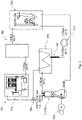
- the CHP system 100 shown consists of a steam generator 110, which is connected via a valve 180 to an inlet of a steam engine 1, 120, which drives a generator 130 to generate electricity.
- a steam generator 110 which is connected via a valve 180 to an inlet of a steam engine 1, 120, which drives a generator 130 to generate electricity.
- oil which, however, mixes with the expanded water vapor during the operation of the steam engine 1, 120 and is discharged with it.
- the expanded steam discharged from the steam engine 1, 120 has a relatively large amount of oil.
- the steam engine 1, 120 is followed by a condenser 150 for condensing the expanded steam, which has a pressure of approximately 0.15 bar and a temperature of approximately 55° C. when it leaves the steam engine 120.
- the condensed water vapor which also contains a large proportion of oil, is fed to a condensate suction pump (or circulation pump) 170, in particular a piston pump, via a water column 190, which increases the pressure of the condensed water vapor to approx. 0.25 bar .sucked in by this one.
- the condensate suction pump increases the pressure of the condensed water vapor or the oil-water mixture that is now present to approximately 1.50 bar and conveys the oil-water mixture to a device 140 for separating oil and water.
- the separated or separated oil is routed back to a crankshaft chamber of the steam engine or injected into the steam engine for fine sealing and the cleaned water is routed to a feed water tank 160, which feeds the treated or cleaned water to the steam generator 110 again for steam generation Provides, so the cycle is closed.
- FIG 2 1 shows a schematic sectional view of a steam engine 1 equipped with a control valve 50 according to an embodiment of the present invention.
- the steam engine 1 shown has a cylinder 10 which has an upper end 11 and a lower end 12 .
- the cylinder 10 is connected to a crankcase 20 at the lower end 12 .
- a plurality of outlet openings 13 are provided in the circumferential direction in the cylinder wall/working space wall 14 of the cylinder 10 .
- the outlet openings 13 connect a cylinder chamber or a working space 15 with an annular chamber 16 in order to discharge or discharge used steam from the working space 15 .
- the outlet openings 13 are arranged close to a bottom dead center UT of a piston 30, which is located at bottom dead center UT in the view shown.
- the piston 30 is translationally movable along a central axis CA of the cylinder 10 between the bottom dead center UT and a top dead center OT.
- the piston 30 is connected to a crankshaft (not shown) housed in the crankcase 20 via a piston connecting rod or piston control rod (not shown).
- the piston 30 has a sealing ring 31 at its lower end 32 and a plurality of sealing rings 31 at its upper end 33 .
- the engine further includes a cylinder head unit 40 .
- the cylinder head unit 40 has a first case body 41 and a second case body 42 . Furthermore, in the first housing body 41 is provided with an antechamber (vapor chamber) 44 which communicates with the working space 15 via an opening 43 .
- the opening can be opened and closed by means of the control valve 50, which has a valve seat 51 and a valve body 52, with which the inflow of live steam (superheated steam that is under high pressure) into the working chamber can be controlled.
- the control valve 50 is in the closed state, ie the valve body 52 is pressed against the valve seat 51 in order to prevent the flow of live steam into the working chamber 15 .
- the valve body 52 is guided in translation along the central axis CA by means of an axial guide 55 and is subjected to a force or pressed against the valve seat 51 by an elastic element 54, which is implemented by a compression spring in the illustrated embodiment. Furthermore, the second housing body 42 contains fluid channels, not shown, with which the valve body 52 can be acted upon on its side facing away from the valve seat 51 with the working fluid, i.e. the superheated steam, in order to increase the closing force between the valve seat 51 and the valve body 52 and thus a tight Complete the opening 43 to ensure.
- the working fluid i.e. the superheated steam
- valve body 52 has, on an end facing valve seat 51, a surface 52A that is beveled inward toward a central axis of valve seat 51 or toward central axis CA, as a result of which the surface of valve body 52 facing valve seat 51 is funnel-shaped. In this way it is possible to realize a defined annular contact surface between the valve seat 51 and the valve body 52 .
- FIG figure 3 shows an enlarged partial view of the schematic sectional view of FIG figure 2 , to the training of Control valve, in particular the valve seat 51 and the valve body 52 further to clarify.
- the valve seat 51 is formed of a simple valve seat disk which is inserted into the first housing body 41. This makes it possible to easily replace the valve seat 41 after a long period of use and the associated wear. In this case, the valve seat 51 can be repaired for reuse by simply grinding it again.
- the inwardly tapered surface 52A forms with the plane defined by the contact area between valve body 52 and valve seat 51 and in which figure 3 is oriented horizontally, an inclination angle ⁇ , which is actually extremely flat, in a range of 0.5 ° to 1.5 °. However, to better illustrate the invention, the angle is shown much larger.
- the valve body 52 has a projection 52B which is provided on the slanted surface 52A facing the valve seat 51 and projects into the opening 43. As shown in FIG.
- the projection 52B makes it possible for the piston 30 to move the valve body 52 against the applied steam pressure and against the applied spring force of the Valve seat 52 is lifted and thus the opening 43 is released, whereby live steam can flow from the antechamber 44 into the working chamber 15 and thus the piston 30 can cause a downward movement from top dead center OT to bottom dead center UT.
- the projection (valve drive 53) of the piston 30 has a spherical or curved surface/shape, whereby between the projection 52B of the valve body 52 and the projection of the Piston 30 a point contact point is realized and thus only forces in the axial direction, ie along the central axis CA, can be transmitted from the piston 30 to the valve body 52, but no transverse forces can be introduced into the valve body 52.
Description
Die vorliegende Offenbarung betrifft ein Steuerventil für einen Dampfmotor, zum Beispiel einen Dampfmotor der mechanische Arbeit unter Verwendung von Dampf als sein Arbeitsfluid verrichtet. Genauer betrifft die vorliegende Offenbarung ein Steuerventil für einen Kolbendampfmotor, der bevorzugt in der Erzeugung elektrischen Stroms Anwendung findet. Des Weiteren betrifft die vorliegende Offenbarung einen das vorher genannte Steuerventil aufweisenden Dampfmotor sowie eine den Dampfmotor aufweisende Kraft-Wärme-Kopplungsanlage.The present disclosure relates to a control valve for a steam engine, for example a steam engine that performs mechanical work using steam as its working fluid. More specifically, the present disclosure relates to a control valve for a reciprocating steam engine, preferably having application in electric power generation. Furthermore, the present disclosure relates to a steam engine having the aforementioned control valve and a combined heat and power plant having the steam engine.
Dezentrale Kraft-Wärme-Kopplungsanlagen (KWK-Anlagen) haben sich bereits seit längerer Zeit als vorteilhafte Alternative zur herkömmlichen Kombination von lokaler Heizung und zentralem Stromkraftwerk etabliert. KWK-Anlagen werden zur Gewinnung von elektrischer Energie und der Gewinnung von Nutzwärme genutzt, insbesondere werden KWK-Anlagen vorzugweise am Ort oder in der Nähe der Nutzwärmesenke betrieben. Als Antrieb für den Stromerzeuger können zum Beispiel Verbrennungsmotoren, wie Diesel- oder Ottomotoren, Stirlingmotoren, Dampfmotoren, Brennkraftturbinen oder Dampfmaschinen verwendet werden.Decentralized combined heat and power plants (CHP plants) have long been established as an advantageous alternative to the conventional combination of local heating and central power plant. CHP plants are used to generate electrical energy and to generate useful heat, in particular CHP plants are preferably operated on site or in the vicinity of the useful heat sink. Combustion engines such as diesel or Otto engines, Stirling engines, steam engines, internal combustion turbines or steam engines can be used, for example, to drive the power generator.
Hinsichtlich KWK-Anlagen hat in jüngster Zeit insbesondere die Verwendung von Dampfmotoren an Interesse gewonnen. Dies liegt vorrangig an dem erzielbaren hohen Gesamtwirkungsgrad bei gleichzeitig geringem Schadstoffausstoß und der fast freien Wahl des flüssigen oder festen Brennstoffs, wie beispielsweise Holz, Pellets, Biogas, oder Biomasse. Der hohe Wirkungsgrad kann durch Dampfdrücke von 40 bar bis 150 bar und Dampftemperaturen von ca. 300 bis 600 °C erzielt werden. Dampfmotoren finden aufgrund der genannten Vorteile auch Anwendung in kleineren Anlagen zur Biomasseverstromung, Abwärmeverstromungsanlagen, Abfallverbrennungsanlagen und thermischen Nachverbrennungsanlagen.With regard to CHP systems, the use of steam engines in particular has recently gained interest. This is primarily due to the achievable high overall efficiency with low pollutant emissions and the almost free choice of liquid or solid fuel, such as wood, pellets, biogas or biomass. The high level of efficiency can be achieved with steam pressures of 40 bar to 150 bar and steam temperatures of approx. 300 to 600 °C. Due to the advantages mentioned, steam engines are also used in smaller plants for biomass power generation, waste heat power generation plants, waste incineration plants and thermal post-combustion plants.
Bekannte Dampfmotoren, wie beispielsweise der in
Um den Dampfmotor, insbesondere den Kolben des Dampfmotors mit einer ausreichenden Dampfmenge, welche unter einem entsprechend hohem Druck steht, effizient betreiben zu können, ist es notwendig, den unter Druck stehenden Dampf/Frischdampf in einer sehr kurzen Zeit und mit präzisem Timing einem Arbeitsraum des Dampfmotors zuzuführen, um den Arbeitszyklus des Kolbens ohne Störungen (mit Rundlauf) betreiben zu können. Hierzu ist ein Steuerventil notwendig, um die Fluidströmung des Frischdampfs zu dem Arbeitsraum des Dampfmotors optimal steuern beziehungsweise regeln zu können.In order to be able to efficiently operate the steam engine, in particular the piston of the steam engine, with a sufficient amount of steam, which is under a correspondingly high pressure, it is necessary to deliver the pressurized steam/live steam to a working space of the steam engine in a very short time and with precise timing To supply the steam engine in order to be able to operate the working cycle of the piston without disturbances (with concentricity). A control valve is necessary for this in order to be able to optimally control or regulate the fluid flow of the live steam to the working chamber of the steam engine.
Solche Ventile zur Steuerung und/oder Regelung einer Fluidströmung umfassen in der Regel einen Ventilsitz und ein Ventilglied, das axial beweglich gelagert ist. Das Ventilglied weist üblicherweise einen Ventilschaft und an einem Ende davon einen Ventilkörper auf. Zur Betätigung des Ventils, d.h. zur axialen Bewegung des Ventilglieds, insbesondere des Ventilkörpers, ist ferner ein Ventiltrieb vorgesehen, der unmittelbar oder mittelbar kraftübertragend mit dem Ventilschaft verbunden ist. Dadurch kann der Ventilkörper zum Öffnen des Ventils von dem Ventilsitz abgehoben und ein Durchfluss durch die Rohrleitung bzw. das Ventil ermöglicht werden. Um das Ventil in eine geschlossene Stellung zu bringen wird der Ventilkörper wieder in Kontakt mit dem Ventilsitz gebracht und sperrt somit eine Fluidströmung durch die Rohrleitung.Such valves for controlling and/or regulating a fluid flow generally include a valve seat and a valve member that is mounted so that it can move axially. The valve member typically includes a valve stem and a valve body at one end thereof. To actuate the valve, i.e. to move the valve member, in particular the valve body, axially, a valve drive is also provided, which is directly or indirectly connected to the valve stem in a force-transmitting manner. As a result, the valve body can be lifted off the valve seat to open the valve and flow through the pipeline or the valve can be made possible. To place the valve in a closed position, the valve body is brought back into contact with the valve seat, thus blocking fluid flow through the tubing.
Durch die oben beschriebenen hohen Temperaturen beim Betrieb eines Dampfmotors treten thermische Veränderungen, insbesondere Materialausdehnungen, auf, welche zur Veränderung des Betriebspunkts des Ventils führen können. Dadurch kann es vorkommen, dass das Ventilglied, insbesondere der Ventilkörper mit einer zu großen Kraft in den Ventilsitz gedrückt wird. Bei einer wiederholten Betätigung des Ventils hat dies jedoch einen hohen Verschleiß des Ventilkörpers und/oder des Ventilsitzes zur Folge, der zu einer Leckage des Ventils im geschlossenen Zustand führen kann. Zudem kann der Verschleiß Bypassströme im Ventil und Störungen im Gesamtsystem, in dem das Ventil zur Steuerung und/oder Regelung eines Fluidstroms eingesetzt wird, zur Folge haben. Ferner kann es auch vorkommen, dass herkömmliche Ventile aufgrund von Materialausdehnungen nicht vollständig schließen und folglich eine Leckage auftritt.Due to the high temperatures described above when operating a steam engine, thermal changes, in particular material expansion, occur, which can lead to a change in the operating point of the valve. As a result, it can happen that the valve member, in particular the valve body, is pressed into the valve seat with too great a force. However, repeated actuation of the valve results in high wear of the valve body and/or the valve seat, which can lead to leakage of the valve in the closed state. In addition, he can Wear bypass flows in the valve and malfunctions in the overall system in which the valve is used to control and / or regulate a fluid flow result. Furthermore, it can also happen that conventional valves do not close completely due to material expansion and consequently a leak occurs.
Im Stand der Technik sind bisher Ventile zur Steuerung beziehungsweise Regelung einer Fluidströmung bekannt, die mittels eines kegelförmigen Ventilsitzes ein vereinfachtes Zusammenwirken des Ventilkörpers und des Ventilsitzes ermöglichen sollen. Insbesondere wird dadurch der Ventilkörper in den Ventilsitz geführt, was auch bei hohen Kräften zu einem sicheren und verschleißarmen Schließen führen soll. Dennoch liefern auch diese Ventile bei hohen Temperaturen und Drücken kein zufriedenstellendes Ergebnis.Valves for controlling or regulating a fluid flow are known in the prior art, which are intended to enable simplified interaction of the valve body and the valve seat by means of a conical valve seat. In particular, this guides the valve body into the valve seat, which should lead to reliable and low-wear closing even with high forces. Nevertheless, even these valves do not provide a satisfactory result at high temperatures and pressures.
Weitere verwandte Techniken sind in der
Der Erfindung liegt die Aufgabe zu Grunde, ein Steuerventil zur Steuerung und/oder Regelung einer Dampfströmung, in einem Dampfmotor bereitzustellen, das in der Lage ist, trotz der im Arbeitszyklus eines Dampfmotors vorliegenden hohen Temperaturen und Drücke ein zuverlässiges und dauerhaftes Schließen bzw. Absperren des Ventils zu gewährleisten, während eine einfache Herstellung sowie leichte Instandhaltung realisiert werden.The object of the invention is to provide a control valve for controlling and/or regulating a steam flow in a steam engine, which is capable of reliably and permanently closing or shutting off the steam engine, despite the high temperatures and pressures present in the working cycle of a steam engine to ensure the valve while realizing ease of manufacture and easy maintenance.
Diese Aufgabe wird gelöst durch ein Steuerventil nach Anspruch 1, einen das Steuerventil aufweisenden Dampfmotor nach Anspruch 10 sowie eine den Dampfmotor aufweisende Kraft-Wärme-Kopplungsanlage nach Anspruch 14. Bevorzugte Weiterbildungen der Erfindung sind in den abhängigen Ansprüchen gegeben, wobei der Gegenstand der das Steuerventil betreffenden Ansprüche im Rahmen des Dampfmotors zu Einsatz kommen kann und umgekehrt.This object is achieved by a control valve according to claim 1, a steam engine having the control valve according to
Hierbei ist einer der Grundgedanken der vorliegenden Offenbarung, eine definierte Kontaktfläche, insbesondere eine ringförmige Kontaktfläche zwischen dem Ventilkörper und dem Ventilsitz zu schaffen, mit der trotz der im Arbeitszyklus eines Dampfmotors vorliegenden hohen Temperaturen und Drücke ein zuverlässiges und dauerhaftes Schließen bzw. Absperren des Ventils gewährleistet werden kann, während eine einfache Herstellung sowie leichte Instandhaltung realisiert werden.One of the basic ideas of the present disclosure is to create a defined contact surface, in particular an annular contact surface between the valve body and the valve seat, with which a reliable and permanent closing or shutting off of the valve is ensured despite the high temperatures and pressures present in the working cycle of a steam engine can be performed while realizing ease of manufacture and maintenance.
Wird bei der vorliegenden Anmeldung von hohen Temperaturen gesprochen, so gilt dies insbesondere für einen Dampfstrom, d. h. Temperaturen jenseits der 100°C. Für den effizienten Betrieb eines Dampfmotors sind darüber hinaus Betriebsparameter mit einem Fluiddruck (Dampfdruck) von wie oben bereits angeführt 40 bis 150 bar und Fluidtemperaturen (Dampftemperaturen) von über 500°C nicht unüblich. Bei derartigen Betriebsparametern, ist mit einer hohen thermischen Beanspruchung sämtlicher Bauteile, insbesondere hohen thermischen Spannungen, zu rechnen. Ferner ist bei Dampfmotoren aufgrund der geringeren Molekülgröße (H2O) des Wasserdampfs im Vergleich zu den Verbrennungsgasen (CO2) beim Verbrennungsmotor eine sichere Abdichtung schwieriger zu realisieren.When high temperatures are mentioned in the present application, this applies in particular to a stream of steam, ie temperatures above 100.degree. In addition, operating parameters with a fluid pressure (steam pressure) of 40 to 150 bar, as already mentioned above, and fluid temperatures (steam temperatures) of over 500° C. are not unusual for the efficient operation of a steam engine. With such operating parameters, a high thermal stress on all components, in particular high thermal stresses, is to be expected. Furthermore, a secure seal is more difficult to achieve in steam engines due to the smaller molecular size (H 2 O) of the water vapor compared to the combustion gases (CO 2 ) in the internal combustion engine.
Um dennoch ein dichtes Verschließen des Steuerventils zu ermöglichen, ist es notwendig, äußert große Schließkräfte des Steuerventils zu realisieren, was nur durch eine entsprechend kleine Kontaktfläche zwischen Ventilkörper und Ventilsitz und dementsprechend hoher Flächenpressung realisierbar ist. Dies führt jedoch zu hohen Anforderungen an die Güte der Kontaktflächen der beiden Schließelementen sowie zu hohem Verschleiß.In order to still enable a tight closure of the control valve, it is necessary to realize extremely high closing forces of the control valve, which can only be achieved by a correspondingly small contact surface between the valve body and the valve seat and a correspondingly high surface pressure. However, this leads to high demands on the quality of the contact surfaces of the two closing elements and to high wear.
Um den oben geschilderten Anforderungen gerecht zu werden, stellt die vorliegende Offenbarung ein Steuerventil bereit, bei dem eine leicht definierbare und herstellbare Ringfläche zwischen einem konischen Bauteil und einem flachen Bauteil realisiert wird.In order to meet the needs outlined above, the present disclosure provides a control valve in which an easily definable and manufacturable annular surface is realized between a conical component and a flat component.
Gemäß einem Aspekt der Offenbarung weist ein Steuerventil zur Steuerung und/oder Regelung einer Dampfströmung, in einem Dampfmotor, auf: einen Ventilsitz, einen Ventilkörper, der entlang einer Zentralachse CA des Steuerventils translatorisch geführt ist und bevorzugt mittels eines elastischen Elements gegen den Ventilsitz kraftbeaufschlagt ist, wobei ein dem Ventilsitz zugewandtes axiales Ende des Ventilkörpers eine zur Mittelachse des Ventilkörpers hin abgeschrägte Oberfläche aufweist, wodurch eine ringförmige Kontaktfläche mit dem Ventilsitz ausgebildet ist, oder ein dem Ventilkörper zugewandtes axiales Ende des Ventilsitzes eine zur Mittelachse des Ventilsitzes hin abgeschrägte Oberfläche aufweist, wodurch eine ringförmige Kontaktfläche mit dem Ventilkörper ausgebildet ist.According to one aspect of the disclosure, a control valve for controlling and/or regulating a steam flow in a steam engine has: a valve seat, a valve body, which is guided in translation along a central axis CA of the control valve and is preferably subjected to a force against the valve seat by means of an elastic element , with a the valve seat axial end of the valve body facing toward the central axis of the valve body has a surface tapered toward the center axis of the valve body, thereby forming an annular contact surface with the valve seat, or an axial end of the valve seat facing the valve body has a surface tapered toward the central axis of the valve seat, thereby forming an annular contact surface with the Valve body is formed.
Der Begriff "axial" kann hierbei als entlang der Hauptachse des Ventilglieds oder des Ventiltriebs oder entlang der Zentralachse des Steuerventils selbst verstanden werden und entspricht der Längsrichtung der besagten Elemente.The term "axial" can be understood here as along the main axis of the valve member or the valve train or along the central axis of the control valve itself and corresponds to the longitudinal direction of said elements.
Gemäß einem weiteren Aspekt der vorliegenden Offenbarung ist eine abgeschrägte Oberfläche des Ventilsitzes oder die des Ventilkörpers zur Mittelachse hin nach innen abgeschrägt, wodurch die ringförmige Kontaktfläche im Bereich des Außenumfangs der abgeschrägten Oberfläche ausgebildet ist, wobei die Mittelachse des Ventilsitzes und/oder die Mittelachse des Ventilkörpers parallel zur Zentralachse CA verläuft, insbesondere mit dieser in etwa fluchtet. Hierbei kann der Begriff ʺnach innen" so verstanden werden, dass die Oberfläche in Richtung des Materials des jeweiligen Elements, z.B. des Ventilkörpers hin abgeschrägt ist, womit in der Mitte des Ventilkörpers eine Vertiefung gebildet ist. Mit anderen Worten wird die Oberfläche des Ventilkörpers, die dem Ventilsitz zugewandt ist, trichterförmig, weist also eine konische Form auf.According to another aspect of the present disclosure, a slanted surface of the valve seat or that of the valve body is slanted inward toward the central axis, whereby the annular contact surface is formed in the region of the outer circumference of the slanted surface, the central axis of the valve seat and/or the central axis of the valve body runs parallel to the central axis CA, in particular approximately aligned with it. The term "inwards" can be understood in such a way that the surface is beveled in the direction of the material of the respective element, e.g. the valve body, which forms a depression in the middle of the valve body. In other words, the surface of the valve body, the facing the valve seat, funnel-shaped, ie has a conical shape.
Des Weiteren ist es vorteilhaft, wenn ein Neigungswinkel α der abgeschrägten Oberfläche des Ventilsitzes oder des Ventilkörpers zu einer Ebene, die durch die Kontaktfläche zwischen Ventilkörper und Ventilsitz definiert ist und senkrecht zur Zentralachse verläuft, zwischen 0,5° und 1,5°, bevorzugt 1°, beträgt.Furthermore, it is advantageous if an angle of inclination α of the slanted surface of the valve seat or of the valve body to a plane that is defined by the contact surface between the valve body and the valve seat and runs perpendicular to the central axis is between 0.5° and 1.5° 1°, is.
Auf diese Weise wird eine in Radialrichtung gesehene sehr dünne ringförmige Kontaktfläche zwischen Ventilsitz und Ventilkörper gebildet, welcher ferner leicht herstellbar ist.In this way, seen in the radial direction, a very thin annular contact surface is formed between the valve seat and the valve body, which is also easy to manufacture.
Ferner ist die auf diese Weise hergestellte konische Oberfläche und die damit verbundene Kontaktfläche nach einer gegebenenfalls durchgeführten Wärmebehandlung, insbesondere Härten, leicht wieder auf Maß bringbar, was zum Beispiel durch Schleifen erzielt werden kann. Ebenfalls ist die auf diese Art erzeugte Kontaktfläche nach längerem Gebrauch und damit verbundenem Verschleiß durch Schleifen einfach wieder in Stand zusetzen.Furthermore, the conical surface produced in this way and the contact surface connected thereto can easily be brought back to size after an optional heat treatment, in particular hardening, which can be achieved, for example, by grinding. The contact surface created in this way can also be easily repaired by grinding after a long period of use and the associated wear and tear.
Ferner ist es bevorzugt, dass der Ventilsitz durch eine Ventilsitzscheibe ausgebildet ist, die zumindest im Bereich der Kontaktfläche mit dem Ventilkörper eine ebene Fläche aufweist, die bevorzugt senkrecht zur Zentralachse CA ausgerichtet ist.Furthermore, it is preferred that the valve seat is formed by a valve seat disk, which has a flat surface, at least in the region of the contact surface with the valve body, which is preferably aligned perpendicularly to the central axis CA.
Die Ausbildung des Ventilsitzes aus Ventilsitzscheibe bringt ebenfalls die Vorteile mit sich, dass sie einfach herstellbar und wieder in Stand setzbar ist. Ferner kann auf diese Weise der Ventilsitz auf einfache Weise ausgetauscht werden.The formation of the valve seat from a valve seat disc also brings with it the advantage that it is easy to produce and to repair. Furthermore, the valve seat can be easily replaced in this way.
Des Weiteren ist es vorteilhaft, dass der Ventilkörper auf dem dem Ventilsitz zugewandten axialen Ende einen Vorsprung aufweist, der dazu eingerichtet ist, mit einem Ventiltrieb kraftübertragend zusammenzuwirken, um den Ventilkörper von dem Ventilsitz abzuheben und dadurch das Steuerventil zu öffnen, wobei der Ventiltrieb und der Ventilkörper bevorzugt entkoppelt ausgebildet sind.Furthermore, it is advantageous that the valve body has a projection on the axial end facing the valve seat, which is set up to interact with a valve drive in a force-transmitting manner in order to lift the valve body from the valve seat and thereby open the control valve, the valve drive and the Valve body are preferably formed decoupled.
Unter einer Entkopplung ist hierbei zu verstehen, dass sich der Ventiltrieb und der Ventilkörper relativ zueinander und unabhängig voneinander bewegen können.A decoupling is to be understood here as meaning that the valve train and the valve body can move relative to one another and independently of one another.
Ferner ist es bevorzugt, dass der Ventilkörper aus einem zähen Material, beispielsweise HSS-Stahl (Schnellarbeitsstahl bzw. hochligierter Werkzeugstahl) hergestellt ist, der bevorzugt eine Bruchdehnung von mindestens 5%, weiter bevorzugt von mindestens 10%, aufweist. Dabei ist es ferner vorteilhaft, wenn zumindest eine der Kontaktflächen plattiert ist. Bei den Kontaktflächen handelt es sich um die Oberseite des Ventilkörpers, welche mit dem elastischen Element in Kontakt kommt, um die Unterseite des Ventilkörpers, welche mit dem Ventiltrieb in Kontakt kommt, und um die Kontaktfläche mit dem Ventilsitz.It is also preferred that the valve body is made of a tough material, for example HSS steel (high-speed steel or high-alloy tool steel), which preferably has an elongation at break of at least 5%, more preferably at least 10%. It is also advantageous if at least one of the contact surfaces is plated. The contact surfaces are the upper surface of the valve body which comes into contact with the elastic element, the lower surface of the valve body which comes into contact with the valve train, and the contact surface with the valve seat.
Hierbei ist es vorteilhaft, wenn das Plattieren anhand eines Auftragschweißverfahrens wie beispielsweise dem Plasma-Pulver-Auftragschweißen auch PTA-Verfahren genannt durchgeführt wird. Aus Beschichtungsmaterial kann beispielsweise Nickelmartensit, Wolframkarbid oder Stellite bzw. eine Cobalt-Chrom-Hartlegierung verwendet werden. Nach dem Plattieren werden die somit mit einer Verschleißschutzbeschichtung versehenen Kontaktflächen bevorzugt geschliffen.It is advantageous here if the plating is carried out using a build-up welding process such as, for example, plasma powder build-up welding, also known as the PTA process. For example, nickel martensite, tungsten carbide or stellite or a cobalt-chromium hard alloy can be used as the coating material. After plating, the contact surfaces, which are thus provided with an anti-wear coating, are preferably ground.
Alternativ besteht auch die Möglichkeit, auf einen aus beispielsweise HSS-Stahl hergestellten Grundkörper des Ventilkörpers einen Verschleißring aufzuschrumpfen, der beispielsweise aus Nickelmartensit, Wolframkarbid, Stellite bzw. einer Cobalt-Chrom-Hartlegierung oder einem Verbund aus Keramik und Metall hergestellt ist. Der aufgeschrumpfte Ring kann dann mit der oben beschriebenen abgeschrägten Oberfläche versehen werden, um die ringförmige Kontaktfläche zwischen Ventilsitz und Ventilkörper auszubilden.Alternatively, there is also the possibility of shrinking a wear ring made of nickel martensite, tungsten carbide, stellite or a cobalt-chromium hard alloy or a composite of ceramic and metal onto a base body of the valve body made of HSS steel, for example. The shrunk-on ring can then be provided with the beveled surface described above to form the annular contact surface between valve seat and valve body.
Der Ventilsitz bzw. die Ventilsitzscheibe ist bevorzugt aus einem sehr harten verschleißfesten Material hergestellt, das stoßfest ist. Auf einen zähen Kern kann hierbei verzichtet werden, da keine Biegespannung (Bruchbeanspruchung) anliegt. Der Ventilsitz bzw. die Ventilsitzscheibe kann ebenfalls aus einem Verbund aus Keramik und Metall hergestellt werden.The valve seat or valve seat disc is preferably made of a very hard, wear-resistant material that is impact-resistant. There is no need for a tough core, as there is no bending stress (fracture stress). The valve seat or the valve seat disc can also be made from a composite of ceramic and metal.
Ferner ist es bevorzugt, wenn die Ventilsitzscheibe einen Innendurchmesser aufweist, der zumindest so groß ist, dass der Vorsprung des Ventilkörpers und/oder der Ventiltrieb in axialer Richtung, d.h. in Richtung der Zentralachse CA, zumindest teilweise in die Innenbohrung der Ventilsitzscheibe hineinreichen/hineinstehen, bevorzugt durch diese hindurchreichen/hindurchstehen, kann/können.Furthermore, it is preferred if the valve seat disc has an inner diameter that is at least large enough for the projection of the valve body and/or the valve drive to extend/protrude at least partially into the inner bore of the valve seat disc in the axial direction, i.e. in the direction of the central axis CA. preferably reach/stand through them, can/can.
Gemäß einem weiteren Aspekt der vorliegenden Offenbarung, ist der Ventilkörper durch Dampfdruck gegen den Ventilsitz kraftbeaufschlagt, und das elastische Element fungiert lediglich als Dämpfer. Hierbei ist die Federkraft des elastischen Elements, welche den Ventilkörper gegen den Ventilsitz drückt, so eingestellt, dass das Ventil erst ab einer bestimmten Kraftbeaufschlagung durch den Ventiltrieb öffnet, wodurch ein zu frühes Öffnen des Ventils vermieden werden kann. Es kann somit ein gezieltes Öffnen des Ventils erzielt werden.According to a further aspect of the present disclosure, the valve body is biased against the valve seat by steam pressure and the elastic member functions only as a damper. Here, the spring force of the elastic element, which presses the valve body against the valve seat, is adjusted so that the valve only opens when a certain force is applied by the valve drive, which means that the valve can be prevented from opening too early. A targeted opening of the valve can thus be achieved.
Durch beaufschlagen des Ventilkörpers mit Dampfdruck, insbesondere mit Druck des Arbeitsfluids, dem zugeführten Frischdampf, kann eine ausreichend hohe Kraftbeaufschlagung des Ventilkörpers gegen den Ventilsitz gewährleistet werden. Ferner reguliert sich auf diese Weise die Schließkraft des Steuerventils selbstständig bzw. automatisch. Mit anderen Worten, in dem Fall, dass der Dampfmotor unter höhend Drücken (Dampfdrücken) und damit höherer Leistung betrieben wird, steigen die notwendigen Schließkräfte des Steuerventils, anhand deren eine ausreichende Dichtheit/Abdichtung des Steuerventils gewährleistet werden kann, an. Da jedoch der Dampfdruck des Arbeitsfluids direkt verwendet wird, um die notwendige Schließkraft des Steuerventils bereitzustellen, steigt mit höherem Arbeitsdruck auch die zur Verfügung stehende Schließkraft an.By subjecting the valve body to steam pressure, in particular to the pressure of the working fluid, the supplied live steam, a sufficiently high force application of the valve body against the valve seat can be ensured. Furthermore, the closing force of the control valve regulates itself in this way independently or automatically. In other words, if the steam engine is operated under increasing pressures (steam pressures) and thus higher power, the necessary closing forces of the control valve, which can be used to ensure adequate tightness/sealing of the control valve, increase. However, since the vapor pressure of the working fluid is used directly to provide the necessary closing force of the control valve, the available closing force also increases with higher working pressure.
Unter dem Begriff "Frischdampf" ist in der vorliegenden Offenbarung ein Dampf/Heißdampf zu verstehen, der beispielsweise von einem Dampferzeuger einem Dampfmotor zum betrieb des Dampfmotors zugeführt wird. Der Frischdampf weißt hierbei in der Regel Drücke im Bereich von 40 bis 140 bar und Temperaturen über 500°C auf.The term "live steam" is to be understood in the present disclosure as steam/superheated steam which for example, from a steam generator to a steam engine for operating the steam engine. The live steam usually has pressures in the range from 40 to 140 bar and temperatures above 500°C.
Des Weiteren ist es bevorzugt, wenn zumindest die Kontaktfläche des Ventilsitzes und/oder des Ventilkörpers gehärtet ist, und bevorzugt die Härte des Ventilkörpers größer als die Härte des Ventilsitzes ist. Auf diese Weise kann eine ausreichend hohe Härte/Festigkeit der Kontaktfläche sichergestellt werden, die notwendig ist, um der hohen Flächenpressung standhalten zu können.Furthermore, it is preferred if at least the contact surface of the valve seat and/or the valve body is hardened, and preferably the hardness of the valve body is greater than the hardness of the valve seat. In this way, a sufficiently high hardness/strength of the contact surface can be ensured, which is necessary to be able to withstand the high surface pressure.
Gemäß einem weiteren Aspekt der vorliegenden Offenbarung weist die ringförmige Kontaktfläche zwischen Ventilkörper und Ventilsitz eine Ringbreite von 0,2 mm bis 3 mm, bevorzugt 0,5 mm bis 2 mm, weiter bevorzugt 1 mm, auf.According to a further aspect of the present disclosure, the annular contact surface between the valve body and the valve seat has an annular width of 0.2 mm to 3 mm, preferably 0.5 mm to 2 mm, more preferably 1 mm.
Ferner betrifft die vorliegende Offenbarung einen Dampfmotor, insbesondere Kolbendampfmotor der bevorzugt für die Erzeugung elektrischen Stroms verwendet wird, aufweisend: mindestens einen Zylinder, der einen Arbeitsraum umschließt, einen im Arbeitsraum zwischen einem oberen Totpunkt OT und einem unteren Totpunkt UT entlang einer Zentralachse CA des Zylinders hin und her beweglichen Kolben, und das oben beschriebene Steuerventil, wobei das Steuerventil zur Steuerung und/oder Regelung einer Fluidströmung, insbesondere einer Dampfströmung, die als Arbeitsfluid(strömung) des Dampfmotors fungiert, dient.Furthermore, the present disclosure relates to a steam engine, in particular a piston steam engine, which is preferably used for generating electric power, having: at least one cylinder which encloses a working space, one in the working space between a top dead center OT and a bottom dead center UT along a central axis CA of the cylinder reciprocating piston, and the control valve described above, wherein the control valve serves to control and/or regulate a fluid flow, in particular a steam flow, which acts as the working fluid (flow) of the steam engine.
Des Weiteren ist es bevorzugt, dass der Ventiltrieb des Steuerventils als Vorsprung des Kolbens ausgebildet ist, der an einem oberen Ende des Kolbens, das dem Steuerventil zugewandt ist, angeordnet ist, wobei der Vorsprung den Ventilkörper von dem Ventilsitz abhebt, wenn sich der Kolben in dem Bereich / in der Nähe des oberen Totpunkts befindet, um das Steuerventil zu öffnen.Furthermore, it is preferred that the valve drive of the control valve is designed as a projection of the piston, which is arranged on an upper end of the piston that faces the control valve, the projection lifting the valve body from the valve seat when the piston moves in the area / near the top dead center to open the control valve.
Auf diese Weise ist es ermöglicht, auf einen zusätzlichen Ventiltrieb wie beispielsweis ein Piezoelement bzw. einen Piezoantrieb zu verzichten. Ferner können auf diese Weise kurze Öffnungs- und Schließzeiten erreicht werden, ohne eine extrem hohe Beanspruchung der Ventiltriebkomponenten in Kauf nehmen zu müssen. Dies liegt insbesondere daran, dass die Öffnungs- und Schließkräfte des Steuerventils einerseits durch die Fluidströmung zur Verfügung gestellt werden und andererseits durch den Kolben, insbesondere den Vorsprung des Kolbens eingeleitet werden. Entsprechend werden die Öffnungskräfte von der Pleuelstange und deren Lagerung aufgenommen, welche aufgrund des hohen Drehmoments des Dampfmotors sehr robust ausgelegt sind.This makes it possible to dispense with an additional valve drive, such as a piezo element or a piezo drive. In addition, short opening and closing times can be achieved in this way without having to accept extremely high stress on the valve train components. This is due in particular to the fact that the opening and closing forces of the control valve are made available on the one hand by the fluid flow and on the other hand are introduced by the piston, in particular the projection of the piston. Accordingly, the opening forces are absorbed by the connecting rod and its bearing, which are very robust due to the high torque of the steam engine.
Hierbei ist es ferner vorteilhaft, wenn der Vorsprung eine konusförmige Form aufweist, welche insbesondere an der dem Ventilkörper zugewandten Seite eine ebene, insbesondere zur Zentralachse CA senkrecht ausgerichtete, Kontaktfläche aufweist. Auf diese Weise ist es möglich, eine kreisförmige Kontaktfläche zwischen Ventilkörper und Ventiltrieb auszubilden und somit die auftretende Flächenpressung und den damit verbundenen Verschleiß zu reduzieren.It is also advantageous here if the projection has a conical shape, which has a flat contact surface, in particular aligned perpendicularly to the central axis CA, in particular on the side facing the valve body. In this way it is possible to form a circular contact surface between the valve body and the valve train and thus to reduce the surface pressure that occurs and the associated wear.
Des Weiteren ist es vorteilhaft, wenn die Kontaktfläche des Ventiltriebs plattiert ist, insbesondere anhand eines Auftragschweißverfahren wie beispielsweise das Plasma-Pulver-Auftragschweißen auch PTA-Verfahren genannt. Hierbei wird der Kolben an seiner Oberseite mit einer konkaven Aussparung versehen, in welche das Beschichtungsmaterial mittels Auftragsscheißen eingebracht wird und anschließend zu einer ebenen Kontaktfläche geschliffen wird. Aus Beschichtungsmaterial kann beispielsweise Nickelmartensit, Wolframkarbid oder Stellite bzw. eine Cobalt-Chrom-Hartlegierung verwendet werden.Furthermore, it is advantageous if the contact surface of the valve train is plated, in particular using a build-up welding process such as plasma powder build-up welding, also known as the PTA process. In this case, the piston is provided with a concave recess on its upper side, into which the coating material is introduced by means of build-up welding and is then ground to form a flat contact surface. For example, nickel martensite, tungsten carbide or stellite or a cobalt-chromium hard alloy can be used as the coating material.
Ferner ist es vorteilhaft, wenn der Dampfmotor eine Vorkammer aufweist, die von außen mit Frischdampf versorgbar ist, wobei die Vorkammer eine Öffnung zum Einleiten des Frischdampfs in den Arbeitsraum aufweist, und die Öffnung durch das Steuerventil geöffnet und geschlossen werden kann.Furthermore, it is advantageous if the steam engine has an antechamber that can be supplied with fresh steam from the outside, wherein the antechamber has an opening for introducing the live steam into the working space, and the opening can be opened and closed by the control valve.
Gemäß einem weiteren Aspekt ist der Ventilkörper in Form eines zylindrischen Druckstempels ausgebildet, der durch eine Axialführung translatorisch entlang der Zentralachse CA des Steuerventils, welche bevorzugt mit einer Zentralachse CA des Zylinders 10 in etwa fluchtet, beweglich ist, und bevorzugt durch Druck des Frischdampfs, der auf eine dem Ventilsitz abgewandten Seite des Ventilkörpers beaufschlagt ist, gegen den Ventilsitz kraftbeaufschlagt ist.According to a further aspect, the valve body is designed in the form of a cylindrical plunger, which can be moved in translation by an axial guide along the central axis CA of the control valve, which is preferably approximately aligned with a central axis CA of the
Ferner betrifft die vorliegende Offenbarung eine Kraft-Wärme-Kopplungsanlage, die einen Dampferzeuger und den oben beschriebenen Dampfmotor aufweist, wobei der Dampfmotor mit einem Generator zur Erzeugung elektrischen Stroms gekoppelt ist.Furthermore, the present disclosure relates to a combined heat and power plant that has a steam generator and the steam engine described above, wherein the steam engine is coupled to a generator for generating electrical power.
-
Fig. 1 zeigt ein schematisches Diagramm einer Kraft-Wärme-Kopplungsanlage,1 shows a schematic diagram of a combined heat and power plant, -
Fig. 2 zeigt eine schematische Schnittdarstellung eines Dampfmotors gemäß einer Ausführungsform der vorliegenden Erfindung, wobei das Steuerventil in der geschlossenen Position ist und der Kolben sich im unteren Totpunkt befindet, und2 Figure 12 shows a schematic sectional view of a vapor engine according to an embodiment of the present invention, with the control valve in the closed position and the piston at bottom dead center, and -
Fig. 3 zeigt eine vergrößerte Teilansicht der schematischen Schnittdarstellung vonFig. 2 , um die Ausbildung des Steuerventils zu verdeutlichen.3 shows an enlarged partial view of the schematic sectional view of FIG2 , to clarify the design of the control valve.
Nachfolgend werden anhand der beigefügten Figuren bevorzugte Ausführungsformen der vorliegenden Erfindung im Detail beschrieben. Weitere in diesem Zusammenhang genannte Modifikationen bestimmter Merkmale können jeweils einzeln miteinander kombiniert werden, um weitere Ausführungsformen auszubilden.Preferred embodiments of the present invention are described in detail below with reference to the attached figures. Others mentioned in this context Modifications of specific features can each be individually combined with one another to form further embodiments.
Dabei sind in den verschiedenen Figuren gleiche oder entsprechende Elemente jeweils mit den gleichen oder ähnlichen Bezugszeichen bezeichnet.The same or corresponding elements are denoted by the same or similar reference symbols in the various figures.
Dem Dampfmotor 1, 120 ist ein Kondensator 150 zur Kondensation des entspannten Wasserdampfs, welcher einen Druck von ca. 0,15 bar und eine Temperatur von ca. 55°C aufweist, wenn dieser den Dampfmotor 120 verlässt, nachgeschalten.The steam engine 1, 120 is followed by a
Der kondensierte Wasserdampf, welcher weiterhin einen großen Anteil an Öl enthält, wird über eine Wassersäule 190, welche den Druck des kondensierten Wasserdampfs auf ca. 0,25 bar erhöht, einer Kondensat-Absaugpumpe (bzw. Zirkulationspumpe) 170, insbesondere Kolbenpumpe, zugeführt bzw. von dieser angesaugt. Die Kondensat-Absaugpumpe erhöht den Druck des kondensierten Wasserdampfs bzw. des nun vorliegenden Öl-Wassers-Gemischs auf ungefähr 1,50 bar und fördert das Öl-Wasser-Gemisch zu einer Vorrichtung 140 zum Trennen von Öl und Wasser.The condensed water vapor, which also contains a large proportion of oil, is fed to a condensate suction pump (or circulation pump) 170, in particular a piston pump, via a
Wie der
Der Kolben 30 ist translatorisch entlang einer Mittelachse CA des Zylinders 10 zwischen dem unten Totpunkt UT und einem oberen Totpunkt OT beweglich. Der Kolben 30 ist über eine nichtdargestellte Kolbenverbindungsstange oder Kolbensteuerungsstange mit einer nicht gezeigten Kurbelwelle verbunden, die in dem Kurbelgehäuse 20 untergebracht ist. Der Kolben 30 weist an seinem unteren Ende 32 einen Dichtring 31 und an seinem oberen Ende 33 mehrere Dichtringe 31 auf.The
Der Motor umfasst ferner eine Zylinderkopfeinheit 40. Die Zylinderkopfeinheit 40 weist einen ersten Gehäusekörper 41 und einen zweiten Gehäusekörper 42 auf. Ferner ist in dem ersten Gehäusekörper 41 eine Vorkammer (Dampfkammer) 44 vorgesehen, welche über eine Öffnung 43 mit dem Arbeitsraum 15 kommuniziert. Die Öffnung kann mittels des Steuerventils 50, das einen Ventilsitz 51 und einen Ventilkörper 52 aufweist, geöffnet und verschlossen werden, womit das Einströmen von Frischdampf (Heißdampf, der unter Hochdruck steht) in den Arbeitsraum gesteuert werden kann. In
Der Ventilkörper 52 ist mittels einer Axialführung 55 entlang der Zentralachse CA translatorisch geführt und wird durch ein elastisches Element 54, welches in der dargestellten Ausführungsform durch eine Druckfeder realisiert ist, gegen den Ventilsitz 51 kraftbeaufschlagt beziehungsweise gedrückt. Ferner befinden sich im zweiten Gehäusekörper 42 nicht dargestellte Fluidkanäle, mit welchen der Ventilkörper 52 auf seiner dem Ventilsitz 51 abgewandten Seite mit dem Arbeitsfluid, d.h. dem Heißdampf, beaufschlagt werden kann, um die Schließkraft zwischen Ventilsitz 51 und Ventilkörper 52 zu erhöhen und somit ein dichtes Abschließen der Öffnung 43 zu gewährleisten.The
Wie der
Wie in der
Aus der vorhergehenden Beschreibung erkennt der Fachmann, dass verschiedene Modifikationen und Variationen der Vorrichtung und des Verfahrens der Erfindung durchgeführt werden können, ohne den Umfang der Erfindung zu verlassen. Ferner wurde die Erfindung in Bezug auf bestimmte Ausführungsformen beschrieben, die jedoch nur zum besseren Verständnis der Erfindung dienen sollen, und diese nicht einschränken sollen. Der Fachmann erkennt auch sofort, dass viele verschiedene Kombinationen der Elemente zur Ausführung der vorliegenden Erfindung verwendet werden können.From the foregoing description, those skilled in the art will recognize that various modifications and variations can be made in the apparatus and method of the invention without departing from the scope of the invention. Furthermore, the invention has been described with reference to specific embodiments, which are intended only for a better understanding of the invention and are not intended to limit it. Those skilled in the art will also readily recognize that many different combinations of elements can be used to practice the present invention.
Claims (14)
- Control valve (50) for controlling and/or regulating a steam flow in a steam engine (1), comprising:a valve seat (51),a valve body (52) which is guided in a translational manner along a central axis (CA) of the control valve (50) and is force-loaded against the valve seat (51) by means of an elastic element (54),characterised in thatan axial end of the valve body (52) facing the valve seat (51) has a surface (52A) bevelled towards the middle axis of the valve body (52) which forms an annular contact surface with the valve seat (51), oran axial end of the valve seat (51) facing the valve body (52) has a surface (51A) bevelled towards the middle axis of the valve seat (51) which forms an annular contact surface with the valve body (52).
- Control valve (50) according to claim 1, wherein a bevelled surface (51A, 52A) of the valve seat (51) or of the valve body (52) is bevelled inwards towards the middle axis, as a result of which the annular contact surface is formed in the region of the outer circumference of the bevelled surface (51A, 52A), wherein the middle axis of the valve seat (51) and/or the middle axis of the valve body (52) runs parallel to the central axis (CA), in particular being roughly aligned with this.
- Control valve (50) according to claim 1 or 2, wherein an angle of inclination α of the bevelled surface (51A, 52A) of the valve seat (51) or of the valve body (52) relative to a plane defined by the contact surface between valve body (52) and valve seat (51) and perpendicular to the central axis (CA) is between 0.5° and 1.5°, preferably 1°.
- Control valve (50) according to one of the preceding claims, wherein the valve seat (51) is formed by a valve seat washer, preferably having a flat surface, at least in the region of the contact surface with the valve body (52), which is preferably oriented perpendicular to the central axis (CA).
- Control valve (50) according to one of the preceding claims, wherein the valve body (52) has a projection (52B) on the axial end facing the valve seat (51) which is configured to interact in a force-transmitting manner with a valve drive (53) in order to lift the valve body (52) from the valve seat (51) and thereby open the control valve (50), wherein the valve drive (53) and the valve body (22) are preferably decoupled.
- Control valve (50) according to claim 5, which is dependent on claim 4, wherein the valve seat washer has an inner diameter (D1) which is at least so large that the projection (52B) of the valve body (52) and/or the valve drive (53) can reach/extend in the axial direction at least partially into the inner bore of the valve seat, preferably reach/extend through this.
- Control valve (50) according to one of the preceding claims, wherein the valve body (52) is force-loaded against the valve seat (51) by vapour pressure, and the elastic element (54) functions as a damper.
- Control valve (50) according to one of the preceding claims, wherein at least the contact surface of the valve seat (51) and/or the valve body (52) is hardened, and preferably the hardness of the valve body (52) is greater than the hardness of the valve seat (51).
- Control valve (50) according to one of the preceding claims, wherein the annular contact surface has a ring width of 0.2 mm to 3 mm, preferably 0.5 mm to 2 mm, more preferably 1 mm.
- Steam engine (1), in particular a piston steam engine, which is preferably used for the generation of electric current, comprising:at least one cylinder (10) which encloses a working chamber (15),a piston (30) which can move back and forth in the working chamber (15) along a central axis (CA) of the cylinder (10) between an upper dead centre (OT) and a lower dead centre (UT), anda control valve (50) according to one of the preceding claims 1 to 9, wherein the control valve (50) serves to control and/or regulate a steam flow that functions as the working fluid of the steam engine.
- Steam engine (1) according to claim 10, wherein the valve drive (53) of the control valve (50) is formed as a projection of the piston (30) which is arranged on an upper end (33) of the piston facing the control valve (50), wherein the projection lifts the valve body (52) from the valve seat (51) when the piston (30) is located in the region of or near the upper dead centre (OT) in order to open the control valve (50).
- Steam engine (1) according to one of the claims 10 or 11, further comprising:
a prechamber (44) which can be supplied with fresh steam from the outside, wherein the prechamber (44) has an opening (43) for introducing the fresh steam into the working chamber (15), wherein the opening (43) can be opened and closed by the control valve (50). - Steam engine (1) according to one of the claims 10 to 12, wherein the valve body (52) is designed in the form of a cylindrical plunger which is, via an axial guide (55), moveable in a translational manner along the central axis (CA) of the control valve, which preferably aligns roughly with a central axis (CA) of the cylinder (10), and is preferably force-loaded against the valve seat (51) through the pressure of the fresh steam applied to a side of the valve body (52) facing away from the valve seat (51) .
- Combined heat and power plant comprising:a steam generator (110), anda steam engine (1, 120) according to one of the preceding claims 10 to 13, wherein the steam engine is coupled with a generator (130) in order to generate electric current.
Priority Applications (1)
| Application Number | Priority Date | Filing Date | Title |
|---|---|---|---|
| EP19200418.2A EP3798413B1 (en) | 2019-09-30 | 2019-09-30 | Control valve for a steam engine, steam engine comprising said control valve, and combined heat and power plant comprising the steam engine |
Applications Claiming Priority (1)
| Application Number | Priority Date | Filing Date | Title |
|---|---|---|---|
| EP19200418.2A EP3798413B1 (en) | 2019-09-30 | 2019-09-30 | Control valve for a steam engine, steam engine comprising said control valve, and combined heat and power plant comprising the steam engine |
Publications (2)
| Publication Number | Publication Date |
|---|---|
| EP3798413A1 EP3798413A1 (en) | 2021-03-31 |
| EP3798413B1 true EP3798413B1 (en) | 2022-08-10 |
Family
ID=68104429
Family Applications (1)
| Application Number | Title | Priority Date | Filing Date |
|---|---|---|---|
| EP19200418.2A Active EP3798413B1 (en) | 2019-09-30 | 2019-09-30 | Control valve for a steam engine, steam engine comprising said control valve, and combined heat and power plant comprising the steam engine |
Country Status (1)
| Country | Link |
|---|---|
| EP (1) | EP3798413B1 (en) |
Families Citing this family (2)
| Publication number | Priority date | Publication date | Assignee | Title |
|---|---|---|---|---|
| EP4245969B1 (en) | 2022-03-16 | 2024-04-17 | RD Estate GmbH & Co. KG | Steam motor |
| CN115110999A (en) * | 2022-06-24 | 2022-09-27 | 何致远 | Steam engine |
Family Cites Families (7)
| Publication number | Priority date | Publication date | Assignee | Title |
|---|---|---|---|---|
| US1630750A (en) * | 1925-06-15 | 1927-05-31 | Krasno Philip | Internal-combustion-engine valve |
| GB1163211A (en) * | 1967-01-19 | 1969-09-04 | Chadburns Res & Dev Ltd | Improvements in or relating to Apparatus for Dispensing Liquids Incorporating a Reciprocating Pump |
| US4050357A (en) * | 1974-06-25 | 1977-09-27 | Carter Sr J Warne | Steam admission valve and variable clearance volume steam cylinder |
| JPS5999016A (en) * | 1982-11-29 | 1984-06-07 | Komatsu Ltd | Impulse valve for steam engine |
| US4766924A (en) * | 1986-12-08 | 1988-08-30 | The Lee Company | Pressure relief valve |
| DE3913351A1 (en) * | 1989-04-22 | 1990-10-25 | Teves Gmbh Alfred | DEVICE FOR AUXILIARY PRINTING |
| EP3271557B1 (en) | 2015-03-16 | 2020-11-25 | RD Estate GmbH & Co. KG | Steam engine |
-
2019
- 2019-09-30 EP EP19200418.2A patent/EP3798413B1/en active Active
Also Published As
| Publication number | Publication date |
|---|---|
| EP3798413A1 (en) | 2021-03-31 |
Similar Documents
| Publication | Publication Date | Title |
|---|---|---|
| EP1778968B1 (en) | Device for the injection of fuel into the combustion chamber of an internal combustion engine | |
| EP2394049B1 (en) | Fuel injection valve for internal combustion engines | |
| EP0546985A1 (en) | Fuel injection valve for a reciprocating internal combustion engine optionally operating on diesel oil or on a gaseous fuel | |
| EP3798413B1 (en) | Control valve for a steam engine, steam engine comprising said control valve, and combined heat and power plant comprising the steam engine | |
| DE10054022A1 (en) | Method for operating a heat engine | |
| EP0908617A1 (en) | Fuel injection apparatus | |
| EP3169889A1 (en) | Dual-fuel fuel injector | |
| DE102011055871A1 (en) | A fuel supply pump and method of making a housing therefor | |
| EP3128137B1 (en) | Assembly for controlling a flow of working steam with high pressure | |
| WO2017121427A1 (en) | Method for operating an axial piston motor, and axial piston motor | |
| DE4136223C1 (en) | ||
| AT512422B1 (en) | DEVICE FOR INJECTING FUEL IN THE COMBUSTION ENGINE OF AN INTERNAL COMBUSTION ENGINE | |
| EP4001709A1 (en) | Spring-free control valve for a piston steam engine, a piston steam engine comprising said control valve, a force heat coupling system comprising the piston steam engine and a method for operating the piston steam engine | |
| EP4001587A1 (en) | Control valve with optimized flow for a piston steam engine comprising said control valve, a force heat coupling system comprising the piston steam engine and a method for operating the piston steam engine | |
| EP4001586A1 (en) | Control valve with optimized thermal stress, a piston steam engine comprising said control valve, a force heat coupling system comprising the piston steam engine and a method for operating the piston steam engine | |
| EP1483499B1 (en) | Installation for the pressure-modulated formation of the injection behavior | |
| WO2015014476A1 (en) | Dual-fuel fuel injector | |
| EP4245969B1 (en) | Steam motor | |
| EP1763629A1 (en) | Fuel injection device | |
| EP3798412B1 (en) | Steam engine and combined heat and power plant comprising the steam engine | |
| EP1978230B1 (en) | Thermal energy device, in particular for using low temperature heat sources | |
| DE102008060063A1 (en) | internal combustion engine | |
| EP1320677B1 (en) | Valve arrangement | |
| EP2410140B1 (en) | lubrication device for a piston | |
| EP1546545B1 (en) | Pump/nozzle unit and method for setting the hardness of contact areas of a control valve |
Legal Events
| Date | Code | Title | Description |
|---|---|---|---|
| PUAI | Public reference made under article 153(3) epc to a published international application that has entered the european phase |
Free format text: ORIGINAL CODE: 0009012 |
|
| STAA | Information on the status of an ep patent application or granted ep patent |
Free format text: STATUS: THE APPLICATION HAS BEEN PUBLISHED |
|
| AK | Designated contracting states |
Kind code of ref document: A1 Designated state(s): AL AT BE BG CH CY CZ DE DK EE ES FI FR GB GR HR HU IE IS IT LI LT LU LV MC MK MT NL NO PL PT RO RS SE SI SK SM TR |
|
| STAA | Information on the status of an ep patent application or granted ep patent |
Free format text: STATUS: REQUEST FOR EXAMINATION WAS MADE |
|
| 17P | Request for examination filed |
Effective date: 20210917 |
|
| RBV | Designated contracting states (corrected) |
Designated state(s): AL AT BE BG CH CY CZ DE DK EE ES FI FR GB GR HR HU IE IS IT LI LT LU LV MC MK MT NL NO PL PT RO RS SE SI SK SM TR |
|
| STAA | Information on the status of an ep patent application or granted ep patent |
Free format text: STATUS: EXAMINATION IS IN PROGRESS |
|
| 17Q | First examination report despatched |
Effective date: 20211215 |
|
| GRAP | Despatch of communication of intention to grant a patent |
Free format text: ORIGINAL CODE: EPIDOSNIGR1 |
|
| STAA | Information on the status of an ep patent application or granted ep patent |
Free format text: STATUS: GRANT OF PATENT IS INTENDED |
|
| INTG | Intention to grant announced |
Effective date: 20220525 |
|
| GRAS | Grant fee paid |
Free format text: ORIGINAL CODE: EPIDOSNIGR3 |
|
| GRAA | (expected) grant |
Free format text: ORIGINAL CODE: 0009210 |
|
| STAA | Information on the status of an ep patent application or granted ep patent |
Free format text: STATUS: THE PATENT HAS BEEN GRANTED |
|
| AK | Designated contracting states |
Kind code of ref document: B1 Designated state(s): AL AT BE BG CH CY CZ DE DK EE ES FI FR GB GR HR HU IE IS IT LI LT LU LV MC MK MT NL NO PL PT RO RS SE SI SK SM TR |
|
| REG | Reference to a national code |
Ref country code: AT Ref legal event code: REF Ref document number: 1510683 Country of ref document: AT Kind code of ref document: T Effective date: 20220815 Ref country code: CH Ref legal event code: EP |
|
| REG | Reference to a national code |
Ref country code: IE Ref legal event code: FG4D Free format text: LANGUAGE OF EP DOCUMENT: GERMAN |
|
| REG | Reference to a national code |
Ref country code: DE Ref legal event code: R096 Ref document number: 502019005222 Country of ref document: DE |
|
| REG | Reference to a national code |
Ref country code: NL Ref legal event code: MP Effective date: 20220810 |
|
| REG | Reference to a national code |
Ref country code: LT Ref legal event code: MG9D |
|
| PG25 | Lapsed in a contracting state [announced via postgrant information from national office to epo] |
Ref country code: SE Free format text: LAPSE BECAUSE OF FAILURE TO SUBMIT A TRANSLATION OF THE DESCRIPTION OR TO PAY THE FEE WITHIN THE PRESCRIBED TIME-LIMIT Effective date: 20220810 Ref country code: RS Free format text: LAPSE BECAUSE OF FAILURE TO SUBMIT A TRANSLATION OF THE DESCRIPTION OR TO PAY THE FEE WITHIN THE PRESCRIBED TIME-LIMIT Effective date: 20220810 Ref country code: PT Free format text: LAPSE BECAUSE OF FAILURE TO SUBMIT A TRANSLATION OF THE DESCRIPTION OR TO PAY THE FEE WITHIN THE PRESCRIBED TIME-LIMIT Effective date: 20221212 Ref country code: NO Free format text: LAPSE BECAUSE OF FAILURE TO SUBMIT A TRANSLATION OF THE DESCRIPTION OR TO PAY THE FEE WITHIN THE PRESCRIBED TIME-LIMIT Effective date: 20221110 Ref country code: NL Free format text: LAPSE BECAUSE OF FAILURE TO SUBMIT A TRANSLATION OF THE DESCRIPTION OR TO PAY THE FEE WITHIN THE PRESCRIBED TIME-LIMIT Effective date: 20220810 Ref country code: LV Free format text: LAPSE BECAUSE OF FAILURE TO SUBMIT A TRANSLATION OF THE DESCRIPTION OR TO PAY THE FEE WITHIN THE PRESCRIBED TIME-LIMIT Effective date: 20220810 Ref country code: LT Free format text: LAPSE BECAUSE OF FAILURE TO SUBMIT A TRANSLATION OF THE DESCRIPTION OR TO PAY THE FEE WITHIN THE PRESCRIBED TIME-LIMIT Effective date: 20220810 Ref country code: FI Free format text: LAPSE BECAUSE OF FAILURE TO SUBMIT A TRANSLATION OF THE DESCRIPTION OR TO PAY THE FEE WITHIN THE PRESCRIBED TIME-LIMIT Effective date: 20220810 |
|
| PG25 | Lapsed in a contracting state [announced via postgrant information from national office to epo] |
Ref country code: PL Free format text: LAPSE BECAUSE OF FAILURE TO SUBMIT A TRANSLATION OF THE DESCRIPTION OR TO PAY THE FEE WITHIN THE PRESCRIBED TIME-LIMIT Effective date: 20220810 Ref country code: IS Free format text: LAPSE BECAUSE OF FAILURE TO SUBMIT A TRANSLATION OF THE DESCRIPTION OR TO PAY THE FEE WITHIN THE PRESCRIBED TIME-LIMIT Effective date: 20221210 Ref country code: HR Free format text: LAPSE BECAUSE OF FAILURE TO SUBMIT A TRANSLATION OF THE DESCRIPTION OR TO PAY THE FEE WITHIN THE PRESCRIBED TIME-LIMIT Effective date: 20220810 Ref country code: GR Free format text: LAPSE BECAUSE OF FAILURE TO SUBMIT A TRANSLATION OF THE DESCRIPTION OR TO PAY THE FEE WITHIN THE PRESCRIBED TIME-LIMIT Effective date: 20221111 |
|
| PG25 | Lapsed in a contracting state [announced via postgrant information from national office to epo] |
Ref country code: SM Free format text: LAPSE BECAUSE OF FAILURE TO SUBMIT A TRANSLATION OF THE DESCRIPTION OR TO PAY THE FEE WITHIN THE PRESCRIBED TIME-LIMIT Effective date: 20220810 Ref country code: RO Free format text: LAPSE BECAUSE OF FAILURE TO SUBMIT A TRANSLATION OF THE DESCRIPTION OR TO PAY THE FEE WITHIN THE PRESCRIBED TIME-LIMIT Effective date: 20220810 Ref country code: ES Free format text: LAPSE BECAUSE OF FAILURE TO SUBMIT A TRANSLATION OF THE DESCRIPTION OR TO PAY THE FEE WITHIN THE PRESCRIBED TIME-LIMIT Effective date: 20220810 Ref country code: DK Free format text: LAPSE BECAUSE OF FAILURE TO SUBMIT A TRANSLATION OF THE DESCRIPTION OR TO PAY THE FEE WITHIN THE PRESCRIBED TIME-LIMIT Effective date: 20220810 Ref country code: CZ Free format text: LAPSE BECAUSE OF FAILURE TO SUBMIT A TRANSLATION OF THE DESCRIPTION OR TO PAY THE FEE WITHIN THE PRESCRIBED TIME-LIMIT Effective date: 20220810 |
|
| REG | Reference to a national code |
Ref country code: DE Ref legal event code: R097 Ref document number: 502019005222 Country of ref document: DE |
|
| REG | Reference to a national code |
Ref country code: BE Ref legal event code: MM Effective date: 20220930 |
|
| PG25 | Lapsed in a contracting state [announced via postgrant information from national office to epo] |
Ref country code: SK Free format text: LAPSE BECAUSE OF FAILURE TO SUBMIT A TRANSLATION OF THE DESCRIPTION OR TO PAY THE FEE WITHIN THE PRESCRIBED TIME-LIMIT Effective date: 20220810 Ref country code: MC Free format text: LAPSE BECAUSE OF FAILURE TO SUBMIT A TRANSLATION OF THE DESCRIPTION OR TO PAY THE FEE WITHIN THE PRESCRIBED TIME-LIMIT Effective date: 20220810 Ref country code: EE Free format text: LAPSE BECAUSE OF FAILURE TO SUBMIT A TRANSLATION OF THE DESCRIPTION OR TO PAY THE FEE WITHIN THE PRESCRIBED TIME-LIMIT Effective date: 20220810 |
|
| PLBE | No opposition filed within time limit |
Free format text: ORIGINAL CODE: 0009261 |
|
| STAA | Information on the status of an ep patent application or granted ep patent |
Free format text: STATUS: NO OPPOSITION FILED WITHIN TIME LIMIT |
|
| PG25 | Lapsed in a contracting state [announced via postgrant information from national office to epo] |
Ref country code: LU Free format text: LAPSE BECAUSE OF NON-PAYMENT OF DUE FEES Effective date: 20220930 Ref country code: AL Free format text: LAPSE BECAUSE OF FAILURE TO SUBMIT A TRANSLATION OF THE DESCRIPTION OR TO PAY THE FEE WITHIN THE PRESCRIBED TIME-LIMIT Effective date: 20220810 |
|
| 26N | No opposition filed |
Effective date: 20230511 |
|
| PG25 | Lapsed in a contracting state [announced via postgrant information from national office to epo] |
Ref country code: IE Free format text: LAPSE BECAUSE OF NON-PAYMENT OF DUE FEES Effective date: 20220930 |
|
| PG25 | Lapsed in a contracting state [announced via postgrant information from national office to epo] |
Ref country code: SI Free format text: LAPSE BECAUSE OF FAILURE TO SUBMIT A TRANSLATION OF THE DESCRIPTION OR TO PAY THE FEE WITHIN THE PRESCRIBED TIME-LIMIT Effective date: 20220810 |
|
| PG25 | Lapsed in a contracting state [announced via postgrant information from national office to epo] |
Ref country code: BE Free format text: LAPSE BECAUSE OF NON-PAYMENT OF DUE FEES Effective date: 20220930 |
|
| PGFP | Annual fee paid to national office [announced via postgrant information from national office to epo] |
Ref country code: IT Payment date: 20230925 Year of fee payment: 5 |
|
| PGFP | Annual fee paid to national office [announced via postgrant information from national office to epo] |
Ref country code: FR Payment date: 20230911 Year of fee payment: 5 Ref country code: DE Payment date: 20230925 Year of fee payment: 5 |
|
| PGFP | Annual fee paid to national office [announced via postgrant information from national office to epo] |
Ref country code: CH Payment date: 20231001 Year of fee payment: 5 |