EP3798158B1 - Modular treatment device for containers - Google Patents
Modular treatment device for containers Download PDFInfo
- Publication number
- EP3798158B1 EP3798158B1 EP20192281.2A EP20192281A EP3798158B1 EP 3798158 B1 EP3798158 B1 EP 3798158B1 EP 20192281 A EP20192281 A EP 20192281A EP 3798158 B1 EP3798158 B1 EP 3798158B1
- Authority
- EP
- European Patent Office
- Prior art keywords
- containers
- transport
- treatment
- coating
- intended
- Prior art date
- Legal status (The legal status is an assumption and is not a legal conclusion. Google has not performed a legal analysis and makes no representation as to the accuracy of the status listed.)
- Active
Links
- 230000032258 transport Effects 0.000 claims description 156
- 238000000576 coating method Methods 0.000 claims description 44
- 239000011248 coating agent Substances 0.000 claims description 42
- 239000012526 feed medium Substances 0.000 claims 2
- 238000012546 transfer Methods 0.000 description 22
- 238000000034 method Methods 0.000 description 10
- 239000007789 gas Substances 0.000 description 7
- 230000001954 sterilising effect Effects 0.000 description 5
- 239000000126 substance Substances 0.000 description 4
- 238000004659 sterilization and disinfection Methods 0.000 description 3
- XKRFYHLGVUSROY-UHFFFAOYSA-N Argon Chemical compound [Ar] XKRFYHLGVUSROY-UHFFFAOYSA-N 0.000 description 2
- 238000013461 design Methods 0.000 description 2
- 230000009969 flowable effect Effects 0.000 description 2
- 238000004519 manufacturing process Methods 0.000 description 2
- 238000004806 packaging method and process Methods 0.000 description 2
- 238000000623 plasma-assisted chemical vapour deposition Methods 0.000 description 2
- 230000000717 retained effect Effects 0.000 description 2
- VYPSYNLAJGMNEJ-UHFFFAOYSA-N Silicium dioxide Chemical compound O=[Si]=O VYPSYNLAJGMNEJ-UHFFFAOYSA-N 0.000 description 1
- XUIMIQQOPSSXEZ-UHFFFAOYSA-N Silicon Chemical compound [Si] XUIMIQQOPSSXEZ-UHFFFAOYSA-N 0.000 description 1
- HSFWRNGVRCDJHI-UHFFFAOYSA-N alpha-acetylene Natural products C#C HSFWRNGVRCDJHI-UHFFFAOYSA-N 0.000 description 1
- 229910052786 argon Inorganic materials 0.000 description 1
- QVGXLLKOCUKJST-UHFFFAOYSA-N atomic oxygen Chemical compound [O] QVGXLLKOCUKJST-UHFFFAOYSA-N 0.000 description 1
- 238000010276 construction Methods 0.000 description 1
- 238000000151 deposition Methods 0.000 description 1
- 230000008021 deposition Effects 0.000 description 1
- 238000011161 development Methods 0.000 description 1
- 230000018109 developmental process Effects 0.000 description 1
- 125000002534 ethynyl group Chemical group [H]C#C* 0.000 description 1
- 239000011521 glass Substances 0.000 description 1
- 238000012423 maintenance Methods 0.000 description 1
- 239000000203 mixture Substances 0.000 description 1
- 239000001301 oxygen Substances 0.000 description 1
- 229910052760 oxygen Inorganic materials 0.000 description 1
- 239000002243 precursor Substances 0.000 description 1
- 238000012545 processing Methods 0.000 description 1
- 229910052710 silicon Inorganic materials 0.000 description 1
- 239000010703 silicon Substances 0.000 description 1
- 229910052814 silicon oxide Inorganic materials 0.000 description 1
- 238000005406 washing Methods 0.000 description 1
- XLYOFNOQVPJJNP-UHFFFAOYSA-N water Chemical compound O XLYOFNOQVPJJNP-UHFFFAOYSA-N 0.000 description 1
Images


Classifications
-
- B—PERFORMING OPERATIONS; TRANSPORTING
- B67—OPENING, CLOSING OR CLEANING BOTTLES, JARS OR SIMILAR CONTAINERS; LIQUID HANDLING
- B67C—CLEANING, FILLING WITH LIQUIDS OR SEMILIQUIDS, OR EMPTYING, OF BOTTLES, JARS, CANS, CASKS, BARRELS, OR SIMILAR CONTAINERS, NOT OTHERWISE PROVIDED FOR; FUNNELS
- B67C3/00—Bottling liquids or semiliquids; Filling jars or cans with liquids or semiliquids using bottling or like apparatus; Filling casks or barrels with liquids or semiliquids
- B67C3/02—Bottling liquids or semiliquids; Filling jars or cans with liquids or semiliquids using bottling or like apparatus
- B67C3/22—Details
-
- B—PERFORMING OPERATIONS; TRANSPORTING
- B65—CONVEYING; PACKING; STORING; HANDLING THIN OR FILAMENTARY MATERIAL
- B65B—MACHINES, APPARATUS OR DEVICES FOR, OR METHODS OF, PACKAGING ARTICLES OR MATERIALS; UNPACKING
- B65B59/00—Arrangements to enable machines to handle articles of different sizes, to produce packages of different sizes, to vary the contents of packages, to handle different types of packaging material, or to give access for cleaning or maintenance purposes
- B65B59/04—Machines constructed with readily-detachable units or assemblies, e.g. to facilitate maintenance
-
- B—PERFORMING OPERATIONS; TRANSPORTING
- B05—SPRAYING OR ATOMISING IN GENERAL; APPLYING FLUENT MATERIALS TO SURFACES, IN GENERAL
- B05C—APPARATUS FOR APPLYING FLUENT MATERIALS TO SURFACES, IN GENERAL
- B05C13/00—Means for manipulating or holding work, e.g. for separate articles
- B05C13/02—Means for manipulating or holding work, e.g. for separate articles for particular articles
-
- B—PERFORMING OPERATIONS; TRANSPORTING
- B41—PRINTING; LINING MACHINES; TYPEWRITERS; STAMPS
- B41J—TYPEWRITERS; SELECTIVE PRINTING MECHANISMS, i.e. MECHANISMS PRINTING OTHERWISE THAN FROM A FORME; CORRECTION OF TYPOGRAPHICAL ERRORS
- B41J3/00—Typewriters or selective printing or marking mechanisms characterised by the purpose for which they are constructed
- B41J3/407—Typewriters or selective printing or marking mechanisms characterised by the purpose for which they are constructed for marking on special material
- B41J3/4073—Printing on three-dimensional objects not being in sheet or web form, e.g. spherical or cubic objects
- B41J3/40733—Printing on cylindrical or rotationally symmetrical objects, e. g. on bottles
-
- B—PERFORMING OPERATIONS; TRANSPORTING
- B65—CONVEYING; PACKING; STORING; HANDLING THIN OR FILAMENTARY MATERIAL
- B65B—MACHINES, APPARATUS OR DEVICES FOR, OR METHODS OF, PACKAGING ARTICLES OR MATERIALS; UNPACKING
- B65B55/00—Preserving, protecting or purifying packages or package contents in association with packaging
- B65B55/02—Sterilising, e.g. of complete packages
-
- B—PERFORMING OPERATIONS; TRANSPORTING
- B67—OPENING, CLOSING OR CLEANING BOTTLES, JARS OR SIMILAR CONTAINERS; LIQUID HANDLING
- B67C—CLEANING, FILLING WITH LIQUIDS OR SEMILIQUIDS, OR EMPTYING, OF BOTTLES, JARS, CANS, CASKS, BARRELS, OR SIMILAR CONTAINERS, NOT OTHERWISE PROVIDED FOR; FUNNELS
- B67C7/00—Concurrent cleaning, filling, and closing of bottles; Processes or devices for at least two of these operations
- B67C7/0006—Conveying; Synchronising
-
- B—PERFORMING OPERATIONS; TRANSPORTING
- B05—SPRAYING OR ATOMISING IN GENERAL; APPLYING FLUENT MATERIALS TO SURFACES, IN GENERAL
- B05D—PROCESSES FOR APPLYING FLUENT MATERIALS TO SURFACES, IN GENERAL
- B05D7/00—Processes, other than flocking, specially adapted for applying liquids or other fluent materials to particular surfaces or for applying particular liquids or other fluent materials
- B05D7/22—Processes, other than flocking, specially adapted for applying liquids or other fluent materials to particular surfaces or for applying particular liquids or other fluent materials to internal surfaces, e.g. of tubes
- B05D7/227—Processes, other than flocking, specially adapted for applying liquids or other fluent materials to particular surfaces or for applying particular liquids or other fluent materials to internal surfaces, e.g. of tubes of containers, cans or the like
-
- B—PERFORMING OPERATIONS; TRANSPORTING
- B65—CONVEYING; PACKING; STORING; HANDLING THIN OR FILAMENTARY MATERIAL
- B65G—TRANSPORT OR STORAGE DEVICES, e.g. CONVEYORS FOR LOADING OR TIPPING, SHOP CONVEYOR SYSTEMS OR PNEUMATIC TUBE CONVEYORS
- B65G2201/00—Indexing codes relating to handling devices, e.g. conveyors, characterised by the type of product or load being conveyed or handled
- B65G2201/02—Articles
- B65G2201/0235—Containers
- B65G2201/0244—Bottles
-
- B—PERFORMING OPERATIONS; TRANSPORTING
- B65—CONVEYING; PACKING; STORING; HANDLING THIN OR FILAMENTARY MATERIAL
- B65G—TRANSPORT OR STORAGE DEVICES, e.g. CONVEYORS FOR LOADING OR TIPPING, SHOP CONVEYOR SYSTEMS OR PNEUMATIC TUBE CONVEYORS
- B65G2207/00—Indexing codes relating to constructional details, configuration and additional features of a handling device, e.g. Conveyors
- B65G2207/30—Modular constructions
-
- B—PERFORMING OPERATIONS; TRANSPORTING
- B65—CONVEYING; PACKING; STORING; HANDLING THIN OR FILAMENTARY MATERIAL
- B65G—TRANSPORT OR STORAGE DEVICES, e.g. CONVEYORS FOR LOADING OR TIPPING, SHOP CONVEYOR SYSTEMS OR PNEUMATIC TUBE CONVEYORS
- B65G37/00—Combinations of mechanical conveyors of the same kind, or of different kinds, of interest apart from their application in particular machines or use in particular manufacturing processes
- B65G37/02—Flow-sheets for conveyor combinations in warehouses, magazines or workshops
-
- B—PERFORMING OPERATIONS; TRANSPORTING
- B65—CONVEYING; PACKING; STORING; HANDLING THIN OR FILAMENTARY MATERIAL
- B65G—TRANSPORT OR STORAGE DEVICES, e.g. CONVEYORS FOR LOADING OR TIPPING, SHOP CONVEYOR SYSTEMS OR PNEUMATIC TUBE CONVEYORS
- B65G47/00—Article or material-handling devices associated with conveyors; Methods employing such devices
- B65G47/74—Feeding, transfer, or discharging devices of particular kinds or types
- B65G47/84—Star-shaped wheels or devices having endless travelling belts or chains, the wheels or devices being equipped with article-engaging elements
- B65G47/841—Devices having endless travelling belts or chains equipped with article-engaging elements
- B65G47/842—Devices having endless travelling belts or chains equipped with article-engaging elements the article-engaging elements being grippers
-
- B—PERFORMING OPERATIONS; TRANSPORTING
- B65—CONVEYING; PACKING; STORING; HANDLING THIN OR FILAMENTARY MATERIAL
- B65G—TRANSPORT OR STORAGE DEVICES, e.g. CONVEYORS FOR LOADING OR TIPPING, SHOP CONVEYOR SYSTEMS OR PNEUMATIC TUBE CONVEYORS
- B65G54/00—Non-mechanical conveyors not otherwise provided for
- B65G54/02—Non-mechanical conveyors not otherwise provided for electrostatic, electric, or magnetic
-
- C—CHEMISTRY; METALLURGY
- C23—COATING METALLIC MATERIAL; COATING MATERIAL WITH METALLIC MATERIAL; CHEMICAL SURFACE TREATMENT; DIFFUSION TREATMENT OF METALLIC MATERIAL; COATING BY VACUUM EVAPORATION, BY SPUTTERING, BY ION IMPLANTATION OR BY CHEMICAL VAPOUR DEPOSITION, IN GENERAL; INHIBITING CORROSION OF METALLIC MATERIAL OR INCRUSTATION IN GENERAL
- C23C—COATING METALLIC MATERIAL; COATING MATERIAL WITH METALLIC MATERIAL; SURFACE TREATMENT OF METALLIC MATERIAL BY DIFFUSION INTO THE SURFACE, BY CHEMICAL CONVERSION OR SUBSTITUTION; COATING BY VACUUM EVAPORATION, BY SPUTTERING, BY ION IMPLANTATION OR BY CHEMICAL VAPOUR DEPOSITION, IN GENERAL
- C23C16/00—Chemical coating by decomposition of gaseous compounds, without leaving reaction products of surface material in the coating, i.e. chemical vapour deposition [CVD] processes
- C23C16/04—Coating on selected surface areas, e.g. using masks
- C23C16/045—Coating cavities or hollow spaces, e.g. interior of tubes; Infiltration of porous substrates
-
- C—CHEMISTRY; METALLURGY
- C23—COATING METALLIC MATERIAL; COATING MATERIAL WITH METALLIC MATERIAL; CHEMICAL SURFACE TREATMENT; DIFFUSION TREATMENT OF METALLIC MATERIAL; COATING BY VACUUM EVAPORATION, BY SPUTTERING, BY ION IMPLANTATION OR BY CHEMICAL VAPOUR DEPOSITION, IN GENERAL; INHIBITING CORROSION OF METALLIC MATERIAL OR INCRUSTATION IN GENERAL
- C23C—COATING METALLIC MATERIAL; COATING MATERIAL WITH METALLIC MATERIAL; SURFACE TREATMENT OF METALLIC MATERIAL BY DIFFUSION INTO THE SURFACE, BY CHEMICAL CONVERSION OR SUBSTITUTION; COATING BY VACUUM EVAPORATION, BY SPUTTERING, BY ION IMPLANTATION OR BY CHEMICAL VAPOUR DEPOSITION, IN GENERAL
- C23C16/00—Chemical coating by decomposition of gaseous compounds, without leaving reaction products of surface material in the coating, i.e. chemical vapour deposition [CVD] processes
- C23C16/44—Chemical coating by decomposition of gaseous compounds, without leaving reaction products of surface material in the coating, i.e. chemical vapour deposition [CVD] processes characterised by the method of coating
- C23C16/54—Apparatus specially adapted for continuous coating
Definitions
- the present invention relates to a device and a method for treating containers.
- the present invention is described with reference to the coating of plastic containers, in particular the coating of the inner wall of plastic containers.
- the invention described here is also applicable to other different types of container handling, such as sterilization devices.
- preferred embodiments of the invention result in advantages that are particularly applicable to coating devices.
- a coating device is known from the prior art, which has a feed star and a carrier wheel on which a large number of coating stations are arranged, which transport and coat the containers at the same time. These devices have certain disadvantages. On the one hand, maintenance of individual coating stations is not possible without stopping the entire system.
- the US 9,873,569 B1 describes a machine for treating containers, whereby treatment modules can be removed from their operating positions so that the machine can be adapted to different treatment processes or expanded in terms of throughput
- a packaging machine with several work stations is known, the packaging machine being constructed from several modules that are detachably coupled to one another.
- a transport device which transports containers from the first container treatment device to the second container treatment device, and has at least one transport element movably mounted on the transport path.
- the EP 1 787 662 A1 further describes a modular washing and sterilization system
- the present invention is therefore based on the object of proposing a device and a method which, in particular, also enable variable expandability of such systems. This is achieved according to the invention by the subject matter of claim 1. Advantageous embodiments and further developments are the subject of the subclaims.
- a device for treating containers and in particular plastic containers has a container treatment unit, wherein the device has a main transport device which is suitable and intended for transporting the containers along a predetermined transport path, and wherein the first container treatment unit has at least one treatment device and preferably at least two treatment devices which are suitable and intended to treat the containers in a specified manner.
- the device has a supply and discharge unit which is suitable and intended to supply containers to be treated to at least the first container treatment unit and to discharge containers treated by the first container treatment unit.
- the device has a media supply unit which is suitable and intended to supply media to the at least first treatment device and/or to remove a medium, such as air in particular, from the first treatment device.
- the device has a modular structure and can preferably be expanded and/or changed as desired and at least one further container treatment device can be added, which treats the containers in the predetermined manner and which preferably has a transport device which is suitable and intended to transport the containers along a predetermined transport path transport, as well as at least two treatment stations, which are suitable and intended to treat the containers in a predetermined manner.
- a device according to the invention for coating containers and in particular plastic containers has a container treatment unit, the device having a main transport device which is suitable and intended to transport the containers along a predetermined transport path, the container treatment unit having at least two coating devices for coating walls of the containers which are suitable and intended to coat the containers in a predetermined manner.
- the device further has a supply and discharge unit, which is suitable and intended to supply containers to be treated to at least the first treatment unit and to remove containers treated by the first treatment unit, and with a media supply unit which is suitable and intended for this purpose, to the at least one first To supply media to the treatment unit
- the device has a modular structure and/or can be expanded as desired, such that at least one further container coating device can be added, which has a treatment transport device which is suitable and intended to transport the containers along a predetermined transtransport path at least two coating modules which are suitable and intended to coat the containers in the specified manner.
- the system has a modular structure and/or can be expanded as desired and can be supplemented by further treatment devices in order, for example, to increase the capacity.
- the term device for treating containers is used for the entire system.
- This device has a treatment unit, which in turn can have one or more treatment devices.
- the treatment facilities in turn have at least one and preferably a large number of treatment stations.
- these treatment devices also preferably each have a transport device, which preferably feeds the containers to the individual treatment stations.
- the main transport device is preferably adaptable with regard to at least one property, in particular in order to adapt the device to different numbers of treatment devices.
- the holding capacity of the main transport device can be adjusted with regard to the containers and/or a transport length of the main transport device.
- the main transport device is constructed like a segment and in this way can be adapted in particular to a different number of treatment devices.
- first container treatment device and the second container treatment device are similar devices which carry out essentially the same treatment processes, such as coating processes.
- the supply and discharge unit on the one hand and the media supply unit on the other hand are retained.
- the media are, for example, chemicals with which the plastic containers are supplied.
- the medium can also be “a negative pressure”, that is, in this case the media supply unit supplies the containers with a negative pressure or air is removed from the containers.
- media is therefore understood to mean substances in particular, but not electrical energy.
- the treatment devices themselves can optionally be coupled to the main transport device in order to be able to change the production output of the system.
- the main transport device transports the containers continuously.
- the supply and removal unit feeds the containers, in particular, to the main transport device.
- the treatment unit is spatially arranged between the supply unit and the media supply unit. In this way, a particularly efficient system layout can be achieved.
- a front side can be provided which has a display device and in particular a touch panel.
- the feed and discharge unit can, for example, have one or two or even more transport stars, which serve to feed the containers to the main transport device.
- the supply and discharge unit is also suitable and intended to supply containers to be treated to the further treatment device and to remove containers treated by the further treatment device. This means that the supply and discharge unit also serves to supply the other treatment facility.
- the media supply unit is intended to supply media to the further treatment device, whereby, as mentioned above, the medium can also be understood as applying a vacuum, that is, in the physical sense, the removal of a medium - namely air.
- the media supply unit is suitable and intended to supply multiple and/or different media to the treatment devices.
- the container treatment devices are connected in series and/or parallel with respect to the transport path of the containers. This means that several such treatment devices can be arranged one behind the other along the transport path of the containers. In the case of parallel transport, a transport path can be split into two sub-paths.
- the treatment device has a treatment transport device which transports the containers and the containers can be transferred from the main transport device to one of the treatment devices for the purpose of treatment by the treatment device, and the containers can be returned to the containers in particular after they have been treated by the treatment device Main transport facility can be transferred.
- This container transport device can be, for example, a movable and/or rotatable carrier.
- the treatment transport device is suitable and intended to transport the containers in a clocked manner.
- individual treatment stations of the treatment unit are designed to be stationary. This means that the treatment process, for example a coating process, is particularly preferably carried out in a stationary state of the containers (with respect to the transport path).
- the main transport device is particularly suitable and intended to transport the containers continuously.
- the treatment device can have at least three, preferably at least four, treatment stations.
- the treatment device preferably has at most 20, preferably at most 18, preferably at most 16, preferably at most 14 and preferably at most 10 treatment stations.
- the treatment devices are selected from a group of treatment devices, which include coating devices according to the invention for coating walls for containers, printing devices for printing on the containers, sterilizing devices for sterilizing containers, filling devices for filling containers, closing devices for closing containers and the like contains.
- the containers are in particular plastic containers, but the coating of glass containers would also be conceivable.
- the device has a container turning device which is suitable and intended for turning the containers to be transported.
- a container turning device which is suitable and intended for turning the containers to be transported.
- the containers it is possible for the containers to be fed to the feed and discharge device with their mouths facing upwards, but the actual treatment process takes place in a turned state of the containers, that is, a state in which the mouth of the containers protrudes downwards (i.e means closer to the center of the earth).
- said container turning device is a component of the feed and discharge unit. This means that when the system is expanded, this turning device is retained and preferably not modified. However, it is also possible that the container turning device is not part of the feed and discharge unit, but merely feeds the containers to it.
- the turning device can also be designed as a means of circulation and transport, such as a rotating chain.
- This can preferably also be arranged horizontally and thus enable the containers to be turned.
- the turning device prefferably has a linear motor drive device and in particular a long stator, which is particularly preferably also arranged horizontally. It would be possible for a chain or such a long stator to be designed, for example, oval, and to run spatially, for example, like a vehicle chain, for example a tank chain. In this way, the containers can be turned over in a particularly simple manner.
- the device has a pitch changing device which is suitable and intended for changing a distance between two containers arranged one behind the other in the transport device.
- This pitch changing device can also be a component of the feed and discharge unit mentioned above.
- At least one treatment device and/or treatment station and preferably all treatment devices and/or the treatment stations are arranged perpendicularly with respect to a transport path of the containers.
- this treatment unit is arranged above or below the transport path of the containers.
- at least one treatment element can move essentially vertically with respect to the transport path of the containers. This can, for example, be an element which can be inserted into these containers through an opening of the containers.
- a coating module can be arranged at a right angle to the transfer path mentioned.
- the treatment devices in the form of coating devices each have (gas) lances that can be inserted into the containers.
- the treatment devices also have ignition devices such as, in particular, ignition electrodes.
- a gas lance and at least one ignition electrode preferably form an independent unit.
- media feeds are also provided in order to feed coating media to the gas lance.
- the treatment device therefore preferably has an elongated, rod-shaped element, in particular a lance.
- This lance preferably has openings.
- a flowable medium can preferably be introduced into the containers through these openings.
- This flowable medium is preferably a gas suitable for the plasma process.
- PECVD plasma enhanced chemical vapor deposition
- other gases are also conceivable, for example acetylene for the deposition of so-called DLC layers.
- argon and water vapor can be introduced into the containers.
- the coating device or the coating modules have vacuum pumps.
- drives are also provided that move a lance into the containers.
- vacuum pumps, drives for coating lances and pumps for the coating gas can preferably be switched off.
- At least one transport device and in particular the main transport device transports the containers at least in sections along a transport path that deviates from a circular segment-shaped course or has a deviating circular segment-shaped course. While transport wheels are usually used in the prior art, it is proposed here that the transport path has a different curvature. For example, the transport path can have straight sections or curved sections.
- This transport path can preferably be designed in the form of an oval, that is to say with two straight sections and two deflection areas.
- At least one transport device has a rotating means of transport and in particular a transport chain or a long stator.
- This means of transport is particularly preferably aligned horizontally.
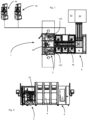
- FIG. 1 shows a representation to illustrate the invention.
- the reference number 1 refers to the device in its entirety.
- This has a feed and discharge unit 2 for the containers.
- This feed and discharge unit can have a first transport device 122, in particular a first transport star 122, and a second transport device 123, in particular a second transport star 123.
- the containers are fed to the device by means of the first transport star and the containers (possibly already treated) are removed by means of the second transport device 123.
- the reference number 42 indicates a main transport device, which on the one hand takes over the containers from a transport star 122 and in turn delivers them to a transport star 123.
- This main transport device also projects into the supply and discharge unit 2 and extends into a container treatment unit 4. The containers can be removed from this main transport device 42 for the purpose of their treatment by the individual treatment devices.
- the main transport device 42 has a large number of holding elements which are used to hold the individual containers and to transport them.
- the containers are preferably transported in a row.
- the feed star 122 and the discharge star 123 also have a large number of holding devices in order to transport the containers individually.
- one or both transport devices 122, 123 can be designed as a so-called division delay device, which is suitable and intended to change a division or a distance of the transported containers. For example, different divisions can be set.
- the main transport device 42 can be designed as a rotating chain on which the individual holding devices for holding the containers are arranged. However, it would also be possible for the main transport device to be designed as a long stator as mentioned above or as a linear motor drive.
- the reference numbers 44, 45 and 46 identify individual treatment stations. These treatment devices 44, 45, 46 each have a container transport device 44b, 45b, 46b, such as a rotatable carrier, which is used to transport the containers into the respective treatment stations.
- the treatment stations themselves are preferably arranged in a stationary manner, which means that the containers are handed over to them for treatment.
- These individual container transport devices preferably transport the containers in a clocked manner.
- the reference number 6 denotes a media supply unit. On the one hand, this can supply the containers with a negative pressure or a vacuum and also for example with a plasma to coat them.
- reference numeral 62 denotes a vacuum pump stand and reference numeral 64 denotes a chemical stand.
- the number and arrangement of the container treatment devices 44, 45, 46 can be changed in order to be able to change the production capacity of the system.
- the main transport device 42 it is also preferably possible for the main transport device 42 to have a modular structure, so that, for example, the transport path of the main transport device 42 can be changed. For this purpose, for example, when a chain is provided, several modules can be introduced and a corresponding transport chain can also be expanded. If the main transport device has a long stator, additional long stator elements can also be integrated here in order to change the transport route.
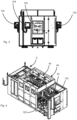
- Figure 2 shows a side view of a device according to the invention.
- the supply and discharge unit 2 with the main transport device 42 is shown, the actual treatment unit 4 with a large number of treatment devices and the media supply unit 6.
- Figure 3 shows a side view of the device according to the invention.
- the feed star 122 and the discharge star 123 can be seen, as well as a viewing window 125 through which the user can monitor the operation of the system.
- Reference numeral 124 denotes an operating device, such as a touch screen, to operate the device.
- Figure 4 shows a perspective view of a device according to the invention.
- the feed star 122 and the discharge star 123 can be seen, which transfer the containers to the main transport device 42.
- the treatment unit 4 with the individual treatment devices 44, 45, ... is arranged between the supply and discharge unit 2 and the media supply unit 6. In this way, a relatively compact design of the entire system can be achieved.
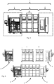
- Figure 5 shows a further representation of the device 1 according to the invention.
- the segments of the supply and discharge unit 2, the treatment unit 4 and the media supply unit 6 can be seen.
- a single treatment device 44 is also shown here. It can be seen that several or different numbers of treatment devices 4 can be introduced between the supply and discharge unit 2 and the media supply unit 6. In this way, the system can be expanded, for example.
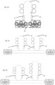
- FIG. 6 illustrates this situation.
- a block I is shown here, which has six treatment devices (three of which are not visible) and a second treatment block 11, which can be inserted into the system, so that, as in the lower part of the picture Figure 6 shown, a total of ten treatment facilities are planned.
- the transport length of the main transport device 42 has to be changed.
- FIG. 7 shows another possible arrangement of a device according to the invention.
- two devices 1 are provided, each of which has its own supply and discharge units 2 and treatment units 4.
- Two media supply units 6 are also provided, which, however, are supplied together by the respective reservoirs, i.e. the pump stations 62 for the vacuum and 64, i.e. the plasma supply.
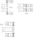
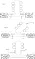
- FIGS. 8a to 8e show different arrangements for the device according to the invention. However, it should be noted that the embodiments are not limited to the possibilities shown in these figures.
- two devices 1 are provided, each of which has supply and discharge units 2, treatment units 4 and media supply units 6.
- these can be supplied with containers by a common transport device, whereby this common transport device can also be or have a turning device which turns the containers, for example aligning them with the mouth downwards for their treatment.
- Figure 8b shows a further embodiment, in which the arrangement of the respective reservoirs for the media is modified, for example in order to adapt to other spatial conditions.
- Figure 8c shows a further embodiment of a device according to the invention.
- a common supply and discharge unit 2 is provided, which supplies two separate container treatment units 4.
- two media supply units 6 are also provided here.
- a common feed and discharge unit 2 is also provided, which supplies two separate container treatment units 4.
- the spatial arrangement is again modified here.
- a supply and discharge unit 2 which provides a treatment unit 4 with a large number of container treatment devices. Due to the high number of container treatment devices, two reservoirs or possibly also two media supply units are provided here.
- the device can be adapted, in particular depending on the spatial conditions, in order to achieve the performance or throughput desired by the customer.
- Fig. 9 shows a schematic representation of an arrangement with two main transport devices, which, however, are supplied by a common inflow of containers 10 (arrow P1).
- the containers are alternately fed to the two main transport devices.
- the reference number 10a denotes a container which is fed to the lower main transport device 42 and the reference number 10b denotes a container which is fed to the upper main transport device.
- the reference number 10c denotes a blank space or an unoccupied holding device.
- the reference numeral 130 denotes a feed device to feed the containers to the entire treatment process and the reference numeral 140 denotes a discharge device to remove the containers from the process.
- the reference number 125 denotes a turning device or a turning path along which the containers are turned
- Fig. 10 shows a representation of a second transport device 200, which is also a turning device.
- An inlet star 122 designed as a division delay star can be seen, which transfers containers 10 to the second transport device 200 in an upright position.
- the containers are moved upwards by the transport device 200 over a curved section.
- the containers 10 are automatically turned over so that they are transported in an upside down position in the upper region of the second transport device 200.
- the containers 10 are transferred from the second transport device 200 to the main transport device 42. After the containers 10 have circulated around the first transport device 42, the containers 10 are again transferred to the second transport device 200 at the transfer point ÜP. The containers 10 are still in an upside down position, since such a position is preferred for coating. After the containers have been transported along a linear section of the transport device 200, they are transported down a curved section, whereby the containers 10 are automatically turned back into an upright position. The containers 10 are transferred in this upright position to the outlet star 123, which is preferably designed as a division delay star.
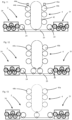
- FIG 11 shows a first embodiment of a treatment device according to the invention.
- the following figures are described only in relation to those elements which are now referred to Figure 11 differ from the configuration described.
- Reference numbers 31 and 34 indicate transport sections.
- the reference number 2 indicates the feed and discharge unit for the containers. This serves to supply containers (not shown) to the main transport device 42.
- the reference numbers 22 and 24 refer to transfer devices, such as transfer stars.
- the reference number 25 denotes a turning device, which can, for example, be designed in the form of a chain in order to turn the containers, that is, in particular to align them with their mouth downwards so that they are transferred to the main transport device 42 in this position.
- the reference number 4 denotes a total of one treatment unit.
- the reference numbers 44 and 45 identify two treatment devices, which in turn can each have treatment stations 44a, 45a or treatment elements.
- these treatment devices each have treatment transport devices 44b, 45b, which transport the containers to the respective treatment stations.
- the respective treatment stations, coating modules according to the invention are aligned at a right angle to the transfer route, that is, the route along which the containers are transported by the main transport device 42.
- the turning section 25 can, as mentioned above, be a chain and be arranged horizontally. However, it is also possible that this turning path is a long stator and is also aligned horizontally.
- the container is transferred to the transfer line in the middle of the turning device.
- Figure 12 differs from that Figure 11 in that two transfer stars are provided here to transfer the containers to the main transport device 42.
- These transfer stars are particularly preferably designed here as pitch delay stars, that is to say as transport devices which are suitable and intended to change a pitch between successive plastic containers.
- a chain is also preferably used as the turning path here.
- the coating modules are again arranged at right angles to the turning path and here the coating modules are arranged in a circle around the transfer path.
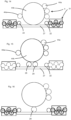
- the container transport device 44b is a transport wheel.
- the containers are transferred directly from the turning section to the transport wheel.
- two transfer stars 28, 29 are again provided and in the in Figure 16 shown embodiment a transfer star 28.
- Figure 17 shows an embodiment in which the coating module is also arranged at right angles to the transfer path and here again the containers are transferred in the middle.
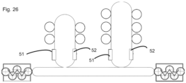
- two turning devices 51 and 52 are provided, which first turn the containers so that they can be treated by the treatment device and then turn them back again, that is to say into a position in which the mouth protrudes upwards.
- the main transport facility is at the in Figure 21 shown configuration arranged obliquely.
- the turning device 51, 52 are located in the area of the main transport device 42.
- the containers are turned over on the transfer route or the main transport device 42 and before the station S1 and after the station Sn the containers are turned back into the starting position.
- the transfer route or the main transport device can also be a chain wheel and/or a long stator.
- the containers are in in one sheet of the transfer line and the containers are taken over from the transport line in one sheet.
- a bypass device 58 is provided, with which it is possible to bypass the treatment device 4.
Description
Die vorliegende Erfindung bezieht sich auf eine Vorrichtung und ein Verfahren zum Behandeln von Behältnissen. Die vorliegende Erfindung wird unter Bezugnahme auf die Beschichtung von Kunststoffbehältnissen insbesondere die Beschichtung der Innenwandung von Kunststoffbehältnissen beschrieben. Es wird jedoch darauf hingewiesen, dass die hier beschriebene Erfindung auch auf andere verschiedene Typen zum Behandeln von Behältnissen, wie beispielsweise Sterilisationseinrichtungen, anwendbar ist. Allerdings ergeben sich durch bevorzugte Ausgestaltungen der Erfindung Vorteile, die insbesondere auch für Beschichtungseinrichtungen anwendbar sind.The present invention relates to a device and a method for treating containers. The present invention is described with reference to the coating of plastic containers, in particular the coating of the inner wall of plastic containers. However, it should be noted that the invention described here is also applicable to other different types of container handling, such as sterilization devices. However, preferred embodiments of the invention result in advantages that are particularly applicable to coating devices.
Aus dem Stand der Technik ist eine Beschichtungseinrichtung bekannt, welche einen Zuführstern aufweist, sowie ein Trägerrad, auf dem eine Vielzahl von Beschichtungsstationen angeordnet ist, welche die Behältnisse gleichzeitig transportieren und beschichten. Diese Vorrichtungen bringen gewisse Nachteile mit sich. Einerseits ist eine Wartung einzelner Beschichtungsstationen nicht möglich, ohne hierzu die gesamte Anlage anzuhalten.A coating device is known from the prior art, which has a feed star and a carrier wheel on which a large number of coating stations are arranged, which transport and coat the containers at the same time. These devices have certain disadvantages. On the one hand, maintenance of individual coating stations is not possible without stopping the entire system.
Weiterhin erlauben derartige Anlagen auch keine Erweiterung deren Kapazität bzw. eine variable Anpassung der Kapazität.Furthermore, such systems do not allow their capacity to be expanded or the capacity to be adjusted variably.
Aus der
Die
Aus der
Weiterhin ist aus der
Die
Der vorliegenden Erfindung liegt daher die Aufgabe zugrunde, eine Vorrichtung und ein Verfahren vorzuschlagen, welche insbesondere auch eine variable Erweiterbarkeit derartiger Anlagen ermöglichen. Dies wird erfindungsgemäß durch den Gegenstand des Anspruchs 1 erreicht. Vorteilhafte Ausführungsformen und Weiterbildungen sind Gegenstand der Unteransprüche.The present invention is therefore based on the object of proposing a device and a method which, in particular, also enable variable expandability of such systems. This is achieved according to the invention by the subject matter of
Eine Vorrichtung zum Behandeln von Behältnissen und insbesondere Kunststoffbehältnissen weist eine Behältnisbehandlungseinheit auf, wobei die Vorrichtung eine Haupttransporteinrichtungen aufweist, welche dazu geeignet und bestimmt ist, die Behältnisse entlang eines vorgegebenen Transportpfades zu transportieren, und wobei die erste Behälterbehandlungseinheit wenigstens eine Behandlungseinrichtung und bevorzugt wenigsten zwei Behandlungseinrichtungen aufweist, welche dazu geeignet und bestimmt sind, die Behältnisse in einer vorgegebenen Weise zu behandeln.A device for treating containers and in particular plastic containers has a container treatment unit, wherein the device has a main transport device which is suitable and intended for transporting the containers along a predetermined transport path, and wherein the first container treatment unit has at least one treatment device and preferably at least two treatment devices which are suitable and intended to treat the containers in a specified manner.
Weiterhin weist die Vorrichtung eine Zuführ- und Abführeinheit auf, welche dazu geeignet und bestimmt ist, wenigstens der ersten Behältnisbehandlungseinheit zu behandelnde Behältnisse zuzuführen und von der ersten Behältnisbehandlungseinheit behandelte Behältnisse abzuführen. Daneben weist die Vorrichtung eine Medienversorgungseinheit auf, welche dazu geeignet und bestimmt ist, der wenigstens ersten Behandlungseinrichtung Medien zuzuführen und/oder von der ersten Behandlungseinrichtung ein Medium wie insbesondere Luft abzuführen.Furthermore, the device has a supply and discharge unit which is suitable and intended to supply containers to be treated to at least the first container treatment unit and to discharge containers treated by the first container treatment unit. In addition, the device has a media supply unit which is suitable and intended to supply media to the at least first treatment device and/or to remove a medium, such as air in particular, from the first treatment device.
Die Vorrichtung ist modular aufgebaut und bevorzugt beliebig erweiterbar und oder veränderbar und es ist wenigstens eine weitere Behältnisbehandlungseinrichtung hinzufügbar, welche die Behältnisse in der vorgegebenen Weise behandelt und welche bevorzugt eine Transporteinrichtung aufweist, welche dazu geeignet und bestimmt ist, die Behältnisse entlang eines vorgegebenen Transportpfades zu transportieren, sowie wenigstens zwei Behandlungsstationen, welche dazu geeignet und bestimmt sind, die Behältnisse in einer vorgegebenen Weise zu behandeln.The device has a modular structure and can preferably be expanded and/or changed as desired and at least one further container treatment device can be added, which treats the containers in the predetermined manner and which preferably has a transport device which is suitable and intended to transport the containers along a predetermined transport path transport, as well as at least two treatment stations, which are suitable and intended to treat the containers in a predetermined manner.
Eine erfindungsgemäße Vorrichtung zum Beschichten von Behältnissen und insbesondere Kunststoffbehältnissen weist eine Behälterbehandlungseinheit auf, wobei die Vorrichtung eine Haupttransporteinrichtung aufweist, welche dazu geeignet und bestimmt ist, die Behältnisse entlang eines vorgegebenen Transtransportpfads zu transportieren, wobei die Behältnisbehandlungseinheit wenigstens zwei Beschichtungseinrichtungen zum Beschichten von Wandungen der Behältnisse aufweist, welche dazu geeignet und bestimmt sind, die Behältnisse in einer vorgegebenen Weise zu beschichten. Die Vorrichtung weist weiterhin eine Zuführ- und Abführeinheit auf, welche dazu geeignet und bestimmt ist, wenigstens der ersten Behandlungseinheit zu behandelnde Behältnisse zuzuführen und von der ersten Behandlungseinheit behandelte Behältnisse abzuführen und mit einer Medienversorgungseinheit, welche dazu geeignet und bestimmt ist, der wenigstens einen ersten Behandlungseinheit Medien zuzuführenA device according to the invention for coating containers and in particular plastic containers has a container treatment unit, the device having a main transport device which is suitable and intended to transport the containers along a predetermined transport path, the container treatment unit having at least two coating devices for coating walls of the containers which are suitable and intended to coat the containers in a predetermined manner. The device further has a supply and discharge unit, which is suitable and intended to supply containers to be treated to at least the first treatment unit and to remove containers treated by the first treatment unit, and with a media supply unit which is suitable and intended for this purpose, to the at least one first To supply media to the treatment unit
Erfindungsgemäß ist die Vorrichtung modular aufgebaut und/oder beliebig erweiterbar, derart dass wenigstens eine weitere Behältnisbeschichtungseinrichtung hinzufügbar ist, welche eine Behandlungstransporteinrichtung aufweist, welche dazu geeignet und bestimmt ist, die Behältnisse entlang eines vorgegebenen Transtransportpfads zu transportieren, mit wenigstens zwei Beschichtungsmodulen, welche dazu geeignet und bestimmt sind, die Behältnisse in der vorgegebenen Weise zu beschichten.According to the invention, the device has a modular structure and/or can be expanded as desired, such that at least one further container coating device can be added, which has a treatment transport device which is suitable and intended to transport the containers along a predetermined transtransport path at least two coating modules which are suitable and intended to coat the containers in the specified manner.
Es wird also vorgeschlagen, dass die Anlage modular aufgebaut und/oder beliebig erweiterbar ist und durch weitere Behandlungseinrichtungen ergänzt werden kann, um auf diese Weise beispielsweise die Kapazität zu erhöhen.It is therefore proposed that the system has a modular structure and/or can be expanded as desired and can be supplemented by further treatment devices in order, for example, to increase the capacity.
Im Folgenden wir der Begriff Vorrichtung zum Behandeln von Behältnissen für die Gesamte Anlage verwendet. Diese Vorrichtung weist eine Behandlungseinheit auf, welche wiederum eine oder mehrere Behandlungseinrichtungen aufweisen kann. Die Behandlungseinrichtungen wiederum weisen wenigstens eine und bevorzugt eine Vielzahl von Behandlungsstationen auf. Diese Behandlungseinrichtungen weisen wie oben erwähnt bevorzugt ebenfalls jeweils eine Transporteinrichtung auf, welche bevorzugt die Behältnisse den einzelnen Behandlungsstationen zuführen.In the following, the term device for treating containers is used for the entire system. This device has a treatment unit, which in turn can have one or more treatment devices. The treatment facilities in turn have at least one and preferably a large number of treatment stations. As mentioned above, these treatment devices also preferably each have a transport device, which preferably feeds the containers to the individual treatment stations.
Damit ist insbesondere die Anzahl der Behandlungseinrichtungen veränderbar und/oder anpassbar.This means that in particular the number of treatment facilities can be changed and/or adapted.
Bevorzugt ist die Haupttransporteinrichtung wenigstens hinsichtlich einer Eigenschaft anpassbar, insbesondere um die Vorrichtung an unterschiedliche Anzahlen von Behandlungseinrichtungen anzupassen. So kann beispielsweise die Aufnahmekapazität der Haupttransporteinrichtung hinsichtlich der Behältnisse angepasst werden und/oder eine Transportlänge der Haupttransporteinrichtung.The main transport device is preferably adaptable with regard to at least one property, in particular in order to adapt the device to different numbers of treatment devices. For example, the holding capacity of the main transport device can be adjusted with regard to the containers and/or a transport length of the main transport device.
Bei einer weiteren bevorzugten Ausführungsform ist die Haupttransporteinrichtung segmentartig aufgebaut und auf diese Weise insbesondere an eine unterschiedliche Anzahl von Behandlungseinrichtungen anpassbar.In a further preferred embodiment, the main transport device is constructed like a segment and in this way can be adapted in particular to a different number of treatment devices.
Insbesondere handelt es sich bei der ersten Behältnisbehandlungseinrichtung und der zweiten Behältnisbehandlungseinrichtung um gleichartige Einrichtungen, welche im Wesentlichen die gleichen Behandlungsvorgänge, wie Beschichtungsvorgänge durchführen.In particular, the first container treatment device and the second container treatment device are similar devices which carry out essentially the same treatment processes, such as coating processes.
Bei einer weiteren bevorzugten Ausführungsform werden jeweils die Zu- und Abführeinheit einerseits und die Medienversorgungseinheit andererseits beibehalten. Insbesondere kann es sich bei den Medien beispielsweise um Chemikalien handeln, mit denen die Kunststoffbehältnisse versorgt werden. Auch kann es sich bei dem Medium um "einen Unterdruck" handeln, das heißt, in diesem Falle versorgt die Medienversorgungseinheit die Behältnisse mit einem Unterdruck bzw. es wird Luft aus den Behältnissen abgeführt. Im Rahmen der vorliegenden Anmeldung werden daher unter Medien insbesondere Substanzen verstanden, nicht jedoch etwa elektrische Energie.In a further preferred embodiment, the supply and discharge unit on the one hand and the media supply unit on the other hand are retained. In particular can The media are, for example, chemicals with which the plastic containers are supplied. The medium can also be “a negative pressure”, that is, in this case the media supply unit supplies the containers with a negative pressure or air is removed from the containers. In the context of the present application, media is therefore understood to mean substances in particular, but not electrical energy.
Die Behandlungseinrichtungen selbst können wahlweise an die Haupttransporteinrichtung angekoppelt werden, um so die Produktionsleistung der Anlage verändern zu können. Bei einer weiteren bevorzugten Ausführungsform transportiert die Haupttransporteinrichtung die Behältnisse kontinuierlich. Die Zu- und Abführungseinheit führt die Behältnisse insbesondere der Haupttransporteinrichtung zu.The treatment devices themselves can optionally be coupled to the main transport device in order to be able to change the production output of the system. In a further preferred embodiment, the main transport device transports the containers continuously. The supply and removal unit feeds the containers, in particular, to the main transport device.
Bei einer weiteren bevorzugten Ausführungsform ist die Behandlungseinheit räumlich zwischen der Versorgungseinheit und der Medienversorgungseinheit angeordnet. Auf diese Weise kann ein besonders effizientes Systemlayout erreicht werden.In a further preferred embodiment, the treatment unit is spatially arranged between the supply unit and the media supply unit. In this way, a particularly efficient system layout can be achieved.
Dabei kann beispielsweise eine Frontseite vorgesehen sein, welche eine Anzeigeeinrichtung und insbesondere ein Touch Panel aufweist.For example, a front side can be provided which has a display device and in particular a touch panel.
Die Zuführ- und Abführeinheit kann dabei beispielsweise einen oder auch zwei oder auch mehrere Transportsterne aufweisen, welche dazu dienen, die Behältnisse der Haupttransporteinrichtung zuzuführen.The feed and discharge unit can, for example, have one or two or even more transport stars, which serve to feed the containers to the main transport device.
Bei einer weiteren bevorzugten Ausführungsform ist die Zu- und Abführeinheit auch dazu geeignet und bestimmt, der weiteren Behandlungseinrichtung zu behandelnde Behältnisse zuzuführen und von der weiteren Behandlungseinrichtung behandelte Behältnisse abzuführen. Dies bedeutet, dass die Zu- und Abführeinheit auch zum Versorgen der weiteren Behandlungseinrichtung dient.In a further preferred embodiment, the supply and discharge unit is also suitable and intended to supply containers to be treated to the further treatment device and to remove containers treated by the further treatment device. This means that the supply and discharge unit also serves to supply the other treatment facility.
Bei einer weiteren bevorzugten Ausführungsform ist die Medienversorgungseinheit dazu bestimmt, der weiteren Behandlungseinrichtung Medien zuzuführen, wobei, wie oben erwähnt, bei dem Medium auch eine Vakuumbeaufschlagung verstanden werden kann, das heißt, im physikalischen Sinne die Entnahme eines Mediums - nämlich von Luft.In a further preferred embodiment, the media supply unit is intended to supply media to the further treatment device, whereby, as mentioned above, the medium can also be understood as applying a vacuum, that is, in the physical sense, the removal of a medium - namely air.
Bei einer weiteren bevorzugten Ausführungsform ist die Medienversorgungseinheit dazu geeignet und bestimmt, den Behandlungseinrichtungen mehrere und/oder unterschiedliche Medien zuzuführen.In a further preferred embodiment, the media supply unit is suitable and intended to supply multiple and/or different media to the treatment devices.
Bei einer weiteren vorteilhaften Ausführungsform sind die Behältnisbehandlungseinrichtungen bezüglich des Transportpfades der Behältnisse in Serie und/oder parallel geschalten. Dies bedeutet, dass mehrere derartige Behandlungseinrichtungen entlang des Transportpfads der Behältnisse hintereinander angeordnet sein können. Im Falle eines parallelen Transports kann ein Transportpfad in zwei Teilpfade aufgespalten werden.In a further advantageous embodiment, the container treatment devices are connected in series and/or parallel with respect to the transport path of the containers. This means that several such treatment devices can be arranged one behind the other along the transport path of the containers. In the case of parallel transport, a transport path can be split into two sub-paths.
Bei einer weiteren bevorzugten Ausführungsform weist die Behandlungseinrichtung eine Behandlungstransporteinrichtung auf, welche die Behältnisse transportiert und wobei die Behältnisse von der Haupttransporteinrichtung an eine der Behandlungseinrichtungen zum Zwecke der Behandlung durch die Behandlungseinrichtung übergebbar sind, und die Behältnisse insbesondere nach deren Behandlung durch die Behandlungseinrichtung wieder an die Haupttransporteinrichtung übergebbar sind. Bei dieser Behältnistransporteinrichtung kann es sich beispielsweise um einen bewegbaren und/oder drehbaren Träger handeln.In a further preferred embodiment, the treatment device has a treatment transport device which transports the containers and the containers can be transferred from the main transport device to one of the treatment devices for the purpose of treatment by the treatment device, and the containers can be returned to the containers in particular after they have been treated by the treatment device Main transport facility can be transferred. This container transport device can be, for example, a movable and/or rotatable carrier.
Bei einer weiteren bevorzugten Ausführungsform ist die Behandlungstransporteinrichtung dazu geeignet und bestimmt, die Behältnisse getaktet zu transportieren. Bei einer weiteren bevorzugten Ausführungsform sind einzelne Behandlungsstationen der Behandlungseinheit stationär ausgebildet. Dies bedeutet, dass besonders bevorzugt der Behandlungsvorgang, beispielsweise ein Beschichtungsvorgang in einem stehenden Zustand der Behältnisse (bezüglich des Transportpfads) durchgeführt wird. Auch hier ist es wieder möglich, dass von der Haupttransporteinrichtung eine Vielzahl von Behältnissen abgenommen wird, und diese anschließend zu stehenden Behandlungsstationen geführt werden und dort behandelt, beispielsweise beschichtet, werden. Wie oben erwähnt ist die Haupttransporteinrichtung insbesondere dazu geeignet und bestimmt, die Behältnisse kontinuierlich zu transportieren.In a further preferred embodiment, the treatment transport device is suitable and intended to transport the containers in a clocked manner. In a further preferred embodiment, individual treatment stations of the treatment unit are designed to be stationary. This means that the treatment process, for example a coating process, is particularly preferably carried out in a stationary state of the containers (with respect to the transport path). Here too, it is again possible for a large number of containers to be removed from the main transport device and then to be guided to stationary treatment stations where they are treated, for example coated. As mentioned above, the main transport device is particularly suitable and intended to transport the containers continuously.
Bei einer bevorzugten Ausführungsform kann die Behandlungseinrichtung wenigstens drei, bevorzugt wenigstens vier Behandlungsstationen aufweisen. Bevorzugt weist die Behandlungseinrichtung höchstens 20, bevorzugt höchstens 18, bevorzugt höchstens 16, bevorzugt höchstens 14 und bevorzugt höchstens 10 Behandlungsstationen auf.In a preferred embodiment, the treatment device can have at least three, preferably at least four, treatment stations. The treatment device preferably has at most 20, preferably at most 18, preferably at most 16, preferably at most 14 and preferably at most 10 treatment stations.
Bei einer weiteren bevorzugten Ausführungsform sind die Behandlungseinrichtungen aus einer Gruppe von Behandlungseinrichtungen ausgewählt, welche erfindungsgemäße Beschichtungseinrichtungen zum Beschichten von Wandungen für Behältnisse, Druckeinrichtungen zum Bedrucken der Behältnisse, Sterilisiereinrichtungen zum Sterilisieren von Behältnissen, Fülleinrichtungen zum Befüllen von Behältnissen, Verschließeinrichtungen zum Verschließen von Behältnissen und dergleichen enthält. Bei den Behältnissen handelt es sich, wie oben erwähnt, insbesondere um Kunststoffbehältnisse, es wäre jedoch auch die Beschichtung von Glasbehältnissen denkbar.In a further preferred embodiment, the treatment devices are selected from a group of treatment devices, which include coating devices according to the invention for coating walls for containers, printing devices for printing on the containers, sterilizing devices for sterilizing containers, filling devices for filling containers, closing devices for closing containers and the like contains. As mentioned above, the containers are in particular plastic containers, but the coating of glass containers would also be conceivable.
Bei einer weiteren bevorzugten Ausführungsform weist die Vorrichtung eine Behältniswendeeinrichtung auf, die dazu geeignet und bestimmt ist, die zu transportierenden Behältnisse zu wenden. So ist es beispielsweise möglich, dass der Zu- und Abführreinrichtung die Behältnisse mit ihrer Mündung nach oben zugeführt werden, jedoch der eigentliche Behandlungsvorgang in einem gewendeten Zustand der Behältnisse, das heißt, ein Zustand, in dem die Mündung der Behältnisse nach unten ragt (das heißt näher der Erdmittelpunkt ist) erfolgt.In a further preferred embodiment, the device has a container turning device which is suitable and intended for turning the containers to be transported. For example, it is possible for the containers to be fed to the feed and discharge device with their mouths facing upwards, but the actual treatment process takes place in a turned state of the containers, that is, a state in which the mouth of the containers protrudes downwards (i.e means closer to the center of the earth).
Bei einer bevorzugten Ausführungsform ist die besagte Behältniswendeeinrichtung ein Bestandteil der Zu- und Abführeinheit. Das heißt, bei einer Erweiterung der Anlage wird diese Wendeeinrichtung beibehalten und bevorzugt nicht modifiziert. Es ist jedoch ebenso möglich, dass die Behältniswendeeinrichtung nicht Bestandteil der Zuführ- und Abführeinheit ist, sondern führt dieser die Behältnisse lediglich zu.In a preferred embodiment, said container turning device is a component of the feed and discharge unit. This means that when the system is expanded, this turning device is retained and preferably not modified. However, it is also possible that the container turning device is not part of the feed and discharge unit, but merely feeds the containers to it.
So ist es beispielsweise möglich, dass die Wendeeinrichtung ebenfalls als ein Umlauf- und Transportmittel, wie etwa eine umlaufende Kette ausgebildet ist. Diese kann dabei bevorzugt auch horizontal angeordnet sein und so ein Wenden der Behältnisse ermöglichen.For example, it is possible for the turning device to also be designed as a means of circulation and transport, such as a rotating chain. This can preferably also be arranged horizontally and thus enable the containers to be turned.
Auch wäre es möglich, dass die Wendeeinrichtung eine linearmotorische Antriebseinrichtung aufweist und insbesondere einen Langstator, der besonders bevorzugt ebenfalls horizontal angeordnet ist. So wäre es möglich, dass eine Kette oder ein derartiger Langstator, beispielsweise oval ausgeführt ist, und räumlich beispielsweise wie eine Fahrzeugkette beispielsweise eine Panzerkette verläuft. Auf diese Weise ist in besonders einfacher Weise ein Wenden der Behältnisse möglich.It would also be possible for the turning device to have a linear motor drive device and in particular a long stator, which is particularly preferably also arranged horizontally. It would be possible for a chain or such a long stator to be designed, for example, oval, and to run spatially, for example, like a vehicle chain, for example a tank chain. In this way, the containers can be turned over in a particularly simple manner.
Bei einer weiteren bevorzugten Ausführungsform weist die Vorrichtung eine Teilungsänderungseinrichtung auf, welche dazu geeignet und bestimmt ist, einen Abstand zweier in der Transporteinrichtung hintereinander angeordneter Behältnisse zu verändern. Dabei kann auch diese Teilungsänderungseinrichtung ein Bestandteil der oben erwähnten Zu- und Abführeinheit sein.In a further preferred embodiment, the device has a pitch changing device which is suitable and intended for changing a distance between two containers arranged one behind the other in the transport device. This pitch changing device can also be a component of the feed and discharge unit mentioned above.
Bei einer weiteren bevorzugten Ausführungsform ist wenigstens eine Behandlungseinrichtung und/oder Behandlungsstation und sind bevorzugt sämtliche Behandlungseinrichtungen und/oder die Behandlungsstationen senkrecht bezüglich eines Transportpfads der Behältnisse angeordnet. So kann es beispielsweise sein, dass diese Behandlungseinheit oberhalb oder unterhalb des Transportpfads der Behältnisse angeordnet sind. Dabei ist es weiterhin möglich, dass sich wenigstens ein Behandlungselement, im Wesentlichen senkrecht bezüglich des Transportpfads der Behältnisse bewegt. Dabei kann es sich beispielsweise um ein Element handeln, welches sich durch eine Mündung der Behältnisse in diese Behältnisse einführbar ist.In a further preferred embodiment, at least one treatment device and/or treatment station and preferably all treatment devices and/or the treatment stations are arranged perpendicularly with respect to a transport path of the containers. For example, it may be that this treatment unit is arranged above or below the transport path of the containers. It is also possible for at least one treatment element to move essentially vertically with respect to the transport path of the containers. This can, for example, be an element which can be inserted into these containers through an opening of the containers.
So kann beispielsweise ein Beschichtungsmodul in einem rechten Winkel zu der genannten Transferstrecke angeordnet sein.For example, a coating module can be arranged at a right angle to the transfer path mentioned.
Bei einer weiteren bevorzugten Ausführungsform weisen die Behandlungseinrichtungen in Form von Beschichtungseinrichtungen jeweils (Gas)Lanzen auf, die in die Behältnisse einführbar sind. Weiterhin weisen die Behandlungseinrichtungen auch Zündeinrichtungen wie insbesondere Zündelektroden auf. Bevorzugt bilden dabei eine Gaslanze und wenigstens eine Zündelektrode eine eigenständige Einheit.In a further preferred embodiment, the treatment devices in the form of coating devices each have (gas) lances that can be inserted into the containers. Furthermore, the treatment devices also have ignition devices such as, in particular, ignition electrodes. A gas lance and at least one ignition electrode preferably form an independent unit.
Weiterhin sind auch Medienzuführungen vorgesehen, um der besagten Gaslanze Beschichtungsmedien zuzuführen.Furthermore, media feeds are also provided in order to feed coating media to the gas lance.
Bevorzugt weist damit die Behandlungseinrichtung ein längliches, stabförmiges Element, insbesondere eine Lanze auf. Bevorzugt weist diese Lanze Öffnungen auf. Durch diese Öffnungen kann bevorzugt ein fließfähiges Medium in die Behältnisse eingeleitet werden. Bevorzugt handelt es sich bei diesem fließfähigen Medium um ein für den Plasmaprozess geeignetes Gas. Vorteilhaft kann es sich bei diesem Gas um ein Gemisch aus einem siliziumhaltigen Präkursor und Sauerstoff handeln, insbesondere für eine PECVD (=plasma enhanced chemical vapor deposition) mit Siliziumoxid. Es sind jedoch auch andere Gase denkbar, zum Beispiel Acetylen für die Abscheidung von sog. DLC-Schichten. Für eine Plasmasterilisation können z.B. Argon und Wasserdampf in die Behälter eingeleitet werden.The treatment device therefore preferably has an elongated, rod-shaped element, in particular a lance. This lance preferably has openings. A flowable medium can preferably be introduced into the containers through these openings. This flowable medium is preferably a gas suitable for the plasma process. This gas can advantageously be a mixture of a silicon-containing precursor and oxygen, in particular for a PECVD (=plasma enhanced chemical vapor deposition) with silicon oxide. However, other gases are also conceivable, for example acetylene for the deposition of so-called DLC layers. For plasma sterilization, for example, argon and water vapor can be introduced into the containers.
Bei einer weiteren bevorzugten Ausführungsform weist die Beschichtungseinrichtung bzw. weisen die Beschichtungsmodule Vakuumpumpen auf. Daneben sind auch Antriebe vorgesehen, die etwa eine Lanze in die Behältnisse bewegen. Bevorzugt können bei einer Beschichtungsvorrichtung Vakuumpumpen, Antriebe für Beschichtungslanzen und Pumpen für das Beschichtungsgas ausgeschaltet werden.In a further preferred embodiment, the coating device or the coating modules have vacuum pumps. In addition, drives are also provided that move a lance into the containers. In a coating device, vacuum pumps, drives for coating lances and pumps for the coating gas can preferably be switched off.
Bei einer weiteren bevorzugten Ausführungsform transportiert wenigstens eine Transporteinrichtung und insbesondere die Haupttransporteinrichtung die Behältnisse wenigstens abschnittsweise entlang eines Transportpfades, der von einem kreissegmentförmigen Verlauf abweicht bzw. einen von einem kreissegmentförmigen abweichenden Verlauf hat. Während in dem Stand der Technik üblicherweise Transporträder eingesetzt werden, wird hier vorgeschlagen, dass der Transportpfad einen unterschiedlichen Krümmungsverlauf aufweist. So kann der Transportpfad beispielsweise gerade Abschnitte aufweisen oder auch gekrümmte Abschnitte.In a further preferred embodiment, at least one transport device and in particular the main transport device transports the containers at least in sections along a transport path that deviates from a circular segment-shaped course or has a deviating circular segment-shaped course. While transport wheels are usually used in the prior art, it is proposed here that the transport path has a different curvature. For example, the transport path can have straight sections or curved sections.
Bevorzugt kann dieser Transportpfad in der Art eines Ovals ausgebildet sein, das heißt mit zwei geraden Streckenabschnitten und zwei Umlenkungsbereichen.This transport path can preferably be designed in the form of an oval, that is to say with two straight sections and two deflection areas.
Bei einer weiteren bevorzugten Ausführungsform weist wenigstens eine Transporteinrichtung ein umlaufendes Transportmittel und insbesondere eine Transportkette oder einen Langstator auf.In a further preferred embodiment, at least one transport device has a rotating means of transport and in particular a transport chain or a long stator.
Dabei ist besonders bevorzugt dieses Transportmittel horizontal ausgerichtet.This means of transport is particularly preferably aligned horizontally.
Weitere Vorteile und Ausführungsformen ergeben sich aus den beigefügten Zeichnungen. Darin zeigen:
- Fig. 1
- Eine schematische Darstellung zur Veranschaulichung des der Erfindung zugrundeliegenden Konzepts;
- Fig. 2
- Eine erfindungsgemäße Vorrichtung;
- Fig. 3
- Eine Seitenansicht der in
Figur 2 - Fig. 4
- Eine perspektivische Darstellung der in
Figur 2 - Fig. 5
- Eine weitere Darstellung zur Veranschaulichung des der Erfindung zugrunde liegenden Konzepts;
- Fig. 6
- Eine Darstellung einer Vorrichtung mit einer höheren Anzahl an Behandlungseinrichtungen;
- Fig. 7
- Eine Darstellung zur Veranschaulichung einer Vorrichtung mit einer weiter erhöhten Anzahl von Bearbeitungseinrichtungen;
- Fig. 8a - 8e
- Mehrere Aufbaukonzepte für erfindungsgemäße Vorrichtung;
- Fig. 9
- Eine Darstellung zur Veranschaulichung des Transports der Behältnisse;
- Fig. 10
- Eine perspektivische Darstellung zur Veranschaulichung des Transports und des Wendens der Behältnisse;
- Fig. 11-26
- unterschiedliche Ausgestaltungen von erfindungsgemäßen Behandlungseinrichtungen.
- Fig. 1
- A schematic representation to illustrate the concept underlying the invention;
- Fig. 2
- A device according to the invention;
- Fig. 3
- A side view of the in
Figure 2 device shown; - Fig. 4
- A perspective view of the in
Figure 2 device shown; - Fig. 5
- A further illustration to illustrate the concept underlying the invention;
- Fig. 6
- A representation of a device with a higher number of treatment devices;
- Fig. 7
- A representation to illustrate a device with a further increased number of processing devices;
- Fig. 8a - 8e
- Several construction concepts for the device according to the invention;
- Fig. 9
- A representation to illustrate the transport of the containers;
- Fig. 10
- A perspective view to illustrate the transport and turning of the containers;
- Fig. 11-26
- different designs of treatment devices according to the invention.
Das Bezugszeichen 42 kennzeichnet eine Haupttransporteinrichtung, welche einerseits die Behältnisse von einem Transportstern 122 übernimmt und sie wiederum an einen Transportstern 123 abgibt. Diese Haupttransporteinrichtung ragt auch in die Zu- und Abführeinheit 2 und erstreckt sich in eine Behältnisbehandlungseinheit 4. Von dieser Haupttransporteinrichtung 42 können die Behältnisse zum Zweck Ihrer Behandlung von den einzelnen Behandlungseinrichtungen abgenommen werden.The
Zu diesem Zweck weist die Haupttransporteinrichtung 42 eine Vielzahl von Halteelementen auf, welche zum Halten der einzelnen Behältnisse und zu deren Transport dienen. Bevorzugt werden dabei die Behältnisse in Reihe transportiert.For this purpose, the
Auch der Zuführstern 122 und der Abführstern 123 weisen eine Vielzahl von Halteeinrichtungen auf, um die Behältnisse vereinzelt zu transportieren.The
Weiterhin ist es auch möglich, dass eine der oder beide Transporteinrichtungen 122, 123 als sogenannte Teilungsverzugseinrichtung ausgebildet ist, welche dazu geeignet und bestimmt ist, eine Teilung bzw. einen Abstand der transportierten Behältnisse zu verändern. So können beispielsweise unterschiedliche Teilungen eingestellt werden.Furthermore, it is also possible for one or both
Die Haupttransporteinrichtung 42 kann dabei als eine umlaufende Kette ausgebildet sein, an der die einzelnen Halteeinrichtungen zum Halten der Behältnisse angeordnet sind. Es wäre jedoch auch möglich, dass die Haupttransporteinrichtung wie oben erwähnt als Langstator ausgebildet ist bzw. als linearmotorischer Antrieb.The
Die Bezugszeichen 44, 45 und 46 kennzeichnen einzelne Behandlungsstationen. Diese Behandlungseinrichtungen 44, 45, 46 weisen jeweils wiederum eine Behältnistransporteinrichtung 44b, 45b, 46b auf, wie etwa einen drehbaren Träger, der zum Transportieren der Behältnisse in die jeweiligen Behandlungsstationen dienen. Die Behandlungsstationen selbst sind bevorzugt stationär angeordnet, das heißt die Behältnisse werden diesen zur Behandlung übergeben. Bevorzugt transportieren diese einzelnen Behältnistransporteinrichtungen die Behältnisse getaktet.The
Das Bezugszeichen 6 kennzeichnet eine Medienversorgungseinheit. Diese kann einerseits die Behältnisse mit einem Unterdruck bzw. einem Vakuum versorgen und auch beispielsweise mit einem Plasma zu deren Beschichtung. Zu diesem Zweck bezeichnet das Bezugszeichen 62 einen Vakuumpumpenstand und das Bezugszeichen 64 einen Chemikalienstand.The
Wie einzeln erwähnt, kann die Anzahl und die Anordnung der Behältnisbehandlungseinrichtungen 44, 45, 46 verändert werden, um auf diese Weise die Produktionskapazität der Anlage verändern zu können.As mentioned individually, the number and arrangement of the
Bevorzugt ist es auch möglich, dass die Haupttransporteinrichtung 42 modular aufgebaut ist, sodass beispielsweise der Transportpfad der Haupttransporteinrichtung 42 verändert werden kann. Zu diesem Zweck können beispielsweise beim Vorsehen einer Kette mehrere Module eingeführt werden und eine entsprechende Transportkette ebenfalls erweitert werden. Falls die Haupttransporteinrichtung einen Langstator aufweist, können auch hier zusätzliche Langstatorelemente integriert werden, um den Transportweg zu verändern.It is also preferably possible for the
Das Bezugszeichen 124 kennzeichnet eine Bedieneinrichtung, wie etwa einen Touchscreen, um die Vorrichtung zu bedienen.
Die
Bei der in
Bei der in
Man erkennt, dass insgesamt die Vorrichtung insbesondere je nach räumlichen Gegebenheiten angepasst werden kann, um eine vom Kunden gewünschte Leistung bzw. einen vom Kunden gewünschten Durchsatz zu erreichen.It can be seen that overall the device can be adapted, in particular depending on the spatial conditions, in order to achieve the performance or throughput desired by the customer.
Dabei werden die Behältnisse abwechselnd den beiden Haupttransporteinrichtungen zugeführt. Dabei kennzeichnet das Bezugszeichen 10a ein Behältnis, welches der unteren Haupttransporteinrichtung 42 zugeführt wird und das Bezugszeichen 10b ein Behältnis, welches der oberen Haupttransporteinrichtung zugeführt wird. Das Bezugszeichen 10c kennzeichnet eine Leerstelle bzw. eine unbesetzte Halteeinrichtung.The containers are alternately fed to the two main transport devices. The
Das Bezugszeichen 130 kennzeichnet eine Zuführeinrichtung, um die Behältnisse dem gesamten Behandlungsprozess zuzuführen und das Bezugszeichen 140 eine Abführeinrichtung, um die Behältnisse von dem Prozess abzuführen. Das Bezugszeichen 125 kennzeichnet eine Wendeeinrichtung bzw. eine Wendestrecke, entlang derer die Behältnisse gewendet werdenThe
Am Übergabepunkt ÜP werden die Behältnisse 10 von der zweiten Transporteinrichtung 200 an die Haupttransporteinrichtung 42 übergeben. Nachdem die Behältnisse 10 die erste Transporteinrichtung 42 umlaufen haben, werden die Behältnisse 10 wieder am Übergabepunkt ÜP an die zweite Transporteinrichtung 200 übergeben. Die Behältnisse 10 befinden sich dabei noch immer in einer umgedrehten Position, da eine solche Position zum Beschichten bevorzugt ist. Nachdem die Behältnisse einen linearen Abschnitt der Transporteinrichtung 200 entlang transportiert wurden, werden sie einen gekrümmten Abschnitt nach unten transportiert, wodurch die Behältnisse 10 wieder automatisch in eine aufrechtstehende Position gewendet werden. Die Behältnisse 10 werden in dieser aufrechtstehenden Position an den Auslaufstern 123, der bevorzugt als Teilungsverzugsstern ausgestaltet ist, übergeben.At the transfer point ÜP, the
Die Bezugszeichen 31 und 34 kennzeichnen Transportabschnitte.
Das Bezugszeichen 2 kennzeichnet die Zuführ- und Abführeinheit für die Behältnisse. Diese dient dazu (nicht gezeichnete), Behältnisse der Haupttransporteinrichtung 42 zuzuführen. Dabei beziehen sich die Bezugszeichen 22 und 24 auf Übergabeeinrichtungen, wie beispielsweise Übergabesterne. Das Bezugszeichen 25 kennzeichnet eine Wendeeinrichtung, die beispielsweise in der Art einer Kette ausgeführt sein kann, um die Behältnisse zu wenden, das heißt, insbesondere mit ihrer Mündung nach unten so auszurichten, dass sie in dieser Position an die Haupttransporteinrichtung 42 übergeben werden. Das Bezugszeichen 4 kennzeichnet insgesamt die eine Behandlungseinheit.The
Die Bezugszeichen 44 und 45 kennzeichnen zwei Behandlungseinrichtungen, die jeweils wiederum Behandlungsstationen 44a, 45a bzw. Behandlungselemente aufweisen können. Daneben weisen diese Behandlungseinrichtungen jeweils Behandlungstransporteinrichtungen 44b, 45b auf, welche die Behältnisse zu den jeweiligen Behandlungsstationen transportieren.The
Bei der in
Die Wendestrecke 25 kann, wie oben erwähnt, eine Kette sein und horizontal angeordnet sein. Allerdings ist auch möglich, dass diese Wendestrecke ein Langstator ist und ebenfalls horizontal ausgerichtet ist.The turning
Bei der in
Als Wendestrecke wird jedoch auch hier bevorzugt eine Kette verwendet.However, a chain is also preferably used as the turning path here.
Bei der in
Bei der in
Bei der in
Bei dieser Ausgestaltung sind zwei Wendeeinrichtungen 51 und 52 vorgesehen, die zunächst die Behältnisse so drehen, dass sie von der Behandlungseinrichtung behandelt werden können und anschließend wieder zurückdrehen, das heißt in eine Position, der die Mündung nach oben ragt.In this embodiment, two
Die in
Auch bei den
Bei der in
Auch kann es ich bei der Transferstrecke bzw. der Haupttransporteinrichtung um ein Kettenrad und/oder einen Langstator handeln. Bei dieser Ausgestaltung werden die Behältnisse in einem Bogen der Transferstrecke übergeben und die Behältnisse werden von der Transportstrecke in einem Bogen übernommen. Zusätzlich ist bei der hier gezeigten Ausgestaltung eine Beipasseinrichtung 58 vorgesehen, mit der es möglich ist, die Behandlungseinrichtung 4 zu umgehen.The transfer route or the main transport device can also be a chain wheel and/or a long stator. In this embodiment, the containers are in in one sheet of the transfer line and the containers are taken over from the transport line in one sheet. In addition, in the embodiment shown here, a
Bei den in den
- 11
- Vorrichtungcontraption
- 22
- Zu- und AbführeinheitFeed and discharge unit
- 44
- BehältnisbehandlungseinheitContainer treatment unit
- 66
- MedienversorgungseinheitMedia supply unit
- 2828
- ÜbergabesternHandover star
- 2929
- ÜbergabesternHandover star
- 3131
- TransportabschnittTransport section
- 3434
- TransportabschnittTransport section
- 4242
- HaupttransporteinrichtungMain transportation facility
- 4242
- Reservoirreservoir
- 4444
- BehandlungseinrichtungTreatment facility
- 44a44a
- BehandlungsstationTreatment station
- 44b44b
- BehältnistransporteinrichtungContainer transport device
- 4545
- BehandlungseinrichtungTreatment facility
- 45a45a
- BehandlungsstationTreatment station
- 45b45b
- BehältnistransporteinrichtungContainer transport device
- 4646
- BehandlungseinrichtungTreatment facility
- 5151
- WendeeinrichtungTurning device
- 5252
- WendeeinrichtungTurning device
- 6262
- VakuumpumpenstandVacuum pump stand
- 6464
- ChemikalienstandChemical level
- 6464
- Reservoirreservoir
- 122122
- erster Transportstern, Zuführsternfirst transport star, feed star
- 123123
- zweiter Transportstern, Abführsternsecond transport star, discharge star
- 124124
- BedieneinrichtungOperating device
- 125125
- Sichtfensterviewing window
Claims (10)
- Apparatus (1) for coating containers and in particular plastic containers (10) having a container treatment unit (4), wherein the apparatus (1) has a main transport device (42) which is suitable and intended to transport the containers (10) along a predetermined transport path (P), wherein the container treatment unit (4) has at least two coating devices (44, 45, 46) for coating walls of the containers, which are suitable and intended to coat the containers (10) in a predetermined manner, having a feed and discharge unit (2) which is suitable and intended to feed containers to be treated to at least the first treatment unit (4) and to discharge containers (10) already treated from the first treatment unit (4) and having a media supply unit (6) which is suitable and intended to feed media to the at least one first treatment unit (4),
characterized in that
the apparatus (1) is modular and/or freely expandable in such a way that at least one further container coating device (44, 45, 46) can be added which has a container transport device (44b, 45b, 46b) which is suitable and intended to transport the containers (10) along a predetermined transport path having at least two coating modules (44a, 45a) which are suitable and intended to coat the containers in predetermined manner. - Apparatus according to claim 1,
characterized in that
the feed and discharge unit (2) is also suitable and intended to feed containers to be coated to the further coating device (44, 45, 46) and to discharge already coated containers (10) from the further coating device (44, 45, 46) and/or the media supply unit (6) is suitable and intended to feed media to the further coating device (44, 45, 46). - Apparatus (1) according to at least one of the preceding claims,
characterized in that
the container coating devices (44, 45, 46) are connected in series and/or in parallel relative to the transport path of the containers. - Apparatus (1) according to at least one of the preceding claims,
characterized in that
the container coating device (44, 45) has a treatment transport device (44b, 45b) which transports the containers and wherein the containers (10) are able to be handed over from the main transport device (42) to one and in particular to precisely only one of the coating devices (44, 45) for the purpose of coating by the coating device (44, 45) and the containers are able to be handed over to the main transport device (42) again, in particular after being coated by the coating device (44, 45). - Apparatus (1) according to at least one of the preceding claims,
characterized in that
the apparatus has a container turning device which is suitable and intended to turn the containers to be transported. - Apparatus (1) according to at least one of the preceding claims,
characterized in that
the apparatus has a pitch changing device which is suitable and intended to change a pitch of two containers being arranged one after the other in the transport direction. - Apparatus (1) according to at least one of the preceding claims,
characterized in that
at least one coating device (44, 45) is arranged to be perpendicular relative to the transport path of the containers. - Apparatus (1) according to at least one of the preceding claims,
characterized in that
at least one transport device and in particular the main transport device transports the containers at least sectionally along a transport path which has a course which deviates from a circular segment-shaped course. - Apparatus (1) according to at least one of the preceding claims,
characterized in that
at least one transport device has a circulating transport means and in particular a transport chain or a long stator. - Apparatus (1) according to at least one of the preceding claims,
characterized in that
the main transport device (42) is designed to be segmented and/or is able to be changed with respect to its receiving capacity of containers.
Applications Claiming Priority (1)
| Application Number | Priority Date | Filing Date | Title |
|---|---|---|---|
| DE102019126289.5A DE102019126289A1 (en) | 2019-09-30 | 2019-09-30 | Treatment device for containers with a modular structure |
Publications (2)
| Publication Number | Publication Date |
|---|---|
| EP3798158A1 EP3798158A1 (en) | 2021-03-31 |
| EP3798158B1 true EP3798158B1 (en) | 2023-11-15 |
Family
ID=72234647
Family Applications (1)
| Application Number | Title | Priority Date | Filing Date |
|---|---|---|---|
| EP20192281.2A Active EP3798158B1 (en) | 2019-09-30 | 2020-08-21 | Modular treatment device for containers |
Country Status (4)
| Country | Link |
|---|---|
| US (1) | US11834217B2 (en) |
| EP (1) | EP3798158B1 (en) |
| CN (1) | CN214242861U (en) |
| DE (1) | DE102019126289A1 (en) |
Family Cites Families (9)
| Publication number | Priority date | Publication date | Assignee | Title |
|---|---|---|---|---|
| ITUD20050192A1 (en) * | 2005-11-16 | 2007-05-17 | Internat Steel Co S P A | MODULAR WASHING INSTALLATION |
| DE102007017646A1 (en) * | 2007-04-13 | 2008-10-16 | Iwk Verpackungstechnik Gmbh | Packaging machine e.g. for packaging of products, has several work stations for packaging product in row on rail transport and built from several interrelated coupled modules |
| US9108835B2 (en) * | 2008-05-20 | 2015-08-18 | Dai Nippon Printing Co., Ltd. | Beverage filling method and apparatus |
| DE102010018153B4 (en) * | 2010-04-22 | 2023-11-02 | Krones Aktiengesellschaft | Transport device and transport method for a container treatment system and a container treatment system with such a transport device |
| DE102012213080A1 (en) * | 2012-07-25 | 2014-01-30 | Krones Ag | Device and method for equipping containers - basic machine |
| DE102015203042A1 (en) * | 2015-02-20 | 2016-08-25 | Krones Ag | Apparatus and method for distributing and grouping containers |
| DE102016200223B4 (en) * | 2016-01-12 | 2019-03-07 | Schott Ag | Method and device for siliconising the inner surface of hollow bodies |
| US10246202B2 (en) * | 2016-07-06 | 2019-04-02 | Khs Gmbh | Container-treatment machine |
| US9873569B1 (en) * | 2016-07-08 | 2018-01-23 | Khs Gmbh | Container treatment machine |
-
2019
- 2019-09-30 DE DE102019126289.5A patent/DE102019126289A1/en active Pending
-
2020
- 2020-08-21 EP EP20192281.2A patent/EP3798158B1/en active Active
- 2020-09-25 US US17/031,982 patent/US11834217B2/en active Active
- 2020-09-30 CN CN202022217192.5U patent/CN214242861U/en active Active
Also Published As
| Publication number | Publication date |
|---|---|
| DE102019126289A1 (en) | 2021-04-15 |
| EP3798158A1 (en) | 2021-03-31 |
| US11834217B2 (en) | 2023-12-05 |
| US20210094718A1 (en) | 2021-04-01 |
| CN214242861U (en) | 2021-09-21 |
Similar Documents
| Publication | Publication Date | Title |
|---|---|---|
| EP2246129B1 (en) | Cleaning assembly | |
| EP0621809B1 (en) | Bottle inspecting machine | |
| DE102006054846C5 (en) | Production plant for the production of solar cells in the inline process, as well as process for the integration of a batch process into a multi-lane inline production plant for solar cells | |
| EP4230557A1 (en) | Device and method for buffering articles | |
| EP0985224B1 (en) | Device and method for separately transporting substrates | |
| WO2020058135A1 (en) | Method and device for feeding products from a first process to a second process in a packaging plant | |
| EP3199246A1 (en) | Installation, treatment module and method for the treatment of objects | |
| EP3679169B1 (en) | Device for coating containers by means of a coating process and method for operating such a device | |
| EP0944544B1 (en) | Method and device for conveying individually held products | |
| EP3119717B1 (en) | Container treatment machine, and method for supplying and discharging containers to and from the container treatment machine | |
| EP1125678A2 (en) | Automation system for handling workpieces mounted on carriers | |
| EP3674439A1 (en) | Method and device for coating containers | |
| EP2489614B1 (en) | Method and device for treating containers with container rotation | |
| EP3798158B1 (en) | Modular treatment device for containers | |
| DE202013002267U1 (en) | Surface Treatment System | |
| WO2009130206A2 (en) | Cooling tunnel and method for operating the same | |
| DE102018132608A1 (en) | Device and method for treating containers | |
| EP3678815B1 (en) | Device for coating containers | |
| WO2021063644A1 (en) | Device for treating containers with the possibility of performing maintenance during an ongoing operation | |
| EP3236511A1 (en) | Method and apparatus for the removal of battery cells from a rectangular surrounding | |
| EP0646055B1 (en) | Process and device for transferring workpieces | |
| DE10332163B4 (en) | Vacuum coating system with clustered process stations | |
| EP1076021B1 (en) | Method and device for combining streams of articles | |
| DE102014102116A1 (en) | Apparatus for treating containers | |
| DE10224934B4 (en) | Apparatus and method for CVD coatings |
Legal Events
| Date | Code | Title | Description |
|---|---|---|---|
| PUAI | Public reference made under article 153(3) epc to a published international application that has entered the european phase |
Free format text: ORIGINAL CODE: 0009012 |
|
| STAA | Information on the status of an ep patent application or granted ep patent |
Free format text: STATUS: THE APPLICATION HAS BEEN PUBLISHED |
|
| AK | Designated contracting states |
Kind code of ref document: A1 Designated state(s): AL AT BE BG CH CY CZ DE DK EE ES FI FR GB GR HR HU IE IS IT LI LT LU LV MC MK MT NL NO PL PT RO RS SE SI SK SM TR |
|
| AX | Request for extension of the european patent |
Extension state: BA ME |
|
| STAA | Information on the status of an ep patent application or granted ep patent |
Free format text: STATUS: REQUEST FOR EXAMINATION WAS MADE |
|
| 17P | Request for examination filed |
Effective date: 20210915 |
|
| RBV | Designated contracting states (corrected) |
Designated state(s): AL AT BE BG CH CY CZ DE DK EE ES FI FR GB GR HR HU IE IS IT LI LT LU LV MC MK MT NL NO PL PT RO RS SE SI SK SM TR |
|
| STAA | Information on the status of an ep patent application or granted ep patent |
Free format text: STATUS: EXAMINATION IS IN PROGRESS |
|
| 17Q | First examination report despatched |
Effective date: 20220523 |
|
| GRAP | Despatch of communication of intention to grant a patent |
Free format text: ORIGINAL CODE: EPIDOSNIGR1 |
|
| STAA | Information on the status of an ep patent application or granted ep patent |
Free format text: STATUS: GRANT OF PATENT IS INTENDED |
|
| RIC1 | Information provided on ipc code assigned before grant |
Ipc: B65G 54/02 20060101ALI20230428BHEP Ipc: B67C 3/22 20060101ALI20230428BHEP Ipc: B65G 47/86 20060101ALI20230428BHEP Ipc: B65G 37/02 20060101ALI20230428BHEP Ipc: B05D 7/22 20060101ALI20230428BHEP Ipc: B41J 3/407 20060101ALI20230428BHEP Ipc: B67C 7/00 20060101ALI20230428BHEP Ipc: B67C 3/24 20060101ALI20230428BHEP Ipc: B65G 37/00 20060101AFI20230428BHEP |
|
| INTG | Intention to grant announced |
Effective date: 20230530 |
|
| GRAS | Grant fee paid |
Free format text: ORIGINAL CODE: EPIDOSNIGR3 |
|
| GRAA | (expected) grant |
Free format text: ORIGINAL CODE: 0009210 |
|
| STAA | Information on the status of an ep patent application or granted ep patent |
Free format text: STATUS: THE PATENT HAS BEEN GRANTED |
|
| AK | Designated contracting states |
Kind code of ref document: B1 Designated state(s): AL AT BE BG CH CY CZ DE DK EE ES FI FR GB GR HR HU IE IS IT LI LT LU LV MC MK MT NL NO PL PT RO RS SE SI SK SM TR |
|
| REG | Reference to a national code |
Ref country code: CH Ref legal event code: EP Ref country code: GB Ref legal event code: FG4D Free format text: NOT ENGLISH |
|
| REG | Reference to a national code |
Ref country code: DE Ref legal event code: R096 Ref document number: 502020006010 Country of ref document: DE |
|
| REG | Reference to a national code |
Ref country code: IE Ref legal event code: FG4D Free format text: LANGUAGE OF EP DOCUMENT: GERMAN |
|
| P01 | Opt-out of the competence of the unified patent court (upc) registered |
Effective date: 20231113 |
|
| REG | Reference to a national code |
Ref country code: LT Ref legal event code: MG9D |
|
| REG | Reference to a national code |
Ref country code: NL Ref legal event code: MP Effective date: 20231115 |
|
| PG25 | Lapsed in a contracting state [announced via postgrant information from national office to epo] |
Ref country code: GR Free format text: LAPSE BECAUSE OF FAILURE TO SUBMIT A TRANSLATION OF THE DESCRIPTION OR TO PAY THE FEE WITHIN THE PRESCRIBED TIME-LIMIT Effective date: 20240216 |
|
| PG25 | Lapsed in a contracting state [announced via postgrant information from national office to epo] |
Ref country code: IS Free format text: LAPSE BECAUSE OF FAILURE TO SUBMIT A TRANSLATION OF THE DESCRIPTION OR TO PAY THE FEE WITHIN THE PRESCRIBED TIME-LIMIT Effective date: 20240315 |
|
| PG25 | Lapsed in a contracting state [announced via postgrant information from national office to epo] |
Ref country code: LT Free format text: LAPSE BECAUSE OF FAILURE TO SUBMIT A TRANSLATION OF THE DESCRIPTION OR TO PAY THE FEE WITHIN THE PRESCRIBED TIME-LIMIT Effective date: 20231115 |
|
| PG25 | Lapsed in a contracting state [announced via postgrant information from national office to epo] |
Ref country code: NL Free format text: LAPSE BECAUSE OF FAILURE TO SUBMIT A TRANSLATION OF THE DESCRIPTION OR TO PAY THE FEE WITHIN THE PRESCRIBED TIME-LIMIT Effective date: 20231115 |