EP3798143B1 - Welding head for a strapping machine, and counter pressure plate that can be used therein - Google Patents
Welding head for a strapping machine, and counter pressure plate that can be used therein Download PDFInfo
- Publication number
- EP3798143B1 EP3798143B1 EP20195095.3A EP20195095A EP3798143B1 EP 3798143 B1 EP3798143 B1 EP 3798143B1 EP 20195095 A EP20195095 A EP 20195095A EP 3798143 B1 EP3798143 B1 EP 3798143B1
- Authority
- EP
- European Patent Office
- Prior art keywords
- pressure plate
- counter pressure
- welding head
- strap
- front edge
- Prior art date
- Legal status (The legal status is an assumption and is not a legal conclusion. Google has not performed a legal analysis and makes no representation as to the accuracy of the status listed.)
- Active
Links
- 238000003466 welding Methods 0.000 title claims description 36
- 238000003780 insertion Methods 0.000 claims description 23
- 230000037431 insertion Effects 0.000 claims description 23
- 230000001154 acute effect Effects 0.000 claims description 4
- 230000007704 transition Effects 0.000 claims description 3
- 238000000034 method Methods 0.000 description 5
- 230000008569 process Effects 0.000 description 5
- 238000007493 shaping process Methods 0.000 description 2
- 229910000831 Steel Inorganic materials 0.000 description 1
- 230000009471 action Effects 0.000 description 1
- VNTLIPZTSJSULJ-UHFFFAOYSA-N chromium molybdenum Chemical compound [Cr].[Mo] VNTLIPZTSJSULJ-UHFFFAOYSA-N 0.000 description 1
- 230000006835 compression Effects 0.000 description 1
- 238000007906 compression Methods 0.000 description 1
- 230000001419 dependent effect Effects 0.000 description 1
- 238000011161 development Methods 0.000 description 1
- 230000018109 developmental process Effects 0.000 description 1
- 238000010438 heat treatment Methods 0.000 description 1
- 230000006872 improvement Effects 0.000 description 1
- 230000003993 interaction Effects 0.000 description 1
- 239000007769 metal material Substances 0.000 description 1
- 239000010959 steel Substances 0.000 description 1
Images


Classifications
-
- B—PERFORMING OPERATIONS; TRANSPORTING
- B65—CONVEYING; PACKING; STORING; HANDLING THIN OR FILAMENTARY MATERIAL
- B65B—MACHINES, APPARATUS OR DEVICES FOR, OR METHODS OF, PACKAGING ARTICLES OR MATERIALS; UNPACKING
- B65B13/00—Bundling articles
- B65B13/18—Details of, or auxiliary devices used in, bundling machines or bundling tools
- B65B13/24—Securing ends of binding material
- B65B13/32—Securing ends of binding material by welding, soldering, or heat-sealing; by applying adhesive
-
- B—PERFORMING OPERATIONS; TRANSPORTING
- B65—CONVEYING; PACKING; STORING; HANDLING THIN OR FILAMENTARY MATERIAL
- B65B—MACHINES, APPARATUS OR DEVICES FOR, OR METHODS OF, PACKAGING ARTICLES OR MATERIALS; UNPACKING
- B65B13/00—Bundling articles
- B65B13/02—Applying and securing binding material around articles or groups of articles, e.g. using strings, wires, strips, bands or tapes
- B65B13/04—Applying and securing binding material around articles or groups of articles, e.g. using strings, wires, strips, bands or tapes with means for guiding the binding material around the articles prior to severing from supply
-
- B—PERFORMING OPERATIONS; TRANSPORTING
- B65—CONVEYING; PACKING; STORING; HANDLING THIN OR FILAMENTARY MATERIAL
- B65B—MACHINES, APPARATUS OR DEVICES FOR, OR METHODS OF, PACKAGING ARTICLES OR MATERIALS; UNPACKING
- B65B13/00—Bundling articles
- B65B13/02—Applying and securing binding material around articles or groups of articles, e.g. using strings, wires, strips, bands or tapes
- B65B13/16—Applying and securing binding material around articles or groups of articles, e.g. using strings, wires, strips, bands or tapes with means for severing the binding material from supply and then applying it around the articles
-
- B—PERFORMING OPERATIONS; TRANSPORTING
- B65—CONVEYING; PACKING; STORING; HANDLING THIN OR FILAMENTARY MATERIAL
- B65B—MACHINES, APPARATUS OR DEVICES FOR, OR METHODS OF, PACKAGING ARTICLES OR MATERIALS; UNPACKING
- B65B13/00—Bundling articles
- B65B13/18—Details of, or auxiliary devices used in, bundling machines or bundling tools
- B65B13/22—Means for controlling tension of binding means
-
- B—PERFORMING OPERATIONS; TRANSPORTING
- B65—CONVEYING; PACKING; STORING; HANDLING THIN OR FILAMENTARY MATERIAL
- B65B—MACHINES, APPARATUS OR DEVICES FOR, OR METHODS OF, PACKAGING ARTICLES OR MATERIALS; UNPACKING
- B65B13/00—Bundling articles
- B65B13/18—Details of, or auxiliary devices used in, bundling machines or bundling tools
- B65B13/24—Securing ends of binding material
Definitions
- the invention relates to a welding head for a strapping machine having the features indicated in the pre-characterizing clause of Patent Claim 1 and to a counter pressure plate that can be used therein.
- a welding head of the type in question comprises as essential components strap clamps, strap manipulators, cutting devices for the strap, a welding device for the strap sections, which overlap in the welding head, and a counter pressure plate, which can be inserted into the strap loop, for supporting the overlapping strap sections, at least during the welding thereof.
- a stack of newspapers or a cardboard box is inserted into a vertically suspended strap clamped at one end, and the strap is laid in a loop around the product by means of corresponding manipulators, and the clamped strap end overlaps with a corresponding strap section to be welded.
- the "counter pressure plate” which, as the loop is formed, must be inserted from the side between the product, on the one hand, and the two strap sections to be welded, on the other hand, in order to be able to serve as a support and a stop for the welding jaws of the welding device to allow the compression and heating of the two strap sections.
- EP 3 137 381 B1 proposes a separate strap-guiding manipulator which guides the relevant strap section away from the product before the counter pressure plate is inserted, and positions it in such a way that a defined free space is created for the insertion of the counter pressure plate.
- this additional manipulator requires a considerable additional design effort.
- the double bevel with a slope of the front edge which deviates at an acute angle in the plane of the counter pressure plate from the normal to the insertion direction, at least over a partial width, on the one hand, and a thickness bevel due to a tapering run out, in the thickness direction, of the counter pressure plate towards the front edge are particularly effective since the leading region of the counter pressure plate, which is the first to enter the clearance during the insertion movement, thus has an end face that is optimally narrow in the width and thickness directions.
- the angle of the slope here can be 10° to 20°, preferably about 15°.
- the dimension thereof in terms of width can correspond to a partial width of 70% to 80%, preferably about 73%, of the total width of the counter pressure plate.
- the provision of a taper of the counter pressure plate over 10% to 20%, preferably about 15%, of the maximum depth thereof in the insertion direction has proven to be an advantageous embodiment.
- Rounded transitions between edge sections of the counter pressure plate have proven to be a further advantageous measure for the improvement of the counter pressure plate. Furthermore, depressions for the engagement of other components of the welding head during the strapping and welding process can be provided.
- the longitudinal strapping machine shown has a working plane 1 indicated in chain-dotted lines, which (although not illustrated) comprises a work table with conveying devices integrated therein for conveying the product 2 to be strapped through the machine in the conveying direction T and apertures for the strap 3.
- the welding head Arranged below the working plane is the welding head, which is illustrated particularly in Figure 3 with its components, is denoted overall by 4 and, for example, has strap clamps 5, 6.1, 6.2, strap manipulators 7, 8, cutting devices 9, a welding device 10 having a welding jaw 11, and a counter pressure plate 12.
- the interplay between these components and the overall functioning of the strapping machine will be omitted at this point to avoid long-winded unnecessary explanations since this does not belong to the heart of the invention to be described here.
- the clearance 13 which is obtained between the working plane 1 and the strap 3 relatively close to the start of the strapping process after the insertion of the product 2 into the suspended strap 3 and the taking along thereof into the configuration shown in Figure 1 .
- the counter pressure plate 12 is then to be inserted into this clearance 13 from the side, i.e. perpendicularly to the plane of the drawing in this figure.
- the strap 3 is pulled down away from the working plane 1 by a corresponding strap-guiding manipulator before this insertion, and the clearance 13 is thereby considerably enlarged. Because of the special configuration of the counter pressure plate 12, this does not need to happen in the present case.
- the start 14 of the strap is still held by strap clamp 5, and the strap 3 is furthermore fixed in the welding head 4 by strap clamp 6.1 together with the counter pressure plate 12 for the subsequent welding process.
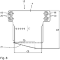
- the counter pressure plate 12 which is made from a metallic material such as chromium-molybdenum steel, is achieved by means of the special shaping of the counter pressure plate 12, which will be explained with reference to Figures 4 to 8 .
- the counter pressure plate has a basically rectangular main body 17, which is provided at its end facing away from the insertion direction E in relation to the clearance 13 with two lateral assembly projections 18, 19, which are thicker than the thickness D and each have screw holes 20.
- the main body 17 has a double bevel to form a structure similar to a cutting edge.
- the front edge 21 has a slope 22 in that the front edge 21 runs towards the insertion direction E at an acute angle W of, for example, 15° to the normal N over a partial width TB of, for example, 73% of the total width GB of the main body 17.
- a second bevel in the form of a thickness bevel 24 is provided in that the counter pressure plate 12 tapers on one side from the underside 25 of the main body 17 towards the front edge 21 in the insertion direction E.
- This thickness bevel 24 extends over 15% of the maximum depth MT of the main body, for example.
- the counter pressure plate 12 has various depressions 26, 27, 28 to form free spaces for the engagement of various components of the welding head 4.
Description
- The invention relates to a welding head for a strapping machine having the features indicated in the pre-characterizing clause of
Patent Claim 1 and to a counter pressure plate that can be used therein. - A welding head of the type in question, as known for example from
EP 3 137 381 B1 - During this insertion of the counter pressure plate from the side, there is now the problem that the clearance between the strap and the underside of the product or of the support of the strapping machine is too narrow for this purpose and therefore there may be a risk that the counter pressure plate will take along a strap section as it is inserted into this clearance, with the result that the strap is trapped in the welding head or is damaged in some other way.
- To avoid these problems,
EP 3 137 381 B1 - Accordingly, it is an underlying object of the invention to specify a welding head that has an improved counter pressure plate, by means of which the above problems are circumvented with significantly less design effort.
- This object is at least partly achieved by the features indicated in the characterizing part of
Claims - By virtue of this special shaping, the risk of troublesome take-along of the strap is at least reduced to such a significant extent, even in the case of a narrow clearance, that reliable operation of the strapping machine is nevertheless ensured. By virtue of the structure of the front edge similar to a cutting edge, said front edge can as it were "slip into" the clearance. If the strap is touched by the counter pressure plate, it is pushed away only slightly but not taken along and trapped.
- Advantageous developments of the counter pressure plate are indicated in
dependent Claims 2 to 7 and 9. Thus, the double bevel with a slope of the front edge, which deviates at an acute angle in the plane of the counter pressure plate from the normal to the insertion direction, at least over a partial width, on the one hand, and a thickness bevel due to a tapering run out, in the thickness direction, of the counter pressure plate towards the front edge are particularly effective since the leading region of the counter pressure plate, which is the first to enter the clearance during the insertion movement, thus has an end face that is optimally narrow in the width and thickness directions. - Various design embodiments of the bevels have proven advantageous for trouble-free insertion of the counter pressure plate. Thus, the angle of the slope here can be 10° to 20°, preferably about 15°. The dimension thereof in terms of width can correspond to a partial width of 70% to 80%, preferably about 73%, of the total width of the counter pressure plate. For the thickness bevel, the provision of a taper of the counter pressure plate over 10% to 20%, preferably about 15%, of the maximum depth thereof in the insertion direction has proven to be an advantageous embodiment.
- Rounded transitions between edge sections of the counter pressure plate have proven to be a further advantageous measure for the improvement of the counter pressure plate. Furthermore, depressions for the engagement of other components of the welding head during the strapping and welding process can be provided.
- Further features, details and advantages of the invention will become apparent from the following description of an exemplary embodiment with reference to the appended drawings, in which:
-
Figs 1 to 3 show schematic views of a strapping machine in different intermediate strapping steps, -
Figs 4 and 5 show perspective views of a counter pressure plate obliquely from above and below, -
Fig. 6 shows a bottom view of this counter pressure plate, -
Fig. 7 shows a vertical section through this counter pressure plate along section line VII-VII inFig. 6 , and -
Fig. 8 shows a plan view of this counter pressure plate. - Basic components of a longitudinal strapping machine will be outlined briefly with reference to
Figs. 1 to 3 by way of introduction to the description of the exemplary embodiment. Thus, the longitudinal strapping machine shown has a workingplane 1 indicated in chain-dotted lines, which (although not illustrated) comprises a work table with conveying devices integrated therein for conveying theproduct 2 to be strapped through the machine in the conveying direction T and apertures for thestrap 3. - Arranged below the working plane is the welding head, which is illustrated particularly in
Figure 3 with its components, is denoted overall by 4 and, for example, hasstrap clamps 5, 6.1, 6.2,strap manipulators cutting devices 9, awelding device 10 having awelding jaw 11, and acounter pressure plate 12. The interplay between these components and the overall functioning of the strapping machine will be omitted at this point to avoid long-winded unnecessary explanations since this does not belong to the heart of the invention to be described here. Reference can be made to the functional description inEP 3 137 381 B1 - Important for the present invention is the
clearance 13 which is obtained between theworking plane 1 and thestrap 3 relatively close to the start of the strapping process after the insertion of theproduct 2 into the suspendedstrap 3 and the taking along thereof into the configuration shown inFigure 1 . As shown inFig. 2 , thecounter pressure plate 12 is then to be inserted into thisclearance 13 from the side, i.e. perpendicularly to the plane of the drawing in this figure. In the prior art in accordance withEP 3 137 381 B1strap 3 is pulled down away from the workingplane 1 by a corresponding strap-guiding manipulator before this insertion, and theclearance 13 is thereby considerably enlarged. Because of the special configuration of thecounter pressure plate 12, this does not need to happen in the present case. - In the intermediate step shown in
Fig. 2 , thestart 14 of the strap is still held bystrap clamp 5, and thestrap 3 is furthermore fixed in thewelding head 4 by strap clamp 6.1 together with thecounter pressure plate 12 for the subsequent welding process. - Various manipulation processes known per se take place in the
welding head 4, thus giving rise to the intermediate configuration illustrated inFig. 3 . Here, thestart 14 of the strap has been released bystrap clamp 5, and has likewise been fixed against thecounter pressure plate 12 by strap clamp 6.2. After guiding thestrap 3 around theproduct 2, thestrap manipulator 7 has moved the corresponding strap section between thestrap clamp 5, which once again holds thestrap 3 there. This section then represents the start 14' of the strap for the next strapping process, and this is separated by thecutting device 9 from thestrap 3 currently being processed. The now overlappingwelding sections strap 3 can then be welded to one another by the thermal and mechanical action of thewelding jaw 11 while being held up by thecounter pressure plate 12, and in this way the strap loop around theproduct 2 can be closed. Thecounter pressure plate 12 then moves sideways out of theclearance 13 again, the strap clamps 6.1, 6.2 release thestrap loop 3, thewelding jaw 11 moves back, and the fully strappedproduct 2 can be moved out of the machine in conveying direction T. - The trouble-free insertion of the
counter pressure plate 12, which is made from a metallic material such as chromium-molybdenum steel, is achieved by means of the special shaping of thecounter pressure plate 12, which will be explained with reference toFigures 4 to 8 . Thus, the counter pressure plate has a basically rectangularmain body 17, which is provided at its end facing away from the insertion direction E in relation to theclearance 13 with twolateral assembly projections screw holes 20. At thefront edge 21 facing in the insertion direction E, which is in the lead during insertion, themain body 17 has a double bevel to form a structure similar to a cutting edge. - Thus, on the one hand, the
front edge 21 has aslope 22 in that thefront edge 21 runs towards the insertion direction E at an acute angle W of, for example, 15° to the normal N over a partial width TB of, for example, 73% of the total width GB of themain body 17. - On the other hand - as is particularly apparent from the section shown in
Fig. 7 - a second bevel in the form of athickness bevel 24 is provided in that thecounter pressure plate 12 tapers on one side from theunderside 25 of themain body 17 towards thefront edge 21 in the insertion direction E. Thisthickness bevel 24 extends over 15% of the maximum depth MT of the main body, for example. - Although not explicitly indicated in the drawings, all the transitions between various edge sections of the
counter pressure plate 12 may be rounded. Moreover, thecounter pressure plate 12 hasvarious depressions welding head 4.
Claims (9)
- Welding head for a strapping machine, in particular for longitudinally strapping a product, comprising- strap clamps (5, 6.1, 6.2),- strap manipulators (7, 8),- cutting devices (9) for the strap (3),- a welding device (10) for the strap welding sections (15, 16), which overlap in the welding head (4), and- a counter pressure plate (12), which can be inserted into the strapping loop, for supporting the overlapping strap welding sections (15, 16), at least during the welding thereof,characterized in that- the front edge (21) of the counter pressure plate (12), said edge facing in the insertion direction (E) and moving in the lead during insertion, is bevelled to form a structure similar to a cutting edge.
- Welding head according to Claim 1, characterized in that the leading front edge (21) of the counter pressure plate (12) has two bevels, namely- a slope (22) of the front edge (21), which deviates at an acute angle (W) in the plane of the counter pressure plate (12) from the normal (N) to the insertion direction (E), at least over a partial width (TB), and- a thickness bevel (24) due to a tapering run out, in the thickness direction, of the counter pressure plate (12) towards the front edge (21).
- Welding head according to Claim 2, characterized in that the angle (W) of the slope (22) is 10° to 20°, preferably about 15°.
- Welding head according to Claim 2 or 3, characterized by a slope (22) over a partial width (TB) of 70% to 80%, preferably about 73%, of the total width (GB) of the counter pressure plate (12).
- Welding head according to any of Claims 2 to 4, characterized in that the taper of the counter pressure plate (12) which forms the thickness bevel (24) extends over 10% to 20%, preferably about 15%, of the maximum depth (MT) of the counter pressure plate (12) in the insertion direction (E).
- Welding head according to Claim 5, characterized in that the transitions between the edge sections of the counter pressure plate (12) are rounded.
- Welding head according to any of the preceding claims, characterized in that the counter pressure plate (12) has depressions (26, 27, 28) for the engagement of other components of the welding head (4).
- Use of a counter pressure plate in a welding head according to any of the preceding claims, characterized in that the front edge (21) of the counter pressure plate (12), said edge facing in the insertion direction (E) and moving in the lead during insertion, is bevelled to form a structure similar to a cutting edge.
- Use according to Claim 8, characterized in that the leading front edge (21) of the counter pressure plate has two bevels, namely- a slope (22) of the front edge (21), which deviates at an acute angle (W) in the plane of the counter pressure plate (12) from the normal (N) to the insertion direction (E), at least over a partial width (TB), and- a thickness bevel (24) due to a tapering run out, in the thickness direction, of the counter pressure plate (12) towards the front edge (21).
Applications Claiming Priority (1)
| Application Number | Priority Date | Filing Date | Title |
|---|---|---|---|
| DE102019215010.1A DE102019215010B4 (en) | 2019-09-30 | 2019-09-30 | Welding head for a strapping machine and counter pressure plate that can be used in it |
Publications (2)
| Publication Number | Publication Date |
|---|---|
| EP3798143A1 EP3798143A1 (en) | 2021-03-31 |
| EP3798143B1 true EP3798143B1 (en) | 2022-08-17 |
Family
ID=72432748
Family Applications (1)
| Application Number | Title | Priority Date | Filing Date |
|---|---|---|---|
| EP20195095.3A Active EP3798143B1 (en) | 2019-09-30 | 2020-09-08 | Welding head for a strapping machine, and counter pressure plate that can be used therein |
Country Status (4)
| Country | Link |
|---|---|
| US (1) | US11352154B2 (en) |
| EP (1) | EP3798143B1 (en) |
| CN (1) | CN112572869A (en) |
| DE (1) | DE102019215010B4 (en) |
Families Citing this family (2)
| Publication number | Priority date | Publication date | Assignee | Title |
|---|---|---|---|---|
| WO2023164397A1 (en) * | 2022-02-25 | 2023-08-31 | Signode Industrial Group Llc | Strapping machine with a welding assembly having a leading-strap-end guide |
| US20240150052A1 (en) * | 2022-11-07 | 2024-05-09 | Signode Industrial Group Llc | Strapping machine with a welding assembly having a leading-strap-end guide |
Family Cites Families (26)
| Publication number | Priority date | Publication date | Assignee | Title |
|---|---|---|---|---|
| JPS48103983U (en) * | 1972-03-04 | 1973-12-05 | ||
| JPS5130517B2 (en) * | 1972-08-30 | 1976-09-01 | ||
| DE8430587U1 (en) * | 1984-10-18 | 1989-01-19 | Buettner, Hans Hugo, 4020 Mettmann, De | |
| US4776905A (en) | 1986-06-06 | 1988-10-11 | Signode Corporation | Method and apparatus for producing a welded joint in thermoplastic strap |
| DE3929710A1 (en) * | 1989-09-07 | 1991-03-14 | Mosca G Maschf | Ultrasonically sealing packages in film - machine draws plastic film over top front and bottom of packages, presses film round rear and underside, and applies sonotrode underneath |
| EP0527743A1 (en) * | 1991-03-06 | 1993-02-24 | Maschinenfabrik Gerd Mosca GmbH | Process and machine for tying up parcels or stacks with a ribbon of solderable plastics material |
| DE4225480A1 (en) * | 1992-08-01 | 1994-02-03 | Mosca G Maschf | Machine for strapping packaged goods |
| DE9418542U1 (en) * | 1994-11-19 | 1995-01-19 | Mosca G Maschf | Machine for strapping packages or stacks with a band made of weldable plastic |
| DE19722066A1 (en) | 1997-05-27 | 1998-12-03 | Smb Schwede Maschinenbau Gmbh | Strapping machine for strapping objects with an object height-dependent tensioning device |
| NZ332892A (en) | 1997-12-01 | 1999-05-28 | Orgapack Gmbh | Strapping apparatus comprises band supply unit, tensioning unit, closure unit, band guidance unit and pivotally mounted band clamping part and a self locking band clamp |
| US6334563B1 (en) | 1999-05-05 | 2002-01-01 | Smb Schwede Maschinenbau Gmbh | Retensioning device for strapping machines |
| DE19937828C1 (en) * | 1999-08-11 | 2000-10-05 | Smb Schwede Maschinenbau Gmbh | Welding head for binding machine e.g. for printed product stack, has integrated mechanical ejector for lifting welded binding band from welding head |
| JP3502856B2 (en) * | 2001-07-06 | 2004-03-02 | 寛 畑谷 | Tape tying machine |
| DE10323153B4 (en) * | 2003-05-22 | 2006-12-07 | Helmut Schmetzer | Welding head for a band strapping machine and strapping machine |
| EP1571086A1 (en) * | 2004-03-05 | 2005-09-07 | Kba-Giori S.A. | Banding system for piled products and process |
| CN100469656C (en) * | 2004-04-06 | 2009-03-18 | 罗邦毅 | Binding mechanism of baler |
| CN100488844C (en) * | 2005-05-27 | 2009-05-20 | 劳雷尔机械株式会社 | Paper money packing machine |
| DE202005016168U1 (en) * | 2005-10-15 | 2006-03-30 | Stein Maschinenbau Gmbh & Co. Kg | Equipment using blades to cut thin-walled plastic profiles to length, includes drive causing side movement of blades during part of vertical stroke |
| CN200981652Y (en) * | 2006-08-25 | 2007-11-28 | 前田孝也 | Packaging apparatus |
| EP2149448B1 (en) * | 2008-07-30 | 2011-04-13 | OFFICINA MECCANICA SESTESE S.p.A. | Pile-strapping machine with straps made of weldable plastic material |
| DE102009001544A1 (en) | 2009-02-14 | 2010-10-14 | Maschinenfabrik Gerd Mosca Ag | Strapping machine, has detector that emits signal for switching driving motor while detecting tape end, and tape retaining section arranged behind detector provided with tape end that is moved upward to stop operation of driving motor |
| WO2010112794A1 (en) * | 2009-04-02 | 2010-10-07 | De La Rue International Limited | Apparatus and method for forming and strapping stacks of sheet documents |
| DE102009055313B4 (en) | 2009-12-23 | 2011-09-22 | Smb Schwede Maschinenbau Gmbh | Belt drive device for a strapping machine |
| DE102011075629B4 (en) | 2011-05-11 | 2016-09-15 | Smb Schwede Maschinenbau Gmbh | Method for controlling the tape drive device of a strapping machine and corresponding strapping machine |
| CN104290949B (en) * | 2014-09-29 | 2017-06-16 | 福建祥龙塑胶有限公司 | One kind ties up more firm strapper |
| EP3045398A1 (en) * | 2015-01-15 | 2016-07-20 | ATS-Tanner Banding Systems AG | Method for bending strips around objects and corresponding machines |
-
2019
- 2019-09-30 DE DE102019215010.1A patent/DE102019215010B4/en active Active
-
2020
- 2020-08-13 US US16/992,883 patent/US11352154B2/en active Active
- 2020-08-21 CN CN202010848787.2A patent/CN112572869A/en active Pending
- 2020-09-08 EP EP20195095.3A patent/EP3798143B1/en active Active
Also Published As
| Publication number | Publication date |
|---|---|
| DE102019215010A1 (en) | 2021-04-01 |
| CN112572869A (en) | 2021-03-30 |
| US11352154B2 (en) | 2022-06-07 |
| US20210094714A1 (en) | 2021-04-01 |
| EP3798143A1 (en) | 2021-03-31 |
| DE102019215010B4 (en) | 2021-12-09 |
Similar Documents
| Publication | Publication Date | Title |
|---|---|---|
| EP3798143B1 (en) | Welding head for a strapping machine, and counter pressure plate that can be used therein | |
| JP5026539B2 (en) | Circular saw cutting machine | |
| EP2196600A3 (en) | Reinforcing bar binding machine | |
| CN205380715U (en) | A anchor clamps for clothes cloth | |
| US9662726B2 (en) | Device for deburring butt-welded rail joints | |
| KR101776700B1 (en) | Device and method for butt-splicing strip members | |
| US20140053701A1 (en) | Bale wire cutter | |
| US3286342A (en) | Method and apparatus for joining strip | |
| CN216611949U (en) | Tear film tong | |
| DK143155B (en) | PROCEDURE FOR CONNECTING A DASH ROOM AND A RELATED END COVER FLUID DUMP WITH THE HAND | |
| EP3566957B1 (en) | Strapping machine and method for securing a piece of metal strap in a loop around one or more objects | |
| JP2002104317A (en) | Packing machine | |
| CN214489135U (en) | Automatic feeding device of threading machine | |
| US5957444A (en) | Clamping device for panel cutting machines | |
| US5716017A (en) | Method and arrangement in connection with a continuously operating spooler | |
| KR101779041B1 (en) | Apparatus and method for manufacturing coil screens | |
| IT201900011592A1 (en) | BALE GRIPPER UNIT AND CUTTING DEVICE | |
| EP1072519B1 (en) | Method and machine for removal of binding strings or wires from a bale, in particular a bale of cellulose | |
| CN213350314U (en) | Prevent cracked bending machine of bolt | |
| US2374324A (en) | Ground cable clamp for electric welding machines | |
| CN213969271U (en) | Protection device of medium aluminum machine | |
| CN108031721A (en) | A kind of device for being used to separate extrusion die | |
| CN209886458U (en) | Cold bending machine for section bar forming | |
| CN215280586U (en) | Steel sheet welding jig | |
| CN217018351U (en) | High-efficient making devices of steel member safety couple |
Legal Events
| Date | Code | Title | Description |
|---|---|---|---|
| PUAI | Public reference made under article 153(3) epc to a published international application that has entered the european phase |
Free format text: ORIGINAL CODE: 0009012 |
|
| STAA | Information on the status of an ep patent application or granted ep patent |
Free format text: STATUS: THE APPLICATION HAS BEEN PUBLISHED |
|
| AK | Designated contracting states |
Kind code of ref document: A1 Designated state(s): AL AT BE BG CH CY CZ DE DK EE ES FI FR GB GR HR HU IE IS IT LI LT LU LV MC MK MT NL NO PL PT RO RS SE SI SK SM TR |
|
| AX | Request for extension of the european patent |
Extension state: BA ME |
|
| STAA | Information on the status of an ep patent application or granted ep patent |
Free format text: STATUS: REQUEST FOR EXAMINATION WAS MADE |
|
| 17P | Request for examination filed |
Effective date: 20210908 |
|
| RBV | Designated contracting states (corrected) |
Designated state(s): AL AT BE BG CH CY CZ DE DK EE ES FI FR GB GR HR HU IE IS IT LI LT LU LV MC MK MT NL NO PL PT RO RS SE SI SK SM TR |
|
| GRAP | Despatch of communication of intention to grant a patent |
Free format text: ORIGINAL CODE: EPIDOSNIGR1 |
|
| STAA | Information on the status of an ep patent application or granted ep patent |
Free format text: STATUS: GRANT OF PATENT IS INTENDED |
|
| INTG | Intention to grant announced |
Effective date: 20220301 |
|
| GRAS | Grant fee paid |
Free format text: ORIGINAL CODE: EPIDOSNIGR3 |
|
| GRAA | (expected) grant |
Free format text: ORIGINAL CODE: 0009210 |
|
| STAA | Information on the status of an ep patent application or granted ep patent |
Free format text: STATUS: THE PATENT HAS BEEN GRANTED |
|
| AK | Designated contracting states |
Kind code of ref document: B1 Designated state(s): AL AT BE BG CH CY CZ DE DK EE ES FI FR GB GR HR HU IE IS IT LI LT LU LV MC MK MT NL NO PL PT RO RS SE SI SK SM TR |
|
| REG | Reference to a national code |
Ref country code: CH Ref legal event code: EP |
|
| REG | Reference to a national code |
Ref country code: DE Ref legal event code: R096 Ref document number: 602020004556 Country of ref document: DE |
|
| REG | Reference to a national code |
Ref country code: IE Ref legal event code: FG4D |
|
| REG | Reference to a national code |
Ref country code: AT Ref legal event code: REF Ref document number: 1512035 Country of ref document: AT Kind code of ref document: T Effective date: 20220915 |
|
| REG | Reference to a national code |
Ref country code: NL Ref legal event code: MP Effective date: 20220817 |
|
| REG | Reference to a national code |
Ref country code: LT Ref legal event code: MG9D |
|
| PG25 | Lapsed in a contracting state [announced via postgrant information from national office to epo] |
Ref country code: SE Free format text: LAPSE BECAUSE OF FAILURE TO SUBMIT A TRANSLATION OF THE DESCRIPTION OR TO PAY THE FEE WITHIN THE PRESCRIBED TIME-LIMIT Effective date: 20220817 Ref country code: RS Free format text: LAPSE BECAUSE OF FAILURE TO SUBMIT A TRANSLATION OF THE DESCRIPTION OR TO PAY THE FEE WITHIN THE PRESCRIBED TIME-LIMIT Effective date: 20220817 Ref country code: PT Free format text: LAPSE BECAUSE OF FAILURE TO SUBMIT A TRANSLATION OF THE DESCRIPTION OR TO PAY THE FEE WITHIN THE PRESCRIBED TIME-LIMIT Effective date: 20221219 Ref country code: NO Free format text: LAPSE BECAUSE OF FAILURE TO SUBMIT A TRANSLATION OF THE DESCRIPTION OR TO PAY THE FEE WITHIN THE PRESCRIBED TIME-LIMIT Effective date: 20221117 Ref country code: NL Free format text: LAPSE BECAUSE OF FAILURE TO SUBMIT A TRANSLATION OF THE DESCRIPTION OR TO PAY THE FEE WITHIN THE PRESCRIBED TIME-LIMIT Effective date: 20220817 Ref country code: LV Free format text: LAPSE BECAUSE OF FAILURE TO SUBMIT A TRANSLATION OF THE DESCRIPTION OR TO PAY THE FEE WITHIN THE PRESCRIBED TIME-LIMIT Effective date: 20220817 Ref country code: LT Free format text: LAPSE BECAUSE OF FAILURE TO SUBMIT A TRANSLATION OF THE DESCRIPTION OR TO PAY THE FEE WITHIN THE PRESCRIBED TIME-LIMIT Effective date: 20220817 Ref country code: FI Free format text: LAPSE BECAUSE OF FAILURE TO SUBMIT A TRANSLATION OF THE DESCRIPTION OR TO PAY THE FEE WITHIN THE PRESCRIBED TIME-LIMIT Effective date: 20220817 |
|
| REG | Reference to a national code |
Ref country code: AT Ref legal event code: MK05 Ref document number: 1512035 Country of ref document: AT Kind code of ref document: T Effective date: 20220817 |
|
| PG25 | Lapsed in a contracting state [announced via postgrant information from national office to epo] |
Ref country code: PL Free format text: LAPSE BECAUSE OF FAILURE TO SUBMIT A TRANSLATION OF THE DESCRIPTION OR TO PAY THE FEE WITHIN THE PRESCRIBED TIME-LIMIT Effective date: 20220817 Ref country code: IS Free format text: LAPSE BECAUSE OF FAILURE TO SUBMIT A TRANSLATION OF THE DESCRIPTION OR TO PAY THE FEE WITHIN THE PRESCRIBED TIME-LIMIT Effective date: 20221217 Ref country code: HR Free format text: LAPSE BECAUSE OF FAILURE TO SUBMIT A TRANSLATION OF THE DESCRIPTION OR TO PAY THE FEE WITHIN THE PRESCRIBED TIME-LIMIT Effective date: 20220817 Ref country code: GR Free format text: LAPSE BECAUSE OF FAILURE TO SUBMIT A TRANSLATION OF THE DESCRIPTION OR TO PAY THE FEE WITHIN THE PRESCRIBED TIME-LIMIT Effective date: 20221118 |
|
| REG | Reference to a national code |
Ref country code: DE Ref legal event code: R119 Ref document number: 602020004556 Country of ref document: DE |
|
| PG25 | Lapsed in a contracting state [announced via postgrant information from national office to epo] |
Ref country code: SM Free format text: LAPSE BECAUSE OF FAILURE TO SUBMIT A TRANSLATION OF THE DESCRIPTION OR TO PAY THE FEE WITHIN THE PRESCRIBED TIME-LIMIT Effective date: 20220817 Ref country code: RO Free format text: LAPSE BECAUSE OF FAILURE TO SUBMIT A TRANSLATION OF THE DESCRIPTION OR TO PAY THE FEE WITHIN THE PRESCRIBED TIME-LIMIT Effective date: 20220817 Ref country code: ES Free format text: LAPSE BECAUSE OF FAILURE TO SUBMIT A TRANSLATION OF THE DESCRIPTION OR TO PAY THE FEE WITHIN THE PRESCRIBED TIME-LIMIT Effective date: 20220817 Ref country code: DK Free format text: LAPSE BECAUSE OF FAILURE TO SUBMIT A TRANSLATION OF THE DESCRIPTION OR TO PAY THE FEE WITHIN THE PRESCRIBED TIME-LIMIT Effective date: 20220817 Ref country code: CZ Free format text: LAPSE BECAUSE OF FAILURE TO SUBMIT A TRANSLATION OF THE DESCRIPTION OR TO PAY THE FEE WITHIN THE PRESCRIBED TIME-LIMIT Effective date: 20220817 Ref country code: AT Free format text: LAPSE BECAUSE OF FAILURE TO SUBMIT A TRANSLATION OF THE DESCRIPTION OR TO PAY THE FEE WITHIN THE PRESCRIBED TIME-LIMIT Effective date: 20220817 |
|
| REG | Reference to a national code |
Ref country code: BE Ref legal event code: MM Effective date: 20220930 |
|
| PG25 | Lapsed in a contracting state [announced via postgrant information from national office to epo] |
Ref country code: SK Free format text: LAPSE BECAUSE OF FAILURE TO SUBMIT A TRANSLATION OF THE DESCRIPTION OR TO PAY THE FEE WITHIN THE PRESCRIBED TIME-LIMIT Effective date: 20220817 Ref country code: MC Free format text: LAPSE BECAUSE OF FAILURE TO SUBMIT A TRANSLATION OF THE DESCRIPTION OR TO PAY THE FEE WITHIN THE PRESCRIBED TIME-LIMIT Effective date: 20220817 Ref country code: EE Free format text: LAPSE BECAUSE OF FAILURE TO SUBMIT A TRANSLATION OF THE DESCRIPTION OR TO PAY THE FEE WITHIN THE PRESCRIBED TIME-LIMIT Effective date: 20220817 |
|
| PLBE | No opposition filed within time limit |
Free format text: ORIGINAL CODE: 0009261 |
|
| STAA | Information on the status of an ep patent application or granted ep patent |
Free format text: STATUS: NO OPPOSITION FILED WITHIN TIME LIMIT |
|
| PG25 | Lapsed in a contracting state [announced via postgrant information from national office to epo] |
Ref country code: LU Free format text: LAPSE BECAUSE OF NON-PAYMENT OF DUE FEES Effective date: 20220908 Ref country code: AL Free format text: LAPSE BECAUSE OF FAILURE TO SUBMIT A TRANSLATION OF THE DESCRIPTION OR TO PAY THE FEE WITHIN THE PRESCRIBED TIME-LIMIT Effective date: 20220817 |
|
| 26N | No opposition filed |
Effective date: 20230519 |
|
| PG25 | Lapsed in a contracting state [announced via postgrant information from national office to epo] |
Ref country code: IE Free format text: LAPSE BECAUSE OF NON-PAYMENT OF DUE FEES Effective date: 20220908 Ref country code: FR Free format text: LAPSE BECAUSE OF NON-PAYMENT OF DUE FEES Effective date: 20221017 Ref country code: DE Free format text: LAPSE BECAUSE OF NON-PAYMENT OF DUE FEES Effective date: 20230401 |
|
| PG25 | Lapsed in a contracting state [announced via postgrant information from national office to epo] |
Ref country code: SI Free format text: LAPSE BECAUSE OF FAILURE TO SUBMIT A TRANSLATION OF THE DESCRIPTION OR TO PAY THE FEE WITHIN THE PRESCRIBED TIME-LIMIT Effective date: 20220817 |
|
| PG25 | Lapsed in a contracting state [announced via postgrant information from national office to epo] |
Ref country code: BE Free format text: LAPSE BECAUSE OF NON-PAYMENT OF DUE FEES Effective date: 20220930 |
|
| PG25 | Lapsed in a contracting state [announced via postgrant information from national office to epo] |
Ref country code: CY Free format text: LAPSE BECAUSE OF FAILURE TO SUBMIT A TRANSLATION OF THE DESCRIPTION OR TO PAY THE FEE WITHIN THE PRESCRIBED TIME-LIMIT Effective date: 20220817 |
|
| REG | Reference to a national code |
Ref country code: CH Ref legal event code: PL |