EP3798084A1 - Step assembly for transport vehicle, vehicle equipped with same and method for implementing said vehicle - Google Patents
Step assembly for transport vehicle, vehicle equipped with same and method for implementing said vehicle Download PDFInfo
- Publication number
- EP3798084A1 EP3798084A1 EP20194774.4A EP20194774A EP3798084A1 EP 3798084 A1 EP3798084 A1 EP 3798084A1 EP 20194774 A EP20194774 A EP 20194774A EP 3798084 A1 EP3798084 A1 EP 3798084A1
- Authority
- EP
- European Patent Office
- Prior art keywords
- pivoting
- floor
- intermediate device
- sliding system
- vehicle
- Prior art date
- Legal status (The legal status is an assumption and is not a legal conclusion. Google has not performed a legal analysis and makes no representation as to the accuracy of the status listed.)
- Granted
Links
- 238000000034 method Methods 0.000 title claims description 17
- 230000033001 locomotion Effects 0.000 claims abstract description 41
- 230000002829 reductive effect Effects 0.000 claims abstract description 7
- 230000005540 biological transmission Effects 0.000 claims description 36
- 238000005096 rolling process Methods 0.000 claims description 12
- 230000000694 effects Effects 0.000 claims description 9
- 230000002787 reinforcement Effects 0.000 description 10
- 230000000712 assembly Effects 0.000 description 9
- 238000000429 assembly Methods 0.000 description 9
- 230000007704 transition Effects 0.000 description 5
- 238000002955 isolation Methods 0.000 description 4
- 230000006835 compression Effects 0.000 description 3
- 238000007906 compression Methods 0.000 description 3
- 230000002427 irreversible effect Effects 0.000 description 2
- 238000005259 measurement Methods 0.000 description 2
- 241000920340 Pion Species 0.000 description 1
- 230000006978 adaptation Effects 0.000 description 1
- 230000015572 biosynthetic process Effects 0.000 description 1
- 230000001627 detrimental effect Effects 0.000 description 1
- 238000006073 displacement reaction Methods 0.000 description 1
- 229920001971 elastomer Polymers 0.000 description 1
- 239000000806 elastomer Substances 0.000 description 1
- 230000005484 gravity Effects 0.000 description 1
- 230000000670 limiting effect Effects 0.000 description 1
- 239000000463 material Substances 0.000 description 1
- 230000037361 pathway Effects 0.000 description 1
- 230000008569 process Effects 0.000 description 1
- 230000009467 reduction Effects 0.000 description 1
- 230000000717 retained effect Effects 0.000 description 1
- 230000002441 reversible effect Effects 0.000 description 1
- 125000006850 spacer group Chemical group 0.000 description 1
Images


Classifications
-
- B—PERFORMING OPERATIONS; TRANSPORTING
- B61—RAILWAYS
- B61D—BODY DETAILS OR KINDS OF RAILWAY VEHICLES
- B61D23/00—Construction of steps for railway vehicles
- B61D23/02—Folding steps for railway vehicles, e.g. hand or mechanically actuated
- B61D23/025—Folding steps for railway vehicles, e.g. hand or mechanically actuated electrically or fluid actuated
-
- B—PERFORMING OPERATIONS; TRANSPORTING
- B60—VEHICLES IN GENERAL
- B60R—VEHICLES, VEHICLE FITTINGS, OR VEHICLE PARTS, NOT OTHERWISE PROVIDED FOR
- B60R3/00—Arrangements of steps or ladders facilitating access to or on the vehicle, e.g. running-boards
-
- B—PERFORMING OPERATIONS; TRANSPORTING
- B60—VEHICLES IN GENERAL
- B60R—VEHICLES, VEHICLE FITTINGS, OR VEHICLE PARTS, NOT OTHERWISE PROVIDED FOR
- B60R3/00—Arrangements of steps or ladders facilitating access to or on the vehicle, e.g. running-boards
- B60R3/02—Retractable steps or ladders, e.g. movable under shock
-
- B—PERFORMING OPERATIONS; TRANSPORTING
- B61—RAILWAYS
- B61D—BODY DETAILS OR KINDS OF RAILWAY VEHICLES
- B61D17/00—Construction details of vehicle bodies
- B61D17/04—Construction details of vehicle bodies with bodies of metal; with composite, e.g. metal and wood body structures
- B61D17/10—Floors
Definitions
- the present invention relates to a step assembly, intended to equip a transport vehicle. It also relates to a transport vehicle, which is equipped with at least one such step assembly. Finally, it relates to a method of implementing this transport vehicle, in particular involving the deployment or folding of an access ramp belonging to this set of steps.
- the present invention finds its application to transport vehicles, in particular of the train, tram, metro, trolleybus or even bus type. It relates more specifically, but not exclusively, to trains transporting people.
- step assemblies include in particular an access device for the users, which is movable between a folded position and a deployed position.
- this device consists of a movable plate in rotation with respect to the body of the vehicle, most often around the longitudinal axis of this vehicle. Thus, in its folded position, this plate is raised substantially vertically, in the vicinity of the body.
- footboard assemblies are not, however, those which are concerned by the present invention.
- the invention relates more particularly to footboard assemblies, in which the access device is generally mobile in translation.
- the access device in its folded position, it is retracted into a substantially horizontal position, in the vicinity of the fixed floor belonging to the body of the vehicle.
- its free end in its unfolded position, its free end can generally rest on the platform or remain cantilevered.
- transport vehicles which are equipped by means of a sliding plate capable of deploying in translation with respect to the body, typically in a horizontal movement.
- This plate certainly makes it possible to fill the horizontal gap existing between the platform and the door.
- this plate is deployed according to a movement the inclination of which is not variable, this solution does not allow adaptation to platforms of different heights.
- the tilting ramp has a high slope. This is not satisfactory, particularly with a view to convenient and secure access for people with reduced mobility (or PRM).
- PRM reduced mobility
- this tilting ramp In order to give a low slope to this tilting ramp, it is certainly possible to envisage making it with a great length. This alternative is not satisfactory either, in particular in that this ramp then has a horizontal footprint on the platform, generating a great deal of interference with travelers waiting on this platform. Consequently, its setting in motion, in particular automatically, is in this case particularly restrictive in practice.
- an objective of the present invention is to remedy, at least partially, the drawbacks of the prior art mentioned above.
- Another objective of the invention is to provide a set of steps which make it possible to provide convenient and secure access to travelers using platforms, intended for stopping the vehicle, which have quite different altitudes.
- Another objective of the invention is in particular to provide such a set of steps, the implementation of which does not create any space gap, liable to generate a danger, in particular a risk of falling.
- Another objective of the invention is to provide such a set of steps, having an unfolding ramp which is particularly suitable for access to people with reduced mobility, in terms of comfort and safety.
- a second main object of the invention is a transport vehicle (100), in particular of the train, tram, metro, bus or even trolleybus type, comprising at least one set of steps (l, l ') as defined above. .
- This method can also advantageously comprise a step of unlocking (arrow F17) of the locking member (17), between the translational movement of the sliding system and the pivoting of the pivoting floor downward.
- This method can also advantageously comprise a step of locking the locking member between the pivoting of the pivoting floor and the closing of the door.
- a sixth main object of the invention is a transport vehicle, in particular of the train, tram, metro, bus or even trolleybus type, comprising at least one set of steps as defined immediately above, said set of steps further comprising a pivoting floor located in service near the door of the transport vehicle, this pivoting floor being intended for the movement of travelers, in particular people with reduced mobility, this pivoting floor comprising a movement surface, the body of this transport vehicle comprising a so-called fixed floor, the running surface of the pivoting floor being located in the same plane as the fixed floor, in a so-called rest position of the pivoting floor, while the fixed floor and the surface of routing define a continuity of surfaces, that is to say without significant projection, in an inclined position of this pivoting floor relative to the fixed floor.
- the figure 1 illustrates, schematically, a transport vehicle section 100 which is equipped with two sets of footboards according to the invention, designated respectively by the references I and the.
- This vehicle is for example a train, a tram, a metro, a bus or even a trolleybus.
- XX the longitudinal axis, or running axis of this vehicle 100.
- AV and AR the front and rear of this vehicle, with reference to the direction of travel.
- the geometric orientations of the mechanical elements, constituting the running board assemblies according to the invention refer to this axis XX.
- the fixed floor 104 of this body is hollowed out with a transverse recess 110, in which the assemblies I and the are located.
- these assemblies I and the are arranged in a generally symmetrical manner, with respect to the rolling axis XX.
- their characteristic pivot axes A1 and A1 ' which will be described in more detail in what follows, are placed in close proximity, on either side of the axis XX.
- this vehicle can be equipped with a single running board assembly in accordance with the invention.
- this assembly does not extend over the entire transverse direction, or width, of the vehicle.
- this single step assembly extends over substantially half of that width.
- This set of steps I essentially comprises a frame 1 intended to be fixed to the body 102, an intermediate device 3, a sliding system 7 capable of sliding relative to the intermediate device 3, as well as a pivoting floor 9 intended for the passage of passengers. .
- both the intermediate device and the movable floor are able to pivot relative to the frame 1, independently of one another, around the aforementioned characteristic axis.
- the frame 1 firstly comprises a bottom 10 extending transversely, from the rolling axis to the vicinity of the door 106.
- This bottom is generally inclined downwards, from this rolling axis to this door.
- the bottom 10 is bordered by an inner wing 12.
- this wing In its upper part this wing is provided with a plurality of eyelets 14, projecting transversely. outwards. These eyelets are mutually spaced, along the rolling axis, so as to cooperate with other eyelets respectively equipping the intermediate structure and the pivoting floor.
- the frame 1 defines a lateral opening 20, allowing the passage of a ramp, formed by the sliding system in the unfolded state as well as by the pivoting floor, as will be seen in what follows.
- Each side is equipped with a respective housing 22 and 24, of oblong shape, projecting outwardly.
- Each housing, the bottom of which is closed, is intended to cooperate with a transmission lever described below.
- each of these flanks is extended by a respective edge 26 and 28. Each edge secures the attachment of the framework to the body of the vehicle. This fixing is ensured by any suitable means, of a type known per se. Removable fixing will be preferred, in particular by screwing.
- Each side 16 and 18 is equipped with a locking hook, of which only one 17 is visible on the figures 4 to 6 .
- This hook is mounted to pivot about an axis A17, parallel to the main direction of the side on which it is installed. It has in particular a hooking end 19, able to penetrate into a notch 21 made in the sidewall 16.
- This hook is capable of being set in motion by an actuator 23, of any suitable type, in particular electromagnetic.
- the intermediate device 3 firstly comprises a bottom 30 extending transversely, generally parallel to the bottom 10 above.
- This bottom 30 is inclined, from each of its lateral ends, in the direction of its middle part located at a lower attitude.
- this bottom 30 is bordered by a wing 31, which is provided with a plurality of eyelets 32. The latter protrude upwards, so as to be interposed between adjacent eyelets 14 while leaving passageways for reception for pivoting floor eyelets, described below.
- each side is equipped with a securing lug, of which only one 35 is illustrated. As will emerge clearly in what follows, this lug makes it possible to mutually secure the intermediate device 3 and the pivoting floor 9, in a single direction.
- the intermediate device 3 is furthermore equipped with a motor, designated as a whole by the reference 4.
- This motor which is provided on the interior side, namely in the vicinity of the wing 31, is fixed to the base 30 by all. appropriate means.
- This motor is of the conventional type, in particular rotary electric, so that it will not be described in more detail in what follows.
- a shaft 40 is rotated by the motor 4 above about a longitudinal axis, namely substantially parallel to that XX.
- the ends of this shaft receive pinions 41 and 42, which allow the driving of respective chains 43 and 44.
- these chains cooperate with additional pinions 45 and 46, themselves mounted in pivot on respective flanges 47 and 48.
- the intermediate device 3 further comprises a main shaft 5, said transmission, which extends longitudinally, being fixed to the middle part of the bottom 30.
- This shaft which is mounted on bearings 50, is equipped with a crown transmission 51.
- the latter is set in motion, via a toothed chain or the like 52, by a drive ring 49, cooperating directly with the motor 4.
- pinions 53 and 54 are mounted idle around the shaft. 5. In service, when the chains 43 and 44 are set in motion, they rotate these pinions 53 and 54 without however inadvertently driving the shaft 5 or damaging it.
- Each end of the shaft 5 has a splined portion, one of which 55 is visible on the figure 8 .
- This portion 55 cooperates with a respective barrel 56, which is also shown on this figure 8 .
- This portion 55 and this shank 56 are linked in rotation around the main axis A5 of the shaft 5, but nevertheless have a degree of freedom in mutual translation along this main axis A5.
- This barrel 56 enters an opening made in a respective side 33, 34, then is extended by a lever 57 itself terminated by a roller 58.
- this roller allows selective pivoting with respect to the framework 1, either of the intermediate device 3, or of the pivoting floor 9.
- the motor 4 is also able to drive a rod 60, for example by virtue of its stator on a pivot.
- This rod allows the pivoting of a return disc 61, which in turn causes the translation of connecting rods 62 and 63 which extend generally along the main axis of the shaft 5, in opposite directions.
- each connecting rod is secured to a respective shaft, such as that 56 of the figures 8 and 26 . Consequently, the mobilization of the rod allows, via the disc and the connecting rods, the translation of each barrel relative to the shaft 5.
- each side 33 and 34 is provided with a respective slide, only one of which 36 is illustrated on the figure. figure 7 .
- the walls of the slide 36 are extended, towards the outside and towards the front, by a cam surface 37. Furthermore, these walls are also extended by a transition 38, inclined upwards towards the outside. .
- the sliding system 7 firstly comprises a frame 70, formed by interior 71 and exterior 72 longitudinal members respectively, as well as front 73 and rear 74 cross members, respectively.
- the inner spar 71 is provided with two mechanical connectors 75, which are each fixed on a respective chain 43 44.
- the fixing of each connector on each chain is carried out in a manner known per se, in particular by pinching at least one link of each chain through parts belonging to a respective connector.
- each cross member 73 74 is equipped with a respective roller 77A to 77D.
- Each roller ensures the translation of the sliding system 7 relative to the intermediate device 3, by rolling in a groove, only one of which 39 is illustrated on the figure.
- figure 7 which is formed in a respective side of this device 3.
- this groove 39 is shown on a larger scale.
- each cross member On the outside lateral side, each cross member is fitted with a slide 78, visible on the figure 13 .
- each slide 78 When the sliding system 7 is mounted on the intermediate device 3, as can be seen in particular on the figure 12 , each slide 78 is located at an altitude greater than that of each slide 36, as shown in particular by figure 15 . Furthermore, each slide 78 is offset outwardly with respect to a respective slide 36. This makes it possible to prevent these slides 36 and 78 from overlapping and, therefore, to avoid any interference.
- the sliding system 7 comprises, in addition to the frame 70 above, a plurality of blades articulated in pairs about an axis, which is parallel to each of the longitudinal axes of these blades.
- a so-called initial blade 8A Starting from the inner side end, there is successively a so-called initial blade 8A, several so-called main blades 8B to 8F, five in number in the example illustrated, an intermediate blade 8G and a final blade 8H.
- the initial blade 8A is placed in the vicinity of the inner spar 71, while the final blade is placed in the vicinity of the outer spar 72.
- each pair of adjacent blades is connected by means of a junction profile 81, typically made of a plastic material or else an elastomer.
- This junction profile has two opposite side surfaces of convex semicircular shape, each of which cooperates with the respective facing flank 82 of a teardrop, of concave semicircular shape.
- each pair of adjacent blades is articulated by means of rods 83. More precisely, each of these rods is received in an opening housing 84, formed at the end of each blade. These rods are movable in rotation about their main axis relative to the blades, while also being movable in translation with respect to these blades, along this axis.
- each rod opposite the housing 84, penetrates into the respective yoke of a carriage 85.
- Each rod is movable in rotation about its axis relative to this carriage, while being secured to the latter in translation.
- This carriage has two support rollers 86, which are able to pivot about the main axis of a respective rod, as well as a guide roller 87 which is able to pivot about a vertical axis.
- compression springs 88 which are illustrated schematically, tend to push each rod away from each blade end.
- the pivoting floor 9 comprises first of all a plate 90, forming a movable pathway floor, which extends transversely from the axis of rotation to the vicinity of the door.
- this floor 90 is stiffened by a reinforcement 91.
- This reinforcement extends from the internal lateral end of this floor, only over a transverse part of the latter.
- this floor has a sheet 92, forming a thinned end devoid of reinforcement.
- the reinforcement 91 and the thinned end 92 delimit a recess 93, at which the blades 8 of the sliding system tilt in service, as will appear in what follows.
- This end sheet 92 has a thickness much less than that of the reinforcement, being typically close to 6 mm.
- the reinforcement 91 has a dimension L91, which is much greater than the dimension L92 of the thinned end 92.
- the floor 90 is extended by a plurality of eyelets 94, projecting transversely inwards. These eyelets are mutually spaced, along the rolling axis, so as to cooperate with the above eyelets 14 and 32.
- a physical pivot axis which is more particularly visible on the figure 15 being assigned the reference 11, extends inside the orifices formed in all of these eyelets 14, 32 and 94.
- This physical axis 11 defines the geometric pivot axis A1, which is characteristic of the assembly I according to the invention.
- this characteristic axis A1 extends substantially at the same altitude as the fixed floor of the train, so as to ensure a continuity of surfaces without a projection between this fixed floor and the movable floor 90.
- two sides respectively front 95 and rear 96 extend the floor 90 downwards, being parallel to the sides 16 and 18, as well as 33 and 34, described above.
- Each of the sides 95 and 96 is provided with a support pad, of which only one 97 is illustrated on the figure 17 .
- Each pad is provided facing the housing 22, formed in the adjacent side of the intermediate device 3. Consequently, as will be seen in what follows, each of these pads is capable of cooperating with a respective lever 57, carried by the transmission shaft 5.
- Each flank is furthermore provided with a picking pin, of which only one 98 is shown on the picture. figure 5 .
- Each of these pins is able to cooperate with the free hooking end, belonging to the hook 17 described above.
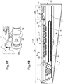
- the running board assembly I is in its so-called rest position, corresponding to normal rolling of the transport vehicle. In this position, the routing surface 90 of the pivoting floor 9 is flush with the fixed floor 104 of the body, the latter not being shown in this figure 17 .
- the various blades 8A to 8G of the sliding system 7 are received in the slide 36 of the intermediate device.
- these slats 8A to 8G extend below the reinforcement 91, provided on the underside of the movable floor.
- the guide rollers 87, belonging to these blades, bear against the side wall facing a respective slide 36.
- the aforementioned final blade 8H is for its part received in the transition 38, extending the slide 36, namely that this blade is positioned inclined upwards, in the direction of the outer spar 72.
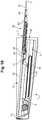
- the transport vehicle 100 is immobilized opposite a platform, illustrated schematically on the figure. figure 20 being designated as a whole by the reference 200.
- a platform illustrated schematically on the figure. figure 20 being designated as a whole by the reference 200.
- the surface of the platform is located below the upper surface of the movable floor 90.
- a sensor not shown then measures, in a manner known per se, the horizontal and vertical distances respectively separating the free edge 7 'of the sliding system, with respect to the end opposite the dock.
- a computer also not shown determines, from this measurement, the desired inclination of the sliding system, so that it comes to rest on the platform at the end of a deployment movement. It is also possible to provide that, at the end of this movement of deployment, the sliding system comes to rest, not on the platform, but opposite this platform and above the latter.
- each roller 58 provided at the end of a respective lever 57, is in engagement with a respective housing 22 and 24 of the framework. . It is then a question of starting the motor 4, so that the crown 49 drives the chain 51 and, consequently, the main shaft 5. As a result, each roller bears on the walls of a respective housing. . Thanks to the lever arm provided by the levers 57, this support of the roller drives the pivoting of the intermediate device 3 relative to the frame 1 around the characteristic axis A1, according to the arrow F3 on the figure 21 .
- the hook 17 is maintained in its active position.
- its end 19 makes it possible to support the pivoting floor 9, via the pin 98, as is shown in particular on the figure 5 . Consequently, this pivoting floor 9 is firmly held in position relative to the frame 1, even if it no longer bears on the intermediate device 3.
- the lug 35, carried by this intermediate device 3, is inactive. opposite the swivel floor. In other words, when this device 3 pivots downwards, this does not cause the member 9 to pivot.
- both of the intermediate device 3 and of the sliding system 7 the rotation of the main transmission shaft 5 is stopped. Then the toothed chains 43 are activated. and 44, so as to move the sliding system 7 in translation relative to the intermediate device 3.
- This translation which is shown on figure 22 by arrow F7, allows the free edge 7 'of the sliding system to bear against the upper surface of the dock 200, as illustrated in this same figure.
- the free edge of the sliding system can be located opposite the dock, above the upper surface of the latter.
- the single motor 4 performs several functions. This is first of all the drive of the shaft 5, via the crown 49 and the chain 51. An additional function resides in the drive of the sliding system 7, via the chains 43 and 44. Finally, the motor allows the driving of the levers 57, via the rod 60 as well as the connecting rods 62 and 63. In this regard, it will be noted that this characteristic is advantageous, in particular in terms of simplicity, insofar as a single motor assembly makes it possible to achieve these different functions.
- the distribution of the power generated by this engine, for the above functions, is advantageously managed by electric brakes or the like, which are mounted on various shafts located downstream of the engine. It will also be noted that the stability of the sliding system is obtained, advantageously by the fact that the latter is moved by means of an irreversible gear. Furthermore, the stability of the inclination of both the pivoting floor and of the intermediate device is also guaranteed thanks also to the use of an irreversible gear.
- the figures 24 to 27 further illustrate the tilting of the blades 8 during the translational movement of the sliding system relative to the intermediate device.
- all of the slats except the final slat are located below the reinforcement 61.
- the various blades also move relative to the latter according to the arrow F8 on the figures 24 and 25 .
- each guide roller 87 then bears against the side surface facing a respective slide 78, as shown in the figures. figures 25 and 26 .
- the figure 27 illustrates more clearly the position of the blades and of the carriages associated with them, both within the slide 36 and the slide 78. On this figure 27 , for the sake of clarity, these slides are not shown, their lower surface being materialized by dotted lines.
- the pivoting floor 9 is pivoted relative to the framework.
- the hook 17 is first unlocked by means of the actuator 23.
- the rod 60 is then moved and then, via the return disc 61, the connecting rods 62 and 63, according to the arrows F60, F61, F62 on the figure 26 .
- This causes a translational movement of the drums 56, according to the arrow F56 on the figure 8 , tending to extract the rollers 58 carried by the levers 57 out of the housings 22 and 24, according to the arrow F58 on the same figure 8 .
- This pivoting floor 9 is pivoted until it is in contact with the upper end of the sliding system.
- the slats 8D to 8H of the sliding system are located in the extension of the free edge 90 'of the routing surface 90.
- the figure 19 shows the formation of an access ramp belonging to the running board assembly according to the invention, which is designated as a whole by the reference 99.
- This ramp 99 is formed successively by the traveling surface 90, the slats 8D to 8H as well as the profiles 81 which separate them two by two, and finally by the spar 72.
- This characteristic makes it possible to ensure excellent continuity of surfaces between the floor and the sliding system, which is advantageous in particular in terms of comfort and safety, in particular for users in wheelchairs. Furthermore, it is possible to confer satisfactory mechanical properties on the floor 90, thanks to the presence of the reinforcement 91. It will be noted that this comfort and this safety are in particular allowed, without however compromising with the solidity, thanks to the fact that the slats of the sliding system tilt from the lower slide 36 in the direction of the upper slide 78, during the translation of the sliding system relative to the intermediate device.
- the figure 30 schematically summarizes the different steps, described above, allowing the deployment of the sliding system 7.
- the pivoting of the intermediate device downward according to the arrow F3 the translational movement of the sliding system 7 to the opposite of the intermediate device according to arrow F7, the unlocking of the hook 17 according to the arrow F17, the pivoting of the floor pivoting downward according to the arrow F9, then finally the opening of the door according to the arrow F106.
- these successive steps are assigned references O1 to O5, the letter “O” referring to this opening phase (“opening” in English).
- the figure 31 illustrates, analogously to what is shown on figure 28 , the steps allowing the folding of the sliding system 7, which are assigned references C1 to C4.
- the letter "C” refers to the closing phase.
- step C1 the pivoting of the intermediate device 3 upwards is accompanied by a corresponding pivoting of the pivoting floor 9.
- the lug 35 makes it possible to secure the pivoting floor with respect to this intermediate device.
- step C4 corresponding to the retraction of the pivoting floor, the movement of the blades and the carriages is the opposite of that described with reference to figure 25 .
- This reverse movement illustrated on figure 32 , involves an overall displacement of the blades 8 along the arrow F'8, as well as a sliding of the carriages along the cam 37, according to the arrows F'37, which induces a translation of these carriages towards the interior of the housings blades according to arrows F'87.
- the surface of the platform 200 is located above the upper surface of the movable floor 90.
- a sensor measures the distances between the free edge 7 'of the sliding system, relative to the end facing the dock.
- the computer mentioned above determines, from this measurement, the desired inclination of the sliding system. This inclination guarantees that, at the end of its movement of deployment, this sliding system comes to bear either on the quay, or opposite the quay slightly above it.
- the figure 33 illustrates, analogously to what is shown on figure 30 , the steps allowing the deployment of the sliding system 7 in this second possibility of implementation, these steps being assigned references O'1 to O'3.
- the letter "O" refers to the opening phase.
- the pivoting of the intermediate device upwards causes that of the pivoting floor, given the presence of the lug 35.
- the figure 34 illustrates, analogously to what is shown on figure 31 , the steps allowing the folding of the sliding system 7 in this second possibility of implementation, these steps being assigned references C'1 to C'3.
- the letter "C” refers to the closing phase.
- the invention provides numerous advantages with respect to the prior art mentioned in the preamble to the present description.
- the presence of the intermediate device 3 makes it possible to overcome the drawbacks, in terms of safety, linked to the teaching of EP 0 230 888 and FROM U 2010 4221 presented above.
- the movement of the sliding system can be dissociated from that of the walkway floor. Consequently, it is possible to move the sliding system, both in translation and in rotation, to its final position against the platform, while maintaining the floor in a position giving optimum safety to the passengers.
- the sliding system 7, comprising inter alia mutually articulated blades 8, is associated with the intermediate device 3.
- the intermediate device 3 provision can be made for these blades to be fitted to a set of step of a different type from that described and shown above.
- a step assembly can in particular be devoid of an intermediate device, such as that 3 which has been described above.
Landscapes
- Engineering & Computer Science (AREA)
- Mechanical Engineering (AREA)
- Life Sciences & Earth Sciences (AREA)
- Wood Science & Technology (AREA)
- Vehicle Step Arrangements And Article Storage (AREA)
- Seats For Vehicles (AREA)
- Body Structure For Vehicles (AREA)
Abstract
Cet ensemble comprend tout d'abord une ossature (1) fixée sur la caisse de ce véhicule, un plancher pivotant (9) destiné au cheminement des voyageurs, en particulier des personnes à mobilité réduite, et un dispositif intermédiaire (3), situé au-dessous de la surface de cheminement (90), le dispositif intermédiaire et le plancher pivotant (9) étant aptes à pivoter par rapport à l'ossature de manière mutuellement indépendante. Cet ensemble comprend en outre un système coulissant (7) mobile en translation par rapport au dispositif intermédiaire (3) entre une position repliée et une position dépliée, dans laquelle ce système coulissant forme, avec la surface de cheminement (90), une rampe (99) s'étendant au travers d'une ouverture latérale (20) de l'ossature.Grâce à l'invention, le mouvement du système coulissant peut être dissocié de celui du plancher de cheminement. Par conséquent il est possible de déplacer le système coulissant, à la fois en translation et en rotation, jusqu'à sa position finale contre le quai, tout en maintenant le plancher dans une position de sécurité optimale pour les passagers.This assembly firstly comprises a framework (1) fixed to the body of this vehicle, a pivoting floor (9) intended for the movement of travelers, in particular people with reduced mobility, and an intermediate device (3), located at the bottom. below the path surface (90), the intermediate device and the pivoting floor (9) being able to pivot relative to the frame in a mutually independent manner. This assembly further comprises a sliding system (7) movable in translation relative to the intermediate device (3) between a folded position and an unfolded position, in which this sliding system forms, with the path surface (90), a ramp ( 99) extending through a lateral opening (20) of the framework. Thanks to the invention, the movement of the sliding system can be dissociated from that of the walkway floor. Consequently, it is possible to move the sliding system, both in translation and in rotation, to its final position against the platform, while maintaining the floor in an optimum safety position for the passengers.
Description
La présente invention concerne un ensemble de marchepied, destiné à équiper un véhicule de transport. Elle concerne également un véhicule de transport, qui est équipé d'au moins un tel ensemble de marchepied. Elle concerne enfin un procédé de mise en œuvre de ce véhicule de transport, faisant en particulier intervenir un déploiement ou un repliement d'une rampe d'accès appartenant à cet ensemble de marchepied. La présente invention trouve son application à des véhicules de transport, notamment de type train, tramway, métro, trolleybus ou encore bus. Elle vise plus spécifiquement, mais non exclusivement, les trains transportant des personnes.The present invention relates to a step assembly, intended to equip a transport vehicle. It also relates to a transport vehicle, which is equipped with at least one such step assembly. Finally, it relates to a method of implementing this transport vehicle, in particular involving the deployment or folding of an access ramp belonging to this set of steps. The present invention finds its application to transport vehicles, in particular of the train, tram, metro, trolleybus or even bus type. It relates more specifically, but not exclusively, to trains transporting people.
De manière classique certains véhicules de transport sont équipés au moyen d'ensembles de marchepied, visant à faciliter l'accès des voyageurs. En effet les quais destinés à l'arrêt des véhicules puis à la montée et à la descente des voyageurs, ainsi que les planchers des véhicules, se situent souvent à des hauteurs différentes. Ces ensembles de marchepied comprennent en particulier un dispositif d'accès pour les utilisateurs, qui est mobile entre une position repliée et une position déployée.Conventionally, certain transport vehicles are equipped by means of footboard assemblies, aimed at facilitating passenger access. Indeed, the platforms intended for stopping vehicles and then getting on and off passengers, as well as the floors of vehicles, are often located at different heights. These step assemblies include in particular an access device for the users, which is movable between a folded position and a deployed position.
Il existe tout d'abord des ensembles de marchepied, dans laquelle ce dispositif est constitué d'une plaque mobile en rotation par rapport à la caisse du véhicule, le plus souvent autour de l'axe longitudinal de ce véhicule. Ainsi, dans sa position repliée, cette plaque est relevée de manière sensiblement verticale, au voisinage de la caisse. De tels ensembles de marchepied ne sont cependant pas ceux, qui sont concernés par la présente invention.First of all, there are running board assemblies, in which this device consists of a movable plate in rotation with respect to the body of the vehicle, most often around the longitudinal axis of this vehicle. Thus, in its folded position, this plate is raised substantially vertically, in the vicinity of the body. Such footboard assemblies are not, however, those which are concerned by the present invention.
En effet l'invention vise plus particulièrement des ensembles de marchepied, dans lesquels le dispositif d'accès est globalement mobile en translation. Ainsi, dans sa position repliée, elle se trouve escamotée en position sensiblement horizontale, au voisinage du plancher fixe appartenant à la caisse du véhicule. Par ailleurs, dans sa position dépliée, son extrémité libre peut prendre généralement appui sur le quai ou rester en porte-à-faux.In fact, the invention relates more particularly to footboard assemblies, in which the access device is generally mobile in translation. Thus, in its folded position, it is retracted into a substantially horizontal position, in the vicinity of the fixed floor belonging to the body of the vehicle. Moreover, in its unfolded position, its free end can generally rest on the platform or remain cantilevered.
On connaît tout d'abord des véhicules de transport, qui sont équipés au moyen d'une plaque coulissante susceptible de se déployer en translation par rapport à la caisse, typiquement selon un mouvement horizontal. Cette plaque permet certes de combler la lacune horizontale, existant entre le quai et la porte. Néanmoins, étant donné que cette plaque se déploie selon un mouvement dont l'inclinaison n'est pas variable, cette solution ne permet pas une adaptation à des quais de hauteurs différentes.Firstly, transport vehicles are known, which are equipped by means of a sliding plate capable of deploying in translation with respect to the body, typically in a horizontal movement. This plate certainly makes it possible to fill the horizontal gap existing between the platform and the door. However, given that this plate is deployed according to a movement the inclination of which is not variable, this solution does not allow adaptation to platforms of different heights.
Afin de remédier à cet inconvénient, on a proposé d'équiper les véhicules de transport au moyen d'une rampe inclinable. En pratique, cette rampe se déplace par rapport à la caisse selon un mouvement de translation, dont l'inclinaison finale dépend de la différence de hauteurs entre le quai et le plancher du véhicule. Cette solution permet, du moins en théorie, de résoudre le problème lié à l'utilisation des plaques coulissantes ci-dessus.In order to remedy this drawback, it has been proposed to equip transport vehicles by means of a tilting ramp. In practice, this ramp moves relative to the body according to a translational movement, the final inclination of which depends on the difference in heights between the platform and the floor of the vehicle. This solution makes it possible, at least in theory, to solve the problem associated with the use of the above sliding plates.
Elle implique cependant d'autres inconvénients, en particulier lorsque la différence de hauteurs entre la caisse et le quai est importante. En effet, dans cette configuration, la rampe inclinable présente une pente élevée. Cela n'est pas satisfaisant, notamment en vue d'un accès commode et sécurisé pour des personnes à mobilité réduite (ou PMR). Cette désignation englobe non seulement les personnes en situation de handicap permanent, par exemple en fauteuil roulant ou étant aveugles, mais également les voyageurs ayant une diminution temporaire des capacités de déplacement dans l'espace public, par exemple des voyageurs transportant des bagages volumineux ou encore des femmes enceintes.However, it involves other drawbacks, in particular when the difference in heights between the body and the dock is significant. In fact, in this configuration, the tilting ramp has a high slope. This is not satisfactory, particularly with a view to convenient and secure access for people with reduced mobility (or PRM). This designation encompasses not only people with a permanent disability, for example in a wheelchair or who are blind, but also travelers with a temporary reduction in their ability to move around in public spaces, for example travelers carrying bulky luggage or even pregnant women.
Afin de conférer une faible pente à cette rampe inclinable, on peut certes envisager de la réaliser avec une grande longueur. Cette alternative n'est pas non plus satisfaisante, notamment en ce que cette rampe présente alors un encombrement horizontal, sur le quai, générant beaucoup d'interférences avec les voyageurs attendant sur ce quai. Par conséquent sa mise en mouvement, en particulier de manière automatique, est dans ce cas particulièrement contraignante en pratique.In order to give a low slope to this tilting ramp, it is certainly possible to envisage making it with a great length. This alternative is not satisfactory either, in particular in that this ramp then has a horizontal footprint on the platform, generating a great deal of interference with travelers waiting on this platform. Consequently, its setting in motion, in particular automatically, is in this case particularly restrictive in practice.
On connaît encore d'autres solutions, dans lesquelles la caisse du véhicule est équipée d'une plate-forme située à proximité des portes et mobile verticalement par rapport au plancher fixe. Une fois que la plate-forme est placée à la même hauteur que le quai, il est alors possible de déployer un dispositif classique (ou marchepied) d'accès pour les passagers. Parmi les brevets antérieurs décrivant une telle plate-forme mobile, on citera notamment
Cette solution alternative présente également certains inconvénients spécifiques, notamment en termes de sécurité. En effet, dans le cas où la plate-forme possède un marchepied dépliable intégré à l'intérieur de la caisse, la lacune horizontale n'est pas comblée avant l'ouverture des portes qui est requise pour pouvoir sortir le marchepied si celui-ci est en retrait du vantail. Même lorsque le marchepied est situé au-dessous du ou des vantaux de porte, cela crée une ouverture béante entre la plateforme abaissée et le(s) vantail (vantaux) de la porte opposée. Dans ces deux cas, ces inconvénients sont à proscrire car ils impliquent des risques de chutes d'objets, voire de passagers sur la voie.This alternative solution also has certain specific drawbacks, in particular in terms of security. Indeed, in the event that the platform has a fold-out step integrated inside the body, the horizontal gap is not filled before the doors are opened, which is required to be able to remove the step if it is set back from the leaf. Even when the step is located below the door leaf (s), it creates a gaping opening between the lowered platform and the door leaf (s) of the opposite door. In these two cases, these drawbacks should be avoided because they involve the risk of falling objects, or even passengers on the track.
Enfin on connaît, notamment par le brevet européen
Cette dernière solution ne se révèle pas totalement satisfaisante. En effet, un inconvénient de ce dispositif réside dans la connexion mécanique entre le(les) vantail (vantaux) de porte et la plate-forme inclinée. En effet, cette plate-forme ne peut commencer à être inclinée avant l'ouverture de la porte, puisque cela crée un espace entre la plate-forme et le panneau de porte, lequel est préjudiciable en termes de sécurité. De surcroît, si on incline le dispositif après le déploiement de la plaque coulissante, on peut blesser les pieds des passagers présents sur les quais.This latter solution does not prove to be completely satisfactory. Indeed, a drawback of this device lies in the mechanical connection between the door leaf (s) and the inclined platform. Indeed, this platform cannot start to be inclined before the opening of the door, since this creates a space between the platform and the door panel, which is detrimental in terms of safety. In addition, if the device is tilted after the sliding plate has been deployed, the feet of passengers on the platforms can be injured.
Compte tenu de ce qui précède, un objectif de la présente invention est de remédier, au moins partiellement, aux inconvénients de l'art antérieur évoqués ci-dessus.In view of the above, an objective of the present invention is to remedy, at least partially, the drawbacks of the prior art mentioned above.
Un autre objectif de l'invention est de proposer un ensemble de marchepied qui permet d'assurer un accès commode et sécurisé aux voyageurs utilisant des quais, destinés à l'arrêt du véhicule, qui présentent des altitudes assez différentes.Another objective of the invention is to provide a set of steps which make it possible to provide convenient and secure access to travelers using platforms, intended for stopping the vehicle, which have quite different altitudes.
Un autre objectif de l'invention est en particulier de proposer un tel ensemble de marchepied, dont la mise en œuvre ne crée aucune lacune spatiale, susceptible d'engendrer un danger, notamment un risque de chute.Another objective of the invention is in particular to provide such a set of steps, the implementation of which does not create any space gap, liable to generate a danger, in particular a risk of falling.
Un autre objectif de l'invention est de proposer un tel ensemble de marchepied, possédant une rampe dépliable qui se prête tout particulièrement à l'accès aux personnes à mobilité réduite, en termes de confort et de sécurité.Another objective of the invention is to provide such a set of steps, having an unfolding ramp which is particularly suitable for access to people with reduced mobility, in terms of comfort and safety.
Selon l'invention, au moins un des objectifs ci-dessus est atteint au moyen d'un premier objet principal de l'invention, qui est un ensemble de marchepied (l, l') pour véhicule de transport (100), notamment du type train, tramway, métro, bus ou encore trolleybus, cet ensemble comprenant
- une ossature (1) comportant des moyens de fixation (26, 28) sur la caisse (102) du véhicule de transport, cette ossature délimitant une ouverture latérale (20),
- un plancher pivotant (9), situé en service à proximité de la porte (106) du véhicule de transport, ce plancher pivotant étant destiné au cheminement des voyageurs, en particulier des personnes à mobilité réduite, ce plancher pivotant comprenant une surface (90) de cheminement et étant monté de manière pivotante par rapport à l'ossature autour d'un premier axe de pivotement (A1), prévu à l'opposé de ladite ouverture latérale (20),
- un dispositif intermédiaire (3), situé au-dessous de la surface de cheminement (90), ce dispositif intermédiaire étant monté de manière pivotante par rapport à l'ossature autour d'un second axe de pivotement (A1), qui est notamment confondu avec le premier axe de pivotement, le dispositif intermédiaire et le plancher pivotant (9) étant aptes à pivoter par rapport à l'ossature de manière mutuellement indépendante,
- un système coulissant (7) mobile en translation par rapport au dispositif intermédiaire (3) entre une position repliée et une position dépliée, dans laquelle ce système coulissant forme, avec la surface de cheminement (90), une rampe (99) s'étendant au travers de ladite ouverture latérale (20).
- a framework (1) comprising fixing means (26, 28) on the body (102) of the transport vehicle, this framework defining a lateral opening (20),
- a pivoting floor (9), located in service near the door (106) of the transport vehicle, this pivoting floor being intended for the movement of travelers, in particular people with reduced mobility, this pivoting floor comprising a surface (90) tracking and being mounted so as to pivot with respect to the framework about a first pivot axis (A1), provided opposite to said lateral opening (20),
- an intermediate device (3), located below the path surface (90), this intermediate device being mounted so as to pivot relative to the framework about a second pivot axis (A1), which is in particular coincident with the first pivot axis, the intermediate device and the pivoting floor (9) being able to pivot relative to the frame in a mutually independent manner,
- a sliding system (7) movable in translation with respect to the intermediate device (3) between a folded position and an unfolded position, in which this sliding system forms, with the path surface (90), a ramp (99) extending through said lateral opening (20).
Selon d'autres caractéristiques du premier objet principal de l'invention ci-dessus, prises individuellement ou selon toute combinaison techniquement compatible :
- cet ensemble comprend des premiers moteurs (4) et des premiers moyens de transmission (5, 56, 57, 58, 24) permettant le pivotement du dispositif intermédiaire, ainsi que des seconds moyens moteurs (4) et des seconds moyens de transmission (5, 56, 57, 58, 97) permettant le pivotement du plancher pivotant.
- Les premiers moyens moteurs et les seconds moyens moteurs sont formés par un unique ensemble moteur (4) apte à coopérer respectivement avec les premiers moyens de transmission et les seconds moyens de transmission.
- Cet ensemble comprend en outre des moyens de sélection qui présentent une première configuration fonctionnelle dans laquelle ils assurent le pivotement du dispositif intermédiaire (3), ainsi qu'une seconde configuration fonctionnelle dans laquelle ils assurent le pivotement du plancher pivotant (9).
- Ces moyens de sélection comprennent un levier (57) terminé par un galet (58), ce levier étant apte à être entraîné par un arbre de transmission (5), le galet étant apte à coopérer sélectivement soit avec un premier organe de transmission (22, 24), soit avec un second organe de transmission (97).
- Le premier organe de transmission comprend un logement (22, 24) solidaire de l'ossature, le galet (58) étant apte à rouler le long des parois de ce logement de manière à assurer le pivotement du dispositif intermédiaire, par l'intermédiaire de l'effet procuré par le levier, alors que le second organe de transmission comprend un organe d'appui (97) solidaire du plancher pivotant (9), cet organe d'appui étant apte à coopérer avec le galet (58).
- Cet ensemble comprend en outre des moyens (52, 75) d'entraînement du système coulissant (7) par rapport au dispositif intermédiaire (3), ces moyens d'entraînement étant notamment aptes à coopérer avec les premiers moyens moteurs ou les seconds moyens moteurs, ces moyens d'entraînement du système coulissant (7) comprenant en particulier au moins une chaîne (52) ou une courroie, apte à être entraînée par les premiers moyens moteurs ou les seconds moyens moteurs, ainsi qu'au moins un connecteur mécanique respectif (75), apte à solidariser la chaîne avec le système coulissant.
- Cet ensemble comprend en outre des moyens (17) de verrouillage du plancher pivotant (9) par rapport à l'ossature (1), qui sont mobiles entre une position active dans laquelle ils verrouillent le plancher pivotant par rapport à l'ossature, ainsi qu'une position inactive dans laquelle ils libèrent le plancher pivotant par rapport à l'ossature, de manière à permettre le pivotement de ce plancher pivotant sous l'effet des seconds moyens moteurs.
- Cet ensemble comprend en outre des moyens (35) de solidarisation du plancher pivotant (9) par rapport au dispositif intermédiaire (3), lesquels sont aptes à solidariser mutuellement ce plancher pivotant et ce dispositif intermédiaire, uniquement lors de leurs déplacements vers le haut.
- Le système coulissant (7) comprend une succession de lames (8) mobiles perpendiculairement à leur dimension principale, ces lames étant mutuellement parallèles et étant en outre parallèles en service à l'axe de roulage du véhicule.
- Le dispositif intermédiaire (3) comprend une première piste (36) de déplacement des lames, perpendiculairement à leur dimension principale, alors que le système coulissant (7) comprend une autre piste (78) de déplacement des lames, l'ensemble comprenant des moyens de basculement des lames entre ces pistes, les moyens de basculement comprenant notamment au moins un chariot (85) reliant deux lames adjacentes, chaque chariot étant propre à prendre appui contre la paroi latérale de chaque glissière, deux chariots (85) associés à chaque couple de lames adjacentes étant avantageusement prévus, chacun à une extrémité respective des lames, ces deux chariots étant mobiles l'un à l'opposé de l'autre, notamment sous l'effet de moyens élastiques (88).
- this assembly comprises first motors (4) and first transmission means (5, 56, 57, 58, 24) allowing the pivoting of the intermediate device, as well as second motor means (4) and second transmission means (5 , 56, 57, 58, 97) allowing the pivoting of the pivoting floor.
- The first motor means and the second motor means are formed by a single motor assembly (4) capable of cooperating respectively with the first transmission means and the second transmission means.
- This assembly further comprises selection means which have a first functional configuration in which they ensure the pivoting of the intermediate device (3), as well as a second functional configuration in which they ensure the pivoting of the pivoting floor (9).
- These selection means comprise a lever (57) terminated by a roller (58), this lever being able to be driven by a transmission shaft (5), the roller being able to cooperate selectively either with a first transmission member (22 , 24), or with a second transmission member (97).
- The first transmission member comprises a housing (22, 24) integral with the framework, the roller (58) being able to roll along the walls of this housing so as to ensure the pivoting of the intermediate device, by means of the effect provided by the lever, while the second transmission member comprises a support member (97) integral with the pivoting floor (9), this support member being able to cooperate with the roller (58).
- This assembly further comprises means (52, 75) for driving the sliding system (7) relative to the intermediate device (3), these drive means being in particular able to cooperate with the first motor means or the second motor means. , these drive means of the sliding system (7) comprising in particular at least one chain (52) or a belt, able to be driven by the first drive means or the second drive means, as well as at least one respective mechanical connector (75), suitable for securing the chain with the sliding system.
- This assembly further comprises means (17) for locking the pivoting floor (9) relative to the frame (1), which are movable between an active position in which they lock the pivoting floor relative to the frame, thus an inactive position in which they release the pivoting floor relative to the framework, so as to allow the pivoting of this pivoting floor under the effect of the second motor means.
- This assembly further comprises means (35) for securing the pivoting floor (9) relative to the intermediate device (3), which are capable of mutually securing this pivoting floor and this intermediate device, only during their upward movements.
- The sliding system (7) comprises a succession of blades (8) movable perpendicularly to their main dimension, these blades being mutually parallel and also being parallel in service to the rolling axis of the vehicle.
- The intermediate device (3) comprises a first track (36) for moving the blades, perpendicular to their main dimension, while the sliding system (7) comprises another track (78) for moving the blades, the assembly comprising means for tilting the blades between these tracks, the tilting means comprising in particular at least one carriage (85) connecting two adjacent blades, each carriage being able to bear against the side wall of each slide, two carriages (85) associated with each pair adjacent blades being advantageously provided, each at a respective end of the blades, these two carriages being movable one opposite the other, in particular under the effect of elastic means (88).
Un deuxième objet principal de l'invention est un véhicule de transport (100), notamment du type train, tramway, métro, bus ou encore trolleybus, comprenant au moins un ensemble de marchepied (l, l') tel que défini ci-dessus.A second main object of the invention is a transport vehicle (100), in particular of the train, tram, metro, bus or even trolleybus type, comprising at least one set of steps (l, l ') as defined above. .
Selon d'autres caractéristiques de ce deuxième objet principal de l'invention, prises individuellement ou selon toute combinaison techniquement compatible :
- la caisse (102) de ce véhicule de transport comprend un plancher dit fixe (104), la surface de cheminement (90) du plancher pivotant (9) étant située dans le même plan que le plancher fixe, dans une position dite de repos du plancher pivotant, alors que le plancher fixe et la surface de cheminement définissent une continuité de surfaces, c'est-à-dire sans ressaut significatif, dans une position inclinée de ce plancher pivotant par rapport au plancher fixe ;
- chaque ensemble de marchepied s'étend sur une partie seulement de la largeur de la caisse, en particulier sensiblement sur la moitié de cette largeur ;
- ce véhicule comprend deux ensembles de marchepied (l, l') disposés de part et d'autre de la direction transversale de la caisse, les axes de pivotement (A1, A1') de ces ensembles s'étendant à proximité immédiate de l'autre.
- the body (102) of this transport vehicle comprises a said fixed floor (104), the running surface (90) of the pivoting floor (9) being located in the same plane as the fixed floor, in a so-called rest position of the pivoting floor, while the fixed floor and the movement surface define a continuity of surfaces, that is to say without significant projection, in an inclined position of this pivoting floor relative to the fixed floor;
- each running board assembly extends over only part of the width of the body, in particular substantially over half of this width;
- this vehicle comprises two sets of running boards (l, l ') arranged on either side of the transverse direction of the body, the pivot axes (A1, A1') of these sets extending in the immediate vicinity of the other.
Un troisième objet principal de l'invention est un procédé de mise en œuvre d'un véhicule de transport (100) tel que ci-dessus, dans lequel le plancher fixe (104) de la caisse est situé au-dessus d'un quai (200) de débarquement des voyageurs, ce procédé comprenant les étapes suivantes, dans la séquence d'ouverture de la porte de ce véhicule :
- pivotement du dispositif intermédiaire (3) vers le bas, par rapport à l'ossature (flèche F3),
- déplacement en translation du système coulissant (7) à l'opposé du dispositif intermédiaire (flèche F7)
- pivotement du plancher pivotant vers le bas (flèche F9),
- ouverture de la porte (106) (flèche F106).
- pivoting of the intermediate device (3) downwards, relative to the framework (arrow F3),
- translational movement of the sliding system (7) away from the intermediate device (arrow F7)
- downward pivoting of the pivoting floor (arrow F9),
- opening of the door (106) (arrow F106).
Ce procédé peut en outre avantageusement comprendre une étape de déverrouillage (flèche F17) de l'organe de verrouillage (17), entre le déplacement en translation du système coulissant et le pivotement du plancher pivotant vers le bas.This method can also advantageously comprise a step of unlocking (arrow F17) of the locking member (17), between the translational movement of the sliding system and the pivoting of the pivoting floor downward.
Ce procédé peut en outre avantageusement comprendre les étapes suivantes, dans la séquence de fermeture de la porte :
- pivotement du plancher pivotant (9) vers le haut
- fermeture de la porte
- escamotage du plancher pivotant par rapport au dispositif intermédiaire.
- swiveling of the pivoting floor (9) upwards
- closing the door
- retraction of the pivoting floor relative to the intermediate device.
Ce procédé peut en outre avantageusement comprendre une étape de verrouillage de l'organe de verrouillage entre le pivotement du plancher pivotant et la fermeture de la porte.This method can also advantageously comprise a step of locking the locking member between the pivoting of the pivoting floor and the closing of the door.
Un quatrième objet principal de l'invention est un procédé de mise en œuvre d'un véhicule de transport tel que ci-dessus, dans lequel le plancher fixe de la caisse est situé au-dessous d'un quai de débarquement des voyageurs, ce procédé comprenant les étapes suivantes, dans la séquence d'ouverture de la porte du véhicule :
- déplacement en translation du système coulissant (7) à l'opposé du dispositif intermédiaire
- ouverture de la porte
- pivotement simultané vers le haut du dispositif intermédiaire et du plancher pivotant.
- translational movement of the sliding system (7) away from the intermediate device
- door opening
- simultaneous upward pivoting of the intermediate device and the pivoting floor.
Ce procédé peut en outre avantageusement comprendre les étapes suivantes, dans la séquence de fermeture de la porte de véhicule :
- pivotement simultané vers le bas du dispositif intermédiaire et du plancher pivotant,
- fermeture de la porte
- déplacement en translation du système coulissant (7) vers le dispositif intermédiaire.
- simultaneous downward pivoting of the intermediate device and the pivoting floor,
- closing the door
- translational movement of the sliding system (7) towards the intermediate device.
Un cinquième objet principal de l'invention est un ensemble de marchepied pour véhicule de transport, notamment du type train, tramway, métro, bus ou encore trolleybus, cet ensemble comprenant
- une ossature comportant des moyens de fixation sur la caisse du véhicule de transport,
- un dispositif coulissant mobile par rapport à l'ossature entre une position repliée et une position dépliée, dans laquelle ce dispositif coulissant forme au moins une partie d'une rampe d'accès,
- a framework comprising means for fixing to the body of the transport vehicle,
- a sliding device movable relative to the framework between a folded position and an unfolded position, in which this sliding device forms at least part of an access ramp,
Selon d'autres caractéristiques de ce cinquième objet principal de l'invention, prises individuellement ou selon toute combinaison techniquement compatible :
- il est prévu une première piste (36) de déplacement des lames, ainsi qu'une autre piste (78) de déplacement des lames, l'ensemble comprenant des moyens de basculement des lames entre ces pistes ;
- les moyens de basculement comprennent notamment au moins un chariot (85) reliant deux lames adjacentes, chaque chariot étant propre à prendre appui contre la paroi latérale de chaque glissière ;
- deux chariots (85) associés à chaque couple de lames adjacentes sont prévus, chacun à une extrémité respective des lames, ces deux chariots étant mobiles l'un à l'opposé de l'autre, notamment sous l'effet de moyens élastiques (88) ;
- ledit ensemble de marchepied comprend en outre un plancher pivotant situé en service à proximité de la porte du véhicule de transport, ce plancher pivotant étant destiné au cheminement des voyageurs, en particulier des personnes à mobilité réduite, ce plancher pivotant comprenant une surface de cheminement.
- there is provided a first track (36) for moving the blades, as well as another track (78) for moving the blades, the assembly comprising means for tilting the blades between these tracks;
- the tilting means comprise in particular at least one carriage (85) connecting two adjacent blades, each carriage being able to bear against the side wall of each slide;
- two carriages (85) associated with each pair of adjacent blades are provided, each at a respective end of the blades, these two carriages being movable one opposite the other, in particular under the effect of elastic means (88 );
- said step assembly further comprises a pivoting floor located in service near the door of the transport vehicle, this pivoting floor being intended for the movement of travelers, in particular people with reduced mobility, this pivoting floor comprising a movement surface.
Un sixième objet principal de l'invention est un véhicule de transport, notamment du type train, tramway, métro, bus ou encore trolleybus, comprenant au moins un ensemble de marchepied tel que défini immédiatement ci-dessus, ledit ensemble de marchepied comprenant en outre un plancher pivotant situé en service à proximité de la porte du véhicule de transport, ce plancher pivotant étant destiné au cheminement des voyageurs, en particulier des personnes à mobilité réduite, ce plancher pivotant comprenant une surface de cheminement,
la caisse de ce véhicule de transport comprenant un plancher dit fixe, la surface de cheminement du plancher pivotant étant située dans le même plan que le plancher fixe, dans une position dite de repos du plancher pivotant, alors que le plancher fixe et la surface de cheminement définissent une continuité de surfaces, c'est-à-dire sans ressaut significatif, dans une position inclinée de ce plancher pivotant par rapport au plancher fixe.A sixth main object of the invention is a transport vehicle, in particular of the train, tram, metro, bus or even trolleybus type, comprising at least one set of steps as defined immediately above, said set of steps further comprising a pivoting floor located in service near the door of the transport vehicle, this pivoting floor being intended for the movement of travelers, in particular people with reduced mobility, this pivoting floor comprising a movement surface,
the body of this transport vehicle comprising a so-called fixed floor, the running surface of the pivoting floor being located in the same plane as the fixed floor, in a so-called rest position of the pivoting floor, while the fixed floor and the surface of routing define a continuity of surfaces, that is to say without significant projection, in an inclined position of this pivoting floor relative to the fixed floor.
L'invention va être décrite ci-après, en référence aux dessins annexés, donnés uniquement à titre d'exemples non limitatifs, dans lesquels :
- [
Fig. 1 ] est une vue de dessus, illustrant de manière schématique une partie d'un véhicule de transport équipé de deux ensembles de marchepied conformes à l'invention. - [
Fig. 2 ] est une vue en perspective, illustrant à plus grande échelle un des deux ensembles de marchepied de lafigure 1 . - [
Fig. 3 ] est une vue en perspective, illustrant de manière séparée une ossature appartenant à l'ensemble de marchepied de lafigure 2 . - [
Fig. 4 ] est une vue en perspective, illustrant de manière isolée un crochet de verrouillage, appartenant à l'ossature de lafigure 3 . - [
Fig. 5 ] est une vue en perspective, illustrant sous un autre angle le crochet de lafigure 4 , dans une position où il permet le verrouillage du plancher mobile et des pièces environnantes par rapport à l'ossature, appartenant à l'ensemble de marchepied selon l'invention. - [
Fig. 6 ] est une vue en perspective illustrant, depuis l'extérieur de l'ossature, le crochet desfigures 4 , ainsi qu'un actionneur de ce crochet.et 5 - [
Fig. 7 ] est une vue en perspective, illustrant de manière séparée un dispositif intermédiaire appartenant à l'ensemble de marchepied des figures précédentes. - [
Fig. 8 ] est une vue en perspective illustrant, à plus grande échelle, l'extrémité d'un arbre de transmission appartenant au dispositif intermédiaire de lafigure 7 , ainsi qu'un levier coopérant avec cet arbre. - [
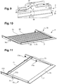
Fig. 9 ] est une vue en perspective illustrant, de manière isolée, une glissière ménagée dans un flanc du dispositif intermédiaire desfigures 7 et 8 . - [
Fig. 10 ] est une vue en perspective, illustrant de manière séparée un système coulissant appartenant à l'ensemble de marchepied des figures précédentes. - [
Fig. 11 ] est une vue en perspective, illustrant un cadre appartenant au système coulissant de lafigure 10 . - [
Fig. 12 ] est une vue en perspective illustrant, sous un angle différent de celui desfigures 10 , le cadre de laet 11figure 11 monté sur le dispositif intermédiaire de lafigure 7 . - [
Fig. 13 ] est une vue en perspective illustrant, de manière isolée, une glissière ménagée dans le cadre desfigures 11 et 12 . - [
Fig. 14 ] est une vue en perspective, illustrant de manière séparée une succession de lames appartenant au système coulissant de lafigure 10 . - [
Fig. 15 ] est une vue en coupe, prise selon l'axe principal d'un arbre appartenant au dispositif intermédiaire, illustrant en particulier les glissières équipant ce dispositif intermédiaire et le système coulissant, appartenant à l'ensemble de marchepied conforme à l'invention. - [
Fig. 16 ] est une vue en perspective, illustrant de manière séparée un plancher pivotant appartenant à l'ensemble de marchepied conformes à l'invention. - [
Fig. 17 ] est une vue en perspective, illustrant de manière isolée un patin d'appui, appartenant au plancher pivotant de lafigure 16 . - [
Fig. 18 ] est une vue en coupe longitudinale, illustrant l'ensemble de marchepied conforme à l'invention dans la position repliée de son système coulissant, avec toutes les parties inclinables positionnées de manière horizontale. - [
Fig. 19 ] est une vue en coupe longitudinale, illustrant l'ensemble de marchepied conforme à l'invention dans la position dépliée de son système coulissant, avec toutes les parties inclinables positionnées de manière inclinée par rapport à l'horizontale. - [
Fig. 20 ] est une vue de côté, illustrant un véhicule de transport équipé avec un ensemble de marchepied selon l'invention, en regard d'un quai dont l'altitude est inférieure à celle du plancher fixe de ce véhicule. - [
Fig. 21 ] est une vue de côté, analogue à lafigure 20 , illustrant une première étape de la mise en œuvre de ce véhicule. - [
Fig. 22 ] est une vue de côté, analogue auxfigures 20 , illustrant une seconde étape de cette mise en œuvre.et 21 - [
Fig. 23 ] est une vue de côté, analogue auxfigures 20 à 22 , illustrant une troisième étape de cette mise en œuvre. - [
Fig. 24 ] est une vue en perspective, illustrant le positionnement des lames du système coulissant, le long des glissières appartenant au dispositif intermédiaire et au système coulissant. - [
Fig. 25 ] est une vue de dessus, illustrant le mouvement des lames de lafigure 24 lors de leur passage depuis la glissière inférieure vers la glissière supérieure. - [
Fig. 26 ] est une vue en perspective, illustrant le positionnement des lames dans la glissière supérieure. - [
Fig. 27 ] est une vue en perspective, illustrant sous un autre angle la plus grande échelle, le positionnement des lames le long de cette glissière. - [
Fig. 28 ] est une vue en perspective, illustrant le déplacement de tringles et de bielles appartenant au dispositif intermédiaire. - [
Fig. 29 ] est une vue en perspective, illustrant le système coulissant dans sa position déployée par rapport au dispositif intermédiaire. - [
Fig. 30 ] est une vue schématique, récapitulant les différentes étapes mises en œuvre lors du déploiement du système coulissant, lorsque le quai en regard est situé à une altitude inférieure à celle du plancher fixe du véhicule. - [
Fig. 31 ] est une vue schématique, récapitulant les différentes étapes mises en œuvre lors du repliement du système coulissant de lafigure 30 . - [
Fig. 32 ] est une vue de dessus, analogue à lafigure 25 , montrant le déplacement des lames lors de cette phase de repliement. - [
Fig. 33 ] est une vue schématique, récapitulant les différentes étapes mises en œuvre lors du déploiement du système coulissant, lorsque le quai en regard est situé à une altitude supérieure à celle du plancher fixe du véhicule. - [
Fig. 34 ] est une vue schématique, récapitulant les différentes étapes mises en œuvre lors du repliement du système coulissant de lafigure 33 .
- [
Fig. 1 ] is a top view, schematically illustrating a part of a transport vehicle equipped with two sets of footboards according to the invention. - [
Fig. 2 ] is a perspective view, illustrating on a larger scale one of the two sets of steps of thefigure 1 . - [
Fig. 3 ] is a perspective view, separately illustrating a frame belonging to the footboard assembly of thefigure 2 . - [
Fig. 4 ] is a perspective view, illustrating in isolation a locking hook, belonging to the framework of thefigure 3 . - [
Fig. 5 ] is a perspective view, showing from another angle the hook of thefigure 4 , in a position where it allows the locking of the movable floor and the surrounding parts relative to the framework, belonging to the step assembly according to the invention. - [
Fig. 6 ] is a perspective view showing, from the outside of the framework, the hook of thefigures 4 and 5 , as well as an actuator for this hook. - [
Fig. 7 ] is a perspective view, separately illustrating an intermediate device belonging to the step assembly of the preceding figures. - [
Fig. 8 ] is a perspective view illustrating, on a larger scale, the end of a transmission shaft belonging to the intermediate device of thefigure 7 , as well as a lever cooperating with this shaft. - [
Fig. 9 ] is a perspective view illustrating, in isolation, a slide formed in a side of the intermediate device of thefigures 7 and8 . - [
Fig. 10 ] is a perspective view, separately illustrating a sliding system belonging to the step assembly of the preceding figures. - [
Fig. 11 ] is a perspective view, illustrating a frame belonging to the sliding system of thefigure 10 . - [
Fig. 12 ] is a perspective view showing, from a different angle than thefigures 10 and 11 , part of thefigure 11 mounted on the intermediate device of thefigure 7 . - [
Fig. 13 ] is a perspective view illustrating, in isolation, a slide formed within the framework of thefigures 11 and12 . - [
Fig. 14 ] is a perspective view, separately illustrating a succession of slats belonging to the sliding system of thefigure 10 . - [
Fig. 15 ] is a sectional view, taken along the main axis of a shaft belonging to the intermediate device, illustrating in particular the slides fitted to this intermediate device and the sliding system, belonging to the running board assembly according to the invention. - [
Fig. 16 ] is a perspective view, separately illustrating a pivoting floor belonging to the step assembly according to the invention. - [
Fig. 17 ] is a perspective view, illustrating in isolation a support pad, belonging to the pivoting floor of thefigure 16 . - [
Fig. 18 ] is a longitudinal sectional view, illustrating the step assembly according to the invention in the folded position of its sliding system, with all the tilting parts positioned horizontally. - [
Fig. 19 ] is a longitudinal sectional view, illustrating the step assembly according to the invention in the unfolded position of its sliding system, with all the tilting parts positioned inclined relative to the horizontal. - [
Fig. 20 ] is a side view, illustrating a transport vehicle equipped with a step assembly according to the invention, facing a platform whose altitude is lower than that of the fixed floor of this vehicle. - [
Fig. 21 ] is a side view, analogous to thefigure 20 , illustrating a first step in the implementation of this vehicle. - [
Fig. 22 ] is a side view, analogous tofigures 20 and 21 , illustrating a second stage of this implementation. - [
Fig. 23 ] is a side view, analogous tofigures 20 to 22 , illustrating a third stage of this implementation. - [
Fig. 24 ] is a perspective view, illustrating the positioning of the slats of the sliding system, along the slides belonging to the intermediate device and to the sliding system. - [
Fig. 25 ] is a top view, illustrating the movement of the blades of thefigure 24 during their passage from the lower slide to the upper slide. - [
Fig. 26 ] is a perspective view, illustrating the positioning of the blades in the upper slide. - [
Fig. 27 ] is a perspective view, illustrating from another angle the larger scale, the positioning of the blades along this slide. - [
Fig. 28 ] is a perspective view illustrating the movement of rods and connecting rods belonging to the intermediate device. - [
Fig. 29 ] is a perspective view illustrating the sliding system in its deployed position relative to the intermediate device. - [
Fig. 30 ] is a schematic view, recapitulating the various steps implemented during the deployment of the sliding system, when the platform opposite is located at an altitude lower than that of the fixed floor of the vehicle. - [
Fig. 31 ] is a schematic view, summarizing the different steps implemented during the folding of the sliding system of thefigure 30 . - [
Fig. 32 ] is a top view, analogous to thefigure 25 , showing the movement of the blades during this folding phase. - [
Fig. 33 ] is a schematic view, recapitulating the various steps implemented during the deployment of the sliding system, when the platform opposite is located at an altitude higher than that of the fixed floor of the vehicle. - [
Fig. 34 ] is a schematic view, summarizing the different steps implemented during the folding of the sliding system of thefigure 33 .
Les références numériques suivantes sont utilisées dans la présente description. l et l' ensembles de marchepied
- XX :
- axe de roulage
- 100 :
- véhicule de transport
- 102 :
- caisse du véhicule
- 104 :
- plancher fixe de la caisse
- 106 et 108 :
- portes
- 110 :
- renfoncement
- 1 :
- ossature
- 10 :
fond de 1- 11 :
- axe physique de pivotement
- 12 :
- aile intérieure
- 14 :
- œillets
- 16 et 18 :
- flancs
- 20 :
- ouverture latérale
- 22 et 24 :
- logements
- 26 et 28 :
- rives
- 17 :
- crochet de verrouillage
- 19 :
- extrémité de verrouillage
- 21 :
- échancrure dans le flanc 16
- 23 :
- actionneur de 17
- 3 :
- dispositif intermédiaire pivotant
- 30 :
- fond
- 31 :
- aile
- 32 :
- œillets
- 33 et 34 :
- flancs
- 35 :
- ergot
- 36 :
- glissière basse
- 37 :
- surfaces de came
- 38 :
- transitions vers le haut
- 39 :
- rainures
- 4 :
- moteur
- 40 :
- arbre de sortie
- 41 et 42 :
- pignons
- 43 et 44 :
- chaînes
- 45
et 46 - pignons supplémentaires
- 47 et 48 :
- brides
- 49 :
- couronne d'entraînement
- 5 :
- arbre principal
- A5 :
- axe principal de
l'arbre 5 - 50 :
- paliers
- 51 :
- couronnes de transmission
- 52 :
- chaîne
- 53 et 54 :
- pignons fous
- 55 :
- portions cannelées
- 56 :
- fût
- 57 :
- leviers
- 58 :
- galets
- 60 :
- tringle
- 61 :
- disque intercalaire
- 62 et 63 :
- bielles
- 7 :
- système coulissant
- 7' :
- bord libre de 7
- 70 :
- cadre
- 71 et 72 :
- longerons
- 73 et 74 :
- traverses
- 75 :
- connecteurs mécaniques
- 77 :
- galets des traverses 73 74
- 78 :
- glissière haute
- 8A :
- lame initiale
- 8B à 8F :
- lames principales
- 8G :
- lame intermédiaire
- 8H :
- lame finale
- 80:
- rehausse
- 81 :
- profil de jonction
- 82 :
- flanc de chaque lame
- 83 :
- tiges
- 84 :
- logements débouchants des lames
- 85:
- chariots
- 86 :
- galets de support
- 87 :
- galets de guidage
- 88 :
- ressort de compression
- 9 :
- plancher pivotant
- 90 :
- surface de cheminement
- 91 :
- structures de renfort
- 92 :
- extrémité amincie
- 90' :
- bord libre de 90
- 93 :
- décrochement
- 94 :
- œillets
- A1 :
- axe caractéristique de pivotement
- 95 et 96 :
- flancs
- 97 :
- patins d'appui
- 98 :
- pions de crochetage
- 99 :
- rampe d'accès
- 200 :
- quai
- XX:
- rolling axis
- 100:
- transport vehicle
- 102:
- vehicle body
- 104:
- fixed floor of the body
- 106 and 108:
- doors
- 110:
- recess
- 1:
- skeleton
- 10:
- bottom of 1
- 11:
- physical pivot axis
- 12:
- inner wing
- 14:
- eyelets
- 16 and 18:
- flanks
- 20:
- side opening
- 22 and 24:
- housing
- 26 and 28:
- shores
- 17:
- lock hook
- 19:
- locking end
- 21:
- notch in the side 16
- 23:
-
actuator 17 - 3:
- pivoting intermediate device
- 30 :
- background
- 31:
- wing
- 32:
- eyelets
- 33 and 34:
- flanks
- 35:
- lug
- 36:
- low slide
- 37:
- cam surfaces
- 38:
- upward transitions
- 39:
- grooves
- 4:
- engine
- 40:
- output shaft
- 41 and 42:
- pinions
- 43 and 44:
- chains
- 45 and 46
- additional sprockets
- 47 and 48:
- flanges
- 49:
- drive crown
- 5:
- main shaft
- AT 5 :
-
main shaft axis 5 - 50:
- bearings
- 51:
- transmission crowns
- 52:
- chain
- 53 and 54:
- crazy sprockets
- 55:
- fluted portions
- 56:
- keg
- 57:
- levers
- 58:
- pebbles
- 60:
- rod
- 61:
- spacer disc
- 62 and 63:
- connecting rods
- 7:
- sliding system
- 7 ':
- free edge of 7
- 70:
- frame
- 71 and 72:
- spars
- 73 and 74:
- sleepers
- 75:
- mechanical connectors
- 77:
-
sleepers 73 74 - 78:
- high slide
- 8A:
- initial blade
- 8B to 8F:
- main blades
- 8G:
- intermediate blade
- 8am:
- final blade
- 80:
- enhances
- 81:
- junction profile
- 82:
- side of each blade
- 83:
- rods
- 84:
- slat openings
- 85:
- trolleys
- 86:
- support rollers
- 87:
- guide rollers
- 88:
- compression spring
- 9:
- swivel floor
- 90:
- tracking surface
- 91:
- reinforcement structures
- 92:
- thinned end
- 90 ':
- 90 free edge
- 93:
- dropout
- 94:
- eyelets
- A1:
- characteristic pivot axis
- 95 and 96:
- flanks
- 97:
- support pads
- 98:
- lockpicks
- 99:
- ramp
- 200:
- dock
La
Sur cette
À titre de variante non représentée, on peut prévoir que ce véhicule est équipé d'un unique ensemble de marchepied conforme à l'invention. Dans ce cas, il est avantageux que cet ensemble ne s'étende pas sur la totalité de la direction transversale, ou largeur, du véhicule. De façon typique, cet ensemble de marchepied unique s'étend sur sensiblement la moitié de cette largeur.As a variant not shown, provision can be made for this vehicle to be equipped with a single running board assembly in accordance with the invention. In this case, it is advantageous that this assembly does not extend over the entire transverse direction, or width, of the vehicle. Typically, this single step assembly extends over substantially half of that width.
On va maintenant décrire, en référence aux
Comme le montre la
Par ailleurs, deux flancs respectivement avant 16 et arrière 18 s'étendent à partir du fond 10. Enfin, du côté extérieur c'est-à-dire au voisinage de la porte 106, l'ossature 1 délimite une ouverture latérale 20, permettant le passage d'une rampe, formée par le système coulissant à l'état déplié ainsi que par le plancher pivotant, comme on le verra dans ce qui suit. Chaque flanc est équipé d'un logement respectif 22 et 24, de forme oblongue, faisant saillie vers l'extérieur. Chaque logement, dont le fond est fermé, est destiné à coopérer avec un levier de transmission décrit ci-après. Enfin, chacun de ces flancs est prolongé par une rive respective 26 et 28. Chaque rive assure la fixation de l'ossature, sur la caisse du véhicule. Cette fixation est assurée par tous moyens appropriés, de type connu en soi. On préférera une fixation amovible, notamment par vissage.Furthermore, two sides respectively front 16 and rear 18 extend from the bottom 10. Finally, on the exterior side, that is to say in the vicinity of the
Chaque flanc 16 et 18 est équipé d'un crochet de verrouillage, dont seul l'un 17 est visible sur les
En référence notamment à la
Enfin, deux flancs respectivement avant 33 et arrière 34 s'étendent à partir du fond 30. Ces flancs 33 et 34 sont situés en regard de la face intérieure d'un flanc correspondant 16 et 18, appartenant à l'ossature 1. Comme le montre la
Le dispositif intermédiaire 3 est en outre équipé d'un moteur, désigné dans son ensemble par la référence 4. Ce moteur, qui est prévu du côté intérieur, à savoir au voisinage de l'aile 31, est fixé sur le fond 30 par tous moyens appropriés. Ce moteur est de type classique, notamment électrique rotatif, de sorte qu'il ne sera pas décrit plus en détail dans ce qui suit.The
Un arbre 40 est entraîné en rotation par le moteur 4 ci-dessus autour d'un axe longitudinal, à savoir sensiblement parallèle à celui XX. Les extrémités de cet arbre reçoivent des pignons 41 et 42, qui permettent l'entraînement de chaînes respectives 43 et 44. À leurs extrémités opposées à l'arbre 40, ces chaînes coopèrent avec des pignons supplémentaires 45 et 46, eux-mêmes montés en pivot sur des brides respectives 47 et 48.A
Le dispositif intermédiaire 3 comprend en outre un arbre principal 5, dit de transmission, qui s'étend longitudinalement, en étant fixé sur la partie médiane du fond 30. Cet arbre, qui est monté sur des paliers 50, est équipé d'une couronne de transmission 51. Cette dernière est mise en mouvement, via une chaîne dentée ou analogue 52, par une couronne d'entraînement 49, coopérant directement avec le moteur 4. Par ailleurs, des pignons 53 et 54 sont montés fous autour de l'arbre 5. En service, lorsque les chaînes 43 et 44 sont mises en mouvement, elles font pivoter ces pignons 53 et 54 sans cependant entraîner de manière intempestive l'arbre 5, ni l'endommager.The
Chaque extrémité de l'arbre 5 possède une portion cannelée, dont l'une 55 est visible sur la
Le moteur 4 est en outre apte à entraîner une tringle 60, par exemple grâce à son stator sur pivot. Cette tringle permet le pivotement d'un disque de renvoi 61, qui entraîne à son tour la mise en translation de bielles 62 et 63 qui s'étendent globalement selon l'axe principal de l'arbre 5, selon des sens opposés. À leur extrémité opposée au disque 61, chaque bielle se trouve solidarisée sur un fût respectif, tel celui 56 des
À son extrémité latérale extérieure, voisine de la porte 106, chaque flanc 33 et 34 est muni d'une glissière respective, dont une seule 36 est illustrée sur la
Comme montré sur les
Du côté latéral intérieur, adjacent à l'axe de roulage XX, chaque traverse 73 74 est équipée d'un galet respectif 77A à 77D. Chaque galet assure la translation du système coulissant 7 par rapport au dispositif intermédiaire 3, en roulant dans une rainure, dont une seule 39 est illustrée sur la
Du côté latéral extérieur, chaque traverse est équipée d'une glissière 78, visible sur la
En référence notamment à la
Les lames principales sont équipées d'une rehausse 80, visible notamment sur les
Par ailleurs, comme le montre également la
L'extrémité de chaque tige, opposée au logement 84, pénètre dans la chape respective d'un chariot 85. Chaque tige est mobile en rotation autour de son axe par rapport à ce chariot, tout en étant solidarisé à ce dernier en translation. Ce chariot possède deux galets de support 86, qui sont aptes à pivoter autour de l'axe principal d'une tige respective, ainsi qu'un galet de guidage 87 qui est apte à pivoter autour d'un axe vertical. Enfin des ressorts 88 de compression, qui sont illustrés de manière schématique, tendent à repousser chaque tige à l'opposé de chaque extrémité de lame.The end of each rod, opposite the
Comme cela est visible notamment sur la
Le renfort 91 et l'extrémité amincie 92 délimitent un décrochement 93, au niveau duquel les lames 8 du système coulissant basculent en service, comme cela apparaîtra dans ce qui suit. Cette tôle d'extrémité 92 possède une épaisseur bien inférieure à celle du renfort, en étant typiquement voisine de 6 mm. Par ailleurs, le renfort 91 possède une dimension L91, qui est bien supérieure à la dimension L92 de l'extrémité amincie 92.The
Du côté intérieur, le plancher 90 est prolongé par une pluralité d'œillets 94, faisant saillie transversalement vers l'intérieur. Ces œillets sont mutuellement espacés, selon l'axe de roulage, de manière à coopérer avec les œillets ci-dessus 14 et 32. Un axe physique de pivotement, qui est plus particulièrement visible sur la
Cet axe physique 11 définit l'axe géométrique de pivotement A1, qui est caractéristique de l'ensemble I selon l'invention. De manière avantageuse, cet axe caractéristique A1 s'étend sensiblement à la même altitude que le plancher fixe du train, de manière à assurer une continuité de surfaces sans ressaut entre ce plancher fixe et le plancher mobile 90. Enfin deux flancs respectivement avant 95 et arrière 96 prolongent le plancher 90 vers le bas, en étant parallèles aux flancs 16 et 18, ainsi que 33 et 34, décrits ci-dessus.This
Chacun des flancs 95 et 96 est muni d'un patin d'appui, dont seul l'un 97 est illustré sur la
La mise en œuvre du véhicule de transport 100, équipé des ensembles de marchepied I et l' décrits ci-dessus, va maintenant être explicitée. Sur les
Par ailleurs, à l'exception de la lame finale 8H, les différentes lames 8A à 8G du système coulissant 7 sont reçues dans la glissière 36 du dispositif intermédiaire. Ainsi ces lames 8A à 8G s'étendent au-dessous du renfort 91, prévu sur la face inférieure du plancher mobile. Les galets de guidage 87, appartenant à ces lames, prennent appui contre la paroi latérale en regard d'une glissière respective 36. La lame finale précitée 8H est pour sa part reçue dans la transition 38, prolongeant la glissière 36, à savoir que cette lame est positionnée de façon inclinée vers le haut, en direction du longeron extérieur 72.Moreover, with the exception of the
On suppose en outre que le véhicule de transport 100 est immobilisé en regard d'un quai, illustré de façon schématique sur la
Afin d'incliner le système coulissant selon cette valeur souhaitée, on suppose tout d'abord que chaque galet 58, prévu à l'extrémité d'un levier respectif 57, se trouve en prise avec un logement respectif 22 et 24 de l'ossature. Il s'agit ensuite de mettre en marche le moteur 4, de sorte que la couronne 49 entraîne la chaîne 51 et, par conséquent, l'arbre principal 5. De ce fait, chaque galet prend appui sur des parois d'un logement respectif. Grâce au bras de levier que procurent les leviers 57, cet appui du galet entraîne le pivotement du dispositif intermédiaire 3 par rapport à l'ossature 1 autour de l'axe caractéristique A1, selon la flèche F3 sur la
On notera que, pendant le pivotement du dispositif intermédiaire par rapport à l'ossature, le crochet 17 est maintenu dans sa position active. En d'autres termes, son extrémité 19 permet de soutenir le plancher pivotant 9, via le pion 98, comme cela est montré notamment sur la
Lorsqu'on atteint l'inclinaison voulue, par rapport à l'ossature 1, à la fois du dispositif intermédiaire 3 et du système coulissant 7, on arrête la rotation de l'arbre principal de transmission 5. Puis on actionne les chaînes dentées 43 et 44, de manière à déplacer en translation le système coulissant 7 par rapport au dispositif intermédiaire 3. Cette mise en translation, qui est montrée sur la
Comme on l'a vu ci-dessus, le moteur unique 4 assure plusieurs fonctions. Il s'agit tout d'abord de l'entraînement de l'arbre 5, via la couronne 49 et la chaîne 51. Une fonction supplémentaire réside dans l'entraînement du système coulissant 7, via les chaînes 43 et 44. Enfin le moteur permet l'entraînement des leviers 57, via la tringle 60 ainsi que les bielles 62 et 63. À cet égard, on notera que cette caractéristique est avantageuse, notamment en termes de simplicité, dans la mesure où un ensemble moteur unique permet de réaliser ces différentes fonctions.As seen above, the
La distribution de la puissance générée par ce moteur, pour les fonctions ci-dessus, est avantageusement gérée par des électrofreins ou analogues, qui sont montés sur différents arbres situés à l'aval du moteur. On notera également que la stabilité du système coulissant est obtenue, avantageusement par le fait que ce dernier est déplacé au moyen d'un engrenage irréversible. Par ailleurs, la stabilité de l'inclinaison à la fois du plancher pivotant et du dispositif intermédiaire est garantie grâce également à l'utilisation d'un engrenage irréversible.The distribution of the power generated by this engine, for the above functions, is advantageously managed by electric brakes or the like, which are mounted on various shafts located downstream of the engine. It will also be noted that the stability of the sliding system is obtained, advantageously by the fact that the latter is moved by means of an irreversible gear. Furthermore, the stability of the inclination of both the pivoting floor and of the intermediate device is also guaranteed thanks also to the use of an irreversible gear.
Les
Par conséquent, ces lames atteignent tout d'abord l'extrémité extérieure de la glissière inférieure 36, à savoir son extrémité opposée à l'axe A1. Ces lames progressent ensuite à la fois le long de la transition 38 et de la came 37, selon la flèche F37, jusqu'à atteindre la glissière supérieure 78. Étant donné que cette dernière est située à l'extérieur de la glissière 36, les tiges 83 sont repoussées par l'effet des ressorts 88 à l'opposé des lames qu'ils reçoivent (voir flèche F87 sur la
Chaque galet de guidage 87 prend alors appui contre la surface latérale en regard d'une glissière respective 78, comme cela est montré sur les
Une fois que le système coulissant a été placé dans sa position souhaitée au contact du quai, on fait pivoter le plancher pivotant 9 par rapport à l'ossature. À cet effet, on déverrouille tout d'abord le crochet 17, au moyen de l'actionneur 23. On déplace ensuite la tringle 60 puis, via le disque de renvoi 61, les bielles 62 et 63, selon les flèches F60, F61, F62 sur la
Au terme de ce mouvement de translation, les galets 58 sont désormais placés en regard des patins 97 appartenant au plancher pivotant 9, comme le montre notamment la
On fait pivoter ce plancher pivotant 9, jusqu'à ce qu'il se trouve au contact de l'extrémité supérieure du système coulissant. Au terme de ce pivotement, comme le montrent les
Enfin on ouvre la porte 106, de manière à permettre le cheminement des passagers le long de la rampe 99 ci-dessus. On notera que, selon une caractéristique tout particulièrement avantageuse de l'invention, il existe seulement un très faible décalage vertical entre le bord libre ci-dessus et la face supérieure des lames. Ce décalage correspond sensiblement à l'épaisseur de la tôle mince 92, dont on a vu qu'elle est typiquement voisine de 6 mm.Finally, the
Cette caractéristique permet d'assurer une excellente continuité de surfaces entre le plancher et le système coulissant, ce qui est avantageux notamment en termes de confort et de sécurité, notamment pour les usagers en fauteuil roulant. Par ailleurs, il est possible de conférer des propriétés mécaniques satisfaisantes au plancher 90, grâce à la présence du renfort 91. On notera que ce confort et cette sécurité sont en particulier permis, sans cependant transiger avec la solidité, grâce au fait que les lames du système coulissant basculent depuis la glissière inférieure 36 en direction de la glissière supérieure 78, lors de la mise en translation du système coulissant par rapport au dispositif intermédiaire.This characteristic makes it possible to ensure excellent continuity of surfaces between the floor and the sliding system, which is advantageous in particular in terms of comfort and safety, in particular for users in wheelchairs. Furthermore, it is possible to confer satisfactory mechanical properties on the
La
La
On notera que, durant l'étape C1, le pivotement du dispositif intermédiaire 3 vers le haut s'accompagne d'un pivotement correspondant du plancher pivotant 9. En effet, lors de ce mouvement du dispositif intermédiaire 3 vers le haut, l'ergot 35 permet de solidariser le plancher pivotant par rapport à ce dispositif intermédiaire. Par ailleurs, lors de l'étape C4 correspondant à l'escamotage du plancher pivotant, le mouvement des lames et des chariots est inverse de celui décrit en référence à la
Selon une seconde possibilité de la mise en œuvre de l'invention, on suppose désormais que la surface du quai 200 est située au-dessus de la surface supérieure du plancher mobile 90. Dans ce cas, comme précédemment, un capteur mesure les distances séparant le bord libre 7' du système coulissant, par rapport à l'extrémité en regard du quai. Le calculateur mentionné ci-dessus détermine alors, à partir de cette mesure, l'inclinaison voulue du système coulissant. Cette inclinaison garantit que, au terme de son mouvement de déploiement, ce système coulissant vienne soit en appui sur le quai, soit en regard du quai légèrement au-dessus de celui-ci.According to a second possibility of implementing the invention, it is now assumed that the surface of the
La
La
L'invention apporte de nombreux avantages, vis-à-vis de l'art antérieur mentionné en préambule de la présente description. En particulier, il est à souligner que la présence du dispositif intermédiaire 3 permet de s'affranchir des inconvénients, en termes de sécurité, liés à l'enseignement de
L'invention n'est pas limitée aux exemples décrits et représentés. Ainsi, en référence aux
En outre, dans l'exemple décrit et représenté, le système coulissant 7, comprenant entre autres des lames 8 mutuellement articulées, se trouve associé au dispositif intermédiaire 3. À titre de variante non illustrée, on peut prévoir que ces lames équipent un ensemble de marchepied d'un type différent de celui décrit et représenté ci-dessus. Dans cet esprit, un tel ensemble de marchepied peut en particulier être dépourvu d'un dispositif intermédiaire, tel que celui 3 qui a été décrit ci-dessus.In addition, in the example described and shown, the sliding
Claims (15)
Applications Claiming Priority (2)
| Application Number | Priority Date | Filing Date | Title |
|---|---|---|---|
| EP19000438 | 2019-09-30 | ||
| FR1910905A FR3101314B1 (en) | 2019-09-30 | 2019-10-02 | Footboard assembly for a transport vehicle, vehicle thus equipped and method of implementing this vehicle |
Publications (2)
| Publication Number | Publication Date |
|---|---|
| EP3798084A1 true EP3798084A1 (en) | 2021-03-31 |
| EP3798084B1 EP3798084B1 (en) | 2023-02-15 |
Family
ID=68136122
Family Applications (1)
| Application Number | Title | Priority Date | Filing Date |
|---|---|---|---|
| EP20194774.4A Active EP3798084B1 (en) | 2019-09-30 | 2020-09-07 | Step assembly for transport vehicle, vehicle equipped with same and method for implementing said vehicle |
Country Status (5)
| Country | Link |
|---|---|
| US (1) | US11634080B2 (en) |
| EP (1) | EP3798084B1 (en) |
| ES (1) | ES2942299T3 (en) |
| FR (1) | FR3101314B1 (en) |
| PL (1) | PL3798084T3 (en) |
Cited By (2)
| Publication number | Priority date | Publication date | Assignee | Title |
|---|---|---|---|---|
| EP4122437A1 (en) * | 2021-07-20 | 2023-01-25 | API CZ s.r.o. | Adjustable automobile cabin floor, wheelchair access system, and automobile |
| WO2023001512A3 (en) * | 2021-07-20 | 2023-03-16 | Api Cz S.R.O. | Adjustable automobile cabin floor, wheelchair access system, and automobile |
Families Citing this family (4)
| Publication number | Priority date | Publication date | Assignee | Title |
|---|---|---|---|---|
| EP3542768A1 (en) * | 2018-03-21 | 2019-09-25 | Masats, S.A. | Retractable ramp assembly for people to access vehicles |
| US11142226B2 (en) * | 2018-08-29 | 2021-10-12 | Westinghouse Air Brake Technologies Corporation | Low profile gap mitigation device |
| JP7375776B2 (en) * | 2021-01-13 | 2023-11-08 | トヨタ自動車株式会社 | Vehicle with slope device |
| DE102022128507B3 (en) * | 2022-10-27 | 2024-04-11 | Knorr-Bremse Gesellschaft Mit Beschränkter Haftung | Method for controlling a running board for a rail vehicle, running board device and rail vehicle |
Citations (12)
| Publication number | Priority date | Publication date | Assignee | Title |
|---|---|---|---|---|
| EP0217265A1 (en) * | 1985-09-25 | 1987-04-08 | Gec Alsthom Sa | Device for easy access to railway vehicles during station stops |
| EP0230888A2 (en) | 1986-01-22 | 1987-08-05 | Duewag Aktiengesellschaft | Vehicle for the transportation of persons, particularly tramcar or omnibus |
| US5636399A (en) * | 1995-02-27 | 1997-06-10 | Ricon Corporation | Movable ramp assembly |
| WO1999052738A1 (en) * | 1998-04-14 | 1999-10-21 | Trans-Ramp Pty Ltd | Articulated ramp assembly |
| EP1034765A2 (en) * | 1999-03-05 | 2000-09-13 | Gebrüder Bode GmbH & Co.KG | Device for facilitating the entry and exit of a vehicle of the public transport, especially a vehicle riding along a platform |
| DE20104221U1 (en) | 2001-03-09 | 2001-07-19 | Schliess- und Sicherungssysteme GmbH, 99974 Mühlhausen | Entry for rail vehicles |
| US20010038787A1 (en) * | 1998-08-28 | 2001-11-08 | Adam Beck | Access ramp |
| DE102007022387A1 (en) * | 2007-05-10 | 2008-11-20 | Berliner Verkehrsbetriebe Anstalt des öffentlichen Rechts | Boarding and exit aid for transportation vehicle i.e. tram, for passenger i.e. handicapped human, has front ramp part stowable in position parallel to rear ramp part, and plate arranged above opening by hinge in foldable manner |
| EP2103498A1 (en) | 2008-03-20 | 2009-09-23 | ALSTOM Transport SA | Rail vehicle with a mobile platform and footstep |
| EP2781424A1 (en) * | 2013-03-22 | 2014-09-24 | ALSTOM Transport SA | Car for a rail vehicle including an access system |
| DE102014207349A1 (en) * | 2014-04-16 | 2015-10-22 | Stadler Pankow GmbH | Adjustment device for adjusting the height of a vehicle extending on a Trittelements |
| EP3081450A1 (en) * | 2015-04-15 | 2016-10-19 | Bombardier Transportation GmbH | Transport vehicle |
Family Cites Families (4)
| Publication number | Priority date | Publication date | Assignee | Title |
|---|---|---|---|---|
| US6602041B2 (en) * | 1999-12-20 | 2003-08-05 | Lift-U, Division Of Hogan Mfg., Inc. | Vehicle flip-out ramp |
| US7802337B2 (en) * | 2007-10-30 | 2010-09-28 | Marshall Elevator Company | Retractable ramp |
| US8438683B1 (en) * | 2010-09-13 | 2013-05-14 | Lift-U, Division Of Hogan Mfg., Inc. | Sliding fold out ramp |
| US20170282774A1 (en) * | 2016-03-31 | 2017-10-05 | Proterra Inc. | Vehicle accessibility system |
-
2019
- 2019-10-02 FR FR1910905A patent/FR3101314B1/en active Active
-
2020
- 2020-09-07 ES ES20194774T patent/ES2942299T3/en active Active
- 2020-09-07 PL PL20194774.4T patent/PL3798084T3/en unknown
- 2020-09-07 EP EP20194774.4A patent/EP3798084B1/en active Active
- 2020-09-24 US US17/031,408 patent/US11634080B2/en active Active
Patent Citations (12)
| Publication number | Priority date | Publication date | Assignee | Title |
|---|---|---|---|---|
| EP0217265A1 (en) * | 1985-09-25 | 1987-04-08 | Gec Alsthom Sa | Device for easy access to railway vehicles during station stops |
| EP0230888A2 (en) | 1986-01-22 | 1987-08-05 | Duewag Aktiengesellschaft | Vehicle for the transportation of persons, particularly tramcar or omnibus |
| US5636399A (en) * | 1995-02-27 | 1997-06-10 | Ricon Corporation | Movable ramp assembly |
| WO1999052738A1 (en) * | 1998-04-14 | 1999-10-21 | Trans-Ramp Pty Ltd | Articulated ramp assembly |
| US20010038787A1 (en) * | 1998-08-28 | 2001-11-08 | Adam Beck | Access ramp |
| EP1034765A2 (en) * | 1999-03-05 | 2000-09-13 | Gebrüder Bode GmbH & Co.KG | Device for facilitating the entry and exit of a vehicle of the public transport, especially a vehicle riding along a platform |
| DE20104221U1 (en) | 2001-03-09 | 2001-07-19 | Schliess- und Sicherungssysteme GmbH, 99974 Mühlhausen | Entry for rail vehicles |
| DE102007022387A1 (en) * | 2007-05-10 | 2008-11-20 | Berliner Verkehrsbetriebe Anstalt des öffentlichen Rechts | Boarding and exit aid for transportation vehicle i.e. tram, for passenger i.e. handicapped human, has front ramp part stowable in position parallel to rear ramp part, and plate arranged above opening by hinge in foldable manner |
| EP2103498A1 (en) | 2008-03-20 | 2009-09-23 | ALSTOM Transport SA | Rail vehicle with a mobile platform and footstep |
| EP2781424A1 (en) * | 2013-03-22 | 2014-09-24 | ALSTOM Transport SA | Car for a rail vehicle including an access system |
| DE102014207349A1 (en) * | 2014-04-16 | 2015-10-22 | Stadler Pankow GmbH | Adjustment device for adjusting the height of a vehicle extending on a Trittelements |
| EP3081450A1 (en) * | 2015-04-15 | 2016-10-19 | Bombardier Transportation GmbH | Transport vehicle |
Cited By (2)
| Publication number | Priority date | Publication date | Assignee | Title |
|---|---|---|---|---|
| EP4122437A1 (en) * | 2021-07-20 | 2023-01-25 | API CZ s.r.o. | Adjustable automobile cabin floor, wheelchair access system, and automobile |
| WO2023001512A3 (en) * | 2021-07-20 | 2023-03-16 | Api Cz S.R.O. | Adjustable automobile cabin floor, wheelchair access system, and automobile |
Also Published As
| Publication number | Publication date |
|---|---|
| EP3798084B1 (en) | 2023-02-15 |
| US11634080B2 (en) | 2023-04-25 |
| US20210101533A1 (en) | 2021-04-08 |
| ES2942299T3 (en) | 2023-05-31 |
| FR3101314B1 (en) | 2022-05-13 |
| PL3798084T3 (en) | 2023-05-08 |
| FR3101314A1 (en) | 2021-04-02 |
Similar Documents
| Publication | Publication Date | Title |
|---|---|---|
| EP3798084B1 (en) | Step assembly for transport vehicle, vehicle equipped with same and method for implementing said vehicle | |
| EP2103498B1 (en) | Rail vehicle with a mobile platform and footstep | |
| EP0925996B1 (en) | Vehicle seat assembly with removable seat mounted on slides | |
| EP2778009B1 (en) | Rail vehicle provided with an access device | |
| EP2651737B1 (en) | Ski lift seat having a magnetic lock for a restraining bar | |
| FR2901245A1 (en) | Door articulating device for aircraft`s nacelle, has telescopic arm connected to nacelle and door by pivoting axles, respectively, where axles are parallel, and movement of center of gravity of door is situated in horizontal plane | |
| CA2783706C (en) | Frangible joint mechanism for a platform partition, partition, set and associated methods | |
| FR2863558A1 (en) | Interior space modulating method for e.g. aircraft, involves moving seat backrest between two positions, where lower edge of backrest is opposite to one seat transversal edge in one position and to other transversal edge in other position | |
| EP2173642A2 (en) | Baggage container | |
| WO2008110696A1 (en) | Protection device for a lift and lift including such device | |
| EP3395638B1 (en) | Transport vehicle and method for evacuating such a transport vehicle | |
| EP2780209B1 (en) | Mechanical lift vehicle | |
| EP2401994B1 (en) | Arrangement for access between a vehicle and a dock | |
| FR2952613A1 (en) | Handicapped person transporting assembly for airplane, leveling unit positioned on base of seat, where leveling unit fills level difference between base of seat and top part of side armrest when leveling unit is in top position | |
| EP2252493A2 (en) | Car for handling heavy loads, particular a railway one, and use of said car in the presence of a catenary system | |
| EP2018293B1 (en) | Stowable seat in particular for the third row | |
| EP3235702B1 (en) | Facility and method for transport by overhead cable | |
| EP3871745B1 (en) | Cabin provided with a device for locking and unlocking the doors and installation for transporting passengers comprising at least one such cabin | |
| EP2159123B1 (en) | Mechanical installation for transporting a person on a bicycle or similar | |
| FR2946579A1 (en) | Commercial vehicle, has bench mounted in detachable manner on base that is connected to floor pan of cabin, where return unit of base provides mobile mechanism from authorization position to interdiction position | |
| EP2705817A1 (en) | Evacuation chair with adjustment of the seat portion | |
| FR2678565A1 (en) | Lock for guiding and stowing loads in vehicles, particularly in aircraft | |
| FR2696148A1 (en) | Folding cabin for utility vehicle - has two or three frames folding or pivoting on each other and from fixed support providing adjustable cabin partitions |
Legal Events
| Date | Code | Title | Description |
|---|---|---|---|
| PUAI | Public reference made under article 153(3) epc to a published international application that has entered the european phase |
Free format text: ORIGINAL CODE: 0009012 |
|
| STAA | Information on the status of an ep patent application or granted ep patent |
Free format text: STATUS: THE APPLICATION HAS BEEN PUBLISHED |
|
| AK | Designated contracting states |
Kind code of ref document: A1 Designated state(s): AL AT BE BG CH CY CZ DE DK EE ES FI FR GB GR HR HU IE IS IT LI LT LU LV MC MK MT NL NO PL PT RO RS SE SI SK SM TR |
|
| AX | Request for extension of the european patent |
Extension state: BA ME |
|
| STAA | Information on the status of an ep patent application or granted ep patent |
Free format text: STATUS: REQUEST FOR EXAMINATION WAS MADE |
|
| 17P | Request for examination filed |
Effective date: 20210930 |
|
| RBV | Designated contracting states (corrected) |
Designated state(s): AL AT BE BG CH CY CZ DE DK EE ES FI FR GB GR HR HU IE IS IT LI LT LU LV MC MK MT NL NO PL PT RO RS SE SI SK SM TR |
|
| GRAP | Despatch of communication of intention to grant a patent |
Free format text: ORIGINAL CODE: EPIDOSNIGR1 |
|
| STAA | Information on the status of an ep patent application or granted ep patent |
Free format text: STATUS: GRANT OF PATENT IS INTENDED |
|
| INTG | Intention to grant announced |
Effective date: 20221109 |
|
| GRAS | Grant fee paid |
Free format text: ORIGINAL CODE: EPIDOSNIGR3 |
|
| GRAA | (expected) grant |
Free format text: ORIGINAL CODE: 0009210 |
|
| STAA | Information on the status of an ep patent application or granted ep patent |
Free format text: STATUS: THE PATENT HAS BEEN GRANTED |
|
| RIN1 | Information on inventor provided before grant (corrected) |
Inventor name: KLEIN, VALERIE Inventor name: LEFORT, MATTHIEU Inventor name: SALUDEN, YANNICK Inventor name: GOHARD, AURELIEN Inventor name: MONTANIE, THIERRY Inventor name: VAUTIER, FABIEN Inventor name: BRUNET, YANN Inventor name: BRION, FLORIAN |
|
| AK | Designated contracting states |
Kind code of ref document: B1 Designated state(s): AL AT BE BG CH CY CZ DE DK EE ES FI FR GB GR HR HU IE IS IT LI LT LU LV MC MK MT NL NO PL PT RO RS SE SI SK SM TR |
|
| REG | Reference to a national code |
Ref country code: CH Ref legal event code: EP Ref country code: GB Ref legal event code: FG4D Free format text: NOT ENGLISH |
|
| REG | Reference to a national code |
Ref country code: DE Ref legal event code: R096 Ref document number: 602020008068 Country of ref document: DE |
|
| REG | Reference to a national code |
Ref country code: AT Ref legal event code: REF Ref document number: 1548107 Country of ref document: AT Kind code of ref document: T Effective date: 20230315 Ref country code: IE Ref legal event code: FG4D Free format text: LANGUAGE OF EP DOCUMENT: FRENCH |
|
| REG | Reference to a national code |
Ref country code: ES Ref legal event code: FG2A Ref document number: 2942299 Country of ref document: ES Kind code of ref document: T3 Effective date: 20230531 |
|
| REG | Reference to a national code |
Ref country code: LT Ref legal event code: MG9D |
|
| P01 | Opt-out of the competence of the unified patent court (upc) registered |
Effective date: 20230403 |
|
| REG | Reference to a national code |
Ref country code: NL Ref legal event code: MP Effective date: 20230215 |
|
| P02 | Opt-out of the competence of the unified patent court (upc) changed |
Effective date: 20230524 |
|
| PG25 | Lapsed in a contracting state [announced via postgrant information from national office to epo] |
Ref country code: RS Free format text: LAPSE BECAUSE OF FAILURE TO SUBMIT A TRANSLATION OF THE DESCRIPTION OR TO PAY THE FEE WITHIN THE PRESCRIBED TIME-LIMIT Effective date: 20230215 Ref country code: PT Free format text: LAPSE BECAUSE OF FAILURE TO SUBMIT A TRANSLATION OF THE DESCRIPTION OR TO PAY THE FEE WITHIN THE PRESCRIBED TIME-LIMIT Effective date: 20230615 Ref country code: NO Free format text: LAPSE BECAUSE OF FAILURE TO SUBMIT A TRANSLATION OF THE DESCRIPTION OR TO PAY THE FEE WITHIN THE PRESCRIBED TIME-LIMIT Effective date: 20230515 Ref country code: NL Free format text: LAPSE BECAUSE OF FAILURE TO SUBMIT A TRANSLATION OF THE DESCRIPTION OR TO PAY THE FEE WITHIN THE PRESCRIBED TIME-LIMIT Effective date: 20230215 Ref country code: LV Free format text: LAPSE BECAUSE OF FAILURE TO SUBMIT A TRANSLATION OF THE DESCRIPTION OR TO PAY THE FEE WITHIN THE PRESCRIBED TIME-LIMIT Effective date: 20230215 Ref country code: LT Free format text: LAPSE BECAUSE OF FAILURE TO SUBMIT A TRANSLATION OF THE DESCRIPTION OR TO PAY THE FEE WITHIN THE PRESCRIBED TIME-LIMIT Effective date: 20230215 Ref country code: HR Free format text: LAPSE BECAUSE OF FAILURE TO SUBMIT A TRANSLATION OF THE DESCRIPTION OR TO PAY THE FEE WITHIN THE PRESCRIBED TIME-LIMIT Effective date: 20230215 |
|
| PG25 | Lapsed in a contracting state [announced via postgrant information from national office to epo] |
Ref country code: SE Free format text: LAPSE BECAUSE OF FAILURE TO SUBMIT A TRANSLATION OF THE DESCRIPTION OR TO PAY THE FEE WITHIN THE PRESCRIBED TIME-LIMIT Effective date: 20230215 Ref country code: IS Free format text: LAPSE BECAUSE OF FAILURE TO SUBMIT A TRANSLATION OF THE DESCRIPTION OR TO PAY THE FEE WITHIN THE PRESCRIBED TIME-LIMIT Effective date: 20230615 Ref country code: GR Free format text: LAPSE BECAUSE OF FAILURE TO SUBMIT A TRANSLATION OF THE DESCRIPTION OR TO PAY THE FEE WITHIN THE PRESCRIBED TIME-LIMIT Effective date: 20230516 Ref country code: FI Free format text: LAPSE BECAUSE OF FAILURE TO SUBMIT A TRANSLATION OF THE DESCRIPTION OR TO PAY THE FEE WITHIN THE PRESCRIBED TIME-LIMIT Effective date: 20230215 |
|
| PG25 | Lapsed in a contracting state [announced via postgrant information from national office to epo] |
Ref country code: SM Free format text: LAPSE BECAUSE OF FAILURE TO SUBMIT A TRANSLATION OF THE DESCRIPTION OR TO PAY THE FEE WITHIN THE PRESCRIBED TIME-LIMIT Effective date: 20230215 Ref country code: RO Free format text: LAPSE BECAUSE OF FAILURE TO SUBMIT A TRANSLATION OF THE DESCRIPTION OR TO PAY THE FEE WITHIN THE PRESCRIBED TIME-LIMIT Effective date: 20230215 Ref country code: EE Free format text: LAPSE BECAUSE OF FAILURE TO SUBMIT A TRANSLATION OF THE DESCRIPTION OR TO PAY THE FEE WITHIN THE PRESCRIBED TIME-LIMIT Effective date: 20230215 Ref country code: DK Free format text: LAPSE BECAUSE OF FAILURE TO SUBMIT A TRANSLATION OF THE DESCRIPTION OR TO PAY THE FEE WITHIN THE PRESCRIBED TIME-LIMIT Effective date: 20230215 |
|
| PGFP | Annual fee paid to national office [announced via postgrant information from national office to epo] |
Ref country code: CZ Payment date: 20230828 Year of fee payment: 4 |
|
| REG | Reference to a national code |
Ref country code: DE Ref legal event code: R097 Ref document number: 602020008068 Country of ref document: DE |
|
| PG25 | Lapsed in a contracting state [announced via postgrant information from national office to epo] |
Ref country code: SK Free format text: LAPSE BECAUSE OF FAILURE TO SUBMIT A TRANSLATION OF THE DESCRIPTION OR TO PAY THE FEE WITHIN THE PRESCRIBED TIME-LIMIT Effective date: 20230215 Ref country code: AL Free format text: LAPSE BECAUSE OF FAILURE TO SUBMIT A TRANSLATION OF THE DESCRIPTION OR TO PAY THE FEE WITHIN THE PRESCRIBED TIME-LIMIT Effective date: 20230215 |
|
| PGFP | Annual fee paid to national office [announced via postgrant information from national office to epo] |
Ref country code: PL Payment date: 20230906 Year of fee payment: 4 Ref country code: FR Payment date: 20230913 Year of fee payment: 4 Ref country code: DE Payment date: 20230926 Year of fee payment: 4 Ref country code: BE Payment date: 20230929 Year of fee payment: 4 |
|
| REG | Reference to a national code |
Ref country code: AT Ref legal event code: UEP Ref document number: 1548107 Country of ref document: AT Kind code of ref document: T Effective date: 20230215 |
|
| PLBE | No opposition filed within time limit |
Free format text: ORIGINAL CODE: 0009261 |
|
| STAA | Information on the status of an ep patent application or granted ep patent |
Free format text: STATUS: NO OPPOSITION FILED WITHIN TIME LIMIT |
|
| PGFP | Annual fee paid to national office [announced via postgrant information from national office to epo] |
Ref country code: ES Payment date: 20231016 Year of fee payment: 4 |
|
| 26N | No opposition filed |
Effective date: 20231116 |
|
| PG25 | Lapsed in a contracting state [announced via postgrant information from national office to epo] |
Ref country code: SI Free format text: LAPSE BECAUSE OF FAILURE TO SUBMIT A TRANSLATION OF THE DESCRIPTION OR TO PAY THE FEE WITHIN THE PRESCRIBED TIME-LIMIT Effective date: 20230215 |
|
| REG | Reference to a national code |
Ref country code: CH Ref legal event code: PL |
|
| PG25 | Lapsed in a contracting state [announced via postgrant information from national office to epo] |
Ref country code: LU Free format text: LAPSE BECAUSE OF NON-PAYMENT OF DUE FEES Effective date: 20230907 |
|
| PG25 | Lapsed in a contracting state [announced via postgrant information from national office to epo] |
Ref country code: LU Free format text: LAPSE BECAUSE OF NON-PAYMENT OF DUE FEES Effective date: 20230907 Ref country code: IT Free format text: LAPSE BECAUSE OF FAILURE TO SUBMIT A TRANSLATION OF THE DESCRIPTION OR TO PAY THE FEE WITHIN THE PRESCRIBED TIME-LIMIT Effective date: 20230215 Ref country code: MC Free format text: LAPSE BECAUSE OF FAILURE TO SUBMIT A TRANSLATION OF THE DESCRIPTION OR TO PAY THE FEE WITHIN THE PRESCRIBED TIME-LIMIT Effective date: 20230215 |
|
| REG | Reference to a national code |
Ref country code: IE Ref legal event code: MM4A |
|
| PG25 | Lapsed in a contracting state [announced via postgrant information from national office to epo] |
Ref country code: IE Free format text: LAPSE BECAUSE OF NON-PAYMENT OF DUE FEES Effective date: 20230907 |
|
| PG25 | Lapsed in a contracting state [announced via postgrant information from national office to epo] |
Ref country code: CH Free format text: LAPSE BECAUSE OF NON-PAYMENT OF DUE FEES Effective date: 20230930 |
|
| PG25 | Lapsed in a contracting state [announced via postgrant information from national office to epo] |
Ref country code: IE Free format text: LAPSE BECAUSE OF NON-PAYMENT OF DUE FEES Effective date: 20230907 Ref country code: CH Free format text: LAPSE BECAUSE OF NON-PAYMENT OF DUE FEES Effective date: 20230930 |