EP3797708B1 - Chirurgische befestigungselemente und zugehörige einsatzvorrichtungen - Google Patents
Chirurgische befestigungselemente und zugehörige einsatzvorrichtungen Download PDFInfo
- Publication number
- EP3797708B1 EP3797708B1 EP20186342.0A EP20186342A EP3797708B1 EP 3797708 B1 EP3797708 B1 EP 3797708B1 EP 20186342 A EP20186342 A EP 20186342A EP 3797708 B1 EP3797708 B1 EP 3797708B1
- Authority
- EP
- European Patent Office
- Prior art keywords
- surgical fastener
- mandrel
- coil body
- head
- deployment device
- Prior art date
- Legal status (The legal status is an assumption and is not a legal conclusion. Google has not performed a legal analysis and makes no representation as to the accuracy of the status listed.)
- Active
Links
Images


Classifications
-
- A—HUMAN NECESSITIES
- A61—MEDICAL OR VETERINARY SCIENCE; HYGIENE
- A61B—DIAGNOSIS; SURGERY; IDENTIFICATION
- A61B17/00—Surgical instruments, devices or methods
- A61B17/10—Surgical instruments, devices or methods for applying or removing wound clamps, e.g. containing only one clamp or staple; Wound clamp magazines
-
- A—HUMAN NECESSITIES
- A61—MEDICAL OR VETERINARY SCIENCE; HYGIENE
- A61B—DIAGNOSIS; SURGERY; IDENTIFICATION
- A61B17/00—Surgical instruments, devices or methods
- A61B17/064—Surgical staples, i.e. penetrating the tissue
-
- A—HUMAN NECESSITIES
- A61—MEDICAL OR VETERINARY SCIENCE; HYGIENE
- A61B—DIAGNOSIS; SURGERY; IDENTIFICATION
- A61B17/00—Surgical instruments, devices or methods
- A61B17/068—Surgical staplers, e.g. containing multiple staples or clamps
-
- A—HUMAN NECESSITIES
- A61—MEDICAL OR VETERINARY SCIENCE; HYGIENE
- A61B—DIAGNOSIS; SURGERY; IDENTIFICATION
- A61B17/00—Surgical instruments, devices or methods
- A61B17/08—Wound clamps or clips, i.e. not or only partly penetrating the tissue ; Devices for bringing together the edges of a wound
-
- A—HUMAN NECESSITIES
- A61—MEDICAL OR VETERINARY SCIENCE; HYGIENE
- A61B—DIAGNOSIS; SURGERY; IDENTIFICATION
- A61B17/00—Surgical instruments, devices or methods
- A61B17/064—Surgical staples, i.e. penetrating the tissue
- A61B2017/0649—Coils or spirals
Definitions
- Surgical fasteners are widely used in many different medical procedures.
- staples, sutures, clips and other fasteners are commonly used in laparoscopic and open surgical procedures.
- a surgical fastener deployment device is known from WO2005/004727A1 , and comprises: a handle; a shaft extending distally from the handle; and a surgical fastener disposed in the shaft, the surgical fastener including a head, and a distally extending coil body attached to the head.
- a surgical fastener deployment device is characterised in that the head has a through hole with an internal thread; and the surgical fastener deployment device further comprises a mandrel including a threaded portion, wherein the threaded portion is engaged with the internal thread and the distally extending coil body of the surgical fastener, wherein a pitch of the internal thread of the through hole, and the threaded portion of the mandrel that is engaged with the internal thread, is different from a pitch of the coil body of the surgical fastener, and a rotator associated with the surgical fastener, wherein the rotator rotates the surgical fastener relative to the mandrel to displace the surgical fastener in a distal direction.
- the pitch of the coil body of the surgical fastener may be greater than the pitch of the threaded portion of the mandrel.
- the pitch of the coil body of the surgical fastener may be less than the pitch of the internal thread of the through hole and of the threaded portion of the mandrel.
- the threaded portion of the mandrel and the corresponding internal thread of the surgical fastener may include at least two threads.
- the the mandrel may be stationary.
- the mandrel may be rotationally stationary.
- the mandrel may reciprocate in a proximal and distal direction.
- the coil body of the surgical fastener may includes at least two separate coil windings that are parallel to each other and extend distally from the head.
- An entire length of the coil body located distally from the head may be constructed and arranged to engage with the threaded mandrel.
- the coil body of the surgical fastener may be rotationally fixed to the head by a connection between the head and coil body comprising at least one of a compression fit, an adhesive, mechanical interlocking features, and an interference fit.
- the mandrel may include a pointed distal tip.
- a minimum inner transverse dimension of the coil body of the surgical fastener may be is larger than a maximum transverse dimension of the threaded portion of the mandrel.
- Coil fasteners typically do not include a fastener head which may result in the uncovered top coil winding contacting adjacent tissue. Further, in instances where a conventional coil fastener is overdriven, the coil fastener may go through an intended prosthetic material and/or tissue it is meant to engage since there is no structure present to prevent the top coil from passing through the prosthetic material and/or tissue. Consequently, the inventors have recognized the benefits of a fastener including a distally extending coil body including one or more coil windings that is attached to an associated fastener head. Such a fastener offers the benefit of reduced insertion resistance associated with a coil fastener while including a head to avoid the coil body from contacting adjacent tissue and prevent the coil body from passing through the intended prosthetic material and/or tissue. Additionally, the fastener head provides a surface which will abut against a target tissue or prosthetic which may help to prevent overdriving of the surgical fastener through the intended underlying materials.
- the surgical fasteners include a distally extending coil body including one or more coil windings attached to a head with a through hole including an internal thread or threads.
- the coil body may have a cylindrical shape with a circular cross section, though other shapes are possible including a triangular, rectangular, or any other appropriately shaped cross section.
- One or more of the surgical fasteners may be loaded in a corresponding deployment device.
- the deployment device includes a stationary or movable mandrel for holding the one or more fasteners.
- the mandrel also includes an externally threaded portion located at a distal end of the mandrel.
- the externally threaded portion of the mandrel is constructed and arranged to engage the internal threading of the through hole of the one or more fasteners.
- a rotator selectively rotates the one or more fasteners relative to the mandrel.
- the threaded portion of mandrel applies a distally directed force to the internal threading of the fastener heads to move the one or more fasteners in a distal direction and sequentially deploy the one or more surgical fasteners into an underlying prosthetic and/or tissue.
- a transverse dimension of the coil body or head generally refers to a dimension of the coil body or head within a plane that is perpendicular to a long axis of the surgical fastener when it is assembled (e.g. a diameter of a cylindrical coil body, a width of a rectangular head, the length of a side of a triangular coil body, etc..
- an outer transverse dimension of the coil body would refer to the lateral distance between opposing outer surfaces of the coil body and an inner transverse dimension of the coil body would refer to the lateral distance between opposing interior surfaces of the coil body.
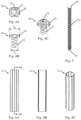
- the outer transverse dimensions of the head T H and coil body Tc in two possible embodiments are illustrated in Figs. 4B and 8B and correspond to the width of the head and the diameter of the coil body. It should be noted that in which the head and/or the coil body are noncircular, the head and/or coil body may have both minimum and maximum transverse dimensions.
- a transverse dimension of the distally extending coil body may be varied to offer different clinical benefits associated with the surgical fastener.
- the distally extending coil body has an inner transverse dimension that is approximately the same as a pitch diameter of the threading within the through hole of the fastener head.
- the distally extending coil body engages the corresponding external threading on the mandrel.
- the coil body may extend through the through hole of the fastener head to form the internal threading of the fastener head.
- the coil body is engaged with, and is thus supported by, the mandrel along its entire length which may help to guide and stabilize the coil body of the surgical fastener during deployment.
- supporting the coil body during deployment may aid in preventing unwanted buckling or compression of the surgical fastener during deployment.
- a surgical fastener including a coil body with a smaller ratio of coil transverse dimension to fastener head transverse dimension may provide increased mechanical advantage during deployment when a rotator applies a torque to the head of such a surgical fastener.
- a minimum inner transverse dimension of the distally extending coil body is larger than a maximum transverse dimension of the through hole and a maximum outer transverse dimension of the threaded portion of the mandrel.
- the surgical fasteners are supported on the threaded portion of the mandrel solely by the internal threading located in the through holes of the individual fastener heads. Since the distally extending coil body of the surgical fastener is not supported on the corresponding mandrel, the individual coil bodies may be subject to compression and/or buckling during deployment. Therefore, in some embodiments, it may be desirable to provide one or more guide features associated with the surgical fasteners to avoid buckling and/or compression of the distally extending coil bodiess and ensure proper insertion into tissue during deployment.
- the coil bodies and heads of the surgical fasteners may be made from any appropriate materials or combination of materials including various appropriate metals and polymers. Additionally, the material may be selected such that the surgical fastener is non-absorbable or bioabsorable as the current disclosure is not so limited.
- the distally extending coil body and the head may be made from: stainless steels such as 316L stainless steel; nickel titanium based alloys such as nitinol; polypropylene; high density polyurethane; ultrahigh molecular weight polyethylene (UHMWPE); nylon; polyester; magnesium; zinc; polylactic acid; polyglycolic acid; or any other appropriate material.
- the various components of the deployment device may be made from any appropriate material or combination of materials including various appropriate metals and polymers.
- Appropriate materials include, but are not limited to: stainless steels such as 316L stainless steel; nickel titanium based alloys such as nitinol; polypropylene; high density polyurethane; ultrahigh molecular weight polyethylene (UHMWPE); nylon; polyester; or any other appropriate material.
- the currently disclosed embodiments are directed to a laparoscopic device.
- the current disclosure is not limited to laparoscopic devices.
- the currently disclosed surgical fasteners and associated deployment devices may be used with any appropriate device capable of deploying a fastener into tissue.
- any of the currently disclosed components, or combination of disclosed components could be incorporated into an endoscopic device, a borescopic device, a catheter, a surgical instrument for use in "open" procedures, or any other appropriate surgical instrument.
- the deployment device may be loaded with one or more fasteners prior to being provided to an end user, or it may be constructed to allow the user to load one or more fasteners.
- Fig. 1 depicts a deployment device in the form of a laparoscopic surgical instrument 2 for deploying one or more surgical fasteners.
- the deployment device 2 includes a handle 4 at a proximal end of the device.
- the handle includes a trigger 6.
- the deployment device also includes an outer elongated shaft 16 extending in a distal direction from the handle 4.
- a surgical fastener is deployed from a distal tip of the elongated shaft 16.
- the deployed surgical fastener may be deployed into any appropriate prosthetic, bone, and/or tissue.
- a surgical fastener can be deployed into a soft tissue repair fabric, such as a surgical mesh, as well as an underlying tissue for repairing a hernia.
- Fig. 2 depicts an exploded view of the deployment device 2 of Fig. 1 .
- the deployment device includes a mandrel 10, a rotator 14, and an outer elongated shaft 16.
- the mandrel 10 includes a threaded portion 12 for supporting one or more surgical fasteners, not depicted.
- the mandrel 10 is disposed within the rotator 14 which is disposed in the outer elongated shaft 16.
- the trigger 6 is coupled to the rotator 14 via a transmission 8 such that actuation of the trigger 6 rotates the rotator 14 relative to the mandrel 10.
- this rotation of the rotator 14 relative to the mandrel 10 rotates the surgical fasteners disposed on the threaded portion 12 of the mandrel, not depicted. Rotation of the surgical fasteners relative to the threaded portion 12 of the mandrel displaces the surgical fasteners in a distal direction and deploys a distal most fastener into a prosthetic and/or tissue.
- the rotator 14 and transmission 8 may be embodied in any number of different ways in order to rotate the fasteners relative to the mandrel 10. Therefore, it should be understood, that the current disclosure is not limited to only the rotator 14 and transmission 8 depicted in the figures and described below.
- the elongated shaft 16 is articulable.
- the mandrel 10 and the rotator 14 be designed to accommodate articulation of the elongated shaft 16 while still being capable of deploying a surgical fastener.
- This may be provided in any number of ways.
- rotatable links and/or slots may be provided along a portion of the mandrel and/or rotator length in the articulable portion of the device.
- the mandrel and/or rotator may be made from a flexible material, or include a flexible material within the articulated portion to permit rotation of the rotator when articulated.
- the rotator and mandrel may be made from rigid materials located in a rigid distal portion of the elongated shaft that articulates about a joint.
- a transmission may then be used to transmit power from the trigger and through the articulating joint to deploy a surgical fastener.
- Other embodiments to permit articulation of the deployment device are also possible. Further embodiments in which the deployment device is not articulable are also possible.
- the mandrel 10 is held rotationally and axially stationary relative to the handle 4 and/or the outer elongated shaft 16.
- the mandrel 10 might also be held rotationally stationary relative to the handle 4 and/or outer elongated shaft 16 and may be movable in a proximal and distal direction.
- the mandrel 10 may advance in a distal direction during deployment of a surgical fastener to extend the mandrel outside of the distal end of the outer elongated shaft 16.
- the mandrel 10 may then retract in a proximal direction after a surgical fastener has been deployed.
- the mandrel may include either a pointed distal tip 26 to aid in positioning the fastener relative to soft and/or hard tissues, or the distal tip 26 may be blunt as the current disclosure is not limited in this fashion.
- the threaded portion 12 of the mandrel and corresponding threading on the surgical fasteners may include multiple threads.
- the threaded portion 12 of the mandrel and the internal threading of the surgical fasteners, not depicted may include at least two threads, three threads, four threads, or any other desirable number of threads as the current disclosure is not limited in this respect.
- the multiple threads may also help to stabilize the surgical fasteners on the mandrel as they are distally displaced through the elongated shaft and subsequently deployed into an underlying prosthetic and/or tissue.
- FIG. 3 depicts a close-up exploded perspective view of the distal end of one embodiment of the mandrel 10 and the rotator 14.
- a plurality of surgical fasteners 18 are disposed on the threaded portion 12 of the mandrel.
- the surgical fasteners 18 include a head 20 and a distally extending coil body 22 attached to the head.
- the head 20 and distally extending coil body 22 of each surgical fastener 18 are constructed and arranged to engage with the threaded portion 12 of the mandrel.
- the mandrel 10, as well as the plurality of surgical fasteners 18 disposed thereon are positioned within the rotator 14.
- the depicted rotator 14 is an outer drive cannula with a cross-sectional profile that complements a shape and size of the fastener heads 20. Therefore, rotation of the rotator 14 relative to the mandrel rotates the fasteners 18 relative to the threaded portion 12 of the stationary mandrel. This rotation of the surgical fasteners 18 relative to the threaded portion 12 of the mandrel, distally displaces the one or more surgical fasteners and deploys a distal most surgical fastener into an underlying prosthetic and/or tissue.
- Figs. 4A-4C depict one embodiment of a surgical fastener 18 for use with the deployment device described above.
- the surgical fastener 18 includes a distally extending coil body 22 that is attached to a head 20 including a through hole 24 with an internal thread.
- the inner transverse dimension of the distally extending coil body 22 is selected such that one or more of the individual coil windings of the distally extending coil body 22 engages with the threaded portion of the mandrel along either a portion or substantially the entire length of the coil body 22 distally extending from the head 20.
- the coil body 22 may pass through the through hole 24 to form the internal threading located therein.
- the coil body 22 is attached to the head 20 using any appropriate method.
- the coil body 22 may be integrally formed with the head 20 or it may be manufactured separately and attached using a compression fit, adhesives, mechanical interlocking features, threading, interference fits, or any other appropriate method.
- Fig. 5 depicts an embodiment of a mandrel 10 including a threaded portion 12a for use with the surgical fastener depicted in Figs. 4A-4C .
- the threaded portion 12a includes a single thread with a different pitch to the coil windings of the coil body 22. Additionally, the threaded portion 12a is sized to engage the internal threading of the through hole 24. While a blunted distal tip 26 is depicted, a pointed tip might also be used.
- the head 20 of the surgical fastener has a shape including a series of flats and rounded portions.
- the rotator 14, corresponding to the distally extended elongated outer drive cannula depicted in Figs. 6A-6C includes an internal cross-sectional shape that complements the shape and size of the heads 20 of the surgical fasteners.
- the specific shape of the heads 20 and the internal cross-section of the rotator 14 is selected such that rotation of the rotator 14 rotates the fasteners 18 relative to the mandrel 10 with minimal or no slip. While a specific shape is depicted in the figures, other shapes are also possible.
- the fastener heads and corresponding cross-sectional shape of the rotator may also correspond to a triangle, a quadrilateral, a pentagon, an asymmetrical shape, or any other appropriate shape capable of transferring rotation of the rotator 14 to the fasteners 18. It should be understood that embodiments in which the rotator only complements a portion of the shape and size of the heads also are contemplated.
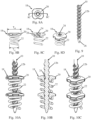
- Figs. 7A-7C depict various cross-sectional views of the assembled mandrel 10, rotator 14, and a plurality of surgical fasteners 18 to help illustrate how the deployment device functions.
- the mandrel is disposed inside of the rotator 14 with the plurality of surgical fasteners 18 disposed thereon.
- the heads 20 of the surgical fasteners are engaged with the internal cross-section of the rotator 14 and the coil windings of the coil body 22 are engaged with the thread portion 12a of the mandrel along their entire lengths.
- the rotator 14 is rotated relative to the mandrel 10.
- the internal cross-section of the rotator applies a torque to the head 20 of each fastener 18.
- This torque rotates the fasteners 18 relative to the mandrel 10. Due to the internal threading of the coil bodies and/or heads engaging the threaded portion 12a of the mandrel, rotating the heads will apply a distally directed force to the internal threading of the surgical fasteners 18 and displace the surgical fasteners 18 in a distal direction.
- a distal most fastener is displaced out of the distal end of the deployment device and into an underlying prosthetic and/or tissue.
- the pitch of the coil windings of the coil body is different from a pitch of the internal threading of the through hole and the associated threaded portion of the mandrel it is engaged with.
- the coil windings might have a pitch in a relaxed position that is less than a pitch of the internal threading of the through hole and the associated threaded portion of the mandrel.
- the coil body may be deformed to an elongated state while it is positioned on the threaded portion of the mandrel.
- the coil body After the coil body is deployed into tissue, the coil body may contract towards its relaxed position and provide a compressive force to the prosthetic and/or tissue it is deployed into. Similar to the above, in order to provide a tensile force to the prosthetic and/or tissue, the coil windings may have a pitch that is greater than a pitch of the threaded corresponding portion of the mandrel.
- Figs. 8A-8D and 9 depict another embodiment of a surgical fastener and an associated deployment device.
- the surgical fastener 18 includes a distally extending coil body 22 attached to a head 20 including a threaded through hole 24.
- an inner transverse dimension of the coil body 22 is greater than a transverse dimension of the through hole 24 and an associated threaded portion 12b of the mandrel depicted in Fig. 9 .
- the coil body 22 may be attached to the head 20 in any appropriate fashion, in the depicted embodiment, a proximal end of the coil body 22 creates an compression fit with a shoulder 28 of the head.
- the surgical fastener 18 will be solely supported on the threaded portion of the mandrel by the internal threading located in the through hole 24.
- the internal threading of the through hole 24 may include multiple threads to increase the stability of the surgical fastener on the mandrel as well as the force applied during deployment.
- the surgical fastener 18 includes two internal threads within through hole 24.
- a fastener head including a single thread might include at least a full turn of the thread.
- a fastener head including two threads might include at least a half turn of each thread to provide at least a combined full turn of engagement with the multiple threads. It should be understood that other numbers of threads and either greater or lesser amounts of combined thread engagement are also possible.
- Fig. 9 presents an embodiment of a mandrel 10 including a threaded portion 12b configured to engage with the internal threading of the through hole 24 of the surgical fastener depicted in Figs. 8A-8D . Since the surgical fastener depicted in the figures has two internal threads, the threaded portion 12b of the mandrel also has two corresponding external threads as well. Additionally, the mandrel 10 also includes a pointed distal tip 26. As noted above, the pointed distal tip can be inserted into a prosthetic and/or tissue to aid in positioning the fastener.
- the mandrel 10 may either be displaced to extend out of a distal end of an associated deployment device, or it may fixed such that it extends out of the distal end of an associated deployment device. While a pointed distal tip has been depicted with the current embodiment, a blunt tip might also be used.
- Figs. 10A-10C depict the surgical fasteners 18 of Figs. 8A-8D including a coil body that has a larger minimum inner transverse dimension than a maximum outer transverse dimension of the associated through hole and/or threaded portion of the mandrel. To aid in visualization, an associated rotator is not depicted. Similar to the other embodiment described above, the internal threading of the through hole 24 of each surgical fastener 18 is engaged with the threaded portion 12b of the mandrel. However, as noted above, the distally extending coils 22 are not engaged with the threaded portion 12b of the mandrel because it has a larger inner transverse dimension.
- the threaded portion 12b of the mandrel will apply a distally directed force to the internal threading located in the through hole 24 of each surgical fastener, but will not interact with the distally extending coil bodies directly. Therefore, similar to the other embodiment, this results in the surgical fasteners undergoing both rotation and displacement in a distal direction to deploy the surgical fasteners from the distal end of a deployment device and into a desired prosthetic and/or tissue.
- rotator capable of rotating the surgical fasteners relative to the mandrel may be used.
- Appropriate rotators may also include: different cross-sectional shapes; distally extending arms that engage corresponding features on the surgical fasteners; a rotator that only engages a portion of the cross-section of the surgical fasteners; keyed features, combinations of the above, and any other appropriate rotator.
- any appropriate fastener head capable of being engaged by the rotator may be used.
- other types of features and/or shapes, such as slots, holes, grooves, tabs, and/or combinations of the above, might be used to associate the surgical fasteners with the rotator.
- the surgical fasteners may include at least two, three, or any desirable number of parallel and distally extending coil windings attached to the fastener head.
Landscapes
- Health & Medical Sciences (AREA)
- Life Sciences & Earth Sciences (AREA)
- Surgery (AREA)
- Molecular Biology (AREA)
- General Health & Medical Sciences (AREA)
- Biomedical Technology (AREA)
- Heart & Thoracic Surgery (AREA)
- Medical Informatics (AREA)
- Nuclear Medicine, Radiotherapy & Molecular Imaging (AREA)
- Animal Behavior & Ethology (AREA)
- Engineering & Computer Science (AREA)
- Public Health (AREA)
- Veterinary Medicine (AREA)
- Surgical Instruments (AREA)
- Orthopedic Medicine & Surgery (AREA)
- Neurology (AREA)
- Prostheses (AREA)
Claims (12)
- Chirurgische Befestigungselement-Einsatzvorrichtung (2), umfassend:einen Griff (4);eine Welle (16), die sich distal von dem Handgriff erstreckt;ein chirurgisches Befestigungselement (18), das in der Welle angeordnet ist, wobei das chirurgische Befestigungselement einen Kopf (20) und einen sich distal erstreckenden Spulenkörper (22) beinhaltet, der an dem Kopf (20) befestigt ist,dadurch gekennzeichnet, dass der Kopf (20) ein Durchgangsloch (24) mit einem Innengewinde aufweist; und die chirurgische Befestigungselement-Einsatzvorrichtung ferner einen Dorn (10) umfasst, der einen Gewindeabschnitt (12) beinhaltet,wobei der Gewindeabschnitt (12) mit dem Innengewinde des Kopfes (20) und dem sich distal erstreckenden Spulenkörper (22) des chirurgischen Befestigungselements (18) in Eingriff steht,wobei eine Steigung des Innengewindes des Durchgangslochs (24) und des Gewindeabschnitts des Dorns (10), der mit dem Innengewinde in Eingriff steht, von einer Steigung des Spulenkörpers (22) des chirurgischen Befestigungselements (18) verschieden ist, undeinen dem chirurgischen Befestigungselement (18) zugehörigen Rotator (14), wobei der Rotator (14) das chirurgische Befestigungselement (18) relativ zu dem Dorn (10) dreht, um das chirurgische Befestigungselement (18) in eine distale Richtung zu verschieben.
- Chirurgische Befestigungselement-Einsatzvorrichtung nach Anspruch 1, wobei die Steigung des Spulenkörpers (22) des chirurgischen Befestigungselements (18) größer als die Steigung des Gewindeabschnitts (12) des Dorns (10) ist.
- Chirurgische Befestigungselement-Einsatzvorrichtung nach Anspruch 1, wobei die Steigung des Spulenkörpers (22) des chirurgischen Befestigungsmittels (18) geringer als die Steigung des Innengewindes (24) des Durchgangslochs (24) und des Gewindeabschnitts (12) des Dorns (10) ist.
- Chirurgische Befestigungselement-Einsatzvorrichtung nach einem der Ansprüche 1-3, wobei der Gewindeabschnitt (12) des Dorns (10) und das entsprechende Innengewinde des chirurgischen Befestigungselements (18) mindestens zwei Gewinde beinhaltet.
- Chirurgische Befestigungselement-Einsatzvorrichtung nach einem der Ansprüche 1-4, wobei der Dorn (10) stationär ist.
- Chirurgische Befestigungselement-Einsatzvorrichtung nach einem der Ansprüche 1-5, wobei der Dorn (10) drehstationär ist.
- Chirurgische Befestigungselement-Einsatzvorrichtung nach einem der Ansprüche 1-4, wobei sich der Dorn (10) in einer proximalen und einer distalen Richtung hin- und herbewegt.
- Chirurgische Befestigungselement-Einsatzvorrichtung nach einem der Ansprüche 1-7, wobei der Spulenkörper (22) des chirurgischen Befestigungselements (18) mindestens zwei separate Spulenwicklungen beinhaltet, die parallel zueinander sind und sich distal von dem Kopf (20) erstrecken.
- Chirurgische Befestigungselement-Einsatzvorrichtung nach einem der Ansprüche 1-8, wobei eine gesamte Länge des Spulenkörpers, die sich distal des Kopfes befindet, so konstruiert und angeordnet ist, dass sie mit dem Gewindedorn in Eingriff steht.
- Chirurgische Befestigungselement-Einsatzvorrichtung nach einem der Ansprüche 1-9, wobei der Spulenkörper (22) des chirurgischen Befestigungselements (18) durch eine Verbindung zwischen dem Kopf (20) und dem Spulenkörper (22), umfassend mindestens eines von einer Kompressionspassung, einem Klebstoff, mechanischen Verriegelungsmerkmalen und einer Presspassung, drehfest mit dem Kopf (20) verbunden ist.
- Chirurgische Befestigungselement-Einsatzvorrichtung nach einem der Ansprüche 1-10, wobei der Dorn (10) eine spitze distale Spitze beinhaltet.
- Chirurgische Befestigungselement-Einsatzvorrichtung nach einem der Ansprüche 1-11, wobei eine minimale innere Querabmessung des Spulenkörpers (22) des chirurgischen Befestigungselements (18) größer als eine maximale Querabmessung des Gewindeabschnitts des Dorns (10) ist.
Applications Claiming Priority (3)
| Application Number | Priority Date | Filing Date | Title |
|---|---|---|---|
| US14/075,398 US9675353B2 (en) | 2013-11-08 | 2013-11-08 | Surgical fasteners and associated deployment devices |
| EP17186695.7A EP3266385B1 (de) | 2013-11-08 | 2014-11-06 | Chirurgische befestigungselemente |
| EP14192140.3A EP2870928B1 (de) | 2013-11-08 | 2014-11-06 | Chirurgische Befestigungselemente und zugehörige Einsatzvorrichtungen |
Related Parent Applications (2)
| Application Number | Title | Priority Date | Filing Date |
|---|---|---|---|
| EP14192140.3A Division EP2870928B1 (de) | 2013-11-08 | 2014-11-06 | Chirurgische Befestigungselemente und zugehörige Einsatzvorrichtungen |
| EP17186695.7A Division EP3266385B1 (de) | 2013-11-08 | 2014-11-06 | Chirurgische befestigungselemente |
Publications (3)
| Publication Number | Publication Date |
|---|---|
| EP3797708A1 EP3797708A1 (de) | 2021-03-31 |
| EP3797708B1 true EP3797708B1 (de) | 2025-01-01 |
| EP3797708C0 EP3797708C0 (de) | 2025-01-01 |
Family
ID=51862210
Family Applications (3)
| Application Number | Title | Priority Date | Filing Date |
|---|---|---|---|
| EP14192140.3A Active EP2870928B1 (de) | 2013-11-08 | 2014-11-06 | Chirurgische Befestigungselemente und zugehörige Einsatzvorrichtungen |
| EP20186342.0A Active EP3797708B1 (de) | 2013-11-08 | 2014-11-06 | Chirurgische befestigungselemente und zugehörige einsatzvorrichtungen |
| EP17186695.7A Active EP3266385B1 (de) | 2013-11-08 | 2014-11-06 | Chirurgische befestigungselemente |
Family Applications Before (1)
| Application Number | Title | Priority Date | Filing Date |
|---|---|---|---|
| EP14192140.3A Active EP2870928B1 (de) | 2013-11-08 | 2014-11-06 | Chirurgische Befestigungselemente und zugehörige Einsatzvorrichtungen |
Family Applications After (1)
| Application Number | Title | Priority Date | Filing Date |
|---|---|---|---|
| EP17186695.7A Active EP3266385B1 (de) | 2013-11-08 | 2014-11-06 | Chirurgische befestigungselemente |
Country Status (4)
| Country | Link |
|---|---|
| US (4) | US9675353B2 (de) |
| EP (3) | EP2870928B1 (de) |
| CA (1) | CA2870300C (de) |
| ES (2) | ES2660220T3 (de) |
Families Citing this family (13)
| Publication number | Priority date | Publication date | Assignee | Title |
|---|---|---|---|---|
| US10368870B2 (en) | 2013-11-08 | 2019-08-06 | C.R. Bard, Inc. | Surgical fastener |
| US9675353B2 (en) | 2013-11-08 | 2017-06-13 | C.R. Bard, Inc. | Surgical fasteners and associated deployment devices |
| US9615830B2 (en) | 2013-11-08 | 2017-04-11 | C.R. Bard, Inc. | Surgical fastener |
| US9445814B2 (en) | 2013-11-08 | 2016-09-20 | C.R. Bard, Inc. | Surgical fastener |
| US11701096B2 (en) | 2015-05-28 | 2023-07-18 | National University Of Ireland, Galway | Fistula treatment device |
| US10028733B2 (en) | 2015-05-28 | 2018-07-24 | National University Of Ireland, Galway | Fistula treatment device |
| US10405858B2 (en) | 2015-06-30 | 2019-09-10 | C.R. Bard, Inc. | Actuation lockout for a surgical instrument |
| US10702264B2 (en) * | 2016-01-25 | 2020-07-07 | TransEasy Medical Tech.Co., Ltd | Fixing device for soft tissue |
| EP3541298B1 (de) | 2017-06-09 | 2021-08-18 | Signum Surgical Limited | Implantat zum verschliessen einer öffnung in einem gewebe |
| EP3651671B1 (de) * | 2017-07-10 | 2023-08-16 | Trace Orthopedics, LLC | Ankersystem mit doppelfunktion |
| US10675030B2 (en) | 2017-08-04 | 2020-06-09 | C.R. Bard, Inc. | Absorbable surgical coil fastener |
| AU2021284392A1 (en) * | 2020-06-04 | 2023-01-19 | Trace Orthopedics, Llc | Dual-function anchor system |
| WO2022096753A1 (en) | 2020-11-09 | 2022-05-12 | Medos International Sarl | Multiple set screw insertion instrument and methods |
Family Cites Families (53)
| Publication number | Priority date | Publication date | Assignee | Title |
|---|---|---|---|---|
| US2407879A (en) | 1944-07-08 | 1946-09-17 | Aircraft Screw Prod Co | Composite nut |
| US3229374A (en) | 1963-08-20 | 1966-01-18 | Comorau Leo | Thread gauges |
| US4318651A (en) * | 1980-04-08 | 1982-03-09 | Ragen Peter D | Fastener for blind holes |
| US4762453A (en) | 1986-01-29 | 1988-08-09 | Textron, Inc. | Helical coil fastener |
| FR2607560A1 (fr) * | 1986-12-01 | 1988-06-03 | Plombelec | Element d'ancrage d'un support dans un materiau presentant une faible resistance a l'arrachement |
| GB2217420A (en) | 1988-04-09 | 1989-10-25 | Cryotherm Limited | Screws for joining semi-rigid mats |
| US5256133A (en) * | 1990-09-05 | 1993-10-26 | Spitz Robert M | Device for correcting stress urinary incontinence |
| AU1011595A (en) | 1994-01-13 | 1995-07-20 | Ethicon Inc. | Spiral surgical tack |
| US5662683A (en) | 1995-08-22 | 1997-09-02 | Ortho Helix Limited | Open helical organic tissue anchor and method of facilitating healing |
| US7611521B2 (en) | 1996-09-13 | 2009-11-03 | Tendon Technology, Ltd. | Apparatus and methods for tendon or ligament repair |
| US5733307A (en) | 1996-09-17 | 1998-03-31 | Amei Technologies, Inc. | Bone anchor having a suture trough |
| US5830221A (en) * | 1996-09-20 | 1998-11-03 | United States Surgical Corporation | Coil fastener applier |
| WO1998011814A2 (en) * | 1996-09-20 | 1998-03-26 | United States Surgical Corporation | Coil fastener applier and remover |
| US6248108B1 (en) | 1998-09-30 | 2001-06-19 | Bionx Implants Oy | Bioabsorbable surgical screw and washer system |
| CA2351531C (en) * | 1998-11-18 | 2007-04-24 | General Surgical Innovations, Inc. | Helical fastener and applicator for surgical procedures |
| FR2812188B1 (fr) | 2000-07-31 | 2003-06-13 | Spinevision Sa | Cage d'immobilisation du rachis et d'osteosynthese, procede de fabrication de ladite cage et equipement de forage pour l'implantation de ladite cage |
| US6953462B2 (en) | 2000-10-05 | 2005-10-11 | The Cleveland Clinic Foundation | Apparatus for implantation into bone |
| US6551319B2 (en) | 2000-11-08 | 2003-04-22 | The Cleveland Clinic Foundation | Apparatus for implantation into bone |
| US6488683B2 (en) * | 2000-11-08 | 2002-12-03 | Cleveland Clinic Foundation | Method and apparatus for correcting spinal deformity |
| US6409445B1 (en) | 2001-01-24 | 2002-06-25 | James R. Beale | Push pin with rotatable anchor section |
| US8231639B2 (en) | 2001-11-28 | 2012-07-31 | Aptus Endosystems, Inc. | Systems and methods for attaching a prosthesis within a body lumen or hollow organ |
| GB2417208B (en) | 2001-11-28 | 2006-06-28 | Aptus Endosystems Inc | Intraluminal prosthesis attachment systems |
| DE60311806T2 (de) | 2002-06-11 | 2007-10-31 | Tyco Healthcare Group Lp, Norwalk | Klammer zur Befestigung von Hernia-Netz |
| EP2298184A1 (de) | 2003-06-13 | 2011-03-23 | Tyco Healthcare Group LP | Verbindung aus mehreren Elementen für ein Operationsinstrument und resorbierbarer Schraubenbefestiger |
| CA2532882A1 (en) | 2003-07-11 | 2005-01-20 | Endogun Medical Systems Ltd. | Surgical fasteners and devices for surgical fastening |
| US20050187568A1 (en) * | 2004-02-20 | 2005-08-25 | Klenk Alan R. | Devices and methods for closing a patent foramen ovale with a coil-shaped closure device |
| JP4280773B2 (ja) | 2004-03-30 | 2009-06-17 | 中央発条工業株式会社 | 緩み止めナット |
| US10478179B2 (en) | 2004-04-27 | 2019-11-19 | Covidien Lp | Absorbable fastener for hernia mesh fixation |
| US8114099B2 (en) | 2004-04-27 | 2012-02-14 | Tyco Healthcare Group Lp | Absorbable anchor for hernia mesh fixation |
| US20090118776A1 (en) | 2004-09-24 | 2009-05-07 | Biomec, Inc. | Tissue anchors |
| US7862573B2 (en) * | 2006-04-21 | 2011-01-04 | Darois Roger E | Method and apparatus for surgical fastening |
| US20080004626A1 (en) * | 2006-05-26 | 2008-01-03 | Glazer Paul A | Orthopedic coil screw insert |
| US7955362B2 (en) * | 2006-07-21 | 2011-06-07 | Merlot Orthopedix Inc. | Apparatus and method for body tissue fixation |
| US8087142B2 (en) | 2008-07-02 | 2012-01-03 | Easylap Ltd. | Pivoting tacker |
| US20100010520A1 (en) * | 2008-07-11 | 2010-01-14 | Olympus Medical Systems Corp. | Tissue fastener |
| KR20110073452A (ko) | 2008-08-15 | 2011-06-29 | 키네틱 스파인 테크놀로지스 인크. | 뼈 고정나사 |
| US20100145393A1 (en) | 2008-12-05 | 2010-06-10 | Medicinelodge, Inc. | Medical and dental porous implants |
| CN102368969B (zh) | 2009-04-02 | 2014-03-12 | 斯恩蒂斯有限公司 | 锁定螺旋锚固装置 |
| US20100274266A1 (en) | 2009-04-22 | 2010-10-28 | Ofir Rimer | Rotary tack |
| US8523881B2 (en) | 2010-07-26 | 2013-09-03 | Valtech Cardio, Ltd. | Multiple anchor delivery tool |
| JP5805668B2 (ja) | 2010-01-26 | 2015-11-04 | アータック メディカル (2013) リミテッド | 関節運動式医療機器 |
| US20110295282A1 (en) * | 2010-05-26 | 2011-12-01 | Tyco Healthcare Group Lp | Fastener and drive method for soft tissue repair |
| US8814904B2 (en) | 2010-10-26 | 2014-08-26 | Ziptek LLC. | Surgical suture system |
| JP6130302B2 (ja) | 2011-01-28 | 2017-05-17 | アピカ カーディオヴァスキュラー リミテッド | 組織壁の刺し傷を封止するシステム |
| US9072511B2 (en) | 2011-03-25 | 2015-07-07 | Kardium Inc. | Medical kit for constricting tissue or a bodily orifice, for example, a mitral valve |
| EP3725269A1 (de) | 2011-06-23 | 2020-10-21 | Valtech Cardio, Ltd. | Verschlusselement zur verwendung mit einer annuloplastiestruktur |
| FR2977471B1 (fr) | 2011-07-07 | 2013-07-05 | Aspide Medical | Dispositif comprenant une pluralite d'implants pour la fixation de materiel prothetique |
| CA2849887A1 (en) | 2011-09-26 | 2013-04-04 | Artack Medical (2013) Ltd. | Surgical fastening device and method |
| US9500217B2 (en) | 2012-07-03 | 2016-11-22 | Jörg Schwarzbich | Method for producing threaded parts |
| US9675353B2 (en) | 2013-11-08 | 2017-06-13 | C.R. Bard, Inc. | Surgical fasteners and associated deployment devices |
| US9445814B2 (en) | 2013-11-08 | 2016-09-20 | C.R. Bard, Inc. | Surgical fastener |
| US9615830B2 (en) | 2013-11-08 | 2017-04-11 | C.R. Bard, Inc. | Surgical fastener |
| US10368870B2 (en) | 2013-11-08 | 2019-08-06 | C.R. Bard, Inc. | Surgical fastener |
-
2013
- 2013-11-08 US US14/075,398 patent/US9675353B2/en active Active
-
2014
- 2014-11-06 EP EP14192140.3A patent/EP2870928B1/de active Active
- 2014-11-06 EP EP20186342.0A patent/EP3797708B1/de active Active
- 2014-11-06 ES ES14192140.3T patent/ES2660220T3/es active Active
- 2014-11-06 ES ES17186695T patent/ES2828671T3/es active Active
- 2014-11-06 EP EP17186695.7A patent/EP3266385B1/de active Active
- 2014-11-07 CA CA2870300A patent/CA2870300C/en active Active
-
2017
- 2017-05-05 US US15/587,689 patent/US10646225B2/en active Active
-
2020
- 2020-04-16 US US16/850,065 patent/US11344306B2/en active Active
-
2021
- 2021-10-13 US US17/500,236 patent/US12089848B2/en active Active
Also Published As
| Publication number | Publication date |
|---|---|
| ES2660220T3 (es) | 2018-03-21 |
| EP2870928A1 (de) | 2015-05-13 |
| CA2870300A1 (en) | 2015-05-08 |
| ES2828671T3 (es) | 2021-05-27 |
| US20200237374A1 (en) | 2020-07-30 |
| US20150133964A1 (en) | 2015-05-14 |
| EP3797708C0 (de) | 2025-01-01 |
| US20220031363A1 (en) | 2022-02-03 |
| US9675353B2 (en) | 2017-06-13 |
| EP2870928B1 (de) | 2017-12-20 |
| EP3266385A1 (de) | 2018-01-10 |
| EP3266385B1 (de) | 2020-08-05 |
| US20170231632A1 (en) | 2017-08-17 |
| US11344306B2 (en) | 2022-05-31 |
| EP3797708A1 (de) | 2021-03-31 |
| CA2870300C (en) | 2019-09-24 |
| US10646225B2 (en) | 2020-05-12 |
| US12089848B2 (en) | 2024-09-17 |
Similar Documents
| Publication | Publication Date | Title |
|---|---|---|
| US12089848B2 (en) | Surgical fasteners and associated deployment devices | |
| US11627965B2 (en) | Surgical fastener | |
| EP2829237B1 (de) | Erweiterbare, absorbierbare Klammer | |
| EP2760345B1 (de) | Chirurgische befestigungsvorrichtung | |
| EP2701612B1 (de) | Vorschiebende nahtdurchgangsvorrichtung | |
| US20110178537A1 (en) | Tissue repair implant and delivery device and method | |
| JP6698189B6 (ja) | 手術器具内部におけるファスナのハンドリング | |
| EP2361559A1 (de) | Gerät für chirurgische Befestigung | |
| EP2870929B1 (de) | Vorrichtung zur chirurgischen Befestigung | |
| EP2967557B1 (de) | Chirurgischen instrument zur handhabung von befestigungselementen | |
| DE202009018081U1 (de) | Chirurgische Klammer und Applikator | |
| HK1200304B (en) | Surgical fastening device |
Legal Events
| Date | Code | Title | Description |
|---|---|---|---|
| PUAI | Public reference made under article 153(3) epc to a published international application that has entered the european phase |
Free format text: ORIGINAL CODE: 0009012 |
|
| STAA | Information on the status of an ep patent application or granted ep patent |
Free format text: STATUS: THE APPLICATION HAS BEEN PUBLISHED |
|
| AC | Divisional application: reference to earlier application |
Ref document number: 2870928 Country of ref document: EP Kind code of ref document: P Ref document number: 3266385 Country of ref document: EP Kind code of ref document: P |
|
| AK | Designated contracting states |
Kind code of ref document: A1 Designated state(s): AL AT BE BG CH CY CZ DE DK EE ES FI FR GB GR HR HU IE IS IT LI LT LU LV MC MK MT NL NO PL PT RO RS SE SI SK SM TR |
|
| STAA | Information on the status of an ep patent application or granted ep patent |
Free format text: STATUS: REQUEST FOR EXAMINATION WAS MADE |
|
| 17P | Request for examination filed |
Effective date: 20210817 |
|
| RBV | Designated contracting states (corrected) |
Designated state(s): AL AT BE BG CH CY CZ DE DK EE ES FI FR GB GR HR HU IE IS IT LI LT LU LV MC MK MT NL NO PL PT RO RS SE SI SK SM TR |
|
| GRAP | Despatch of communication of intention to grant a patent |
Free format text: ORIGINAL CODE: EPIDOSNIGR1 |
|
| STAA | Information on the status of an ep patent application or granted ep patent |
Free format text: STATUS: GRANT OF PATENT IS INTENDED |
|
| INTG | Intention to grant announced |
Effective date: 20240506 |
|
| RIN1 | Information on inventor provided before grant (corrected) |
Inventor name: GUPTA, SAURAV V. Inventor name: RANUCCI, KEVIN J. |
|
| GRAS | Grant fee paid |
Free format text: ORIGINAL CODE: EPIDOSNIGR3 |
|
| GRAA | (expected) grant |
Free format text: ORIGINAL CODE: 0009210 |
|
| STAA | Information on the status of an ep patent application or granted ep patent |
Free format text: STATUS: THE PATENT HAS BEEN GRANTED |
|
| AC | Divisional application: reference to earlier application |
Ref document number: 2870928 Country of ref document: EP Kind code of ref document: P Ref document number: 3266385 Country of ref document: EP Kind code of ref document: P |
|
| AK | Designated contracting states |
Kind code of ref document: B1 Designated state(s): AL AT BE BG CH CY CZ DE DK EE ES FI FR GB GR HR HU IE IS IT LI LT LU LV MC MK MT NL NO PL PT RO RS SE SI SK SM TR |
|
| REG | Reference to a national code |
Ref country code: GB Ref legal event code: FG4D |
|
| REG | Reference to a national code |
Ref country code: DE Ref legal event code: R096 Ref document number: 602014091423 Country of ref document: DE |
|
| REG | Reference to a national code |
Ref country code: CH Ref legal event code: EP |
|
| REG | Reference to a national code |
Ref country code: IE Ref legal event code: FG4D |
|
| U01 | Request for unitary effect filed |
Effective date: 20250123 |
|
| U07 | Unitary effect registered |
Designated state(s): AT BE BG DE DK EE FI FR IT LT LU LV MT NL PT RO SE SI Effective date: 20250129 |
|
| PG25 | Lapsed in a contracting state [announced via postgrant information from national office to epo] |
Ref country code: PL Free format text: LAPSE BECAUSE OF FAILURE TO SUBMIT A TRANSLATION OF THE DESCRIPTION OR TO PAY THE FEE WITHIN THE PRESCRIBED TIME-LIMIT Effective date: 20250101 |
|
| PG25 | Lapsed in a contracting state [announced via postgrant information from national office to epo] |
Ref country code: ES Free format text: LAPSE BECAUSE OF FAILURE TO SUBMIT A TRANSLATION OF THE DESCRIPTION OR TO PAY THE FEE WITHIN THE PRESCRIBED TIME-LIMIT Effective date: 20250101 |
|
| PG25 | Lapsed in a contracting state [announced via postgrant information from national office to epo] |
Ref country code: IS Free format text: LAPSE BECAUSE OF FAILURE TO SUBMIT A TRANSLATION OF THE DESCRIPTION OR TO PAY THE FEE WITHIN THE PRESCRIBED TIME-LIMIT Effective date: 20250501 Ref country code: NO Free format text: LAPSE BECAUSE OF FAILURE TO SUBMIT A TRANSLATION OF THE DESCRIPTION OR TO PAY THE FEE WITHIN THE PRESCRIBED TIME-LIMIT Effective date: 20250401 |
|
| PG25 | Lapsed in a contracting state [announced via postgrant information from national office to epo] |
Ref country code: HR Free format text: LAPSE BECAUSE OF FAILURE TO SUBMIT A TRANSLATION OF THE DESCRIPTION OR TO PAY THE FEE WITHIN THE PRESCRIBED TIME-LIMIT Effective date: 20250101 |
|
| PG25 | Lapsed in a contracting state [announced via postgrant information from national office to epo] |
Ref country code: GR Free format text: LAPSE BECAUSE OF FAILURE TO SUBMIT A TRANSLATION OF THE DESCRIPTION OR TO PAY THE FEE WITHIN THE PRESCRIBED TIME-LIMIT Effective date: 20250402 |
|
| PG25 | Lapsed in a contracting state [announced via postgrant information from national office to epo] |
Ref country code: CZ Free format text: LAPSE BECAUSE OF FAILURE TO SUBMIT A TRANSLATION OF THE DESCRIPTION OR TO PAY THE FEE WITHIN THE PRESCRIBED TIME-LIMIT Effective date: 20250101 |
|
| PG25 | Lapsed in a contracting state [announced via postgrant information from national office to epo] |
Ref country code: SM Free format text: LAPSE BECAUSE OF FAILURE TO SUBMIT A TRANSLATION OF THE DESCRIPTION OR TO PAY THE FEE WITHIN THE PRESCRIBED TIME-LIMIT Effective date: 20250101 |
|
| PG25 | Lapsed in a contracting state [announced via postgrant information from national office to epo] |
Ref country code: SK Free format text: LAPSE BECAUSE OF FAILURE TO SUBMIT A TRANSLATION OF THE DESCRIPTION OR TO PAY THE FEE WITHIN THE PRESCRIBED TIME-LIMIT Effective date: 20250101 |
|
| PLBE | No opposition filed within time limit |
Free format text: ORIGINAL CODE: 0009261 |
|
| STAA | Information on the status of an ep patent application or granted ep patent |
Free format text: STATUS: NO OPPOSITION FILED WITHIN TIME LIMIT |
|
| U20 | Renewal fee for the european patent with unitary effect paid |
Year of fee payment: 12 Effective date: 20251022 |
|
| 26N | No opposition filed |
Effective date: 20251002 |
|
| PGFP | Annual fee paid to national office [announced via postgrant information from national office to epo] |
Ref country code: GB Payment date: 20251023 Year of fee payment: 12 |
|
| U1N | Appointed representative for the unitary patent procedure changed after the registration of the unitary effect |
Representative=s name: KILBURN & STRODE LLP; GB |