EP3797463B1 - Verfahren und system zur batterieverwaltung - Google Patents
Verfahren und system zur batterieverwaltung Download PDFInfo
- Publication number
- EP3797463B1 EP3797463B1 EP20707977.3A EP20707977A EP3797463B1 EP 3797463 B1 EP3797463 B1 EP 3797463B1 EP 20707977 A EP20707977 A EP 20707977A EP 3797463 B1 EP3797463 B1 EP 3797463B1
- Authority
- EP
- European Patent Office
- Prior art keywords
- battery
- user
- charging
- implementations
- information
- Prior art date
- Legal status (The legal status is an assumption and is not a legal conclusion. Google has not performed a legal analysis and makes no representation as to the accuracy of the status listed.)
- Active
Links
Images


Classifications
-
- H—ELECTRICITY
- H02—GENERATION; CONVERSION OR DISTRIBUTION OF ELECTRIC POWER
- H02J—ELECTRIC POWER NETWORKS; CIRCUIT ARRANGEMENTS OR SYSTEMS FOR SUPPLYING OR DISTRIBUTING ELECTRIC POWER; SYSTEMS FOR STORING ELECTRIC ENERGY
- H02J7/00—Circuit arrangements for charging or discharging batteries or for supplying loads from batteries
- H02J7/80—Circuit arrangements for charging or discharging batteries or for supplying loads from batteries including monitoring or indicating arrangements
- H02J7/84—Control of state of health [SOH]
-
- H—ELECTRICITY
- H02—GENERATION; CONVERSION OR DISTRIBUTION OF ELECTRIC POWER
- H02J—ELECTRIC POWER NETWORKS; CIRCUIT ARRANGEMENTS OR SYSTEMS FOR SUPPLYING OR DISTRIBUTING ELECTRIC POWER; SYSTEMS FOR STORING ELECTRIC ENERGY
- H02J7/00—Circuit arrangements for charging or discharging batteries or for supplying loads from batteries
- H02J7/80—Circuit arrangements for charging or discharging batteries or for supplying loads from batteries including monitoring or indicating arrangements
- H02J7/82—Control of state of charge [SOC]
-
- H—ELECTRICITY
- H02—GENERATION; CONVERSION OR DISTRIBUTION OF ELECTRIC POWER
- H02J—ELECTRIC POWER NETWORKS; CIRCUIT ARRANGEMENTS OR SYSTEMS FOR SUPPLYING OR DISTRIBUTING ELECTRIC POWER; SYSTEMS FOR STORING ELECTRIC ENERGY
- H02J7/00—Circuit arrangements for charging or discharging batteries or for supplying loads from batteries
- H02J7/90—Regulation of charging or discharging current or voltage
- H02J7/94—Regulation of charging or discharging current or voltage in response to battery current
Definitions
- This relates generally to battery charging, including but not limited to managing battery charging based on battery powered device usage.
- Battery powered devices are becoming increasingly power efficient, allowing for more time to pass before the batteries run out of charge. Users of these devices often keep backup batteries ready for swapping at a moment's notice in order to minimize downtime.
- user demand for fully charged backup batteries may result in keeping the batteries topped off at their highest voltage over extended periods of time, even after charging has completed.
- These backup batteries may be charging for weeks or months, regardless of the actual time required to fully charge the battery (e.g., several hours). Keeping these backup batteries fully charged for extended periods is detrimental to battery performance.
- Battery protection measures which involve passive discharging often result in a backup battery which is not fully charged when the user needs it. Instead, the user either uses the backup battery in its current suboptimal state, or overrides the protection measures and forces the charger to fully charge the backup battery. As a result, either the backup battery does not provide optimal performance (thereby failing earlier than expected), or device downtime is extended while the backup battery is being fully charged (thereby preventing uninterrupted device operation).
- the backup battery may not be 100% charged at the time of the status check. As a result, the user may be confused as to why a backup battery is not fully charged and may replace the battery or the charger as a result.
- US 2017/070081 A1 discloses a battery charging apparatus which includes two or more hybrid battery charging devices.
- Each hybrid battery charging device includes input terminals for connecting a photovoltaic panel, first battery connections for connecting a lead-acid battery, second battery connections for connecting a high-cycle chemical battery, a two-way DC/DC converter, a charge and discharge control system, which is connected to the two-way DC/DC converter, and output terminals for connecting a load.
- US 2015/340897 A1 discloses an electronic apparatus which includes a charger device to obtain information relating to a first battery and to set a limit of a battery charge current of a second battery based on the obtained information.
- US 2016/089992 A1 discloses a 12 volt automotive battery system which includes a first battery coupled to an electrical system, wherein the first battery includes a first battery chemistry. Further, the 12 volt automotive battery system includes a second battery coupled in parallel with the first battery and selectively coupled to the electrical system via a bi-stable relay. The second battery includes a second battery chemistry that has a higher coulombic efficiency than the first battery chemistry. Additionally, the bi-stable relay couples the second battery to the electrical system during regenerative braking to enable the second battery to capture a majority of the power generated during regenerative braking. Furthermore, the bi-stable relay maintains a coupling of the second battery to the electrical system when the vehicle transitions from a key-on position to a key-off position.
- a battery charging system is designed for active interactions between a removable battery docked in a charging base (referred to herein as a “charging battery”) and another removable battery installed in and powering a battery powered device (referred to herein as an "in-use battery”).
- a server system e.g., a cloud server
- learns about battery drain and charging e.g., based on user usage patterns
- the battery charging system controls battery state-of-charge (SOC) and maintains battery state-of-health (SOH) based on a user demand profile and/or device usage characteristics. Such maintenance extends battery longevity and provides extended safety, reliability, and performance of the batteries.
- some implementations include a method performed at a battery charging device that includes one or more processors and memory, the method including receiving battery life information for a first battery (in-use battery) in use in an electronic device, receiving user demand information for the electronic device, and based on the battery life information and/or the user demand information, adjusting a charging rate for a second battery (charging battery) electrically coupled to the battery charging device, the second battery configured for use in the electronic device.
- some implementations include a method performed at a server system that includes one or more processors and memory, the method comprising receiving battery life information for a first battery (in-use battery) in use in an electronic device, receiving user demand information for the electronic device, and based on the battery life information and/or the user demand information, sending charging rate information to a battery charging device for a second battery (charging battery) electrically coupled to the battery charging device, the second battery configured for use in the electronic device.
- a server system that includes one or more processors and memory, the method comprising receiving battery life information for a first battery (in-use battery) in use in an electronic device, receiving user demand information for the electronic device, and based on the battery life information and/or the user demand information, sending charging rate information to a battery charging device for a second battery (charging battery) electrically coupled to the battery charging device, the second battery configured for use in the electronic device.
- the battery life information indicates that the first battery will deplete by a particular time
- adjusting the charging rate includes setting the charging rate so that the second battery will be fully charged by the particular time
- the user demand information is associated with a user of the electronic device and indicates a predicted usage of the electronic device by the user, a user desire to install the second battery in the electronic device at a particular time, and/or information indicating that a user will be away from the electronic device during a particular time period, and adjusting the charging rate includes setting the charging rate so that the second battery will be fully charged in accordance with the predicted usage, the particular time, and/or the particular time period.
- a battery charger is utilized to adjust battery charging rates based on information about the user and one or more of the batteries currently in use. Such a battery charger empowers a user to understand (a) battery health and (b) how to prepare batteries for long term charging and/or storage. Such a battery charger also empowers seamless use of battery powered devices, which is important to many users, particularly in security applications (such as security cameras) where downtime is critical to avoid.
- the battery chargers described herein improve safety, reliability, performance, and cost associated with maintaining batteries.
- the ability to regulate and control battery state-of-charge (SOC) for state-of-health (SOH) reduces the risk posed by batteries at their highest energy state.
- Maintaining batteries within a preferred charge state e.g., less than 70%, 80%, or 90% of full charge
- extended battery longevity saves a user the costs associated with disposing of failed batteries and purchasing new replacement batteries.
- systems and devices are provided with more accurate and effective methods for managing batteries, thereby increasing the accuracy, effectiveness, efficiency, and user satisfaction with such devices.
- Battery powered electronic devices may operate for days, weeks, or months before the battery is fully drained.
- a battery powered camera may operate in a low power mode (e.g., a motion-activated mode) that enables the camera to operate for weeks or months before the battery is drained. It is beneficial for users of such devices to have a replacement battery on hand to swap with a drained battery (or one that is close to being drained) so that device downtime is minimized. However, maintaining the replacement battery at full charge for days, weeks, or months can be damaging to the battery, increasing the likelihood of reduced performance or failure.
- a battery charging device such as a device that communicates with (i) a user device, (ii) the battery powered electronic device, or (iii) the in-use battery, can adjust a charging rate of the replacement battery so that it is fully charged only when a replacement is imminent.
- the battery charging device may use information from a variety of sources to accurately predict when a replacement is needed. For example, the battery charging device may receive current battery life information from the in-use battery and/or from the electronic device.
- the charging device may also receive schedule and use information (referred to herein as user demand information) from the user or from the electronic device that will impact how quickly the in-use battery is drained.
- the charging device may also receive user demand information in the form of user preference information such as how low the user prefers the in-use battery to drain before swapping in the replacement battery.
- a server e.g., a cloud server
- FIGs 1A-1B illustrate representative communication schemes for battery systems in accordance with some implementations.
- the charging device 102 may be in communication with a variety of electronic battery powered devices 104 and a user (via a client device 106) via communications relayed through a server system 108 ( Figure 1A ) and/or via device-to-device connections ( Figure 1B ).
- a battery powered electronic device and the charging device both communicate battery life information (e.g., state-of-charge (SOC) information) to a cloud server.
- SOC state-of-charge
- the cloud server computes and provides status information to the user (e.g., via an application on the user's client device 106).
- the client device 106 may be a mobile phone, tablet computer, laptop computer, desktop computer, or any type of computing device accessible to a user.
- the server system 108 may be a cloud server, local server, or any type of computing system capable of communicating with one or more charging devices 102 and one or more battery powered devices 104.
- a device having a battery includes an integrated state-of-charge chip (e.g., an onboard fuel gauge chip) and communication circuitry.
- the battery communicates information, such as state-of-charge information, battery voltage values, battery temperature values, and/or battery current values.
- the battery is coupled to or otherwise includes measurement and/or maintenance circuitry that provides charge measurement, over-voltage protection, and/or other features.
- a device that includes a battery reads measurement and/or maintenance values from the measurement and/or maintenance circuitry, and communication circuitry which is directly or indirectly coupled to the measurement and/or maintenance circuitry communicates the measurement and/or maintenance values to other devices (e.g., charging device(s) 102, battery powered device(s) 104, client device(s) 106) and/or to a server system 108.
- a battery such as a charging device 102 or a battery powered device 104
- communication circuitry which is directly or indirectly coupled to the measurement and/or maintenance circuitry communicates the measurement and/or maintenance values to other devices (e.g., charging device(s) 102, battery powered device(s) 104, client device(s) 106) and/or to a server system 108.
- FIG. 1A shows a communication scheme 100 in which a charging device 102 is communicatively coupled to various battery powered devices 104-1 through 104-m (e.g., camera(s), doorbell(s) with or without camera(s), thermostat(s)), a server system 108, and a client device 106 via one or more network(s) 110.
- the charging device 102 is coupled to the network(s) 110 via one or more wireless protocols, such as Wi-Fi.
- FIG. 1B shows a communication scheme 150 in which a charging device 102 is directly communicatively coupled to the various battery powered devices 104-1 through 104-m (e.g., camera(s), doorbell(s) with or without camera(s), thermostat(s)) and the client device 106.
- the charging device 102 is coupled to the other devices via one or more device-to-device protocols, such as Bluetooth.
- the charging device 102 is coupled to the other devices via one or more direct connections and one or more network connections (e.g., a combination of the schemes 100 and 150 shown in Figures 1A-1B ).
- the charging device 102 is coupled to the server system 108 and receives information, such as charging instructions and/or the information from other devices, from the server system 108.
- the charging device 102 is communicatively coupled to other battery powered devices not shown in Figures 1A-1B , such as one or more battery powered doorbells, battery powered hazard detectors, battery backup devices (such as a battery backup for a home security system or personal computer), battery powered power tools, electric scooters, personal computers, mobile phones, and the like.
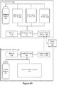
- FIGs 2A-2B are block diagrams illustrating a charging device 102, a battery powered device 104, and a client device 106 in accordance with some implementations.
- the charging device 102 is communicatively coupled to the battery powered device 104 and the client device 106 through a server system 108 (as described with reference to Figure 1A ).
- the charging device 102 is directly communicatively coupled to the battery powered device 104 and the client device 106 (as described with reference to Figure 1B ).
- the charging device 102 is configured to charge, and optionally discharge, a battery (or battery pack) 202.
- the battery 202 is configured for use in other battery powered devices 104 (e.g., configured for swapping with in-use battery 252).
- the charging device 102 includes control circuitry 204 (e.g., one or more processors) communicatively coupled with memory 208, communication circuitry 206, maintenance circuitry 212, discharging circuitry 214, and charging circuitry 216.
- the charging device 102 is configured to charge a variety of battery types (e.g., with varying chemistries, characteristics, specifications, and form factors).
- the communication circuitry 206 includes components for communicating with one or more remote electronic battery powered devices 104 and/or computing systems (e.g., server system 108 and/or client device 106).
- the communication circuitry 256 includes components for communicating with one or more charging devices 102 and/or computing systems (e.g., server system 108 and/or client device 106).
- the communication circuitry 206 and 256 includes one or more components for wireless communication (e.g., one or more antennas and/or transceivers) and/or one or more components for wired communication.
- the communication circuitry 206 and 256 includes, for example, hardware capable of data communications using any of a variety of custom or standard wireless protocols (e.g., IEEE 402.15.4, Wi-Fi, ZigBee, 6LoWPAN, Thread, Z-Wave, Bluetooth Smart, ISA100.5A, WirelessHART, MiWi, etc.) and/or any of a variety of custom or standard wired protocols (e.g., Ethernet, HomePlug, etc.), or any other suitable communication protocol, including communication protocols not yet developed as of the filing date of this document.
- the communication circuitry 206 and 256 includes one or more radios.
- the radios enable one or more radio communication networks in an Internet of things (IOT) environment, and enable charging device(s) 102 and battery powered device(s) 104 to communicate with other devices.
- the radios are capable of data communications using any of a variety of custom or standard wireless protocols (e.g., IEEE 402.15.4, Wi-Fi, ZigBee, 6LoWPAN, Thread, Z-Wave, Bluetooth Smart, ISA100.5A, WirelessHART, MiWi, etc.).
- memories 208 and 258 include high-speed random access memory, such as DRAM, SRAM, DDR RAM, or other random access solid state memory devices; and, optionally, include non-volatile memory, such as one or more magnetic disk storage devices, one or more optical disk storage devices, one or more flash memory devices, or one or more other non-volatile solid state storage devices.
- the memories 208 and 258, or alternatively the respective non-volatile memory within the memories 208 and 258, include respective non-transitory computer-readable storage mediums.
- the memories 208 and 258, or the respective non-transitory computer-readable storage mediums of the memories 208 and 258, store battery data such as state-of-charge information, battery health information, battery temperature information, battery location information, battery usage information, and the like (e.g., including battery management table 800, Figure 8A , and/or device management table 810, Figure 8B ).
- the maintenance circuitry 212 includes components for measuring characteristics of the batteries 202 (e.g., during charging and discharging), such as voltage levels, current levels, impedance levels, and the like. In some implementations, the maintenance circuitry 212 includes one or more sensors for determining status of the batteries 202, such as a temperature sensor to determine an operating temperature of the batteries 202.
- the discharging circuitry 214 includes components for discharging batteries 202. In some implementations, the discharging circuitry 214 includes components for discharging a variety of battery types (e.g., based on the chemistry of each battery type). In some implementations, the discharging circuitry 214 includes one or more resistors, diodes, or other elements configured to drain charge from the batteries 202. In some implementations, the discharging circuitry 214 includes one or more light emitting diodes (LEDs) for discharging the batteries 202 and providing feedback to a user of the charging device 102. In some implementations, the charging device 102 does not include the discharging circuitry 214, but rather utilizes self discharge functions of the batteries 202 to discharge the batteries.
- LEDs light emitting diodes
- the charging circuitry 216 includes components for charging batteries 202. In some implementations, the charging circuitry 216 includes components for charging a variety of battery types (e.g., based on the chemistry of each battery type).
- control circuitry 204 includes one or more processing units (also referred to as processors, microprocessors, and central processing units) which govern charging and discharging of the batteries 202 (e.g., based on information received from the communication circuitry 206 and/or the maintenance circuitry 212).
- processing units also referred to as processors, microprocessors, and central processing units
- the charging device 102 further includes a switching component and the control circuitry 204 controls the switching component to govern which of the charging, discharging, and maintenance circuits are coupled to the batteries 202 at a given time.
- control circuitry 254 includes one or more processing units (also referred to as processors, microprocessors, and central processing units) which govern device-specific operations of the battery powered device 104.
- the battery powered device 104 also includes device-specific circuitry 260 for executing the device-specific operations.
- the device-specific circuitry 260 may include image processing circuitry governed by models stored in memory 258 and executed by control circuitry 254.
- the control circuitry 254 is configured to process communications received by communication circuitry 256 (e.g., requests for battery life information of one or more in-use batteries 252).
- the control circuitry 254 is further configured to govern battery monitoring circuitry (not shown) in order to respond to battery life information requests (e.g., by obtaining battery life information of an in-use battery 252 and causing the battery life information to be transmitted to a charging device 102 through communication circuitry 256).
- FIG. 3 is a flow diagram illustrating a method 300 of battery management in accordance with some implementations.
- the method 300 is performed by a charging device (e.g., a charging device 102), an electronic device (e.g., a battery powered device 104), a client device (e.g., the client device 106), and/or a server system (e.g., the server system 108).
- a charging device e.g., a charging device 102
- an electronic device e.g., a battery powered device 104
- a client device e.g., the client device 106
- a server system e.g., the server system 108.
- the operations of the method 300 described herein are interchangeable, and respective operations of the method 300 are performed by any of the aforementioned devices or systems.
- the method 300 is governed by instructions that are stored in a non-transitory computer-readable storage medium and that is executed by one or more processors or controllers of a device, such as the control circuitry 204 and 254.
- a battery management system e.g., a system that includes a battery charging device, one or more battery powered electronic devices, and/or a server.
- the battery management system obtains (302) battery life information (BLI) associated with a first battery, such as a battery being used in a battery powered electronic device (e.g., in-use battery 252, battery powered device 104).
- BLI battery life information
- the battery management system obtains the BLI by sending a request to a battery powered device to acquire the BLI.
- the server system 108 or the battery charging device 102 sends the request to the battery powered device 104.
- the battery powered device is a battery powered device 104.
- the battery powered device is a camera, hazard detector, doorbell, display, assistant device, or security device.
- the request is sent via one or more networks (e.g., network(s) 110, Figure 1A ).
- the request is sent via device-to-device communication (e.g., as illustrated in Figure 1B ).
- the battery or the battery powered device using the battery receives the request and responds by sending BLI to the battery management system.
- the battery or the battery powered device using the battery includes communication circuitry (e.g., 256), control circuitry (e.g., 254), memory (e.g., 258), and control circuitry (e.g., 254).
- the control circuitry includes diagnostic circuitry configured to determine battery charging and/or discharging characteristics.
- the BLI is sent in response to the request.
- the BLI includes state-of-charge and/or state-of-health information for the in-use battery.
- the BLI is relayed to the battery management system via one or more networks and/or one or more server systems.
- the BLI is sent from the battery powered device to a server system (e.g., server system 108) via one or more networks and then is sent from the server system to a charging device (e.g., charging device 102).
- the BLI is received from a server system communicatively coupled to the battery powered device.
- the battery powered device uploads the BLI as part of an event notification or other status report with the server.
- the battery powered device routinely (periodically) uploads the BLI to a server system and/or charging device.
- the battery charging device includes a wireless radio component (e.g., communication circuitry 206, Figures 2A-2B ), and the BLI is received via the wireless radio component.
- the BLI is stored by the battery management system (e.g., in memory 208 and/or memory in the server system 108 or client device 106).
- the BLI is utilized to update one or more tables maintained by the battery management system (e.g., the battery management table 800 and/or the device management table 810 described below with reference to Figures 8A and 8B ).
- the battery management system obtains (303) battery information for a second battery, such as a charging battery that is electrically coupled to a battery charging device (e.g., charging battery 202, charging device 102), where the charging battery is configured for use in the battery powered device.
- a battery charging device e.g., charging battery 202, charging device 102
- the charging battery is configured for use in the battery powered device.
- at least a portion of the battery information for the charging battery is obtained from the charging battery.
- the charging battery sends at least a portion of the battery information to the battery management system.
- the battery charging device generates the battery information for the charging battery based on charging/discharging of the charging battery (e.g., as measured by the maintenance circuitry 212, Figures 2A-2B ).
- the battery information includes at least one of: charge capacity information, voltage level information, temperature information, and optimal charge range information. In some implementations, the battery information includes state-of-charge information and/or state-of-health information for the charging battery. In some implementations, the battery information is stored by the battery management system (e.g., in memory 208 and/or memory in the server system 108 or client device 106).
- the battery management system uses the battery information of the charging battery to update one or more tables maintained by the battery management system (e.g., the battery management table 800 and/or the device management table 810 described below with reference to Figures 8A and 8B ).
- at least a portion of the battery information for the charging battery is determined based on monitoring charging and discharging of the charging battery (e.g., monitored by a charging device 102 and/or a battery powered device 104).
- the battery management system e.g., a charging device 102 performs a maintenance routine (e.g., utilizing the maintenance circuitry 212) with charging and discharging phases on the charging battery to obtain at least a portion of the battery information.
- the maintenance routine is performed periodically (e.g., once per day, once per week, once per month). In some implementations, the maintenance routine is performed in accordance with a battery being docked to the battery charging device.
- the battery management system maintains a battery characterization table (e.g., battery management table 800, described below with reference to Figure 8A ), the battery characterization table including a first entry for the in-use battery and a second entry for the charging battery.
- the battery management system updates the first entry based on the BLI of the in-use battery and updates the second entry based on the battery information for the charging battery.
- the battery management system makes a battery health determination and, if needed, recommends disposal of old batteries and purchase of new batteries.
- the battery characterization table is stored at the charging device and/or a server system.
- the battery management system obtains (304) user demand information (UDI) associated with the in-use battery, or associated with a battery powered device being powered by the in-use battery.
- UDI user demand information
- the UDI is included in a notification from a user (e.g., via client device 106) of the battery powered device.
- the notification includes one or more of user schedule information, user calendar information, and/or information indicating a predicted usage of the battery powered device by the user (e.g., the user indicates he or she will be going on vacation and not using the device).
- the battery management system receives UDI in response to the user setting or updating one or more of a battery replacement schedule, a device priority, a user event, and/or a user calendar (e.g., affordances 706-712 described below with reference to Figure 7 ).
- the UDI includes user habit information, such as whether the user habitually changes batteries when 0%, 10%, or 30% of charge remains. In some implementations, the UDI includes user preferences, such as a preference to change batteries at 30%, 20%, or 10% of remaining charge. In some implementations, the UDI is obtained by storing information related to the user's response to prior battery notifications and remaining charge levels when the user previously swapped batteries.
- the battery management system causes (306) the charging battery's state of charge to be stepped up so that it is fully charged by the time the user swaps the batteries (e.g., if the habit or preference information indicates the user will return to the battery powered device at a certain time, or if the habit or preference information indicates that the user is likely to swap the batteries early).
- the battery management system causes the charging battery's state of charge to be stepped down to preserve battery performance if, for example, the habit or preference information indicates that the user will not use the battery powered device for a certain amount of time.
- the UDI indicates a user will be away from the battery powered device 104 during a particular time period, and the battery management system sends a notification to the user to swap the in-use and charging batteries prior to the particular time period.
- the user indicates that he or she will be going on vacation and is prompted to swap the batteries before leaving (e.g., so that the in-use battery is not fully depleted while the user is away).
- the battery management system causes (306) the charging battery's state of charge to be stepped up so that it is fully charged by the time the user receives the prompt to swap the batteries.
- the UDI indicates a user desire to install the charging battery in the battery powered device 104 at a particular time (e.g., the user requests a swap).
- the UDI is sent in response to the user setting or updating a battery replacement schedule that includes the in-use battery and/or charging battery.
- the battery management system causes (306) the charging battery's state of charge to be stepped up so that it is fully charged by the particular time, or by a replacement time indicated by the battery replacement schedule.
- the battery management system adjusts (306) the state of charge and/or the charging rate of the charging battery based on the BLI and/or the UDI associated with the in-use battery. For example, if the BLI of the in-use battery (e.g., in-use battery depletion time or state of charge) is over a threshold (306A), the battery management system maintains the state of charge of the charging battery in a longevity window (e.g., preferred range 402 as described below with reference to Figure 4A ).
- a longevity window e.g., preferred range 402 as described below with reference to Figure 4A .
- the battery management system steps up the state of charge of the charging battery so that the charging battery is fully charged, or close to fully charged (e.g., the charge level of Battery 2 between times T 2 and T 3 as described below with reference to Figure 4A ).
- the battery management system accounts for the UDI associated with the in-use battery (306C). For example, if the BLI is above a threshold (306A) the battery management system may bring the charging battery out of the longevity window and step up the state of charge if the UDI indicates a user is likely to swap batteries before the BLI of the in-use battery has a chance to drop below the threshold (306B). Likewise, if the BLI is below a threshold (306B), the battery management system may bring the state of charge of the charging battery back down to the longevity window if the UDI indicates the user will not use the device for a relatively long time (e.g., for more than a threshold amount of time). That way, the charging battery is not kept fully charged for an unnecessary amount of time.
- a threshold e.g., for more than a threshold amount of time
- adjusting the charging rate includes ceasing to charge the charging battery (e.g., in accordance with a determination that the in-use battery will not deplete within a predetermined amount of time, such as 3 days, 1 week, 2 weeks, or 1 month). In some implementations, adjusting the charging rate includes discharging the charging battery (e.g., to bring it back into a preferred charge range for long-term storage). In some implementations, the charging rate is adjusted based on an amount of charge in the in-use battery and/or a rate of depletion of the in-use battery (e.g., as illustrated below in Figures 4A-4C ). In some implementations, the charging rate is based on a temperature of the battery. In some implementations, the battery management system ensures that the charging rate complies with relevant safety standards, such as Japan Electronics and Information Technology Industries Association (JEITA) standards.
- JEITA Japan Electronics and Information Technology Industries Association
- the BLI indicates that the in-use battery will deplete by a particular time (e.g., BLI is less than a threshold, as in operation 306B).
- the battery management system sets the charging rate (steps up the state of charge) so that the charging battery will be fully charged by or at the particular time.
- the charging rate is set so that the charging battery will be fully charged at a preset time in advance of depletion of the in-use battery. For example, the charging battery is charged so that it will be fully charged 1 hour, 1 day, or 3 days before the in-use battery depletes.
- the preset time is based on the UDI such as user preferences (e.g., how soon before depletion does the user prefer to swap batteries) and user history (e.g., on average how soon before depletion has the user historically swapped batteries).
- user preferences e.g., how soon before depletion does the user prefer to swap batteries
- user history e.g., on average how soon before depletion has the user historically swapped batteries.
- fully charged means above a predetermined threshold amount of charge (e.g., greater than 80%, 90%, or 95%) of the battery's current charge capacity. For example, a battery is considered to be fully charged if it is within 10% of its maximum charge capacity (which may decrease with use and time).
- depleted means below a predetermined threshold amount of charge (e.g., less than 20%, 10%, or 5%) of the battery's charge capacity. For example, a battery is considered to be depleted if it has less than 10% of its maximum charge capacity.
- the BLI indicates that the in-use battery will deplete at the particular time.
- the charging rate is adjusted so that the charging battery will be fully charged at the particular time.
- the BLI indicates an estimated depletion time for the in-use battery, and if the depletion time is over a threshold (306A), the battery management system maintains the charging battery at a charge level in a longevity window (e.g., below a predefined threshold and/or within a preferred charge range) until a predefined amount of time before the estimated depletion time (e.g., until 5 hours, 12 hours, or 2 days before the estimated depletion time). Once the predefined amount of time before the estimated depletion time is less than a threshold amount (306B), the battery management system steps up the state of charge of the charging battery (e.g., as illustrated below in Figures 4A-4C ).
- the BLI indicates a time period for depletion of the in-use battery (or the battery management system determines a time period for depletion of the in-use battery based on the BLI).
- the battery management system determines a time period for depletion of the in-use battery based on the BLI.
- the battery management system determines a time period for depletion of the in-use battery based on the BLI.
- the battery management system forgoes charging the charging battery.
- the battery management system charges the charging battery at a rate sufficient to fully charge the battery by the end of the time period for depletion.
- the battery information of the charging battery indicates a current charge level for the charging battery (or the battery management system obtains a current charge level for the charging battery based on the battery information associated with the charging battery).
- the battery management system actively drains charge from the charging battery (e.g., utilizing discharging circuitry 214, Figures 2A-2B ) to that required for maintaining the longevity window.
- actively draining charge comprises electrically coupling the charging battery to a transistor and/or resistor to discharge the battery.
- actively draining charge comprises electrically coupling the charging battery to an LED of the charging device.
- the charging battery is passively discharged (e.g., the charging battery is discharged via a self discharge mechanism of the charging battery).
- the predefined threshold charge amount is based on a chemistry of the charging battery.
- the battery management system generates (308) a user notification (e.g., a notification 504, 550, 552, or 554, Figures 5A-5B ) based on the BLI and/or the UDI associated with the in-use battery.
- the user notification includes an estimated depletion time for the in-use battery.
- the user notification is generated by the battery powered device, the server system, or the battery charging device.
- the user notification is, or includes, at least one of: an SMS, a calendar event, an alert in an assistant application, and an email.
- the user notification is displayed within a battery life user interface (e.g., the user interfaces 600 and/or 700 as described below with reference to, Figures 6A-6B and 7) indicating a battery charge level of the in-use battery.
- the battery management system receives BLI for a second in-use battery (a battery in use in a second battery powered device), and adjusts the charging rate for the charging battery based on the BLI of the first in-use battery and the BLI of the second in-use battery.
- the battery management system manages multiple batteries in use in multiple battery powered devices (e.g., as described below with reference to Figures 4C , 6A-6B, 7, and 8A-8B ).
- the user has two battery powered cameras, a battery powered doorbell, and a battery powered smoke detector that all use the same type of batteries.
- the user also has a battery charger and a spare battery.
- the battery management system tracks the charge levels of the in-use batteries and charges the spare battery accordingly.
- the battery management system notifies the user when one of the battery powered devices is in need of a battery swap (e.g., 20%, 10%, or 5% of full charge remaining).
- the BLI of the first in-use battery indicates a first depletion time and the BLI of the second in-use battery indicates a second depletion time, and the charging rate of the charging battery is adjusted so as to fully charge the charging battery before the first or second depletion times.
- FIGS 4A-4C illustrate example charging sequences for battery systems in accordance with some implementations.
- the charging device 102 is electrically coupled to battery 2 and is in communication with the battery powered device 104-1 using battery 1.
- the charging device 102 is adjusting charging rates for battery 2 based on battery information of battery 1, received from the battery powered device 104-1.
- adjusting a charging rate includes adjusting a voltage and/or current supplied to the battery by the charging device 102.
- battery 2 in the charging device 102 is below a preferred charge range 402 for the battery.
- the preferred charge range 402 is based on chemistry of battery 2.
- the preferred charge range 402 is based on a battery type of battery 2.
- the preferred charge range 402 is prescribed by the manufacturer of battery 2.
- battery 1 is at full charge (e.g., batteries 1 and 2 were swapped just prior to To).
- battery 2 is charged up so that it is within the preferred charge range 402.
- battery 2 is charged up at, or near (e.g., within 80%, 90%, or 95% of) a maximum charging rate for battery 2 so as to bring the charge level of battery 2 within the preferred range 402 as quickly as possible.
- battery 2 is charged up at, or near (e.g., within 80%, 90%, or 95% of) a maximum charging rate for the charging device 102 so as to bring the charge level of battery 2 within the preferred range 402 as quickly as possible.
- battery 2 is maintained within the preferred range 402 because battery 1 has a charge level above the threshold Ci.
- the charge level of battery 1 drops below the threshold charge level, Ci, and corresponding battery 2 is charged up beyond the preferred range 402 toward full charge (in preparation for swapping it into the battery powered device 104-1).
- battery 2 is charged up between times T 2 and T 3 at a maximum charging rate (e.g., as specified by the battery manufacturer or the capabilities of the charging device 102).
- battery 2 is charged up between times T 2 and T 3 at a rate corresponding to a drain rate of battery 1, so that battery 2 is fully charged just before battery 1 depletes (e.g., days, hours, or minutes before battery 1 depletes).
- battery 1 is nearly depleted and battery 2 is at full charge in preparation for an imminent swap.
- the user is prompted to switch the batteries at time T 3 .
- the user is prompted by the battery powered device 104-1 (e.g., via a user interface on the camera), by the charging device 102 (e.g., via a user interface on the charging device 102), and/or is prompted via notification at a client device, such as the user's mobile phone.
- the charging device 102 is electrically coupled to battery 2 and is in communication with the battery powered device 104-1 using battery 1 and a client device 106.
- the charging device 102 in Figure 4B is adjusting charging rates for battery 2 based on battery information from the battery powered device 104-1 and user information from the client device 106.
- T 0 battery 2 in the charging device 102 is below a preferred charge range 402 for the battery and battery 1 is at full charge.
- T 1 battery 2 is charged up sufficiently to have a charge level within the preferred charge range 402.
- battery 2 is charged up beyond the preferred range 402 as battery 1 depletes (e.g., the rate of charge of battery 2 is proportional to the rate of discharge of battery 1).
- a user notification is received from the client device 106 indicating that the battery powered device 104-1 is going to be disabled for an extended period of time (e.g., the user is moving to a new location and is powering the camera down while the user moves).
- battery 2 is discharged (between time T 2 to time T 3 ) so that its charge level is brought back down to the preferred range 402.
- battery 2 is discharged at, or near (e.g., within 80%, 90%, or 95% of) a maximum discharge rate for battery 2 and/or the charging device 102 so as to bring the charge level for battery 2 back within the preferred range 402 as quickly as possible.
- the charging device 102 is electrically coupled to battery 2 and is in communication with the battery powered device 104-1 using battery 1 and a battery powered device 104-2 using battery 3.
- the charging device 102 in Figure 4C is adjusting charging rates for battery 2 based on battery information from the battery powered devices 104-1 and 104-2.
- T 1 battery 2 in the charging device 102 is below a preferred charge range 402 for the battery and batteries 1 and 2 are at full charge.
- T 1 battery 2 is charged up sufficiently to have a charge level within the preferred charge range 402.
- the charging device 102 receives battery information from the battery powered device 104-2 (or from battery 3) that includes a current amount of charge in battery 3 as well as a drain rate for battery 3.
- battery 2 is charged up to full charge based on a high drain rate for battery 3.
- the current charge amount and the drain rate of battery 3 are used to determine an estimated depletion time for battery 3, and the charging rate for battery 2 is adjusted so that battery 2 is fully charged before the estimated depletion time of battery 3.
- FIG. 5A illustrates an example battery notification in accordance with some implementations.
- a client device 106 includes a display 500 (e.g., a touch screen) with a graphical user interface 502.
- the graphical user interface 502 is a lock screen of the client device with displayed user notifications.
- the graphical user interface 502 is an application home screen or notification screen.
- the graphical user interface 502 includes a battery notification 504 for the user (e.g., an SMS notification, an email notification, or an application notification).
- the battery notification 504 includes information regarding which device requires a battery swap and whether there is a replacement battery ready.
- the battery notification 504 includes an estimated depletion time for the battery in the device ("Backyard Camera") (e.g., 2 hours, 3 days, etc.).
- FIG. 5B illustrates other example battery notifications in accordance with some implementations.
- the notification 550 includes information regarding a battery needing charging and the device ("Backyard Camera") in which the battery is currently installed.
- the notification 550 also includes information regarding ordering additional batter(ies) to minimize device downtime.
- a shopping user interface is presented to the user with options to purchase batteries and battery charging device.
- a calendar event is added to the user's calendar to prompt the user to charge the battery in the Backyard Camera, e.g., at a time that is determined to be convenient to the user such a time when the user will be in the vicinity of the Backyard Camera and does not have a preexisting engagement scheduled.
- the notification 550 is displayed in accordance with a determination that the user does not have a back-up (replacement) battery to swap into the Backyard Camera, and the notification 504 is displayed in accordance with a determination that the user does have a back-up (replacement) battery.
- the notification 552 includes information regarding a battery needing to be disposed of and a device in which the battery is currently installed.
- the battery is determined to by near end-of-life based on battery information obtained from the battery or determined based on battery charge and/or discharge information (e.g., obtained from the Backyard Camera and/or a charging device).
- the notification 552 includes links to disposal information for the current battery and ordering information for a new battery.
- a shopping user interface is presented to the user with options to purchase batteries and battery charging device.
- a disposal user interface is presented to the user with local battery disposal services and options.
- the notification 552 includes information regarding why the battery is considered to be near end-of-life (e.g., increased impedance and/or swell and lowered charge capacity).
- the battery management system e.g., the charging device or server system
- monitors state-of-health information for non-rechargeable and/or non-replaceable batteries e.g., an embedded battery in a hazard detector.
- the battery management system generates a notification, such as notification 552, when a non-rechargeable battery is determined to be at end-of-life.
- the battery management system generates a notification when a non-replaceable battery is determined to be at end-of-life.
- the notification regarding a non-replaceable battery at end-of-life includes options for ordering or acquiring a new device and/or options for disposing of the current device.
- the notification 554 includes information regarding a battery needing charging and the device in which the battery is currently installed. For example, the user is scheduled to leave for Kansas in six days and remain in Kansas for two weeks, whereas the battery in the Backyard camera is estimated to deplete in fourteen days. Therefore, a notification is sent to the user to replace the battery in the Backyard Camera prior to leaving for Kansas.
- the notification is generated by an assistant system based on information in the user's shared electronic calendar.
- the battery management system conveys the notification information to the user via an audio notification (e.g., utilizing a user interaction module 434).
- a user device with speakers may "read" the notifications 504, 550, 552, and 554 to the user.
- a user device with an assistant application or program also sometimes called an assistant device
- the battery management system audibly conveys the notification information to the user and lists actions a user may take, such as ordering new batteries or obtaining disposal information.
- a user device listens for a response from the user, such as a user selection of one of the listed actions, and responds accordingly (e.g., obtaining and audibly conveying disposal options to the user).
- Figures 6A-6B illustrate representative graphical user interfaces for battery management in accordance with some implementations.
- Figure 6A shows a graphical user interface 600 (e.g., displayed within an assistant application on the user's client device) that includes information on a plurality of battery powered devices 104.
- the user interface 600 is displayed in response to a user selection of a device list affordance within an assistant application.
- the user interface 600 is displayed in response to a user selection of a battery management affordance within an assistant application.
- each battery powered device 104 listed on the user interface 600 includes indication of a device type (e.g., camera, doorbell, thermostat, charging device), a device label, and battery information for batteries associated with each device.
- a device type e.g., camera, doorbell, thermostat, charging device
- a battery identifier is display, e.g., to assist users in tracking individual batteries.
- the Backyard Camera device 602 has a battery with a current charge level 603 of 95% of full charge
- the Porch Camera device 604 has a battery with a current charge level 605 of 70% of full charge
- the Doorbell device 606 has a battery with a current charge level 607 of 60% of full charge.
- the user interface 600 includes display of a state of the replacement battery 608 installed in a battery charging device 102.
- the replacement battery 608 is being maintained at a charge level 609 of 50% of full charge (e.g., within a preferred charge range for the battery).
- the replacement battery charging information includes a notice to the user that charging is suspended to extend battery life and an option for the user to override the charging device state and resume charging of the battery (e.g., so that the user may replace an in-use battery sooner than was calculated by the charging device 102 or battery management system).
- Figure 6B shows a graphical user interface 620 similar to the user interface 600 of Figure 6A , except that the Backyard Camera device 602 in Figure 6B has a battery with a current charge level 611 of 10% of full charge, and therefore a replacement recommendation 616 is displayed and the charging device 102 has fully charged (613) the replacement battery 608.
- the battery management system conveys the information of the user interface to the user via audio interactions (e.g., utilizing a user interaction module 434).
- a user may ask an assistant device to: (1) relay battery information for the user's battery powered devices, (2) relay a current state of the replacement battery, or (3) relay whether any battery powered devices are near depletion.
- the assistant device would relay the information shown in the user interfaces in Figures 6A-6B that is responsive to the user's query.
- the information is relayed to the user audibly and/or visibly and the user may interact via audio commands or selections within the user interface.
- the assistant device is the battery charging device, a hub device, a battery powered device 104, a mobile phone, a tablet, and the like.
- FIG. 7 illustrates a graphical user interface 700 for battery management in accordance with some implementations.
- the user interface 700 includes information regarding batter(ies) electrically coupled to (e.g., mounted on) a battery charging device 102.
- the user interface 700 further includes a plurality of affordances (e.g., software buttons) for user battery management.
- a charging device identified as charging device #1 is currently managing charging of a battery identified as battery #13.
- battery #13 is currently being maintained at a charge level 609 of 50% charge, e.g., because no in-use battery is near depletion.
- the user interface 700 in Figure 7 is intended as a non-limiting example.
- a subset or superset of the affordances and information shown in Figure 7 are presented to a user.
- one or more of the affordances shown in Figure 7 are presented to users on other user interfaces, such as the user interfaces shown in Figures 6A-6B .
- the user interface 700 is displayed in response to selection of a battery charging device affordance (or battery affordance) within an assistant application or battery management application. In some implementations, the user interface 700 is displayed as part of a home screen in a battery management application. In some implementations, the user interface 700 is displayed on a display of the battery charging device 102.
- the user interface 700 includes a full charge affordance 702 and a device batteries affordance 704.
- the charging device 102 charges battery #13 toward full charge (e.g., switches from a maintenance or discharge mode to a charging mode).
- charging the battery toward full charge includes charging the battery at a maximum charge rate for the battery or the battery charging device.
- a user interface is presented with information regarding batteries in-use in various associated electronic devices (e.g., the user interface 600 or 1050 is presented).
- the user interface 700 includes a recharge scheduling section with device priority affordance 706 and schedule affordance 708.
- a device listing user interface is presented where the user is enabled to rank the devices by priority.
- the user ranking is utilized to determine priority and/or scheduling of battery replacements. For example, if the doorbell 606 in Figure 6A is ranked as highest priority, and both the doorbell 606 and the porch camera 604 are near depletion, then the battery management system (e.g., battery charging device 102 and/or server system 108) will recommend that the user swap the battery in the doorbell 606 before swapping a battery in the porch camera 604.
- the battery management system e.g., battery charging device 102 and/or server system 108
- the battery management system will recommend swapping batteries for higher ranked devices at higher charge levels. For example, the battery management system may recommend swapping the battery for the doorbell ranked as highest priority when the in-use battery is at 30% charge. In this example, the battery management system may recommend swapping the battery for the doorbell ranked as second highest priority when the in-use battery is at 20% charge. As another example, the battery management system may recommend swapping the battery for the doorbell ranked as highest priority when the in-use battery is estimated to deplete in 7 days. In this example, the battery management system may recommend swapping the battery for the doorbell ranked as second highest priority when the in-use battery is estimated to deplete in 3 days.
- a scheduling user interface in response to a user selection of the schedule affordance 708, a scheduling user interface is presented to the user.
- the scheduling user interface enables a user to set and/or revise a battery charging (and swapping) schedule.
- the user may indicate how often, or on what days, the user prefers to exchange batteries in their battery powered electronic devices. Having a schedule helps prevent multiple devices from needing battery replacements at the same time and therefore can minimize downtime due to drained batteries. For example, the user may indicate that they wish to swap a camera's batteries on the first day of every second month and swap a doorbell's batteries on the fifteenth day of every third month.
- the user is provided with information regarding an estimated amount of time each battery with drain within a particular device. For example, the user is notified that a camera will drain a fully charged battery in approximately 4 months while a doorbell will drain a fully charged battery in approximately 1 year. Thus, the user is able to schedule dates that are within the estimated drain time for each battery and device.
- the estimated drain time is based on the user's usage patterns, the battery's health, and the like.
- the user interface 700 includes an event scheduling section with an input event affordance 710 and calendar affordance 712.
- an event user interface in response to a user selection of the input event affordance 710, an event user interface is presented to the user.
- the event user interface enables a user to input information regarding an upcoming event that will impact battery usage and/or charging. For example, the user may indicate that he or she is going on vacation for several weeks and thus a doorbell will be disabled or in low power mode for that time. Therefore, the battery management system (e.g., the battery charging device 102 and/or the server system 108) extends an estimated drain date for the doorbell by several weeks.
- the user may indicate that he or she is going to keep an indoor camera active continuously while he or she is away (rather than disabling it during the day). Therefore, the battery management system reduces an estimated drain date for the indoor camera by several weeks. As another example, the user indicates that he or she will be away on dates that would otherwise be battery swap dates (e.g., dates when an in-use battery is drained or dates that the user has scheduled to swap batteries). In this example, the battery management system notifies the user to swap the battery prior to the user leaving, or reschedule the swap date (e.g., for after the user returns).
- batteries swap dates e.g., dates when an in-use battery is drained or dates that the user has scheduled to swap batteries.
- a calendar interface in response to a user selection of the calendar affordance 712, a calendar interface is presented to the user.
- the calendar interface enables a user to import or share his or her electronic calendar (e.g., for the purposes of estimating drain times and scheduling battery swap dates).
- the calendar interface enables a user to input or revise calendar events (e.g., events impacting battery drain rates and/or scheduled battery swap dates).
- the user interface 700 includes a battery section with an add/remove battery affordance 714 and a view battery information affordance 716.
- a battery management user interface is presented to the user.
- the battery management user interface enables a user to add new batteries for the battery management system to track and management (e.g., add batteries the user has recently purchased).
- the battery includes a barcode (or other scannable information) and the battery management user interface enables a user to scan or capture the barcode so that the information is received by the battery management system.
- the battery management system receives new battery information from the battery charging device 102 or a battery powered electronic device once the battery is coupled to those devices.
- the battery management user interface enables a user to remove batteries from the battery management system (e.g., remove batteries the user has recently disposed of or given away).
- a battery information interface in response to a user selection of the battery information affordance 716, a battery information interface is presented to the user.
- the battery information interface enables a user to view or revise information on batteries tracked by the battery management system. For example, the user may be allowed to enter information regarding battery specifications, intended use, past usage, and the like.
- the battery information interface includes a battery management table (e.g., battery management table 800, Figure 8A ) and/or a device management table (e.g., the device management table 810, Figure 8B ).
- the battery management system conveys the information of the user interface to the user via audio interactions (e.g., utilizing a user interaction module 434).
- a user may ask an assistant device to relay: (1) a current state of the replacement battery, (2) current charge levels for the user's battery powered devices, (3) current device priorities, (4) current battery replacement schedule, or (5) battery information.
- a user may verbally instruct an assistant device to: (1) fully charge replacement battery, (2) display current battery levels, (3) adjust device priorities, (4) adjust the battery replacement schedule, (5) update a user's calendar, (6) add/remove batteries from tracking, or (7) display battery information.
- Figures 8A-8B illustrate representative tables for battery and device management in accordance with some implementations.
- Figure 8A shows a battery management table 800 that includes a listing of batteries in use and/or charging.
- the battery management table 800 includes, for each battery, a battery identifier, a device identifier for the device in which the battery is currently located, a current charge level, a maximum charge level, and an estimated life.
- the battery management table 800 includes a superset or subset of the information shown in Figure 8A .
- the battery management table 800 optionally includes impedance information, chemistry information, manufacturer specifications, and/or swell information.
- estimated life for each battery is displayed, but the maximum charge information is not.
- batteries are added to the table manually by a user. In some implementations, batteries are added to the table in response to a user scanning a barcode or other visual information for the battery. In some implementations, batteries are added to the table in response to deployment in a user's device (e.g., automatically and/or without user interaction). For example, the battery submits its information to the battery management system during deployment.
- the current charge level is obtained from the battery.
- the current charge level is estimated (e.g., by the device in which the battery is located or the server) based on battery characteristics and usage.
- the maximum charge information is estimated based on battery health information and/or characteristics (e.g., data obtained by a charging device 102 during a maintenance cycle), such as state-of-charge information, voltage values, temperature values, capacity, impedance, direct current resistance (DCR), and/or current values.
- the estimated life information is determined based on battery health information and/or characteristics (e.g., data obtained by a charging device 102 during a maintenance cycle).
- Figure 8B shows a device management table 810 that includes a listing of the user's battery powered devices.
- the device management table 810 includes, for each device, a device identifier, a device label, a current charge level, an estimated time until battery depletion, and priority level.
- the device management table 810 includes a superset or subset of the information shown in Figure 8B .
- the device management table 810 optionally includes a battery identifier for the battery in each device.
- the device label for each device is included, but the device identifier is not.
- the device priority is set or adjusted by the user (e.g., via the device priority affordance 706, Figure 7 ).
- the device labels are received from a user (e.g., via an assistant application or battery management application).
- the battery management table 800 and/or the device management table 810 is stored at (and maintained by) a charging device (e.g., the charging device 102). In some implementations, the battery management table 800 and/or the device management table 810 is stored at (and maintained by) a server (e.g., the server system 108).
- the following examples illustrate utilizing battery chemistry, user preferences, user usage patterns, scheduling information, and battery state-of-charge information to adjust charging rates and extend battery longevity in accordance with various implementations.
- Example 1 A first battery is in use in an electronic device and a second battery is mounted in a battery charging device.
- the first battery conveys that it is at more than 80% of full charge
- the second battery is maintained at around 50% of full charge (or within a preferred charge range based on the particular chemistry of the battery).
- the first battery may convey its state-of-charge information via an integrated state-of-charge chip and communication circuitry.
- the battery charging device utilizes a variety of charging modes for a replacement battery, e.g., based on state-of-charge information for the one or more in-use batteries.
- the charging modes optionally include one or more of: (1) a maintenance mode where the charging battery is maintained at partial charge (e.g., within a preferred charge range); (2) a measurement mode where the charging battery is charged/discharged to determine battery characteristics such as capacity, impedance, direct current resistance (DCR), and the like; (3) a charge-up mode where the charging battery is charged toward full charge in anticipate of immediate use; and (4) a charge-down mode where the charging battery is discharged (e.g., actively or passively), e.g., in response to updated information indicating that immediate use is unlikely.
- a maintenance mode where the charging battery is maintained at partial charge (e.g., within a preferred charge range)
- a measurement mode where the charging battery is charged/discharged to determine battery characteristics such as capacity, impedance, direct current resistance (DCR),
- Example 2 A battery with NCA chemistry (e.g., a lithium nickel cobalt aluminum oxide battery) at 2150 mAh minimum capacity (C-rate) with a top of charge voltage of 4.2 V and cut-off voltage of 2.5 V.
- the battery specifications include a standard charge of 1375 mA and maximum discharge of 5500 mA, with a preferred cell storage voltage range of 3.75 V (57% SOC) to 3.55 V (24% SOC).
- the battery specifications are provided to a battery management system.
- the battery specifications are stored in a database accessible to the battery management system, or are transmitted to the battery management system as part of a battery registration process.
- the data provided to the battery management system optionally includes: a cell date code, a pack date code, and a timestamp of when battery is put into ship mode, in addition to the cell chemistry specifications.
- the following triggers for a cell maintenance cycle are used.
- SOC is stepped down from 100% to 80% via discharge path at a rate that does not exceed the maximum rated discharge current and a rate that does not exceed over discharge current protection within a protection circuit module (PCM).
- PCM protection circuit module
- Maintenance cycle for capacity check and DCR check (1 C pulse for 1 second) is performed via a five-hour (C/5) discharge down to 3.0 V (or near system shutdown) and a constant current charge C/5 to 4.2 V with a twentyhour (C/20) charge termination.
- C/5 to near shut-down voltage e.g., 3.2 V
- the above steps are then repeated until indication of imminent use is received.
- Example 3 A battery with LCO chemistry (e.g., a lithium cobalt oxide battery) at 560 mAh minimum capacity (C-rate) with a top of charge voltage of 4.2 V and cut-off voltage of 3.0 V.
- the battery specifications include a standard charge of 112 mA and maximum discharge of 560 mA, with a preferred cell storage voltage range of 3.9 V (65% SOC) to 3.8 V (47% SOC).
- the battery specifications are provided to a battery management system.
- the battery specifications are stored in a database accessible to the battery management system, or are transmitted to the battery management system as part of a battery registration process.
- the data provided to the battery management system optionally includes: a cell date code, a pack date code, and a timestamp of when battery is put into ship mode, in addition to above cell chemistry specifications.
- the following triggers for a cell maintenance cycle are used.
- SOC is stepped down from 100% to 80% via discharge path at a rate that does not exceed the maximum rated discharge current and a rate that does not exceed over discharge current protection within PCM.
- SOC is stepped down from 80% to within cell storage range of 3.9 V (65% SOC) and 3.8 V (47% SOC).
- a maintenance cycle is performed for capacity check and DCR check (1 C pulse for 1 second) via a C/5 discharge down to 3.0 V (or near system shutdown) and constant current charge at C/5 to 4.2 V with a C/20 charge termination.
- Adjusting charging rates and maintenance cycles based on battery chemistry allows a user access to a fully charged reserve battery pack on the charger device when needed, while maintaining battery longevity.
- Example 4 A user has a battery powered device (e.g., a wireless camera) with a first removable battery pack and a charging device with a second removable battery pack. While the first battery pack is between 80% and 50% SOC, the second battery pack is maintained at around 50% SOC (or in accordance with cell long term storage recommendations for the particular chemistry type). In some implementations, the second battery pack is charged to full after the first battery pack is below a threshold SOC (e.g., 20%, 30%, or 50% SOC), where the threshold SOC is based on learning the user's preferences and usage patterns. Learning the user's preferences and usage patterns enables a high probability for the user to swap in the second battery while it is at (or near) full charge. In this scenario, the user may not even be aware of the battery maintenance operations carried out by the charging device.
- a threshold SOC e.g. 20%, 30%, or 50% SOC
- the user could activate a "vacation" mode for the user's home (or one or more battery powered devices) or schedule a vacation on the user's electronic calendar.
- the charging device or a server system in communication with the charging device, generates a notification for the user to swap out an in-use battery pack for a charged battery (e.g., before the in-use battery pack would otherwise be swapped out) to ensure that the battery powered device (e.g., a security camera) does not run out of charge during the vacation period.
- the charging device adjusts charging rates for the second battery pack to ensure that it is ready to be swapped in prior to the vacation period.
- Example 5 A user has a battery powered device (e.g., a wireless camera) with a first removable battery pack and a charging device with a second removable battery pack. While the first battery pack is below 50% SOC, the second battery pack is maintained around 80% SOC, and charged to full based on learning behavior of the user's inclination to swap out battery packs. This enables a high probability that the user swaps in the second battery while it is at, or near, full charge.
- a battery powered device e.g., a wireless camera
- Example 6 A user has a battery powered device (e.g., a wireless camera) with a first removable battery pack and a charging device with a second removable battery pack.
- the user checks on the status of the second battery pack while it is within a charge/discharge maintenance cycle.
- the customer is notified (e.g., via an application on the user's mobile device) of the current maintenance cycle.
- the user indicates they are need of the second battery pack immediately (e.g., via a corresponding button or other affordance), and the charging device halts the charge/discharge maintenance cycle and instead prepares the battery to be fully charged.
- a charge timer and/or estimated charge completion time is presented to the user (e.g., via the application on the user's mobile device).
- Example 7 A user has a battery powered device (e.g., a wireless camera) with a first removable battery pack and a charging device with a second removable battery pack.
- the user checks on the status of second battery pack while it is maintained at 50% SOC for battery longevity.
- the user is able to use a software button press (or other affordance) to request that the second battery pack be fully charged within a timer period.
- the user is notified when the second battery pack is at full charge (ready to be swapped with the first battery pack).
- the second battery pack is brought back down from full charge (e.g., via a discharge mode or maintenance cycle).
- Example 8 A user has a battery powered device (e.g., a wireless camera) with a first removable battery pack and a charging device with a second removable battery pack.
- the user swaps out the first battery pack for the second battery pack without checking the charge status of the second battery pack.
- the user is notified if the swap occurs at a time when the second battery pack is not near full charge (e.g., in a maintenance cycle or during a low SOC long term storage state).
- the charging device charges the first battery pack to full (e.g., without maintaining it in a preferred charge range).
- the user allows the first battery pack to fully charge then swaps out with second battery pack during the relatively short charge period. This ensures maximum operating use of the device within a single charge, if an unintentional battery swap has taken place with non-optimal battery life expectations for the device.
- stages that are not order dependent may be reordered and other stages may be combined or broken out. While some reordering or other groupings are specifically mentioned, others will be obvious to those of ordinary skill in the art, so the ordering and groupings presented herein are not an exhaustive list of alternatives. Moreover, it should be recognized that the stages could be implemented in hardware, firmware, software or any combination thereof.
- first, second, etc. are, in some instances, used herein to describe various elements, these elements should not be limited by these terms. These terms are only used to distinguish one element from another.
- a first camera could be termed a second camera, and, similarly, a second camera could be termed a first camera, without departing from the scope of the various described implementations.
- the first camera and the second camera are both cameras, but they are not the same camera unless explicitly stated as such.
- the term “if' is, optionally, construed to mean “when” or “upon” or “in response to determining” or “in response to detecting” or “in accordance with a determination that,” depending on the context.
- the phrase “if it is determined” or “if [a stated condition or event] is detected” is, optionally, construed to mean “upon determining” or “in response to determining” or “upon detecting [the stated condition or event]” or “in response to detecting [the stated condition or event]” or “in accordance with a determination that [a stated condition or event] is detected," depending on the context.
Landscapes
- Engineering & Computer Science (AREA)
- Power Engineering (AREA)
- Charge And Discharge Circuits For Batteries Or The Like (AREA)
- Health & Medical Sciences (AREA)
- General Health & Medical Sciences (AREA)
- Medical Informatics (AREA)
Claims (15)
- Verfahren, umfassend:
bei einem Batterieladegerät (102), das einen oder mehrere Prozessoren und einen Speicher (208) beinhaltet:Empfangen einer ersten Batterielebensdauerinformation für eine erste Batterie (252), die in einer elektronischen Vorrichtung (104; 104-1 - 104-m) installiert ist;Empfangen von Benutzeranforderungsinformationen für die elektronische Vorrichtung (104; 104-1 - 104-m);basierend auf der ersten Batterielebensdauerinformation und den Benutzeranforderungsinformationen, Anpassen einer Laderate für eine zweite Batterie (202), die elektrisch mit der Batterieladevorrichtung (102) zum Laden gekoppelt ist, wobei die zweite Batterie (202) zur Verwendung in der elektronischen Vorrichtung (104; 104-1 - 104-m) konfiguriert ist. - Verfahren nach Anspruch 1, wobei die erste Batterielebensdauerinformation angibt, dass sich die erste Batterie (252) bis zu einem bestimmten Zeitpunkt entladen wird; und
wobei das Anpassen der Laderate das Einstellen der Laderate umfasst, sodass die zweite Batterie (202) zu dem bestimmten Zeitpunkt vollständig geladen ist. - Verfahren nach einem der Ansprüche 1-2, ferner umfassend:Ermitteln einer Zeitdauer für die Entladung der ersten Batterie basierend auf der ersten Batterielebensdauerinformation;gemäß einem Ermitteln, dass die Zeitdauer für die Entladung eine vorbestimmte Zeitspanne überschreitet, Verzichten auf das Laden der zweiten Batterie; undgemäß einem Ermitteln, dass die Zeitdauer für die Entladung die vorbestimmte Zeitspanne nicht überschreitet, Laden der zweiten Batterie mit einer Rate, die ausreicht, um die Batterie bis zum Ende der Zeitdauer für die Entladung vollständig zu laden;optional ferner umfassend:Erhalten eines aktuellen Ladezustands für die zweite Batterie (202); undgemäß einem Ermitteln, dass der aktuelle Ladezustand eine vorbestimmte Schwellenladungsmenge überschreitet, und einem Ermitteln, dass die Zeitdauer für die Entleerung die vorbestimmte Zeitspanne überschreitet, aktives Entleeren der zweiten Batterie (202).
- Verfahren nach einem der Ansprüche 1-3, wobei das Empfangen von Benutzeranforderungsinformationen für die elektronische Vorrichtung (104; 104-1 - 104-m) das Empfangen einer Benachrichtigung von einem Benutzer der elektronischen Vorrichtung beinhaltet, wobei optionaldie Benachrichtigung eine vorhergesagte Nutzung der elektronischen Vorrichtung (104; 104-1 - 104- m) durch den Benutzer angibt,die Benachrichtigung einen Benutzerwunsch angibt, die zweite Batterie (202) zu einem bestimmten Zeitpunkt in der elektronischen Vorrichtung (104; 104-1 - 104-m) zu installieren, oderdie Benachrichtigung angibt, dass ein Benutzer während einer bestimmten Zeitdauer von der elektronischen Vorrichtung (104; 104-1 - 104-m) abwesend sein wird; unddas Verfahren ferner das Senden einer Benachrichtigung an den Benutzer umfasst, die erste und die zweite Batterie (252, 202) vor der bestimmten Zeitdauer auszutauschen.
- Verfahren nach einem der Ansprüche 1-4, wobei die erste Batterielebensdauerinformation eine geschätzte Entladezeit für die erste Batterie (252) angibt; und
das Verfahren ferner ein Halten der zweiten Batterie (202) auf einem Ladezustand unterhalb eines vordefinierten Schwellenwerts bis zu einer vordefinierten Zeitspanne vor der geschätzten Entladezeit umfasst. - Verfahren nach einem der Ansprüche 1-5, wobei die Batterieladevorrichtung (102) eine drahtlose Funkkomponente beinhaltet, und wobei die erste Batterielebensdauerinformation über die drahtlose Funkkomponente empfangen wird.
- Verfahren nach einem der Ansprüche 1-6, ferner umfassend das Senden einer Anforderung an die elektronische Vorrichtung (104; 104-1 - 104-m) zum Erfassen von Batterielebensdauerinformationen; und
wobei die erste Batterielebensdauerinformation in Reaktion auf die Anforderung empfangen wird. - Verfahren nach einem der Ansprüche 1-7, ferner umfassend das Erhalten von Batterieinformationen für die zweite Batterie (202), wobei die Batterieinformationen zumindest eines beinhalten von: Ladekapazitätsinformationen, Spannungspegelinformationen, Temperaturinformationen und Informationen über den optimalen Ladebereich,
wobei optional zumindest ein Teil der Batterieinformationen für die zweite Batterie (202) von der zweiten Batterie (202) erhalten wird oder basierend auf dem Überwachen des Ladens und Entladens der zweiten Batterie (202) ermittelt wird. - Verfahren nach Anspruch 8, ferner umfassend:Verwalten einer Batteriecharakterisierungstabelle an der Batterieladevorrichtung (102), wobei die Batteriecharakterisierungstabelle einen ersten Eintrag für die erste Batterie (252) und einen zweiten Eintrag für die zweite Batterie (202) beinhaltet;Aktualisieren des ersten Eintrags basierend auf den ersten Batterielebensdauerinformationen; undAktualisieren des zweiten Eintrags basierend auf den Batterieinformationen für die zweite Batterie (202).
- Verfahren nach einem der Ansprüche 1-9, wobei die elektronische Vorrichtung (104; 104-1 - 104-m) eine Assistenzvorrichtung umfasst.
- Verfahren nach einem der Ansprüche 1-10, wobei die erste Batterielebensdauerinformation von einem Serversystem (108) empfangen wird, das kommunikativ mit der elektronischen Vorrichtung (104; 104-1 - 104-m) gekoppelt ist.
- Verfahren nach einem der Ansprüche 1-11, ferner umfassend das Erzeugen einer Benutzerbenachrichtigung basierend auf der ersten Batterielebensdauerinformation, wobei die Benutzerbenachrichtigung eine geschätzte Entladezeit für die erste Batterie (252) beinhaltet, und/oder
wobei die Benutzeranforderungsinformation mit einem Benutzer der elektronischen Vorrichtung (104; 104-1 - 104-m) assoziiert ist. - Verfahren nach einem der Ansprüche 1-12, ferner umfassend:Empfangen einer zweiten Batterielebensdauerinformation für eine dritte Batterie, die in einer zweiten elektronischen Vorrichtung verwendet wird; undAnpassen der Laderate für die zweite Batterie basierend auf der ersten Batterielebensdauerinformation und der zweiten Batterielebensdauerinformation.
- Computersystem, umfassend:einen oder mehrere Prozessoren; undeinen Speicher, der mit dem einen oder den mehreren Prozessoren gekoppelt ist, wobei der Speicher ein oder mehrere Programme speichert, die konfiguriert sind, durch den einen oder die mehreren Prozessoren ausgeführt zu werden, wobei das eine oder die mehreren Programme Anweisungen zum Durchführen eines der Verfahren nach den Ansprüchen 1-13 beinhalten.
- Nichtflüchtiges computerlesbares Speichermedium, auf dem ein oder mehrere Programme gespeichert sind, wobei das eine oder die mehreren Programme Anweisungen umfassen, die, bei Ausführung durch ein Computersystem, das Computersystem veranlassen, eines der Verfahren nach den Ansprüchen 1-13 durchzuführen.
Priority Applications (1)
| Application Number | Priority Date | Filing Date | Title |
|---|---|---|---|
| EP21191102.9A EP3934054A1 (de) | 2019-01-29 | 2020-01-28 | Verfahren und systeme zur batterieverwaltung |
Applications Claiming Priority (2)
| Application Number | Priority Date | Filing Date | Title |
|---|---|---|---|
| US201962798314P | 2019-01-29 | 2019-01-29 | |
| PCT/US2020/015381 WO2020159966A1 (en) | 2019-01-29 | 2020-01-28 | Methods and systems for battery management |
Related Child Applications (2)
| Application Number | Title | Priority Date | Filing Date |
|---|---|---|---|
| EP21191102.9A Division EP3934054A1 (de) | 2019-01-29 | 2020-01-28 | Verfahren und systeme zur batterieverwaltung |
| EP21191102.9A Division-Into EP3934054A1 (de) | 2019-01-29 | 2020-01-28 | Verfahren und systeme zur batterieverwaltung |
Publications (2)
| Publication Number | Publication Date |
|---|---|
| EP3797463A1 EP3797463A1 (de) | 2021-03-31 |
| EP3797463B1 true EP3797463B1 (de) | 2021-10-06 |
Family
ID=69724146
Family Applications (2)
| Application Number | Title | Priority Date | Filing Date |
|---|---|---|---|
| EP21191102.9A Pending EP3934054A1 (de) | 2019-01-29 | 2020-01-28 | Verfahren und systeme zur batterieverwaltung |
| EP20707977.3A Active EP3797463B1 (de) | 2019-01-29 | 2020-01-28 | Verfahren und system zur batterieverwaltung |
Family Applications Before (1)
| Application Number | Title | Priority Date | Filing Date |
|---|---|---|---|
| EP21191102.9A Pending EP3934054A1 (de) | 2019-01-29 | 2020-01-28 | Verfahren und systeme zur batterieverwaltung |
Country Status (3)
| Country | Link |
|---|---|
| US (2) | US12132340B2 (de) |
| EP (2) | EP3934054A1 (de) |
| WO (1) | WO2020159966A1 (de) |
Families Citing this family (9)
| Publication number | Priority date | Publication date | Assignee | Title |
|---|---|---|---|---|
| US20220302729A1 (en) * | 2019-11-08 | 2022-09-22 | Hewlett-Packard Development Company, L.P. | Charge determination |
| US11742680B2 (en) * | 2020-03-09 | 2023-08-29 | Medtronic Minimed, Inc. | Dynamic management of charge |
| KR20210136420A (ko) * | 2020-05-07 | 2021-11-17 | 현대자동차주식회사 | 서버 및 그 제어 방법 |
| CN113839427B (zh) * | 2020-06-05 | 2025-09-23 | 华为技术有限公司 | 一种充电管理方法、电子设备和系统 |
| GB2597919A (en) * | 2020-07-30 | 2022-02-16 | Nokia Technologies Oy | Resource control |
| EP4147112A1 (de) * | 2020-09-04 | 2023-03-15 | Google LLC | Abschwächung von ungleichmässiger last in einer mobilen datenverarbeitungsvorrichtung mit mehreren energiespeichervorrichtungen |
| US20220407329A1 (en) * | 2021-06-16 | 2022-12-22 | Hewlett-Packard Development Company, L.P. | Battery charge regulation |
| US20230268753A1 (en) * | 2022-02-21 | 2023-08-24 | Lenovo (United States) Inc. | Intelligent battery charging based on history |
| FR3158157B1 (fr) * | 2024-01-08 | 2025-12-05 | Airbus Helicopters | Procédé de surveillance d’un niveau d’énergie d’une source d’énergie électrique d’une installation motrice hybride pour aéronef |
Family Cites Families (7)
| Publication number | Priority date | Publication date | Assignee | Title |
|---|---|---|---|---|
| US6498454B1 (en) | 2001-05-24 | 2002-12-24 | Advanced Micro Devices | Automatic battery recharging station for AGVs |
| US8829847B2 (en) | 2011-11-01 | 2014-09-09 | Blackberry Limited | Hybrid battery system for portable electronic devices |
| WO2015132631A1 (en) * | 2014-03-06 | 2015-09-11 | Robert Bosch (Sea) Pte. Ltd. | An improved hybrid storage system |
| US10020665B2 (en) * | 2014-05-20 | 2018-07-10 | Intel Corporation | Power delivery system |
| US10320202B2 (en) | 2014-09-30 | 2019-06-11 | Johnson Controls Technology Company | Battery system bi-stable relay control |
| US9991727B2 (en) | 2015-03-06 | 2018-06-05 | International Business Machines Corporation | Smart battery charging to improve the lifespan of batteries |
| KR102371184B1 (ko) * | 2017-03-06 | 2022-03-08 | 삼성전자주식회사 | 배터리의 이상 여부를 확인하는 전자 장치 및 전자 장치 제어 방법 |
-
2020
- 2020-01-28 WO PCT/US2020/015381 patent/WO2020159966A1/en not_active Ceased
- 2020-01-28 EP EP21191102.9A patent/EP3934054A1/de active Pending
- 2020-01-28 US US17/309,981 patent/US12132340B2/en active Active
- 2020-01-28 EP EP20707977.3A patent/EP3797463B1/de active Active
-
2024
- 2024-10-04 US US18/906,540 patent/US20250030257A1/en active Pending
Also Published As
| Publication number | Publication date |
|---|---|
| US20220077691A1 (en) | 2022-03-10 |
| US12132340B2 (en) | 2024-10-29 |
| US20250030257A1 (en) | 2025-01-23 |
| EP3934054A1 (de) | 2022-01-05 |
| WO2020159966A1 (en) | 2020-08-06 |
| EP3797463A1 (de) | 2021-03-31 |
Similar Documents
| Publication | Publication Date | Title |
|---|---|---|
| EP3797463B1 (de) | Verfahren und system zur batterieverwaltung | |
| US11233408B2 (en) | Systems and methods for maintaining batteries based on usage | |
| US10992155B2 (en) | Systems and methods for determining and managing battery charging rules | |
| JP5816906B2 (ja) | 蓄電池状態監視システム | |
| US5565759A (en) | Smart battery providing battery life and recharge time prediction | |
| US5572110A (en) | Smart battery charger system | |
| US20190299942A1 (en) | Systems and methods for managing batteries in a battery exchange station | |
| US5600230A (en) | Smart battery providing programmable remaining capacity and run-time alarms based on battery-specific characteristics | |
| US9350188B2 (en) | Electronic device and power-source device | |
| US20220404428A1 (en) | Management system, management method, server device, storage medium, battery information providing system, and battery information providing method | |
| US11909232B2 (en) | Smart charging system | |
| CN112051433B (zh) | 开路电压测量方法、开路电压测量装置以及记录介质 | |
| JP2017135926A (ja) | 充電制御システム | |
| EP2657062A1 (de) | Vorrichtung und Verfahren zur Steuerung des Leistungsstufenmanagements einer elektrischen Stromquelle eines elektrisch angetriebenen Fahrzeugs | |
| CA2692581C (en) | Method and apparatus for dynamic battery management control in a mobile communication device | |
| JP2019060774A (ja) | 蓄電池状態監視システム及び電源装置 | |
| EP2951048B1 (de) | Batterieinstandhaltungssystem | |
| JP2023022668A (ja) | 充電方法、充電器及び充電システム | |
| CN115425718A (zh) | 蓄电池补电方法、车辆及计算机可读存储介质 | |
| JP4346881B2 (ja) | 電源装置 | |
| CN114008833A (zh) | 判断方法、判断装置、维护辅助系统以及计算机程序 | |
| JP2023137597A (ja) | 蓄電装置の管理システム | |
| JP2022147844A (ja) | 蓄電装置の管理システムおよび蓄電装置の管理方法 |
Legal Events
| Date | Code | Title | Description |
|---|---|---|---|
| STAA | Information on the status of an ep patent application or granted ep patent |
Free format text: STATUS: UNKNOWN |
|
| STAA | Information on the status of an ep patent application or granted ep patent |
Free format text: STATUS: THE INTERNATIONAL PUBLICATION HAS BEEN MADE |
|
| PUAI | Public reference made under article 153(3) epc to a published international application that has entered the european phase |
Free format text: ORIGINAL CODE: 0009012 |
|
| STAA | Information on the status of an ep patent application or granted ep patent |
Free format text: STATUS: REQUEST FOR EXAMINATION WAS MADE |
|
| 17P | Request for examination filed |
Effective date: 20201221 |
|
| AK | Designated contracting states |
Kind code of ref document: A1 Designated state(s): AL AT BE BG CH CY CZ DE DK EE ES FI FR GB GR HR HU IE IS IT LI LT LU LV MC MK MT NL NO PL PT RO RS SE SI SK SM TR |
|
| AX | Request for extension of the european patent |
Extension state: BA ME |
|
| GRAP | Despatch of communication of intention to grant a patent |
Free format text: ORIGINAL CODE: EPIDOSNIGR1 |
|
| STAA | Information on the status of an ep patent application or granted ep patent |
Free format text: STATUS: GRANT OF PATENT IS INTENDED |
|
| DAV | Request for validation of the european patent (deleted) | ||
| DAX | Request for extension of the european patent (deleted) | ||
| INTG | Intention to grant announced |
Effective date: 20210602 |
|
| GRAS | Grant fee paid |
Free format text: ORIGINAL CODE: EPIDOSNIGR3 |
|
| GRAA | (expected) grant |
Free format text: ORIGINAL CODE: 0009210 |
|
| STAA | Information on the status of an ep patent application or granted ep patent |
Free format text: STATUS: THE PATENT HAS BEEN GRANTED |
|
| AK | Designated contracting states |
Kind code of ref document: B1 Designated state(s): AL AT BE BG CH CY CZ DE DK EE ES FI FR GB GR HR HU IE IS IT LI LT LU LV MC MK MT NL NO PL PT RO RS SE SI SK SM TR |
|
| REG | Reference to a national code |
Ref country code: GB Ref legal event code: FG4D |
|
| REG | Reference to a national code |
Ref country code: CH Ref legal event code: EP Ref country code: AT Ref legal event code: REF Ref document number: 1437031 Country of ref document: AT Kind code of ref document: T Effective date: 20211015 |
|
| REG | Reference to a national code |
Ref country code: IE Ref legal event code: FG4D |
|
| REG | Reference to a national code |
Ref country code: DE Ref legal event code: R096 Ref document number: 602020000688 Country of ref document: DE |
|
| REG | Reference to a national code |
Ref country code: NL Ref legal event code: FP |
|
| REG | Reference to a national code |
Ref country code: LT Ref legal event code: MG9D |
|
| REG | Reference to a national code |
Ref country code: AT Ref legal event code: MK05 Ref document number: 1437031 Country of ref document: AT Kind code of ref document: T Effective date: 20211006 |
|
| PG25 | Lapsed in a contracting state [announced via postgrant information from national office to epo] |
Ref country code: RS Free format text: LAPSE BECAUSE OF FAILURE TO SUBMIT A TRANSLATION OF THE DESCRIPTION OR TO PAY THE FEE WITHIN THE PRESCRIBED TIME-LIMIT Effective date: 20211006 Ref country code: LT Free format text: LAPSE BECAUSE OF FAILURE TO SUBMIT A TRANSLATION OF THE DESCRIPTION OR TO PAY THE FEE WITHIN THE PRESCRIBED TIME-LIMIT Effective date: 20211006 Ref country code: FI Free format text: LAPSE BECAUSE OF FAILURE TO SUBMIT A TRANSLATION OF THE DESCRIPTION OR TO PAY THE FEE WITHIN THE PRESCRIBED TIME-LIMIT Effective date: 20211006 Ref country code: BG Free format text: LAPSE BECAUSE OF FAILURE TO SUBMIT A TRANSLATION OF THE DESCRIPTION OR TO PAY THE FEE WITHIN THE PRESCRIBED TIME-LIMIT Effective date: 20220106 Ref country code: AT Free format text: LAPSE BECAUSE OF FAILURE TO SUBMIT A TRANSLATION OF THE DESCRIPTION OR TO PAY THE FEE WITHIN THE PRESCRIBED TIME-LIMIT Effective date: 20211006 |
|
| PG25 | Lapsed in a contracting state [announced via postgrant information from national office to epo] |
Ref country code: IS Free format text: LAPSE BECAUSE OF FAILURE TO SUBMIT A TRANSLATION OF THE DESCRIPTION OR TO PAY THE FEE WITHIN THE PRESCRIBED TIME-LIMIT Effective date: 20220206 Ref country code: SE Free format text: LAPSE BECAUSE OF FAILURE TO SUBMIT A TRANSLATION OF THE DESCRIPTION OR TO PAY THE FEE WITHIN THE PRESCRIBED TIME-LIMIT Effective date: 20211006 Ref country code: PT Free format text: LAPSE BECAUSE OF FAILURE TO SUBMIT A TRANSLATION OF THE DESCRIPTION OR TO PAY THE FEE WITHIN THE PRESCRIBED TIME-LIMIT Effective date: 20220207 Ref country code: PL Free format text: LAPSE BECAUSE OF FAILURE TO SUBMIT A TRANSLATION OF THE DESCRIPTION OR TO PAY THE FEE WITHIN THE PRESCRIBED TIME-LIMIT Effective date: 20211006 Ref country code: NO Free format text: LAPSE BECAUSE OF FAILURE TO SUBMIT A TRANSLATION OF THE DESCRIPTION OR TO PAY THE FEE WITHIN THE PRESCRIBED TIME-LIMIT Effective date: 20220106 Ref country code: LV Free format text: LAPSE BECAUSE OF FAILURE TO SUBMIT A TRANSLATION OF THE DESCRIPTION OR TO PAY THE FEE WITHIN THE PRESCRIBED TIME-LIMIT Effective date: 20211006 Ref country code: HR Free format text: LAPSE BECAUSE OF FAILURE TO SUBMIT A TRANSLATION OF THE DESCRIPTION OR TO PAY THE FEE WITHIN THE PRESCRIBED TIME-LIMIT Effective date: 20211006 Ref country code: GR Free format text: LAPSE BECAUSE OF FAILURE TO SUBMIT A TRANSLATION OF THE DESCRIPTION OR TO PAY THE FEE WITHIN THE PRESCRIBED TIME-LIMIT Effective date: 20220107 Ref country code: ES Free format text: LAPSE BECAUSE OF FAILURE TO SUBMIT A TRANSLATION OF THE DESCRIPTION OR TO PAY THE FEE WITHIN THE PRESCRIBED TIME-LIMIT Effective date: 20211006 |
|
| REG | Reference to a national code |
Ref country code: DE Ref legal event code: R097 Ref document number: 602020000688 Country of ref document: DE |
|
| PG25 | Lapsed in a contracting state [announced via postgrant information from national office to epo] |
Ref country code: SM Free format text: LAPSE BECAUSE OF FAILURE TO SUBMIT A TRANSLATION OF THE DESCRIPTION OR TO PAY THE FEE WITHIN THE PRESCRIBED TIME-LIMIT Effective date: 20211006 Ref country code: SK Free format text: LAPSE BECAUSE OF FAILURE TO SUBMIT A TRANSLATION OF THE DESCRIPTION OR TO PAY THE FEE WITHIN THE PRESCRIBED TIME-LIMIT Effective date: 20211006 Ref country code: RO Free format text: LAPSE BECAUSE OF FAILURE TO SUBMIT A TRANSLATION OF THE DESCRIPTION OR TO PAY THE FEE WITHIN THE PRESCRIBED TIME-LIMIT Effective date: 20211006 Ref country code: EE Free format text: LAPSE BECAUSE OF FAILURE TO SUBMIT A TRANSLATION OF THE DESCRIPTION OR TO PAY THE FEE WITHIN THE PRESCRIBED TIME-LIMIT Effective date: 20211006 Ref country code: DK Free format text: LAPSE BECAUSE OF FAILURE TO SUBMIT A TRANSLATION OF THE DESCRIPTION OR TO PAY THE FEE WITHIN THE PRESCRIBED TIME-LIMIT Effective date: 20211006 Ref country code: CZ Free format text: LAPSE BECAUSE OF FAILURE TO SUBMIT A TRANSLATION OF THE DESCRIPTION OR TO PAY THE FEE WITHIN THE PRESCRIBED TIME-LIMIT Effective date: 20211006 |
|
| PLBE | No opposition filed within time limit |
Free format text: ORIGINAL CODE: 0009261 |
|
| STAA | Information on the status of an ep patent application or granted ep patent |
Free format text: STATUS: NO OPPOSITION FILED WITHIN TIME LIMIT |
|
| PG25 | Lapsed in a contracting state [announced via postgrant information from national office to epo] |
Ref country code: MC Free format text: LAPSE BECAUSE OF FAILURE TO SUBMIT A TRANSLATION OF THE DESCRIPTION OR TO PAY THE FEE WITHIN THE PRESCRIBED TIME-LIMIT Effective date: 20211006 |
|
| 26N | No opposition filed |
Effective date: 20220707 |
|
| REG | Reference to a national code |
Ref country code: BE Ref legal event code: MM Effective date: 20220131 |
|
| PG25 | Lapsed in a contracting state [announced via postgrant information from national office to epo] |
Ref country code: LU Free format text: LAPSE BECAUSE OF NON-PAYMENT OF DUE FEES Effective date: 20220128 Ref country code: AL Free format text: LAPSE BECAUSE OF FAILURE TO SUBMIT A TRANSLATION OF THE DESCRIPTION OR TO PAY THE FEE WITHIN THE PRESCRIBED TIME-LIMIT Effective date: 20211006 |
|
| PG25 | Lapsed in a contracting state [announced via postgrant information from national office to epo] |
Ref country code: BE Free format text: LAPSE BECAUSE OF NON-PAYMENT OF DUE FEES Effective date: 20220131 |
|
| PG25 | Lapsed in a contracting state [announced via postgrant information from national office to epo] |
Ref country code: IE Free format text: LAPSE BECAUSE OF NON-PAYMENT OF DUE FEES Effective date: 20220128 |
|
| PG25 | Lapsed in a contracting state [announced via postgrant information from national office to epo] |
Ref country code: IT Free format text: LAPSE BECAUSE OF FAILURE TO SUBMIT A TRANSLATION OF THE DESCRIPTION OR TO PAY THE FEE WITHIN THE PRESCRIBED TIME-LIMIT Effective date: 20211006 |
|
| P01 | Opt-out of the competence of the unified patent court (upc) registered |
Effective date: 20230508 |
|
| REG | Reference to a national code |
Ref country code: CH Ref legal event code: PL |
|
| PG25 | Lapsed in a contracting state [announced via postgrant information from national office to epo] |
Ref country code: LI Free format text: LAPSE BECAUSE OF NON-PAYMENT OF DUE FEES Effective date: 20230131 Ref country code: CH Free format text: LAPSE BECAUSE OF NON-PAYMENT OF DUE FEES Effective date: 20230131 |
|
| PG25 | Lapsed in a contracting state [announced via postgrant information from national office to epo] |
Ref country code: MK Free format text: LAPSE BECAUSE OF FAILURE TO SUBMIT A TRANSLATION OF THE DESCRIPTION OR TO PAY THE FEE WITHIN THE PRESCRIBED TIME-LIMIT Effective date: 20211006 Ref country code: CY Free format text: LAPSE BECAUSE OF FAILURE TO SUBMIT A TRANSLATION OF THE DESCRIPTION OR TO PAY THE FEE WITHIN THE PRESCRIBED TIME-LIMIT Effective date: 20211006 |
|
| PG25 | Lapsed in a contracting state [announced via postgrant information from national office to epo] |
Ref country code: HU Free format text: LAPSE BECAUSE OF FAILURE TO SUBMIT A TRANSLATION OF THE DESCRIPTION OR TO PAY THE FEE WITHIN THE PRESCRIBED TIME-LIMIT; INVALID AB INITIO Effective date: 20200128 |
|
| PG25 | Lapsed in a contracting state [announced via postgrant information from national office to epo] |
Ref country code: MT Free format text: LAPSE BECAUSE OF FAILURE TO SUBMIT A TRANSLATION OF THE DESCRIPTION OR TO PAY THE FEE WITHIN THE PRESCRIBED TIME-LIMIT Effective date: 20211006 |
|
| PG25 | Lapsed in a contracting state [announced via postgrant information from national office to epo] |
Ref country code: TR Free format text: LAPSE BECAUSE OF FAILURE TO SUBMIT A TRANSLATION OF THE DESCRIPTION OR TO PAY THE FEE WITHIN THE PRESCRIBED TIME-LIMIT Effective date: 20211006 |
|
| PG25 | Lapsed in a contracting state [announced via postgrant information from national office to epo] |
Ref country code: SI Free format text: LAPSE BECAUSE OF FAILURE TO SUBMIT A TRANSLATION OF THE DESCRIPTION OR TO PAY THE FEE WITHIN THE PRESCRIBED TIME-LIMIT Effective date: 20211006 |
|
| PGFP | Annual fee paid to national office [announced via postgrant information from national office to epo] |
Ref country code: NL Payment date: 20260126 Year of fee payment: 7 |
|
| PGFP | Annual fee paid to national office [announced via postgrant information from national office to epo] |
Ref country code: GB Payment date: 20260127 Year of fee payment: 7 |
|
| PGFP | Annual fee paid to national office [announced via postgrant information from national office to epo] |
Ref country code: DE Payment date: 20260128 Year of fee payment: 7 |
|
| PGFP | Annual fee paid to national office [announced via postgrant information from national office to epo] |
Ref country code: FR Payment date: 20260126 Year of fee payment: 7 |