EP3797443B1 - Energiespeichermodul - Google Patents
Energiespeichermodul Download PDFInfo
- Publication number
- EP3797443B1 EP3797443B1 EP19729624.7A EP19729624A EP3797443B1 EP 3797443 B1 EP3797443 B1 EP 3797443B1 EP 19729624 A EP19729624 A EP 19729624A EP 3797443 B1 EP3797443 B1 EP 3797443B1
- Authority
- EP
- European Patent Office
- Prior art keywords
- boards
- printed circuit
- electronics
- energy storage
- flexible printed
- Prior art date
- Legal status (The legal status is an assumption and is not a legal conclusion. Google has not performed a legal analysis and makes no representation as to the accuracy of the status listed.)
- Active
Links
Images


Classifications
-
- H—ELECTRICITY
- H01—ELECTRIC ELEMENTS
- H01M—PROCESSES OR MEANS, e.g. BATTERIES, FOR THE DIRECT CONVERSION OF CHEMICAL ENERGY INTO ELECTRICAL ENERGY
- H01M10/00—Secondary cells; Manufacture thereof
- H01M10/42—Methods or arrangements for servicing or maintenance of secondary cells or secondary half-cells
- H01M10/425—Structural combination with electronic components, e.g. electronic circuits integrated to the outside of the casing
-
- H—ELECTRICITY
- H01—ELECTRIC ELEMENTS
- H01M—PROCESSES OR MEANS, e.g. BATTERIES, FOR THE DIRECT CONVERSION OF CHEMICAL ENERGY INTO ELECTRICAL ENERGY
- H01M10/00—Secondary cells; Manufacture thereof
- H01M10/42—Methods or arrangements for servicing or maintenance of secondary cells or secondary half-cells
- H01M10/4207—Methods or arrangements for servicing or maintenance of secondary cells or secondary half-cells for several batteries or cells simultaneously or sequentially
-
- H—ELECTRICITY
- H01—ELECTRIC ELEMENTS
- H01M—PROCESSES OR MEANS, e.g. BATTERIES, FOR THE DIRECT CONVERSION OF CHEMICAL ENERGY INTO ELECTRICAL ENERGY
- H01M50/00—Constructional details or processes of manufacture of the non-active parts of electrochemical cells other than fuel cells, e.g. hybrid cells
- H01M50/20—Mountings; Secondary casings or frames; Racks, modules or packs; Suspension devices; Shock absorbers; Transport or carrying devices; Holders
- H01M50/204—Racks, modules or packs for multiple batteries or multiple cells
- H01M50/207—Racks, modules or packs for multiple batteries or multiple cells characterised by their shape
- H01M50/209—Racks, modules or packs for multiple batteries or multiple cells characterised by their shape adapted for prismatic or rectangular cells
-
- H—ELECTRICITY
- H01—ELECTRIC ELEMENTS
- H01M—PROCESSES OR MEANS, e.g. BATTERIES, FOR THE DIRECT CONVERSION OF CHEMICAL ENERGY INTO ELECTRICAL ENERGY
- H01M50/00—Constructional details or processes of manufacture of the non-active parts of electrochemical cells other than fuel cells, e.g. hybrid cells
- H01M50/20—Mountings; Secondary casings or frames; Racks, modules or packs; Suspension devices; Shock absorbers; Transport or carrying devices; Holders
- H01M50/284—Mountings; Secondary casings or frames; Racks, modules or packs; Suspension devices; Shock absorbers; Transport or carrying devices; Holders with incorporated circuit boards, e.g. printed circuit boards [PCB]
-
- H—ELECTRICITY
- H01—ELECTRIC ELEMENTS
- H01M—PROCESSES OR MEANS, e.g. BATTERIES, FOR THE DIRECT CONVERSION OF CHEMICAL ENERGY INTO ELECTRICAL ENERGY
- H01M50/00—Constructional details or processes of manufacture of the non-active parts of electrochemical cells other than fuel cells, e.g. hybrid cells
- H01M50/50—Current conducting connections for cells or batteries
- H01M50/502—Interconnectors for connecting terminals of adjacent batteries; Interconnectors for connecting cells outside a battery casing
- H01M50/509—Interconnectors for connecting terminals of adjacent batteries; Interconnectors for connecting cells outside a battery casing characterised by the type of connection, e.g. mixed connections
- H01M50/51—Connection only in series
-
- H—ELECTRICITY
- H01—ELECTRIC ELEMENTS
- H01M—PROCESSES OR MEANS, e.g. BATTERIES, FOR THE DIRECT CONVERSION OF CHEMICAL ENERGY INTO ELECTRICAL ENERGY
- H01M50/00—Constructional details or processes of manufacture of the non-active parts of electrochemical cells other than fuel cells, e.g. hybrid cells
- H01M50/50—Current conducting connections for cells or batteries
- H01M50/502—Interconnectors for connecting terminals of adjacent batteries; Interconnectors for connecting cells outside a battery casing
- H01M50/519—Interconnectors for connecting terminals of adjacent batteries; Interconnectors for connecting cells outside a battery casing comprising printed circuit boards [PCB]
-
- H—ELECTRICITY
- H01—ELECTRIC ELEMENTS
- H01M—PROCESSES OR MEANS, e.g. BATTERIES, FOR THE DIRECT CONVERSION OF CHEMICAL ENERGY INTO ELECTRICAL ENERGY
- H01M50/00—Constructional details or processes of manufacture of the non-active parts of electrochemical cells other than fuel cells, e.g. hybrid cells
- H01M50/50—Current conducting connections for cells or batteries
- H01M50/569—Constructional details of current conducting connections for detecting conditions inside cells or batteries, e.g. details of voltage sensing terminals
-
- H—ELECTRICITY
- H05—ELECTRIC TECHNIQUES NOT OTHERWISE PROVIDED FOR
- H05K—PRINTED CIRCUITS; CASINGS OR CONSTRUCTIONAL DETAILS OF ELECTRIC APPARATUS; MANUFACTURE OF ASSEMBLAGES OF ELECTRICAL COMPONENTS
- H05K1/00—Printed circuits
- H05K1/02—Details
- H05K1/0277—Bendability or stretchability details
-
- H—ELECTRICITY
- H05—ELECTRIC TECHNIQUES NOT OTHERWISE PROVIDED FOR
- H05K—PRINTED CIRCUITS; CASINGS OR CONSTRUCTIONAL DETAILS OF ELECTRIC APPARATUS; MANUFACTURE OF ASSEMBLAGES OF ELECTRICAL COMPONENTS
- H05K1/00—Printed circuits
- H05K1/02—Details
- H05K1/14—Structural association of two or more printed circuits
-
- H—ELECTRICITY
- H01—ELECTRIC ELEMENTS
- H01M—PROCESSES OR MEANS, e.g. BATTERIES, FOR THE DIRECT CONVERSION OF CHEMICAL ENERGY INTO ELECTRICAL ENERGY
- H01M10/00—Secondary cells; Manufacture thereof
- H01M10/42—Methods or arrangements for servicing or maintenance of secondary cells or secondary half-cells
- H01M10/425—Structural combination with electronic components, e.g. electronic circuits integrated to the outside of the casing
- H01M2010/4271—Battery management systems including electronic circuits, e.g. control of current or voltage to keep battery in healthy state, cell balancing
-
- H—ELECTRICITY
- H01—ELECTRIC ELEMENTS
- H01M—PROCESSES OR MEANS, e.g. BATTERIES, FOR THE DIRECT CONVERSION OF CHEMICAL ENERGY INTO ELECTRICAL ENERGY
- H01M10/00—Secondary cells; Manufacture thereof
- H01M10/42—Methods or arrangements for servicing or maintenance of secondary cells or secondary half-cells
- H01M10/425—Structural combination with electronic components, e.g. electronic circuits integrated to the outside of the casing
- H01M2010/4278—Systems for data transfer from batteries, e.g. transfer of battery parameters to a controller, data transferred between battery controller and main controller
-
- H—ELECTRICITY
- H01—ELECTRIC ELEMENTS
- H01M—PROCESSES OR MEANS, e.g. BATTERIES, FOR THE DIRECT CONVERSION OF CHEMICAL ENERGY INTO ELECTRICAL ENERGY
- H01M2220/00—Batteries for particular applications
- H01M2220/20—Batteries in motive systems, e.g. vehicle, ship, plane
-
- H—ELECTRICITY
- H05—ELECTRIC TECHNIQUES NOT OTHERWISE PROVIDED FOR
- H05K—PRINTED CIRCUITS; CASINGS OR CONSTRUCTIONAL DETAILS OF ELECTRIC APPARATUS; MANUFACTURE OF ASSEMBLAGES OF ELECTRICAL COMPONENTS
- H05K2201/00—Indexing scheme relating to printed circuits covered by H05K1/00
- H05K2201/10—Details of components or other objects attached to or integrated in a printed circuit board
- H05K2201/10007—Types of components
- H05K2201/10037—Printed or non-printed battery
-
- Y—GENERAL TAGGING OF NEW TECHNOLOGICAL DEVELOPMENTS; GENERAL TAGGING OF CROSS-SECTIONAL TECHNOLOGIES SPANNING OVER SEVERAL SECTIONS OF THE IPC; TECHNICAL SUBJECTS COVERED BY FORMER USPC CROSS-REFERENCE ART COLLECTIONS [XRACs] AND DIGESTS
- Y02—TECHNOLOGIES OR APPLICATIONS FOR MITIGATION OR ADAPTATION AGAINST CLIMATE CHANGE
- Y02E—REDUCTION OF GREENHOUSE GAS [GHG] EMISSIONS, RELATED TO ENERGY GENERATION, TRANSMISSION OR DISTRIBUTION
- Y02E60/00—Enabling technologies; Technologies with a potential or indirect contribution to GHG emissions mitigation
- Y02E60/10—Energy storage using batteries
Definitions
- This invention relates to an energy storage module, in particular a module comprising electrochemical cells, or batteries, providing electrical energy to an end user.
- Stored electrical energy modules, or power units of various types are becoming increasingly common in many applications, in particular for use where there are environmental concerns relating to emissions in sensitive environments, or public health concerns.
- Stored electrical energy power units are typically used to provide electrical energy to operate equipment, to avoid emissions at the point of use, although that stored energy may have been generated in many different ways.
- Stored electrical energy may also be used to provide peak shaving in systems otherwise supplied from the grid, or from various types of power generation system, including diesel generators, gas turbines, or renewable energy sources.
- Aircraft, vehicles, vessels, offshore rigs, or rigs and other powered equipment in remote locations are examples of users of large scale stored electrical energy.
- Vehicle drivers may use the stored energy power unit in city centres and charge from an internal combustion engine on trunk roads, to reduce the harmful emissions in the towns and cities, or they may charge up from an electricity supply.
- Ferries which carry out most of their voyage relatively close to inhabited areas, or in sensitive environments are being designed with hybrid, or fully electric drive systems.
- Ferries may operate with stored energy to power the vessel when close to shore, using diesel generators offshore to recharge the batteries.
- the availability of electricity from renewable energy sources to use to charge the stored energy unit means that a fully electric vessel may be used, provided that the stored energy units are sufficiently reliable for the distances being covered, with no diesel, or other non-renewable energy source used at all.
- hybrid, or fully electric the stored energy units may be charged from a shore supply when docked.
- the development of technology to achieve stored energy units that are reliable enough for prolonged use as the primary power source must address certain technical issues.
- JP2013004185A discloses an energy storage module comprising a plurality of energy storage devices electrically connected together in series and a plurality of connection boards distributed across the module in electrical contact with one or more of the energy storage devices; the module further comprises two flexible printed circuit boards which each connect a plurality of connection boards of the same polarity.
- an energy storage module comprises a plurality of energy storage devices electrically connected together in series; and a plurality of electronics boards distributed across the module, in electrical contact with one or more of the energy storage devices; the module further comprising a plurality of flexible printed circuit boards whereby each of the plurality of electronics boards are electrically connected together in series with a neighbouring one of the plurality of electronics boards by a different one of the plurality of flexible printed circuit boards; and for each electronics board and for each flexible printed circuit board, a ground plane is provided, whereby the ground planes provide electrical grounding at substantially the same potential across all the electronics boards and all the flexible printed circuit boards.
- a grounding shield in a flexible printed circuit board extends the whole ground plane of the electronics boards to form a common low impedance ground plane for the energy storage module, even in situations where the geometry of the module makes it difficult to use a single electronics board and ground plane.
- the ground planes also provide shielding for the signal wires.
- the flexible printed circuit boards between each electronics board comprise flexible printed circuit cables.
- the module further comprises communication links on the flexible printed circuit boards between electronics boards for communicating data collected on each electronics board to a controller.
- the common low impedance ground plane of the energy storage module provides shielding from electrical noise for signals sent on the communication links.
- the ground plane of the flexible printed circuit board comprises at least one ground layer for shielding communication links and for providing the ground for the electronics board, or for extending the ground from each electronics board; and at least one signal layer.
- the ground layer is typically a pure ground layer, although a mixed ground and signal layer may be used, depending on the application.
- a mixed layer needs a substantial ground component, so in that case it is preferred that the ground element is at least two thirds of the mixed layer, in particular, between 70% and 90% of the mixed layer.
- the signal layer comprises one of a pure signal layer, or a mixed ground and signal layer.
- Energy storage modules comprising a plurality of energy storage devices, for example batteries, or cells, may be combined in an energy storage unit.
- An example of an energy storage system in which the present invention may be applied is illustrated in Fig.1 .
- the system comprises a cabinet, cubicle, or unit 1, in which a plurality of energy storage modules 10 are electrically connected together by buses 2a to a cubicle controller 9 and by bus 2b to a central controller 3.
- Wireless communication 4 may be provided between the modules and the cubicle controller 9.
- Energy storage modules 10 within a cubicle 1 may be electrically connected in series, as shown, or in parallel, or a combination, such as some modules being connected in parallel and then that parallel grouping being connected in series with other modules in the unit.
- Each of the energy storage modules 10 is cooled by cooling fluid, circulating from cooling system 5 through inlet pipes 6 and outlet pipes 7.
- the cooling fluid is typically water which is inexpensive and easier to source and dispose of than synthetic coolants.
- Additives may be provided, for example to inhibit freezing, biogrowth, or corrosion. Typically the proportion of additive is determined by the additive chosen, for example 20% frost inhibitor.
- the cooling fluid is typically supplied to each module in parallel, although it is possible, but less effective for the later modules, to supply the cooling fluid in series.
- Each energy storage module 10 comprises a plurality of energy storage devices, for example battery cells, electrically connected together in series. A modular system of this type, incorporating cooling, is particularly applicable for Li-ion cells.
- a battery cell cooler 21 may be provided on at least one side of each cell and cooling fluid may be provided from the cooling system 5 via the inlet pipes 6 and outlet pipes 7 to cool the battery cell.
- the cell cooler 21 comprises tubing for the cooling fluid to flow through, which may be metal tubing, but more typically is a synthetic material, such as polymer plastics, for example polythene, polyamide, such as PA66 plastics, or thermoplastics such as TCE2, TCE5, or other suitable materials, which may be moulded or extruded to the required shape, or generated by additive manufacturing techniques and is able to withstand normal operating temperatures of the energy storage modules 10.
- Individual energy storage devices 20 may be stacked on one another, as illustrated on its side in Fig.2 , with or without additional layers (not shown), between the side of the cell away from its cooler 21 and the surface of the next cooler in the stack, for example to provide additional insulation, or to provide compression of the cell. Assembly and construction of energy storage modules may be further improved.
- the number of cells in a module may become so high that it is not possible to contact all of the tabs of the cells with a single printed circuit board.
- the total exposed tab area that needs to be covered by the PCB connection may be too large for a single PCB assembly to be used, so several PCB assemblies 24, 26 are needed in order to be able to connect to all of the cell tabs.
- This problem is greatest on cells that have the cell tabs 22 located on different sides of the energy storage device, rather than all on the same side.
- pouch cells may have the cell tabs 22 on opposite sides in order to divide heat better across the area of the cell.
- connections and hence PCB assemblies 24, 26 are required on both sides, which may result in separate PCB assemblies being provided on either side.
- PCB assemblies 24 connect to tabs on one side and PCB assemblies 26 connect with tabs on the other side of the stack of energy storage devices 20.
- connection between the boards on either side may be made with wires, or connectors, there are problems with both.
- the wire solution gives flexibility between boards, especially if they are not located in the same geometric plane.
- the connector solution gives less area without ground plane, but may lead to difficulties in assembly when the boards are not in the same geometrical plane, and may also cause mechanical problems, due to the stiffness of the board and connectors.
- wires between the boards are more exposed to noise than the boards themselves, because the wires are not shielded.
- there is no low impedance ground reference plane for all the different boards as a result of which there may be voltage differences between the boards, both DC and AC, which may lead to errors in data obtained about, or errors in operation of, the cells of the module.
- the boards may be connected together with flexible printed circuit cables (FPC) with a ground plane, or by forming all the boards and their connections from FPCs with a ground plane.
- FPCs provide essentially the same functionality as a PCB, but are flexible.
- the FPCs with a ground plane also act as a ground extension on boards in the battery module, so that there is a common low impedance ground for all the energy storage devices.
- the design provides RF immunity from external electrical noise, for the electronics boards by providing a continuous low impendence ground plane.
- Fig.3a and 3b illustrate different arrangements of a first example of the present invention, in which an energy storage module 10 comprising a plurality of energy storage devices 20 is shown.
- the coolers, although part of the module, are omitted from Figs.3a and 3b and Figs.4a and 4b , for clarity.
- the module 10 comprises a plurality of electronics boards 24, 26 in contact with exposed areas of tabs 22 on one side or the other of the energy storage devices.
- Each of the electronic boards comprise multilayer boards, having several layers of conducting copper striplines 11, forming signal wires, and a ground plane layer 13, separated by insulating materials 12.
- Each electronic board may comprise multiple sets of stripline signal wire layers 11, ground plane layers 13, and separating insulating layers 12, but for convenience only one set is shown in Fig.5 .
- the ground plane layers are substantially covered in a suitable conductive metal, typically copper, although a ground plane may also comprise a limited mixture of ground and signal lines.
- a ground plane comprising two thirds or more ground, for example 90% ground and 10% signal lines, or 85% ground and 15% signal lines, or 70% ground and 30% signal lines would still have beneficial effects in certain applications.
- Each of the flexible printed circuit boards may comprise multiple sets of multilayer flexible boards, but for convenience only one set is shown in Fig.6 .
- there may be a control board (not shown) if space on the electronics boards is limited, connected between board 24 and board 26 on the end by FPCs from the adjacent electronics boards 24, 26.
- the signal wires and ground planes in the FPCs may be arranged to go through this control board, with some of the signal connections to the control board.
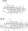
- Figs.4a and 4b illustrate a second example of the present invention, in which an energy storage module 10 comprising a plurality of energy storage devices 20 is shown.
- the module comprises a plurality of electronics boards 34, 36 in contact with exposed areas of tabs 22 of the energy storage devices, but in place of the printed circuit board 24 for the electronics boards, this example uses a flexible printed circuit cable 25 with a ground plane 16 for the electronics boards, i.e. having the same layer construction as illustrated in Fig.6 .
- the use of the more rigid PCBs as illustrated in Fig.3a and 3b is preferred because they are less expensive than flexible PCBs and too much flexibility may make it more difficult to ensure a good connection to the tabs, or otherwise complicate the assembly.
- these electronics boards are then electrically connected together by flexible printed circuit cables 25 between the boards, the FPCs having at least one ground reference plane 16, which provides a low impedance ground plane between the electronics boards 34.
- This embodiment provides boards with mechanical flexibility, as well as the connections between them mechanically flexible, so that the connection can be made between boards in different geometrical planes and with any shape of cells.
- the ground planes of the electronics boards 34, 36 provide the common low impedance connection. Signal wires that are routed through any of the FPCs, whether the electronics board 34, 36, or the connections 25, are protected against noise by the FPC ground plane 16.
- the flexible printed circuit boards may be formed as a multi-layer signal and ground, where each ground plane layer performs as an electrical shield and a low impedance connection to ensure that all signals have the same ground potential.
- the flexible printed circuit board 25 and electronics boards 24, 26 do not form a continuous loop, but may have a gap in the connections at one end.
- the flexible printed circuit board 25 and electronics boards 24, 26 may form a continuous loop, as shown in Figs.3b and 4b .
- Some energy storage devices have been omitted for clarity in Figs.3b and 4b and in practice, the flexible printed circuit board at the end of a stack of energy storage devices may be held in close contact with them.
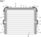
- Fig.7 illustrates part of the energy storage module from above, showing the end to end nature of the ground layer formed by the combination of rigid and flexible printed circuit boards and their ground layers. Details of the electrical contact between the energy storage devices and the electronics boards are omitted for clarity.
- Each flexible printed circuit board 25 is mounted at its ends 30 in contact with the ground layer 13 of each rigid printed circuit board 24 that it joins together.
- the ground layers of the flexible and rigid printed circuit boards together provide electrical grounding at substantially the same potential across all the electronics boards and all the flexible printed circuit boards.
- the PCB assemblies of the energy storage module may have direct contact with the battery tabs, whatever the number of cells, or the location of the tabs on the cells.
- the direct contact of the PCBs with the tabs means that mounting of the energy storage devices within the energy storage module is simpler and cheaper than using wires or other types of connectors between the tabs and the PCBs.
- a battery module that is more robust against noise is particularly useful in industrial applications, where noise levels may be very high.
- electrochemical cells such as batteries, for example Li-ion, alkaline, or NiMh batteries, or others
- the invention applies to other types of stored energy units, in particular non-cylindrical capacitors, ultracapacitors, or supercapacitors, fuel cells, or other types of energy storage which have a surface that can be cooled by a cooler and which may also suffer if the temperature of modules of the stored energy units regularly goes outside a preferred operating range, reducing the overall lifetime and increasing maintenance costs.
Landscapes
- Chemical & Material Sciences (AREA)
- Chemical Kinetics & Catalysis (AREA)
- Electrochemistry (AREA)
- General Chemical & Material Sciences (AREA)
- Engineering & Computer Science (AREA)
- Microelectronics & Electronic Packaging (AREA)
- Manufacturing & Machinery (AREA)
- Battery Mounting, Suspending (AREA)
Claims (7)
- Energiespeicherungsmodul (10), das Folgendes umfasst: mehrere Energiespeicherungsvorrichtungen (20), die elektrisch miteinander in Reihe verbunden sind; und mehrere Elektronikplatinen (24, 26), die über das Modul verteilt sind, in elektrischem Kontakt mit einer oder mehreren der Energiespeicherungsvorrichtungen; wobei das Modul ferner mehrere flexible Leiterplatten (25) umfasst, wodurch jede der mehreren Elektronikplatinen (24) durch eine unterschiedliche der mehreren flexiblen Leiterplatten (25) mit einer benachbarten der mehreren Elektronikplatinen (26) elektrisch in Reihe verbunden ist; und wobei, für jede Elektronikplatine und für jede flexible Leiterplatte, eine Massefläche (13, 16) bereitgestellt ist, wodurch die Masseflächen eine elektrische Masseverbindung auf im Wesentlichen dem gleichen Potential über sämtliche Elektronikplatinen und sämtliche flexiblen Leiterplatten hinweg bereitstellen.
- Modul nach Anspruch 1, wobei die Elektronikplatinen (24, 26) starre Leiterplatten umfassen.
- Modul nach Anspruch 1 oder Anspruch 2, wobei die flexiblen Leiterplatten (25) zwischen jeder Elektronikplatine (24, 26) flexible Leiterplattenkabel umfassen.
- Modul nach einem vorhergehenden Anspruch, wobei das Modul ferner Kommunikationsverbindungen auf den flexiblen Leiterplatten (25) zwischen Elektronikplatinen (24, 26) zum Kommunizieren von Daten, die auf jeder Elektronikplatine gesammelt werden, an eine Steuerung (9) umfasst.
- Modul nach einem vorhergehenden Anspruch, wobei die Massefläche (16) der flexiblen Leiterplatte (25) Folgendes umfasst: wenigstens eine Masseschicht zum Abschirmen von Kommunikationsverbindungen und zum Bereitstellen der Masse für die Elektronikplatine (24, 26) oder zum Erweitern der Masse von jeder Elektronikplatine; und wenigstens eine Signalschicht.
- Modul nach Anspruch 5, wobei die Signalschicht eine einer reinen Signalschicht oder einer gemischten Masse- und Signalschicht umfasst.
- Modul nach einem vorhergehenden Anspruch, wobei die in Reihe verbundenen flexiblen Leiterplatten (25) und Elektronikplatinen (24, 26) eine kontinuierliche Schleife um die Energiespeicherungsmodule (10) herum bilden.
Applications Claiming Priority (2)
| Application Number | Priority Date | Filing Date | Title |
|---|---|---|---|
| GB1808368.3A GB2574013B (en) | 2018-05-22 | 2018-05-22 | Energy storage module |
| PCT/EP2019/063148 WO2019224213A1 (en) | 2018-05-22 | 2019-05-21 | Energy storage module |
Publications (3)
| Publication Number | Publication Date |
|---|---|
| EP3797443A1 EP3797443A1 (de) | 2021-03-31 |
| EP3797443B1 true EP3797443B1 (de) | 2025-04-09 |
| EP3797443C0 EP3797443C0 (de) | 2025-04-09 |
Family
ID=62812557
Family Applications (1)
| Application Number | Title | Priority Date | Filing Date |
|---|---|---|---|
| EP19729624.7A Active EP3797443B1 (de) | 2018-05-22 | 2019-05-21 | Energiespeichermodul |
Country Status (8)
| Country | Link |
|---|---|
| US (1) | US11355790B2 (de) |
| EP (1) | EP3797443B1 (de) |
| KR (1) | KR102808250B1 (de) |
| CN (1) | CN112154551B (de) |
| ES (1) | ES3032857T3 (de) |
| GB (1) | GB2574013B (de) |
| PL (1) | PL3797443T3 (de) |
| WO (1) | WO2019224213A1 (de) |
Families Citing this family (1)
| Publication number | Priority date | Publication date | Assignee | Title |
|---|---|---|---|---|
| CN115621574A (zh) * | 2022-10-25 | 2023-01-17 | 湖北亿纬动力有限公司 | 一种电路板及电池管理系统 |
Family Cites Families (15)
| Publication number | Priority date | Publication date | Assignee | Title |
|---|---|---|---|---|
| JP2010257775A (ja) * | 2009-04-24 | 2010-11-11 | Sanyo Electric Co Ltd | バッテリモジュール、バッテリシステムおよび電動車両 |
| WO2012011237A1 (ja) * | 2010-07-23 | 2012-01-26 | 三洋電機株式会社 | バッテリモジュール、バッテリシステム、電動車両、移動体、電力貯蔵装置および電源装置 |
| CN102544616B (zh) * | 2010-12-08 | 2014-07-30 | 比亚迪股份有限公司 | 一种电池模组 |
| JP2013004185A (ja) * | 2011-06-13 | 2013-01-07 | Auto Network Gijutsu Kenkyusho:Kk | 電池配線モジュール |
| DE102012215748A1 (de) * | 2012-09-05 | 2014-03-06 | Robert Bosch Gmbh | Elektrische Energiespeicherzelle und Verfahren zum Herstellen einer elektrischen Energiespeicherzelle |
| US20140120401A1 (en) * | 2012-10-30 | 2014-05-01 | Samsung Sdi Co., Ltd. | Connecting structure between circuit boards and battery pack having the same |
| JP2014220148A (ja) * | 2013-05-09 | 2014-11-20 | 愛三工業株式会社 | バスバーモジュール |
| TW201507319A (zh) * | 2013-08-05 | 2015-02-16 | Hon Hai Prec Ind Co Ltd | 充放電系統 |
| JP6083371B2 (ja) * | 2013-12-02 | 2017-02-22 | 株式会社デンソー | 組電池 |
| DE102016000843A1 (de) * | 2016-01-27 | 2017-07-27 | Diehl Metal Applications Gmbh | Kontaktierungssystem für Energiespeicherzellen und Energiespeicher |
| JP6692188B2 (ja) * | 2016-03-09 | 2020-05-13 | 株式会社東芝 | 電池、蓄電池、及び電気装置 |
| JP6533500B2 (ja) * | 2016-08-12 | 2019-06-19 | 矢崎総業株式会社 | バスバモジュール及び電池パック |
| JP6763729B2 (ja) * | 2016-09-26 | 2020-09-30 | 矢崎総業株式会社 | 電池状態検出装置 |
| JP6227082B1 (ja) * | 2016-10-03 | 2017-11-08 | 株式会社オートネットワーク技術研究所 | 接続モジュール |
| WO2018124494A2 (ko) * | 2016-12-27 | 2018-07-05 | 주식회사 유라코퍼레이션 | 버스바 어셈블리 및 프레임 조립체 |
-
2018
- 2018-05-22 GB GB1808368.3A patent/GB2574013B/en active Active
-
2019
- 2019-05-21 PL PL19729624.7T patent/PL3797443T3/pl unknown
- 2019-05-21 KR KR1020207033341A patent/KR102808250B1/ko active Active
- 2019-05-21 US US17/049,229 patent/US11355790B2/en active Active
- 2019-05-21 CN CN201980034198.6A patent/CN112154551B/zh active Active
- 2019-05-21 WO PCT/EP2019/063148 patent/WO2019224213A1/en not_active Ceased
- 2019-05-21 ES ES19729624T patent/ES3032857T3/es active Active
- 2019-05-21 EP EP19729624.7A patent/EP3797443B1/de active Active
Also Published As
| Publication number | Publication date |
|---|---|
| GB201808368D0 (en) | 2018-07-11 |
| EP3797443A1 (de) | 2021-03-31 |
| US11355790B2 (en) | 2022-06-07 |
| WO2019224213A1 (en) | 2019-11-28 |
| PL3797443T3 (pl) | 2025-07-28 |
| KR102808250B1 (ko) | 2025-05-14 |
| EP3797443C0 (de) | 2025-04-09 |
| GB2574013B (en) | 2021-04-07 |
| CA3098515A1 (en) | 2019-11-28 |
| US20210367276A1 (en) | 2021-11-25 |
| CN112154551A (zh) | 2020-12-29 |
| GB2574013A (en) | 2019-11-27 |
| CN112154551B (zh) | 2023-04-28 |
| ES3032857T3 (en) | 2025-07-28 |
| KR20210011929A (ko) | 2021-02-02 |
Similar Documents
| Publication | Publication Date | Title |
|---|---|---|
| CN108780860B (zh) | 用于车辆的电池组和包括电池组的车辆 | |
| CA3054014C (en) | Power supply system | |
| CA3054390C (en) | Power supply system | |
| CN112117412A (zh) | 一种电动汽车动力电池组 | |
| WO2019233896A1 (en) | Energy storage unit | |
| EP3797443B1 (de) | Energiespeichermodul | |
| CN217848195U (zh) | 电池包和动力装置 | |
| CA3098515C (en) | Energy storage module | |
| EP3804004B1 (de) | Befestigungssystem für ein energiespeichermodul | |
| CN218343271U (zh) | 电池包的电气集成模块、电池包和动力装置 | |
| CN217656026U (zh) | 电池包和动力装置 | |
| EP4425644A1 (de) | Energiespeichervorrichtung für ein stromversorgungssystem | |
| CN223584406U (zh) | 一种ccs集成结构及ups电池 | |
| CA3099416C (en) | Mounting system | |
| CN217239579U (zh) | 动力电池包和动力装置 | |
| JP2024157457A (ja) | 電池の冷却装置 | |
| CN111130167A (zh) | 氢燃料电池的电压转换设备 |
Legal Events
| Date | Code | Title | Description |
|---|---|---|---|
| STAA | Information on the status of an ep patent application or granted ep patent |
Free format text: STATUS: UNKNOWN |
|
| STAA | Information on the status of an ep patent application or granted ep patent |
Free format text: STATUS: THE INTERNATIONAL PUBLICATION HAS BEEN MADE |
|
| PUAI | Public reference made under article 153(3) epc to a published international application that has entered the european phase |
Free format text: ORIGINAL CODE: 0009012 |
|
| STAA | Information on the status of an ep patent application or granted ep patent |
Free format text: STATUS: REQUEST FOR EXAMINATION WAS MADE |
|
| 17P | Request for examination filed |
Effective date: 20201016 |
|
| AK | Designated contracting states |
Kind code of ref document: A1 Designated state(s): AL AT BE BG CH CY CZ DE DK EE ES FI FR GB GR HR HU IE IS IT LI LT LU LV MC MK MT NL NO PL PT RO RS SE SI SK SM TR |
|
| AX | Request for extension of the european patent |
Extension state: BA ME |
|
| DAV | Request for validation of the european patent (deleted) | ||
| DAX | Request for extension of the european patent (deleted) | ||
| RAP1 | Party data changed (applicant data changed or rights of an application transferred) |
Owner name: SIEMENS ENERGY AS |
|
| REG | Reference to a national code |
Ref legal event code: R079 Ipc: H01M0010420000 Ref country code: DE Ref legal event code: R079 Ref document number: 602019068392 Country of ref document: DE Free format text: PREVIOUS MAIN CLASS: H01M0002100000 Ipc: H01M0010420000 |
|
| GRAP | Despatch of communication of intention to grant a patent |
Free format text: ORIGINAL CODE: EPIDOSNIGR1 |
|
| STAA | Information on the status of an ep patent application or granted ep patent |
Free format text: STATUS: GRANT OF PATENT IS INTENDED |
|
| RIC1 | Information provided on ipc code assigned before grant |
Ipc: H01M 10/42 20060101AFI20241115BHEP |
|
| INTG | Intention to grant announced |
Effective date: 20241129 |
|
| GRAS | Grant fee paid |
Free format text: ORIGINAL CODE: EPIDOSNIGR3 |
|
| GRAA | (expected) grant |
Free format text: ORIGINAL CODE: 0009210 |
|
| STAA | Information on the status of an ep patent application or granted ep patent |
Free format text: STATUS: THE PATENT HAS BEEN GRANTED |
|
| AK | Designated contracting states |
Kind code of ref document: B1 Designated state(s): AL AT BE BG CH CY CZ DE DK EE ES FI FR GB GR HR HU IE IS IT LI LT LU LV MC MK MT NL NO PL PT RO RS SE SI SK SM TR |
|
| REG | Reference to a national code |
Ref country code: GB Ref legal event code: FG4D |
|
| REG | Reference to a national code |
Ref country code: CH Ref legal event code: EP |
|
| REG | Reference to a national code |
Ref country code: IE Ref legal event code: FG4D |
|
| U01 | Request for unitary effect filed |
Effective date: 20250409 |
|
| U07 | Unitary effect registered |
Designated state(s): AT BE BG DE DK EE FI FR IT LT LU LV MT NL PT RO SE SI Effective date: 20250415 |
|
| U20 | Renewal fee for the european patent with unitary effect paid |
Year of fee payment: 7 Effective date: 20250526 |
|
| PGFP | Annual fee paid to national office [announced via postgrant information from national office to epo] |
Ref country code: ES Payment date: 20250611 Year of fee payment: 7 |
|
| PGFP | Annual fee paid to national office [announced via postgrant information from national office to epo] |
Ref country code: NO Payment date: 20250520 Year of fee payment: 7 |
|
| PGFP | Annual fee paid to national office [announced via postgrant information from national office to epo] |
Ref country code: GR Payment date: 20250625 Year of fee payment: 7 |
|
| PGFP | Annual fee paid to national office [announced via postgrant information from national office to epo] |
Ref country code: TR Payment date: 20250527 Year of fee payment: 7 |
|
| REG | Reference to a national code |
Ref country code: ES Ref legal event code: FG2A Ref document number: 3032857 Country of ref document: ES Kind code of ref document: T3 Effective date: 20250728 |
|
| REG | Reference to a national code |
Ref country code: GR Ref legal event code: EP Ref document number: 20250401167 Country of ref document: GR Effective date: 20250707 |
|
| PGFP | Annual fee paid to national office [announced via postgrant information from national office to epo] |
Ref country code: PL Payment date: 20250513 Year of fee payment: 7 |
|
| PG25 | Lapsed in a contracting state [announced via postgrant information from national office to epo] |
Ref country code: HR Free format text: LAPSE BECAUSE OF FAILURE TO SUBMIT A TRANSLATION OF THE DESCRIPTION OR TO PAY THE FEE WITHIN THE PRESCRIBED TIME-LIMIT Effective date: 20250409 |
|
| PG25 | Lapsed in a contracting state [announced via postgrant information from national office to epo] |
Ref country code: RS Free format text: LAPSE BECAUSE OF FAILURE TO SUBMIT A TRANSLATION OF THE DESCRIPTION OR TO PAY THE FEE WITHIN THE PRESCRIBED TIME-LIMIT Effective date: 20250709 |
|
| PG25 | Lapsed in a contracting state [announced via postgrant information from national office to epo] |
Ref country code: IS Free format text: LAPSE BECAUSE OF FAILURE TO SUBMIT A TRANSLATION OF THE DESCRIPTION OR TO PAY THE FEE WITHIN THE PRESCRIBED TIME-LIMIT Effective date: 20250809 |
|
| REG | Reference to a national code |
Ref country code: CH Ref legal event code: H13 Free format text: ST27 STATUS EVENT CODE: U-0-0-H10-H13 (AS PROVIDED BY THE NATIONAL OFFICE) Effective date: 20251223 |
|
| PG25 | Lapsed in a contracting state [announced via postgrant information from national office to epo] |
Ref country code: SM Free format text: LAPSE BECAUSE OF FAILURE TO SUBMIT A TRANSLATION OF THE DESCRIPTION OR TO PAY THE FEE WITHIN THE PRESCRIBED TIME-LIMIT Effective date: 20250409 |
|
| REG | Reference to a national code |
Ref country code: CH Ref legal event code: W10 Free format text: ST27 STATUS EVENT CODE: U-0-0-W10-W00 (AS PROVIDED BY THE NATIONAL OFFICE) Effective date: 20260114 |
|
| PG25 | Lapsed in a contracting state [announced via postgrant information from national office to epo] |
Ref country code: CH Free format text: LAPSE BECAUSE OF NON-PAYMENT OF DUE FEES Effective date: 20250531 |
|
| PG25 | Lapsed in a contracting state [announced via postgrant information from national office to epo] |
Ref country code: CZ Free format text: LAPSE BECAUSE OF FAILURE TO SUBMIT A TRANSLATION OF THE DESCRIPTION OR TO PAY THE FEE WITHIN THE PRESCRIBED TIME-LIMIT Effective date: 20250409 |
|
| PGFP | Annual fee paid to national office [announced via postgrant information from national office to epo] |
Ref country code: CY Payment date: 20250428 Year of fee payment: 7 |
|
| PG25 | Lapsed in a contracting state [announced via postgrant information from national office to epo] |
Ref country code: SK Free format text: LAPSE BECAUSE OF FAILURE TO SUBMIT A TRANSLATION OF THE DESCRIPTION OR TO PAY THE FEE WITHIN THE PRESCRIBED TIME-LIMIT Effective date: 20250409 |
|
| PG25 | Lapsed in a contracting state [announced via postgrant information from national office to epo] |
Ref country code: MC Free format text: LAPSE BECAUSE OF FAILURE TO SUBMIT A TRANSLATION OF THE DESCRIPTION OR TO PAY THE FEE WITHIN THE PRESCRIBED TIME-LIMIT Effective date: 20250409 |
|
| RAP2 | Party data changed (patent owner data changed or rights of a patent transferred) |
Owner name: SIEMENS ENERGY GLOBAL GMBH & CO. KG |
|
| U1K | Transfer of rights of the unitary patent after the registration of the unitary effect |
Owner name: SIEMENS ENERGY GLOBAL GMBH & CO. KG; DE |
|
| PLBE | No opposition filed within time limit |
Free format text: ORIGINAL CODE: 0009261 |
|
| STAA | Information on the status of an ep patent application or granted ep patent |
Free format text: STATUS: NO OPPOSITION FILED WITHIN TIME LIMIT |
|
| REG | Reference to a national code |
Ref country code: CH Ref legal event code: L10 Free format text: ST27 STATUS EVENT CODE: U-0-0-L10-L00 (AS PROVIDED BY THE NATIONAL OFFICE) Effective date: 20260218 |
|
| REG | Reference to a national code |
Ref country code: GB Ref legal event code: 732E Free format text: REGISTERED BETWEEN 20260129 AND 20260204 |
|
| 26N | No opposition filed |
Effective date: 20260112 |
|
| PGFP | Annual fee paid to national office [announced via postgrant information from national office to epo] |
Ref country code: GB Payment date: 20260323 Year of fee payment: 8 |
|
| PG25 | Lapsed in a contracting state [announced via postgrant information from national office to epo] |
Ref country code: IE Free format text: LAPSE BECAUSE OF NON-PAYMENT OF DUE FEES Effective date: 20250521 |