EP3797202B1 - Échelle anti-chute - Google Patents
Échelle anti-chute Download PDFInfo
- Publication number
- EP3797202B1 EP3797202B1 EP19807307.4A EP19807307A EP3797202B1 EP 3797202 B1 EP3797202 B1 EP 3797202B1 EP 19807307 A EP19807307 A EP 19807307A EP 3797202 B1 EP3797202 B1 EP 3797202B1
- Authority
- EP
- European Patent Office
- Prior art keywords
- ladder
- cord
- cable
- tensioner
- user
- Prior art date
- Legal status (The legal status is an assumption and is not a legal conclusion. Google has not performed a legal analysis and makes no representation as to the accuracy of the status listed.)
- Active
Links
- 230000008878 coupling Effects 0.000 claims description 25
- 238000010168 coupling process Methods 0.000 claims description 25
- 238000005859 coupling reaction Methods 0.000 claims description 25
- 238000000034 method Methods 0.000 description 6
- 210000003813 thumb Anatomy 0.000 description 5
- 239000000463 material Substances 0.000 description 4
- 230000007246 mechanism Effects 0.000 description 4
- 230000002093 peripheral effect Effects 0.000 description 4
- 208000027418 Wounds and injury Diseases 0.000 description 3
- 230000008901 benefit Effects 0.000 description 3
- 238000007689 inspection Methods 0.000 description 3
- 238000012360 testing method Methods 0.000 description 3
- 230000004913 activation Effects 0.000 description 2
- 230000001174 ascending effect Effects 0.000 description 2
- 238000006243 chemical reaction Methods 0.000 description 2
- 230000006378 damage Effects 0.000 description 2
- 210000004247 hand Anatomy 0.000 description 2
- 239000000758 substrate Substances 0.000 description 2
- 208000003443 Unconsciousness Diseases 0.000 description 1
- 230000009471 action Effects 0.000 description 1
- 238000004873 anchoring Methods 0.000 description 1
- 230000003466 anti-cipated effect Effects 0.000 description 1
- 238000009937 brining Methods 0.000 description 1
- 230000009194 climbing Effects 0.000 description 1
- 238000013461 design Methods 0.000 description 1
- 238000010586 diagram Methods 0.000 description 1
- 230000006872 improvement Effects 0.000 description 1
- 208000014674 injury Diseases 0.000 description 1
- 238000012423 maintenance Methods 0.000 description 1
- 239000002184 metal Substances 0.000 description 1
- 238000012986 modification Methods 0.000 description 1
- 230000004048 modification Effects 0.000 description 1
- 230000008439 repair process Effects 0.000 description 1
- 230000000284 resting effect Effects 0.000 description 1
- 230000000717 retained effect Effects 0.000 description 1
- 230000002441 reversible effect Effects 0.000 description 1
- 238000000926 separation method Methods 0.000 description 1
- 230000035939 shock Effects 0.000 description 1
- 230000003019 stabilising effect Effects 0.000 description 1
- 238000004804 winding Methods 0.000 description 1
Images


Classifications
-
- E—FIXED CONSTRUCTIONS
- E06—DOORS, WINDOWS, SHUTTERS, OR ROLLER BLINDS IN GENERAL; LADDERS
- E06C—LADDERS
- E06C1/00—Ladders in general
- E06C1/02—Ladders in general with rigid longitudinal member or members
- E06C1/04—Ladders for resting against objects, e.g. walls poles, trees
- E06C1/08—Ladders for resting against objects, e.g. walls poles, trees multi-part
- E06C1/12—Ladders for resting against objects, e.g. walls poles, trees multi-part extensible, e.g. telescopic
-
- E—FIXED CONSTRUCTIONS
- E06—DOORS, WINDOWS, SHUTTERS, OR ROLLER BLINDS IN GENERAL; LADDERS
- E06C—LADDERS
- E06C7/00—Component parts, supporting parts, or accessories
- E06C7/18—Devices for preventing persons from falling
- E06C7/186—Rail or rope for guiding a safety attachment, e.g. a fall arrest system
-
- A—HUMAN NECESSITIES
- A62—LIFE-SAVING; FIRE-FIGHTING
- A62B—DEVICES, APPARATUS OR METHODS FOR LIFE-SAVING
- A62B1/00—Devices for lowering persons from buildings or the like
- A62B1/06—Devices for lowering persons from buildings or the like by making use of rope-lowering devices
-
- E—FIXED CONSTRUCTIONS
- E06—DOORS, WINDOWS, SHUTTERS, OR ROLLER BLINDS IN GENERAL; LADDERS
- E06C—LADDERS
- E06C5/00—Ladders characterised by being mounted on undercarriages or vehicles Securing ladders on vehicles
- E06C5/32—Accessories, e.g. brakes on ladders
- E06C5/36—Safety devices against slipping or falling of ladders; Safety devices against overloading ladders
-
- E—FIXED CONSTRUCTIONS
- E06—DOORS, WINDOWS, SHUTTERS, OR ROLLER BLINDS IN GENERAL; LADDERS
- E06C—LADDERS
- E06C7/00—Component parts, supporting parts, or accessories
- E06C7/14—Holders for pails or other equipment on or for ladders
-
- E—FIXED CONSTRUCTIONS
- E06—DOORS, WINDOWS, SHUTTERS, OR ROLLER BLINDS IN GENERAL; LADDERS
- E06C—LADDERS
- E06C7/00—Component parts, supporting parts, or accessories
- E06C7/18—Devices for preventing persons from falling
- E06C7/188—Accessories for temporary stabilising a ladder, e.g. temporary attaching devices
-
- E—FIXED CONSTRUCTIONS
- E06—DOORS, WINDOWS, SHUTTERS, OR ROLLER BLINDS IN GENERAL; LADDERS
- E06C—LADDERS
- E06C7/00—Component parts, supporting parts, or accessories
- E06C7/42—Ladder feet; Supports therefor
- E06C7/423—Ladder stabilising struts
-
- E—FIXED CONSTRUCTIONS
- E06—DOORS, WINDOWS, SHUTTERS, OR ROLLER BLINDS IN GENERAL; LADDERS
- E06C—LADDERS
- E06C7/00—Component parts, supporting parts, or accessories
- E06C7/42—Ladder feet; Supports therefor
- E06C7/44—Means for mounting ladders on uneven ground
-
- F—MECHANICAL ENGINEERING; LIGHTING; HEATING; WEAPONS; BLASTING
- F16—ENGINEERING ELEMENTS AND UNITS; GENERAL MEASURES FOR PRODUCING AND MAINTAINING EFFECTIVE FUNCTIONING OF MACHINES OR INSTALLATIONS; THERMAL INSULATION IN GENERAL
- F16D—COUPLINGS FOR TRANSMITTING ROTATION; CLUTCHES; BRAKES
- F16D63/00—Brakes not otherwise provided for; Brakes combining more than one of the types of groups F16D49/00 - F16D61/00
- F16D63/008—Brakes acting on a linearly moving member
-
- E—FIXED CONSTRUCTIONS
- E04—BUILDING
- E04G—SCAFFOLDING; FORMS; SHUTTERING; BUILDING IMPLEMENTS OR AIDS, OR THEIR USE; HANDLING BUILDING MATERIALS ON THE SITE; REPAIRING, BREAKING-UP OR OTHER WORK ON EXISTING BUILDINGS
- E04G21/00—Preparing, conveying, or working-up building materials or building elements in situ; Other devices or measures for constructional work
- E04G21/32—Safety or protective measures for persons during the construction of buildings
- E04G21/3204—Safety or protective measures for persons during the construction of buildings against falling down
-
- E—FIXED CONSTRUCTIONS
- E04—BUILDING
- E04G—SCAFFOLDING; FORMS; SHUTTERING; BUILDING IMPLEMENTS OR AIDS, OR THEIR USE; HANDLING BUILDING MATERIALS ON THE SITE; REPAIRING, BREAKING-UP OR OTHER WORK ON EXISTING BUILDINGS
- E04G5/00—Component parts or accessories for scaffolds
- E04G5/003—Devices for storing material on the scaffold
-
- E—FIXED CONSTRUCTIONS
- E06—DOORS, WINDOWS, SHUTTERS, OR ROLLER BLINDS IN GENERAL; LADDERS
- E06C—LADDERS
- E06C7/00—Component parts, supporting parts, or accessories
- E06C7/42—Ladder feet; Supports therefor
- E06C7/46—Non-skid equipment
Definitions
- the invention relates to a ladder comprising a fall control system.
- the separation of the user from the ladder can be brought about by user error, or by a lack of stability in the ladder causing an unwanted movement of the ladder footing.
- To rescue the incapacitated user then requires third-party assistance, whether in the form of emergency services or a work colleague. Frequently, this will expose the third-party rescuer to a similarly elevated, and dangerous location, to retrieve the user and sever any fixed tethers that the user has engaged prior to their accident.
- the invention provides a ladder having a fall control system, according to claim 1, comprising: a ladder; a tensioner mounted towards a bottom end of the ladder; a mount mounted towards a top end of the ladder; a cable that extends from the tensioner and over the mount in a looped configuration; and an arrestor movably engaged with the cable for coupling a user to the cable, wherein the tensioner has a locked configuration for holding tension on the cable to support a weight of the user and an open configuration for allowing the cable to pass through the tensioner.
- the ladder may be an extendable ladder.
- the cable may have a fixed end secured to the tensioner and a free end that passes through the tensioner to vary the length of cable in the fall control system.
- the cable may be a rope.
- the rope may have a termination end configured to be removably coupled with the tensioner.
- the mount may comprise a closable opening for receiving and retaining the cable therein.
- the mount may comprise a cable guide turning the cable through about 180 degrees. This allows the mount to guide the cable as it passes over the mount and to smoothly feed the cable over the mount.
- the cable may comprise a position indicator for marking the attachment point for the arrestor. This reduces the risk of a user connecting the arrestor to the wrong portion of the cable.
- the arrestor may be couplable with a safety harness for securing the user therein.
- the ladder may additionally comprise an intermediary mount for guiding the cable along a longitudinal axis of the ladder.
- the arrestor may comprise a connector for selectively engaging the intermediary mount. This allows the user to support themselves laterally while working on the ladder. This may also allow the user to have two free hands, utilising the intermediary mount as a centre balance.
- the arrestor may have an active configuration where the arrestor locks on the cable and thereby holds the user at a fixed point on the cable.
- the arrestor may have an inactive configuration where the arrestor can slide freely along the cable.
- the ladder may further comprise a pair of adjustable legs for varying a width of a base of the ladder.
- the ladder may further comprise a tether system for tethering the ladder to an anchor point.
- the ladder may further comprise a cable store for storing the unused cable.
- the cable store may be releasably engaged with the ladder.
- the tensioner may be configured to engage a centre portion of the cable, the centre potion located between the free ends of the cable.
- the tensioner may be configured to thread a mid-section of the cable between an inlet and an outlet thereof.
- the tensioner is rigidly mounted to the ladder at a height accessible from the ground on which the ladder is supported.
- the cable may be confined to a front face of the ladder.
- the cable may be separable from the ladder for ease of inspection and replacement.
- the invention provides a ladder having a tether system for tethering to an anchor, comprising: a ladder; a brake mounted towards an upper end of the ladder; a coupling mounted towards a bottom end of the ladder; and a cord extending from the coupling to the brake via the anchor point, wherein the brake has an operative configuration for holding tension on the cord against the anchor and an inoperative configuration allowing the cord to pass through the brake.
- the brake in the operative configuration may tension the cord against the anchor, such that a horizontal force is applied by the cord pulling the ladder toward the anchor and a vertical force is applied pulling the ladder toward the ground on which the ladder is supported.
- the coupling may comprise a bracket for securing an end portion of the cord thereto.
- the coupling may further comprise a hook for stowing the cord on the ladder, when the tether system is not in use.
- the brake may have an inlet for receiving the cord and an outlet by which a free end of the cord exits the brake. A force applied to the free end of the cord may tension the cord against the anchor, and in use, the tension on the cord is maintained by the brake.
- the brake may comprise an actuator for selecting the operative configuration and the inoperative configuration of the brake.
- the brake may comprise internal projections for gripping the cord.
- the brake may comprise a locking member, configured to bias the brake to the operative configuration.
- the brake may be rigidly mounted to the ladder.
- the cord may be separable from the ladder for ease of inspection and replacement.
- a tensioner for controlling tension on a cable, having a default locked configuration and an open configuration, comprising: a body having an inlet and an outlet interconnected by an internal channel that extends through the body for receiving the cable; the internal channel being defined by a wall and a rotatable locking member, wherein, in use, tension on the cable in a first direction applies a force to the rotatable locking member that urges the locking member into the channel and impedes movement of the cable through the channel thereby placing the tensioner in the default locked configuration, and wherein, in use, tension on the cable in a second, opposing direction applies a force to the rotatable locking member that urges the locking member out of the channel to place the tensioner in the open configuration.
- movement of the cord in a second, opposing direction may relieve the force on the locking member clearing the channel and thereby allowing movement of the cable through the channel.
- the tensioner provides a locked configuration where the cable cannot move within the channel and an open configuration where the cable can move within the channel.
- the locked configuration may allow movement of the cable in the first direction and prohibit movement of the cable in the second direction.
- the tensioner may further comprise a release for selectively engaging the open configuration of the tensioner.
- the tensioner may further comprise a lock disabling the release.
- the tensioner may further comprise a cover having a slot, the cover being rotatably mounted to the body such that the slot can be selectively aligned with each of the inlet and the outlet to insert or removed the cable from the internal channel.
- the cover may be coaxially mounted to the body sharing a common central axis of rotation.
- the internal channel may receive a mid-portion of the cable with the cover rotatably engaged with the body.
- the channel may be ox bow shaped.
- the locking member may comprise a pulley or a sheave for guiding the cable thereabout, a protrusion for extending into the channel to engage with the cable and a shoulder for engagement with the release.
- the release may be pivotally mounted in a side wall of the body and pivot outwardly for activation.
- the release may be biased to maintain the tensioner in the locked configuration.
- the release may comprise a protruding lip, that on rotation is brought into engagement with the shoulder of the locking member, rotating the locking member such that the protrusion is drawn out of the channel and out of contact with the cable.
- the protrusion may comprise a recess for engaging the cable.
- the recess may be V-shaped.
- the recess may be a notch.
- the recess may have ridges to increase friction when in contact with the cable.
- the recess may be toothed to grip the cable on contact therewith.
- the wall of the channel may be configured to provide a bulge that narrows the channel.
- the bulge may be located in the channel adjacent the protrusion of the locking member to define a pinch point on the cable.
- the wall of the channel may be a side wall of the body.
- the wall may be a stationary wall.
- hook is understood herein to refer to fixed hooks and specialised closable hooks, such as carabiners having an openable or spring loaded or screw-locked gate for forming reversible couplings.
- a ladder having a fall control system 100 comprising: a ladder 1; a tensioner 20 mounted towards a bottom end 3 of the ladder 1; a mount 9 located towards a top end 4 of the ladder 1; a cable illustrated as a rope, or cord 10 that extends from the tensioner 20 and over the mount 9 in a looped configuration; and an arrestor 15 movably engaged with the cord 10 for coupling a user U to the cord 10, wherein the tensioner 20 has a locked configuration for holding tension on the cord 10 to support a weight of the user U and an open configuration for allowing the cord 10 to pass through the tensioner 20.
- the tensioner is illustrated in the following Figures as a descender 20.
- the descender 20 is rigidly fixed to the ladder and does not move with the movement of the user U.
- the descender 20 may be detachable from the ladder to facilitate maintenance or replacement.
- the ladder 1 of Figure 1A is an extendable ladder having a base portion 1a and a fly portion 1b. Although not illustrated, additional moveable, fly portions can be added to the ladder 1 to increase the available extension. Accordingly, the cable, illustrated as cord 10 of the fall control ladder 100 is configured to adjust as the ladder 1 is extended during use. It is also contemplated that the cord 10 could be adapted to a non-extending ladder 1 of fixed height, where the cable forms a closed loop or winch 5 routed through the descender 20 and up and around the upper mount 9 using and a looped cord 10 of fixed length.
- the cord 10 may be a closed loop that runs through the descender 20 and over the second mount 9.
- the user will connect to the cord 10 via an arrestor 15 and can only travel to the upper end 3 of the ladder 1. If the user becomes incapacitated, a third-party operator can use the descender 20 in the manner described herein to lower the user on the cord 10, via the arrestor 15 back towards the lower end 3 of the ladder 1 and the ground G upon which it is resting.
- the cord 10 described herein is looped between the descender 20 and the second mount 9 with a free end 10c, to allow the cord 10 to extend as the extendable ladder 1 increases in length.
- the selected cord 10 must provide sufficient length of cord 10 for twice the maximum height of the ladder (at full extension) and a further length of the ladder (at full extension) being the surplus cord 10 required to descend an incapacitated used back to the ground G on which the fall control ladder 100 is supported.
- the unused cord 10 is stored in a cord bag 11.
- the bag 11 is open ended and allows the cord 10 to be smoothly drawn from the bag 11 as the ladder 1 is extended.
- the cord 10 can be stored entirely in the bag 11 to prevent the cord 10 from being lost or damaged.
- the bag 11 can be coupled to the ladder 1 and stowed between subsequent the rungs 6 for ease transport. This ensures that the bag 11 and contained cord 10 travel with the fall control ladder 100. Once the ladder 1 is in location, the bag 11 can be unclipped and released from the ladder 1 for ease of use.
- the cord 10 being separable from the fall control ladder 100 provide that the cord 10 can be easily changed or replaced. Moreover, the cord 10 can be checked as frequently as required to ensure that the cord 10 has not been frayed or damaged and still maintains the desired load rating.
- the bag 11 also affords protection for the cord 10 when not in use. Where cords 10 are permanently attached to a ladder 1, it is awkward to remove the cord for inspection and replacement, often leading to cords 10 falling into a poor state of repair, particularly where a ladder 1 is left outdoors in wet conditions or extreme sunlight.
- the descender 20 is positioned at the lower, first end 3 of the ladder 1 to provide access to a user U and an operator O from the ground G (the substrate upon which the ladder 1 is supported).
- the descender 20 provides a controllable braking mechanism permanently affixed to a first rung 6 of the ladder 1.
- the ladder 1 of Figure 1A further comprises a pair of movable, levelling legs 8 for additional stability of the ladder 1, and rubberised feet 8a.
- Levelling legs 8 provide a base of support of approx. 1.3m or 1.6m for ladders beyond 6.4m extended length.
- the legs 8 provide sufficient stability for a fall event of a user over the side of the ladder to remain upright during and after the fall event.
- New international standards require extra stability for all ladders, such as EN131-2 2017 and AS NZS 1892.1 2018.
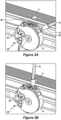
- Figure 1C illustrated a second, upper end 4 of the ladder 1 and a second, upper mounting point 9 for the winch 5.
- the upper mounting point 9 is a smooth arc-sheave about which the cord 10, or life-line rope is partially wound, that acts as an upper guide for the winch 5.
- the upper mount 9 allows the cord 10 to run freely thereabout, extending the winch 10 simultaneously with the ladder 1.
- the upper mount 9 is closable, to ensure that the cord 10 can be wound about the sheave and then captured to prevent the cord from slipping off or away from the upper mount 9.
- FIG. 1C Also illustrated in Figure 1C is an intermediary mount 13.
- the intermediary mount 13 provides a closed eyelet that a user can lock into, when the user reaches the desired working height on the ladder 1.
- a work positioning hook 18 can be attached to the intermediary mount 13 without hampering the movement of the arrestor 15 and cord 10. Once the work positioning hook 18 is engaged with the intermediary mount 13, the user is limited in their reach away from the centre of the ladder 1 preventing overstretching and potential overbalancing of the fall control ladder 100.
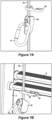
- the work positioning hook 18 will be described in more detail in relation to Figure 7 .
- the work positioning hook 18 is configured as a figure-8, having each of the looped ends of the figure-8 being open to allow the looped end to be easily engaged and disengaged with the cord 10 with a twisting motion of the work positioning hook 18.
- Figure 1B illustrates an arrestor 15 (also referred to as a rope grab) that can travel along the cord 10 and provide the ability to selectively lock to the cord 10 at any given location on the cord 10.
- the arrestor 15 provides a connection point between the user U and the cord 10.
- the user will wear a body harness 14 and use a hook or carabiner 17 on the harness to securely engage with the arrestor 15.
- Figure 1D is a schematic illustration of the fall control ladder 100, illustrating the connections between the cord, the ladder 1, the harness 14, the arrestor 15 and the descender 20.
- the winch is not formed of a closed loop in this embodiment. Instead a termination end 12 of the cord 10 is fixedly mounted to the descender 20.
- the termination end 12 can be formed or metal coated to provide a reliable and engageable connection to the descender 20 (illustrated in Figures 2A-2C ).
- the cord 10 is extended upwardly along the ladder 1 and received and secured into the second mount 9. This length of the cord 10 extending upwardly from the descender 20 to the second, upper mount 9 is length 10a.
- the cord 10 further extends from the upper mount 9 back along the ladder 1 to the descender 20, this length of the cord 10 is length 10b.
- the arrestor 15 is attached to length 10a of the cord 10.
- the user engages their body harness 14 (partially illustrated in Figure 7C ) to the arrestor 15 as they ascend the ladder.
- the arrestor 15 grabs the cord 10 and retains the user's location on the cord 10.
- the operator O can release the cord in a controlled manner through the descender 20, to bring the user via the arrestor 15 back towards the ground G.
- the users weight is acting on the cord 10 to bring the user downwards, while the operator O uses the descender 20 to control the rate of descent.
- the tether system comprises a first coupling 24 located towards a first end of the ladder 3; a brake 25 located towards a second opposing end 4 of the ladder 1; and a tether cord 23 fixed to the first coupling 24, and extending to the brake 25 via a tether point 27, wherein the brake 25 allows movement of the tether cord 23 in a single direction only, such that the tether cord 23 can be tensioned against the tether point 27, to apply a horizontal force F H pulling the ladder 1 toward the tether point 27 and a vertical force Fvthat pulls the ladder 1 toward the ground G (or alternative support surface).
- the ladder 1 is rated between 150-160Kg depending on the exact build specification of the ladder 1.
- ladder 1 is modified to become a fall control ladder 100 the overall system rating is reduced to about 120 Kg due to the load rating on the descender 20.
- the fall control ladder 100 is always used in conjunction with the tether cord 23 as described herein.
- An additional top lash mounting can also be used, when the fall control ladder 100 is being supported against a pole or pole-like structure.
- Using a set of levelling legs 8 on the fall control ladder 100 further provides a stability to the base 3 of the ladder 1 to improve the overall safety of the fall control ladder.
- the work positioning hook 18 provides a still further safety feature to prevent a user from overreaching and overbalancing the fall control ladder 100.
- Figure 1C illustrates the intermediary mount 13 on a rung below the second, upper mount 9, it is contemplated that the fall control ladder 100 will have intermediary mounts 13 located on a front side of the ladder (user facing side) below each rung 6, to provide cooperative mountings for the work positioning hook 18 are a plurality of spaced intervals along the stiles 2. The user is intended to attach the work positioning hook 18 to the nearest rung 6 above their location, to constrain the cord 10.
- the cord 10 is removed from the bag 11 and connected to the descender 20.
- the descender 20 is permanently fixed to the fall control ladder 100.
- the descender has a cylindrical body 21 having a peripheral outer wall 22, and a disc-like cover 26 (see Figure 2A ).
- the peripheral surface 21 provides a keyed-hole 30 for receiving the termination end 12 of the cord 10.
- the termination end 12 is inserted into the keyed-hole 30 at about 2'o'clock (if looking straight at the descender 20) as illustrated in Figure 2B .
- the termination end 12 is rotated anti-clockwise, towards 12'o'clock (brining the cord 10 into alignment with a longitudinal axis of the fall control ladder 100). In this aligned position the termination end 12 cannot be released from the descender 20 and effectively anchors the cord 10 to the descender 20, illustrated in Figure 2C .
- a spring and ball detent (not illustrated) can be incorporated into the keyed-hole 30 to provide resistance to the termination end 12 sliding out of position.
- This spring is contemplated to be simple leaf spring or coil spring, or wave spring in final design. The spring will be easy to overcome by hand force but sufficient to prevent the termination end 12 coming lose or falling out when tension is removed from the cord 10.
- the termination end 12 of the cord 10 is inserted into the keyed-hole 30 of the descender 20 and rotated into alignment with the longitudinal axis of the ladder 1.
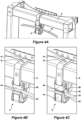
- the upper mount 9 comprises a hanger 37 that is suspended from an upper run 6 of the ladder 1.
- the hanger 37 can be secured to the rung 6 with a fastener 41 such as a bolt, pin, rivet or the like.
- the rung 6 to which the hanger 37 is engaged will be reinforced and therefore, stronger than the lower rungs 6 of the fall control ladder 100.
- the hanger 37 will support between 400kg-500kg load from cord 10a (the side of the cord 10 to which the arrestor 15 and user are attached).
- the hanger 37 will support between 250kg-350kg load from cord 10b on the other side of the sheave 43. This places the working loads on the hanger 37 between 650kg-850kg, where the fixed sheave friction helps reduce total loads on the hanger 37 and therefore through the fall control ladder 100.
- the cord 10 is designed for about 12kN in line with many international fall protection standards.
- the hanger 37 comprises an open hook 42 for receiving the cord 10, the sheave 43 being formed around the bend in the hook 42, to smoothly guide the cord 10 about the hook 42.
- the hanger 37 also comprises an aperture or eyelet 38 for mounting supplementary systems to the ladder 1, such as a pulley system or hoist.
- the eyelet 39 can also be used for a top lashing point to a pole or wall W to further stabilise and tether the fall control ladder 100.
- a pulley-gate or closer 44 which may be spring-loaded or simply rotated back and forth. It is contemplated that the closer 44 will not be loaded during use of the fall control ladder 100, however the closer 44 must be sufficiently stiff, that a knock from the cord 10 will not open the hook 42 allowing the cord 10 to disengage with the upper mount 9, during use.
- the cord can be threaded around the sheave 43 in an anti-clockwise or a clockwise direction.
- the fall control ladder 100 is righted and moved into the desired work position.
- supplementary support systems may be deployed such as stabilising legs, tethering systems, anchors etc.
- the fall control ladder 100 should not be supported in an upright position, immediately adjacent the work area to be accessed.
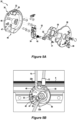
- the descender 20 is illustrated in exploded Figure 5A , illustrating all of the components therein.
- the descender comprises a cylindrical body 21 sealed with a disc-like closing plate or outer cover 26.
- the body 21 is rigidly mounted to the fall control ladder 100 at a lower end 3, such that a user or operator can access the descender 20 from the ground G.
- the outer cover 26 is rotatably mounted to the descender body 21 and is co-axially aligned to rotate about the body 21 around a central axis 32.
- the outer cover 26 comprises a slot 28. As the cover 26 is rotated about the body 21, the slot 28 can be brought into alignment with each of an inlet 38 for the cord 10 and an outlet 40 for the cord 10.
- a locking member illustrated in Figure 5A as a thumb lever 36, which locks the outer cover 26 to the body 21 and prevents rotation of the cover 26 relative to the body 21.
- the thumb lever 36 and a release lever 34 must be activated simultaneously to enable the cover plate 26 to rotate from its home position. This provides a double-action that is required to release the descender 20 as a safety feature that guards against accidental activation of the release.
- the body 21 has an outer wall 22 in which the keyed-hole 30 is located for receiving the termination end 12 of the cord 10.
- the outer wall 22 is not continuous and provides a first opening for the cord inlet 38, a second opening for the cord outlet 40 and a third outlet bridged by a release lever 34.
- the release lever 34 is pivotally mounted to the body 21 and when bridging the surface 22 of the body 21, locks the cord 10 within the descender 20. When the release lever 34 is pivoted away from the outer wall 22 to an approximate 90 degrees angle, extending away from the body 21, the descender is released and the cord 10 is free to move through the descender 20.
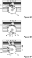
- a channel 48 Inside the body 21 of the descender 20 is a channel 48.
- the winding channel 48 turns between the cord inlet 38 and outlet 40.
- the cord 10 as it passes through the channel 48 is wound partially about a locking member 35.
- the channel 48 changes direction within the body 21 of the descender 20 three opposing times. The first turn is immediately on entry to the channel 48. The channel 48 then takes a second turn about a large U-bend around the locking member 35. The third and final turn is a tight turn immediately adjacent the outlet 40. These three turns result in an Ox Bow shape to the channel 48.
- the locking member 35 is coaxially aligned to rotate about the central axis 32 of the descender 20, which allows the locking member 35 to pivot between a locked position ( Figure 5B ) and a released position ( Figure 5C ).
- the locking member 35 is shaped like a guitar-body.
- the locking member 35 has a large rounded base portion that forms the U-bend (or pulley) about which the cord 10 is looped.
- the base portion can be shaped to provide a smooth arc sheave 49 that the cord 10 passes around between the inlet 38 and outlet 40.
- the sheave 49 can be V-shaped providing a recess in which the cord 10 sits around the base of the locking member 35.
- a nose 31 On an opposing side of the locking member 35 there is provided a nose 31.
- the nose 31 protrudes from the locking member 35 towards the outer wall 22 of the body 21, and imposes on the channel 48 adjacent the cord outlet 40.
- a bulging portion 22a of the outer wall 22 protrudes into the channel 48 immediately adjacent the outlet 40 to further shape the channel 48 into the Ox Bow shape.
- the bulge 22a forms a pinch point on the cord 10 in conjunction with the nose 31.
- a corresponding bulge 22b is also configured immediately adjacent the cord inlet 38, protruding into the channel 48. This forces the cord 10 into a tight bend immediately on entering the channel 48, to provide control of the cord 10 movement through the channel 48.
- the nose 31 further comprises a notch 50, shown in Figure 5D as a V-shape notch that is forced against the cord 10 as the nose 31 is pushed outwardly toward the bulging form 22a of the outer wall 22.
- the nose 31 of the locking member 35 in conjunction with notch 50 traps the cord 10 against the bulge 22a in the outer wall 22 preventing the cord 10 from traveling through the descender 20.
- the notch 50 can be tailored in shape and dimensions to provide a specific grip for a specific system allowing a fine tuning of the fall control ladder 100.
- the locking member 35 further comprises a shoulder 33 located on a periphery of the locking member, away from the nose 31 and the arc sheave 49.
- the shoulder 33 extends radially outwards away from the central axis 32 and towards the release lever 34 in the wall 22 of the body 21.
- a distal lip 45 of the release lever 34 is brought into contact with the nose 31 of the locking member 35.
- the distal lip 45 thus rotates the locking member 35 and pulls the nose 31 away from the outer wall 22 of the body 21, thereby puling the nose 31 off the cord 10.
- the notch 50 is lifted off the cord 10
- the friction on the cord 10 reduces and the cord 10 is free to move along the channel 48 and through the descender 20.
- a pair of cord guides within the body 21 of the descender 20 are a pair of cord guides, an upper guide 46 and a lower guide 47.
- the upper guide 46 is located between the release lever 34 and the cord inlet 38 and guides the cord 10 into the channel 48.
- the lower guide 47 is located between the release lever 34 and the cord outlet 40 and guides the cord 10 out of the channel 48.
- the release lever 34 When the descender 20 is to be locked, the release lever 34 is pushed back toward the body 21 and into position within the wall 22.
- the release lever 34 can be spring-loaded such that as soon as pressure is released from the lever 34, the lever 34 will return to the locked configuration, in place in the wall 22 of the descender 20.
- a work positioning hook 18, that is located in proximity to the arrestor 15 on the cord 10.
- a keeper hook (illustrated as a carabiner 17) attached to the cord 10 to mark the correct attachment location on the cord 10 (particularly the cord 10a that extends upwardly from the termination end 12 toward the second, upper mount 9). If a user accidentally attached the arrestor 15 to the cord 10b, releasing the cord 10 through the descender 20 will not arrest the user as anticipated. Additionally, it will not facilitate the lowering of an incapacitated user.
- the work positioning hook 18 Connecting the work positioning hook 18 with the eyelet 52 will comfortable support the user laterally, allowing the user to easily use two hands whilst performing work from the ladder 100.
- the work positioning hook 18 limits the reach of the user from the centre of the fall control ladder 100. This reduced the opportunity for the user to overreach and destabilise the fall control ladder 100 while supported thereon.
- the work positioning hook 18 is not a component of the fall arrest system but provides safety benefits to the fall control ladder 100 by aiding in loading the system centrally and prevents user falling sideway to a greater degree.
- a tether system is advised to improve the stability of the ladder footing and to tether the ladder 1 to a fixed anchor point.
- the tether system provides a safety improvement whether applied to a ladder 1 or a fall control ladder 100.
- the tether system described herein is integrally mounted to the stiles 2 of the ladder 1 and are thus always to hand when required. As the tether system is integral to the ladder, there are a number of stowage features to stow the tether system when not in use or when the ladder 1 is in transit. As the tether system is always available it is more likely to be deployed and becomes integrated into standard work practices.
- the tether system requires an anchor illustrated as tether point 27 to tether to.
- This may be a temporary fixing such as a pile of stake or can be a permanent fixing such as bolt or ring sunk into the concrete of the wall W or the ground G.
- the ladder 100 having a tether system for tethering to tether point 27, comprising: a ladder 1; a brake 25 mounted towards an upper end 4 of the ladder 1; a coupling 24 mounted towards a bottom end 3 of the ladder 1; and a cord 23 extending from the coupling 24 to the brake 25 via the tether point 27, wherein the brake 25 has an operative configuration for holding tension on the cord 23 against the tether point 27 and an inoperative configuration allowing the cord 23 to pass through the brake 25.
- the brake 25 in the operative configuration tensions the cord 23 against the tether point 27, such that a horizontal force is applied by the cord 23 pulling the ladder 1 toward the tether point 27, and a vertical force is applied pulling the ladder 1 toward the ground G on which the ladder 1 is supported.
- first coupling 24 is mounted toward the lower end 3 of the ladder 1, and the brake 25 is mounted above the first coupling 24 towards the upper end 4 of the ladder 1.
- first and second mounting can be reversed, without departing from the tether system as described.
- the brake 25 comprises a body 57 having a rope guide 58 therein. Co-axially pivoting about a rotation axis 61 is a locking member 59.
- the locking member 59 is not symmetrical about the rotational axis 61 and provides an offset bulging surface forming a cam 63.
- a first peripheral surface of the locking member 59 provides a pulley 59a, with a V-shape cut into the surface for the cord 23 to sit within. The V-shape cut helps to provide tension on the cord from the pulley 59a.
- the locking member 59 On a second peripheral surface, the locking member 59 has a plurality of teeth 62 located in opposition to the rope guide 58.
- the tether cord 23 is threaded through the body 57, into a tether inlet 66 over the pulley 59a of the locking member 59 past the teeth 62 and out of a tether outlet 68.
- the locking member 59 also comprises a release lever 60, extending from the body 57 to be externally accessible to a user to unlock the brake 25 as required.
- the brake 25 is locked, with the release lever 60 located centrally extending from the brake 25.
- the teeth 62 of the locking member 59 are biting into the tether cord 23 against the rope guide 58 locking the tether cord 23.
- Tether cord 23a is illustrated entering the brake 25, while tether cord 23b is illustrated exiting the brake 25.
- Pulling on cord 23b will allow the cord 23 to flow through the second mount 23, increasing the tension in the tether cord 23a and 23c, thus increasing the forces in the cord 23c pulling the ladder 1 towards the tether point 27 and increasing the forces in the cord 23a pulling the ladder towards the ground G and the tether point 27.
- a spring-loaded mechanism can be used to hold and release the locking member 59 from the tether cord 23, or as illustrated in Figure 8D , the release levers 60 is pulled or pushed by a user to disengage the plurality of teeth 62 from the tether cords 23.
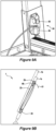
- a stowage loop 64 for stowing a closed hook On the outside of the brake 25 is a stowage loop 64 for stowing a closed hook, or carabiner 65 (illustrated in Figure 8E ).
- the carabiner 65 is used to connect the tether cord 23 to the fixed tether point 27.
- the carabiner 65 can be slotted through the brake 25 for stowage.
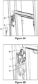
- the end of the tether cord 23 is tied-off on the first coupling 24, illustrated in Figure 9A .
- the first coupling 24 comprises a closed eyelet as a tie-off point 54 for the tether cord 23. It is contemplated that the first coupling 24 can be configured with a keyway similar to the keyed-hole 30 for receiving a termination end of the tether cord 23. Due to the reduced loading on the tether cord 23, in this embodiment, the tether cord is knotted to the tie-off point 54.
- the first coupling 24 also comprises an open hook 55 for stowing the tether cord 23 with the ladder 1, when the tether system is not deployed.
- Figure 9B is a schematic illustration of the tether rope 23 in a stowed configuration attached to a portion of the ladder 1.
- the ladder 1 of Figure 9B has a base portion 1a and a moveable portion 1b, such that the moveable portion 1b can be translated along base portion 1a, to extend the ladder 1.
- the tether cord 23 is tied-off at the first, bottom coupling 24 (illustrated in perspective view in Figure (9A ).
- the cord 23 extends from the first coupling 24 to a hook (carabiner 65) which is releasably stowed on the brake 25. After passing through the carabiner 65, the cord 23 extends along the ladder 1, back towards the open hook 55 of the first, bottom coupling 24. After passing around the hook 55, the cord 23 extends back towards the brake 25 and into the body 57 to engage with the rope guide 58 and teeth 62 of the locking member 59.
- a free end 51 of tether cord 23 extends from the body 57 and is pulled to tension the cord 23 against the locking member 59, thereby applying tension to each of sections 23a and 23c of tether cord 23.
- This tether cord 23 arrangement can be duplicated on both stiles 2 of the ladder 1 for increased stability.
- Each of the brake 25, first coupling 24 and all components thereof are duplicated on opposing stiles 2 of the ladder 1, although a single fixed tether point 27 can be shared between the tethers.
- the first coupling 24 and the brake 25 are mounted on the rear face of the ladder 1 (the read face facing the support wall and not the user). This avoids a tripping hazard for the user when ascending and descending the ladder 1. Furthermore, this avoid entanglement of the tether cord 23 with the cord 10 of the fall control ladder 100, which is predominantly mounted on the front side of the fall control ladder 100 (that side facing the user as the ascend and descend).
- the attachment point When using the tether point 27 in the ground G, the attachment point should be located greater than 0.8 mm away from the ladder feet 8.
- the tether point 27 When connecting to the tether point 27 in a wall, the tether point 27 should be located between 0-1.2m from the ground G (illustrated in Figure 10B as the shaded wall region). The tether point 27 should be capable of sustaining a tension of about 100kg. The tether point should be tested, to 100kg (1000N) before use, to validate the system before the user leaves the ground. The feet 8a of the ladder 1 should be placed not less than 0.8 m away from the wall, as indicated in the broken line (dot-dashed line) of Figure 10B .
- Figure 10C is a schematic representation of the ladder 1 tethered to a ground anchor shown as tether point 27, and two arrows to indicate the common failure modes of the ladder, in use.
- FIG 10D is a perspective view of the ladder 1 with arrows (3) to indicate the lateral movement reduced by the tether system fixed to the tether point 27.
- This lateral movement can be referred to as "sway".
- the sway increases with distance from the ground G or substrate on which the ladder 1 is supported.
- the cord 10 provides a life-line, and in combination with the harness 14, the arrestor 15 and the descender 20, the user will be prevented from falling to the ground, held stationary on the cord 10, and can be controllably lowered to the ground through the descender 20. Furthermore, the operator of the descender 20 (rescuer R) does not need to be elevated or to ascend the fall control ladder 100, as the operation of the descender 20 is from the ground G (or level at which the descender 20 is located towards the first end 3 of the fall control ladder 100), see Figures 11A and 11B .
- a method of retrieving a user from the fall control ladder comprises the following steps: tensioning the free end of the chord 10c before pivoting the release lever away from the descender 20, allowing the cord 10 to flow through the channel and thereby lowering the user attached to cord 10a via the arrestor.
- the speed of the user's descent can be adjusted by varying the speed that the rope flows through the user's hand.
- the descent can be halted at any time, by releasing the lever 34 and returning the descender to the locked configuration wherein tension on the cord 10 is maintained.
Landscapes
- Engineering & Computer Science (AREA)
- Mechanical Engineering (AREA)
- Architecture (AREA)
- General Engineering & Computer Science (AREA)
- Health & Medical Sciences (AREA)
- General Health & Medical Sciences (AREA)
- Business, Economics & Management (AREA)
- Emergency Management (AREA)
- Civil Engineering (AREA)
- Structural Engineering (AREA)
- Ladders (AREA)
Claims (15)
- Échelle dotée d'un système anti-chute (100), comprenant :une échelle (1) ;un tendeur (20) ;un support (9) monté vers l'extrémité supérieure de l'échelle ;un câble (10) qui s'étend à partir du tendeur et au-dessus du support dans une configuration en boucle ; etun dispositif d'arrêt (15) engagé de manière mobile avec le câble pour coupler un utilisateur au câble,dans lequel le tendeur a une configuration verrouillée pour maintenir la tension sur le câble afin de supporter le poids de l'utilisateur et une configuration ouverte pour permettre au câble de passer à travers le tendeur,caractérisé en ce que le tendeur est monté sur l'échelle à une hauteur accessible à l'utilisateur depuis le sol sur lequel repose l'échelle, et par le fait qu'en cas de chute, un opérateur au sol peut relâcher la corde de manière commandée par l'intermédiaire du tendeur pour ramener l'utilisateur vers le sol par l'intermédiaire du dispositif d'arrêt.
- Échelle de la revendication 1, dans laquelle le câble comprend une extrémité fixe fixée au tendeur et une extrémité libre qui passe à travers le tendeur pour faire varier la longueur du câble dans le système anti-chute.
- Échelle de la revendication 1 ou de la revendication 2, dans laquelle le dispositif d'arrêt est couplé à un harnais de sécurité pour y attacher l'utilisateur.
- Échelle de l'une des revendications 1 à 3, dans laquelle le dispositif d'arrêt fournit une configuration active dans laquelle le dispositif d'arrêt se verrouille sur le câble et maintient ainsi l'utilisateur à un point fixe sur le câble.
- Échelle de l'une des revendications 1 à 4, dans laquelle le tendeur est configuré pour recevoir et capturer la section médiane du câble entre une entrée et une sortie du tendeur.
- Échelle de l'une des revendications 1 à 5, dans laquelle l'échelle est une échelle extensible.
- Échelle de l'une quelconque des revendications 1 à 6, comprenant en outre un système d'attache pour s'attacher à une ancre, comprenant :un frein monté vers une extrémité supérieure de l'échelle ;un accouplement monté vers l'extrémité inférieure de l'échelle ; etune corde allant de l'accouplement au frein en passant par le point d'ancrage,dans lequel le frein a une configuration opérationnelle pour maintenir la tension sur la corde contre l'ancre et une configuration inopérante permettant à la corde de passer à travers le frein.
- Échelle de la revendication 7, dans laquelle le frein en configuration opérationnelle tend la corde contre l'ancre, de sorte qu'une première force est appliquée par la corde tirant l'échelle vers l'ancre et une deuxième force est appliquée tirant l'échelle vers le sol sur lequel l'échelle est supportée.
- Échelle de la revendication 8, dans laquelle la première force agit dans une direction sensiblement horizontale et la deuxième force agit dans une direction sensiblement verticale.
- Échelle de l'une des revendications 7 à 9, dans laquelle le frein fournit une entrée pour recevoir la corde et une sortie par laquelle une extrémité libre de la corde sort du frein, de sorte qu'une force appliquée à l'extrémité libre de la corde tend la corde contre l'ancre, la tension sur la corde étant maintenue par le frein.
- Échelle de l'une quelconque des revendications 7 à 10, dans laquelle le frein comprend un actionneur permettant de sélectionner entre la configuration opérationnelle et la configuration inopérante du frein.
- Échelle de l'une quelconque des revendications 1 à 11, dans laquelle le tendeur comprend :un corps ayant une entrée et une sortie interconnectées par un canal interne qui s'étend à travers le corps pour recevoir le câble ;le canal interne est défini par une paroi et un élément de verrouillage rotatifdans lequel la tension du câble dans une première direction applique une force à l'élément de verrouillage rotatif, poussant l'élément de verrouillage dans le canal etempêchant le mouvement du câble dans le canal en plaçant le tendeur dans la configuration verrouillée par défaut, etdans lequel la tension sur le câble dans une deuxième direction opposée applique une force à l'élément de verrouillage rotatif, poussant l'élément de verrouillage hors du canal pour placer le tendeur dans la configuration ouverte.
- Échelle de la revendication 12, dans laquelle le mouvement du câble dans la première direction applique la force à l'élément de verrouillage rotatif, empêchant ainsi le mouvement du câble à travers le canal.
- Échelle de la revendication 12, dans laquelle le mouvement du câble dans la deuxième direction opposée relâche la force sur l'élément de verrouillage rotatif, dégageant ainsi le canal et permettant le mouvement du câble à travers le canal.
- Échelle l'une quelconque des revendications 12 à 14, dans laquelle le canal interne est en forme d'arc de boeuf.
Applications Claiming Priority (2)
| Application Number | Priority Date | Filing Date | Title |
|---|---|---|---|
| AU2018901797A AU2018901797A0 (en) | 2018-05-22 | Fall Control Ladder | |
| PCT/AU2019/050491 WO2019222799A1 (fr) | 2018-05-22 | 2019-05-21 | Échelle anti-chute |
Publications (4)
| Publication Number | Publication Date |
|---|---|
| EP3797202A1 EP3797202A1 (fr) | 2021-03-31 |
| EP3797202A4 EP3797202A4 (fr) | 2021-07-07 |
| EP3797202C0 EP3797202C0 (fr) | 2023-10-11 |
| EP3797202B1 true EP3797202B1 (fr) | 2023-10-11 |
Family
ID=68615500
Family Applications (1)
| Application Number | Title | Priority Date | Filing Date |
|---|---|---|---|
| EP19807307.4A Active EP3797202B1 (fr) | 2018-05-22 | 2019-05-21 | Échelle anti-chute |
Country Status (4)
| Country | Link |
|---|---|
| US (1) | US20210372200A1 (fr) |
| EP (1) | EP3797202B1 (fr) |
| AU (1) | AU2019275480A1 (fr) |
| WO (1) | WO2019222799A1 (fr) |
Families Citing this family (6)
| Publication number | Priority date | Publication date | Assignee | Title |
|---|---|---|---|---|
| DE102014112403B4 (de) * | 2014-08-28 | 2017-06-01 | Bornack Gmbh & Co. Kg | Abseilfluchtsystem |
| US20210002959A1 (en) * | 2019-07-06 | 2021-01-07 | Ashot Aroian | Fire Escape Device (Ladders with Safety Cord and Fall Arrest System) |
| US11492849B2 (en) | 2020-01-31 | 2022-11-08 | Charles J. Mackarvich | Ladder dock |
| US11781851B2 (en) * | 2020-03-04 | 2023-10-10 | Darrell Bijl | Alignment tool |
| CN114086789B (zh) * | 2021-11-29 | 2023-02-03 | 鹏盛建设集团有限公司 | 一种建筑施工用建筑构件的防坠装置 |
| US11719042B1 (en) * | 2022-02-15 | 2023-08-08 | Charles J. Mackarvich | Fall arrest shock dampener |
Family Cites Families (7)
| Publication number | Priority date | Publication date | Assignee | Title |
|---|---|---|---|---|
| US4899847A (en) * | 1988-01-25 | 1990-02-13 | Lufkin Elmer S | Mobile supports |
| AU2003206686A1 (en) * | 2002-02-25 | 2003-09-09 | Avanti Stigefabrik A/S | Ladder climbing assistance device |
| US8348014B2 (en) * | 2009-06-26 | 2013-01-08 | Verizon Patent And Licensing Inc. | Fall-arrest ladder system |
| JP5437296B2 (ja) * | 2010-03-01 | 2014-03-12 | 金治 大塩 | クライミング用ロープの制動装置 |
| ES2385530B1 (es) * | 2012-03-13 | 2013-05-31 | Escaleras Aguerri, S.L. | Línea de vida vertical para trabajos en altura |
| GB2502812A (en) * | 2012-06-07 | 2013-12-11 | Joseph Allan Shaw | Apparatus for securing and tethering an object |
| CN105980652B (zh) * | 2013-09-18 | 2018-03-02 | 伟英企业有限公司 | 包括绳索滑轮系统以及坠落保护的梯子 |
-
2019
- 2019-05-21 EP EP19807307.4A patent/EP3797202B1/fr active Active
- 2019-05-21 WO PCT/AU2019/050491 patent/WO2019222799A1/fr unknown
- 2019-05-21 AU AU2019275480A patent/AU2019275480A1/en active Pending
- 2019-05-21 US US17/054,416 patent/US20210372200A1/en active Pending
Also Published As
| Publication number | Publication date |
|---|---|
| EP3797202C0 (fr) | 2023-10-11 |
| EP3797202A4 (fr) | 2021-07-07 |
| US20210372200A1 (en) | 2021-12-02 |
| WO2019222799A1 (fr) | 2019-11-28 |
| EP3797202A1 (fr) | 2021-03-31 |
| AU2019275480A1 (en) | 2020-11-26 |
Similar Documents
| Publication | Publication Date | Title |
|---|---|---|
| EP3797202B1 (fr) | Échelle anti-chute | |
| US5131491A (en) | Descent controller | |
| US11697965B2 (en) | Ladder safely mechanisms | |
| EP3047090B1 (fr) | Échelles comprenant un système de corde et poulies et un dispositif de protection contre les chutes | |
| US8348014B2 (en) | Fall-arrest ladder system | |
| EP1642621B1 (fr) | Système de sauvetage avec un frein de cable et dispositif d'ancrage | |
| US5038888A (en) | Descent controller | |
| US8997928B1 (en) | Fall restraint traveler device | |
| US20140048353A1 (en) | Aerial ladder safety device | |
| US20160206902A1 (en) | Fire escape emergency descent system (eds) | |
| US4139079A (en) | Flexible stile or rope ladder for climbing poles or like members | |
| JP4287018B2 (ja) | 梯子 | |
| WO2007004934A1 (fr) | Système et procédé pour le sauvetage d’occupants situés en hauteur | |
| GB2590609A (en) | Remote clipping device | |
| JP2006158229A (ja) | 樹上作業の墜落防止方法 | |
| JP2020019638A (ja) | ロープ牽引装置 | |
| KR20240020838A (ko) | 드래그 다운먼트 | |
| CA2080715A1 (fr) | Plate-forme de travail suspendue avec cordage de securite | |
| EP2883574B1 (fr) | Dispositif de délai | |
| EP4045153A1 (fr) | Descendeurs de câble | |
| PH12014000280A1 (en) | Fire escape by three pulleys |
Legal Events
| Date | Code | Title | Description |
|---|---|---|---|
| STAA | Information on the status of an ep patent application or granted ep patent |
Free format text: STATUS: THE INTERNATIONAL PUBLICATION HAS BEEN MADE |
|
| STAA | Information on the status of an ep patent application or granted ep patent |
Free format text: STATUS: THE INTERNATIONAL PUBLICATION HAS BEEN MADE |
|
| PUAI | Public reference made under article 153(3) epc to a published international application that has entered the european phase |
Free format text: ORIGINAL CODE: 0009012 |
|
| STAA | Information on the status of an ep patent application or granted ep patent |
Free format text: STATUS: REQUEST FOR EXAMINATION WAS MADE |
|
| 17P | Request for examination filed |
Effective date: 20201106 |
|
| AK | Designated contracting states |
Kind code of ref document: A1 Designated state(s): AL AT BE BG CH CY CZ DE DK EE ES FI FR GB GR HR HU IE IS IT LI LT LU LV MC MK MT NL NO PL PT RO RS SE SI SK SM TR |
|
| AX | Request for extension of the european patent |
Extension state: BA ME |
|
| A4 | Supplementary search report drawn up and despatched |
Effective date: 20210609 |
|
| RIC1 | Information provided on ipc code assigned before grant |
Ipc: E06C 7/18 20060101AFI20210602BHEP Ipc: E06C 5/36 20060101ALI20210602BHEP Ipc: E04G 21/32 20060101ALI20210602BHEP Ipc: E06C 1/12 20060101ALI20210602BHEP Ipc: E06C 7/14 20060101ALI20210602BHEP Ipc: E06C 7/42 20060101ALI20210602BHEP Ipc: E06C 7/44 20060101ALI20210602BHEP Ipc: E04G 5/00 20060101ALN20210602BHEP |
|
| DAV | Request for validation of the european patent (deleted) | ||
| DAX | Request for extension of the european patent (deleted) | ||
| GRAP | Despatch of communication of intention to grant a patent |
Free format text: ORIGINAL CODE: EPIDOSNIGR1 |
|
| RIC1 | Information provided on ipc code assigned before grant |
Ipc: E04G 5/00 20060101ALN20230522BHEP Ipc: E06C 7/44 20060101ALI20230522BHEP Ipc: E06C 7/42 20060101ALI20230522BHEP Ipc: E06C 7/14 20060101ALI20230522BHEP Ipc: E06C 1/12 20060101ALI20230522BHEP Ipc: E04G 21/32 20060101ALI20230522BHEP Ipc: E06C 5/36 20060101ALI20230522BHEP Ipc: E06C 7/18 20060101AFI20230522BHEP |
|
| STAA | Information on the status of an ep patent application or granted ep patent |
Free format text: STATUS: GRANT OF PATENT IS INTENDED |
|
| INTG | Intention to grant announced |
Effective date: 20230629 |
|
| RIC1 | Information provided on ipc code assigned before grant |
Ipc: E04G 5/00 20060101ALN20230619BHEP Ipc: E06C 7/44 20060101ALI20230619BHEP Ipc: E06C 7/42 20060101ALI20230619BHEP Ipc: E06C 7/14 20060101ALI20230619BHEP Ipc: E06C 1/12 20060101ALI20230619BHEP Ipc: E04G 21/32 20060101ALI20230619BHEP Ipc: E06C 5/36 20060101ALI20230619BHEP Ipc: E06C 7/18 20060101AFI20230619BHEP |
|
| GRAS | Grant fee paid |
Free format text: ORIGINAL CODE: EPIDOSNIGR3 |
|
| GRAA | (expected) grant |
Free format text: ORIGINAL CODE: 0009210 |
|
| STAA | Information on the status of an ep patent application or granted ep patent |
Free format text: STATUS: THE PATENT HAS BEEN GRANTED |
|
| AK | Designated contracting states |
Kind code of ref document: B1 Designated state(s): AL AT BE BG CH CY CZ DE DK EE ES FI FR GB GR HR HU IE IS IT LI LT LU LV MC MK MT NL NO PL PT RO RS SE SI SK SM TR |
|
| REG | Reference to a national code |
Ref country code: GB Ref legal event code: FG4D |
|
| REG | Reference to a national code |
Ref country code: CH Ref legal event code: EP |
|
| REG | Reference to a national code |
Ref country code: DE Ref legal event code: R096 Ref document number: 602019039256 Country of ref document: DE |
|
| REG | Reference to a national code |
Ref country code: IE Ref legal event code: FG4D |
|
| U01 | Request for unitary effect filed |
Effective date: 20231101 |
|
| U07 | Unitary effect registered |
Designated state(s): AT BE BG DE DK EE FI FR IT LT LU LV MT NL PT SE SI Effective date: 20231107 |
|
| PG25 | Lapsed in a contracting state [announced via postgrant information from national office to epo] |
Ref country code: GR Free format text: LAPSE BECAUSE OF FAILURE TO SUBMIT A TRANSLATION OF THE DESCRIPTION OR TO PAY THE FEE WITHIN THE PRESCRIBED TIME-LIMIT Effective date: 20240112 |
|
| PG25 | Lapsed in a contracting state [announced via postgrant information from national office to epo] |
Ref country code: IS Free format text: LAPSE BECAUSE OF FAILURE TO SUBMIT A TRANSLATION OF THE DESCRIPTION OR TO PAY THE FEE WITHIN THE PRESCRIBED TIME-LIMIT Effective date: 20240211 |