EP3796362A1 - Procédé de traitement au plasma d'un substrat dans une chambre à plasma et système de traitement au plasma - Google Patents
Procédé de traitement au plasma d'un substrat dans une chambre à plasma et système de traitement au plasma Download PDFInfo
- Publication number
- EP3796362A1 EP3796362A1 EP19461583.7A EP19461583A EP3796362A1 EP 3796362 A1 EP3796362 A1 EP 3796362A1 EP 19461583 A EP19461583 A EP 19461583A EP 3796362 A1 EP3796362 A1 EP 3796362A1
- Authority
- EP
- European Patent Office
- Prior art keywords
- power supply
- plasma
- feature
- plasma processing
- parameter
- Prior art date
- Legal status (The legal status is an assumption and is not a legal conclusion. Google has not performed a legal analysis and makes no representation as to the accuracy of the status listed.)
- Withdrawn
Links
Images


Classifications
-
- H—ELECTRICITY
- H01—ELECTRIC ELEMENTS
- H01J—ELECTRIC DISCHARGE TUBES OR DISCHARGE LAMPS
- H01J37/00—Discharge tubes with provision for introducing objects or material to be exposed to the discharge, e.g. for the purpose of examination or processing thereof
- H01J37/32—Gas-filled discharge tubes
- H01J37/32009—Arrangements for generation of plasma specially adapted for examination or treatment of objects, e.g. plasma sources
- H01J37/32018—Glow discharge
- H01J37/32036—AC powered
-
- H—ELECTRICITY
- H01—ELECTRIC ELEMENTS
- H01J—ELECTRIC DISCHARGE TUBES OR DISCHARGE LAMPS
- H01J37/00—Discharge tubes with provision for introducing objects or material to be exposed to the discharge, e.g. for the purpose of examination or processing thereof
- H01J37/32—Gas-filled discharge tubes
- H01J37/32917—Plasma diagnostics
- H01J37/32935—Monitoring and controlling tubes by information coming from the object and/or discharge
- H01J37/32944—Arc detection
-
- H—ELECTRICITY
- H01—ELECTRIC ELEMENTS
- H01J—ELECTRIC DISCHARGE TUBES OR DISCHARGE LAMPS
- H01J37/00—Discharge tubes with provision for introducing objects or material to be exposed to the discharge, e.g. for the purpose of examination or processing thereof
- H01J37/32—Gas-filled discharge tubes
- H01J37/34—Gas-filled discharge tubes operating with cathodic sputtering
-
- H—ELECTRICITY
- H01—ELECTRIC ELEMENTS
- H01J—ELECTRIC DISCHARGE TUBES OR DISCHARGE LAMPS
- H01J2237/00—Discharge tubes exposing object to beam, e.g. for analysis treatment, etching, imaging
- H01J2237/32—Processing objects by plasma generation
- H01J2237/33—Processing objects by plasma generation characterised by the type of processing
- H01J2237/332—Coating
Definitions
- the invention relates to a method of plasma processing a substrate in a plasma chamber, comprising the steps of supplying a power supply signal to the plasma chamber in order to form a plasma in the plasma chamber and monitoring at least one parameter related to the plasma processing.
- the invention relates to a plasma processing system, in particular, in which the inventive method is implemented.
- Crazing defects were first identified in large-area sputtering processes driven by AC power supplies. The defects occur on the substrate and lead to damaging the substrate such as architectural glass as described in more detail e.g. in US 2018/0040461 A1 . Crazing occurs depending on the power supply used (medium frequency (MF) power supply or DC bipolar power supply, also called bipolar power supply, both a form of AC power supplies). If the occurrence of crazing is detected, different actions can be taken, for example thorough mechanical cleaning of the vacuum chamber components, grounding/insulation of rollers, careful treatment of the glass edges, covering rollers with a synthetic fiber, use of an auxiliary anode biased positively with respect to ground level, or changing the coater geometry. Proper cleanliness of the vacuum chamber is mentioned as one of the most important issues.
- MF medium frequency
- the object of the present invention is to provide a method and a system which eliminate or at least dramatically decrease the occurrence of crazing.
- the invention relates to a method of plasma processing a substrate in a plasma chamber, comprising the steps of
- the inventive method is applied before crazing even occurs. Therefore it is possible to eliminate or at least dramatically decrease the damage of the substrate due to crazing.
- the power supply may be designed to deliver AC power with more than 500 W, in particular more than 5 kW and typically more than 50 kW.
- the power supply may be designed to deliver AC power in a frequency range between 1 kHz and 200 kHz, in particular between 5 kHz and 100 kHz.
- the output power of the power supply may be connected to two targets in the plasma chamber, so that both targets may be driven as cathodes and anodes alternately.
- the power supply signal that is adjusted may be a current-, a voltage-, or a power-controlled signal.
- a current-controlled signal may be a current-controlled signal.
- the monitored parameter can be for example voltage, current, power, reflected waves (at a basic frequency or other frequency) and/or, or a combination of the aforementioned as, for example, the impedance of the plasma process.
- the monitored parameter may be different from the power supply signal that is adjusted.
- the monitored parameter may be a voltage.
- the monitored parameter may be a current.
- the monitored parameter can be the voltage of one of the targets against the potential of the plasma chamber, which may be ground or earth.
- the monitored parameter can additionally be the voltage of the other target against the potential of the plasma chamber, which may be ground or earth.
- the monitored parameter can be in particular the voltage between the two targets in the plasma chamber.
- the monitored parameter may also be a parameter measured in the plasma chamber or aside the plasma chamber, for example through a window.
- the monitored or measured parameter may be light, pressure, discharge, electrical, or magnetic field strength or another signal in the plasma chamber.
- the monitored parameter can be measured with a sampling rate which is higher than the frequency of the AC power supply, in particular more than ten times higher than the frequency of the AC power supply.
- the monitored parameter may be a derivate of a measured value. Then also the velocity or rate of change in a measured value may be the source for the determination of the feature.
- the monitored parameter may be a filtered value. Then also a part of the frequency spectrum in a measured value may be the source for the determination of the feature.
- the monitored parameter may be a time framed value. That should mean that a predefined time frame is laid over the measured value, and only a time interval of the measured value will be the source for the determination of the feature.
- the feature may be one or more or a combination of the following:
- the feature may be a value.
- the value may reach or exceed a threshold value.
- the feature related to the at least one monitored parameter can be a feature derived directly from the monitored parameter, in particular a maximum or minimum of the monitored parameter. Alternatively, the feature can be obtained after processing the monitored parameter. Examples for determining the feature can be found for example in US 8007641 B2 , DE 10 2011 007 596 B3 , US 10209294 B2 , US 10181392 B2 , US 7640120 B2 , US 10290477 B2 , EP 2905802 B1 , EP 3234980 B1 , which are hereby incorporated by reference. But in contrast to those disclosures, the feature for this invention should not be understood to be a single event such as a voltage drop in the case of a sudden arc in plasma process. It may be a recurring event. It may be a periodic event, in particular with the period of the power supply, if the power supply signal is an AC signal.
- the feature may develop over time, for example after one or two hours in particular as a result of the contamination or impureness of the plasma chamber or an unwanted deposition of parts or tools in the plasma chamber.
- a method and/or system with machine learning algorithm and/or artificial intelligence algorithms may be used to identify the essential features and/or part of one or more monitored parameter(s).
- the event of crazing in the substrate should additionally be monitored and analysed. With that monitoring and analysis, a set of training- and test-data may be recorded. In such a way the method and the system may be trained and, in particular, checked and, in particular, continuously improved.
- inventive method in particular the method steps, may be performed without interrupting the plasma processing.
- At least one of an electrode-to-electrode potential and an electrode-to-ground potential are monitored.
- the target-to-target potential can be monitored.
- the target-to-ground potential can be monitored, if at least one electrode being a target is provided in the plasma chamber.
- Determining the feature may comprise comparing the at least one monitored parameter or a quantity derived therefrom with a threshold border.
- a threshold border may be one, or more, or a combination of the following:
- the threshold border may be derived by one, or more, or a combination of the following:
- the feature that is determined may be a maximum or minimum of the monitored parameter.
- the feature may be a maximum of a target-to-target potential or of an electrode-to-ground potential.
- determining the feature may comprise counting the number of times the at least one parameter or a quantity derived therefrom exceeds a threshold border in a given time interval. Hence, determining the feature corresponds to determining the number of times a predetermined event occurs in a given time interval. Determining such a feature has the effect that the monitored parameter is observed over a longer period of time and that the power supply signal is not adjusted too fast or too drastically.
- Adjusting the power supply signal may comprise applying several sets of parameters to produce the power supply signal, determining the effect of a particular set of parameters on the feature, and selecting the parameter set leading to the lowest feature for further plasma processing.
- the parameter sets that are applied to produce the power supply signal may be given.
- test runs may be performed to determine parameter sets that lead to a change in the feature.
- adjusting the power supply signal may comprise at least one of
- one of the parameters may have to be changed as well in order to keep the power constant.
- the duty cycle i.e. the waveform of the power supply signal component is changed
- the amplitude of the power supply signal component may have to be changed as well.
- the amplitude, waveform and frequency of a power supply signal component may be the parameter set or part of the parameter set applied for producing the power supply signal.
- At least some of the method steps may be performed in response to a user demand. For example, in the case of an older power supply, where monitoring and/or detecting can only be done using external equipment to determine the feature, the method can be triggered by a user.
- At least some of the method steps may be performed in response to detecting that at least one monitored parameter exceeds a threshold border.
- the improvement of the plasma processing process can be initiated if a monitored parameter exceeds a threshold border.
- the threshold border can be given, or user defined or determined by algorithm, such as a machine learning algorithm and/or artificial intelligence algorithms.
- the event of crazing in the substrate should additionally be monitored. With that monitoring and analysis, a set of training- and test-data may be recorded. In such a way the method and the system may be trained and, in particular, checked and, in particular, continuously improved.
- the method steps may be performed in response to statistical data obtained from a range of power supplies supplying power to a plasma process.
- inventive method can be activated as a background application and use statistical data from a range of power supplies available in a central processing system, in particular a cloud computing system, to perform sophisticated improvement and return settings to the power supply to regulate the operating parameters, such as voltage and/or current waveform, amplitude and frequency.
- the invention relates to a plasma processing system, comprising
- the at least one electrode may be a target.
- the sensor for measuring at least one plasma process parameter may be a voltage sensor, a current sensor, a directional coupler or the like.
- the determination unit to determine the feature may be a computational unit or a processor or a software application implemented in a computational unit.
- the determination unit may comprise a comparator comparing the at least one monitored parameter or a quantity derived therefrom to a threshold border. For example, a voltage or current may be compared to a threshold border.
- the determination unit may also comprise a counter, counting the number of times the monitored parameter or quantity derived therefrom exceeds the threshold border.
- the determination unit in particular the counter, may count, how often per unit time the target-to-target voltage rises above the threshold feature.
- the power supply may be an MF power supply.
- An MF power supply may be designed to deliver an output power where the output voltage and/or output current are formed sinusoidal.
- the power supply may also be a bipolar supply.
- a bipolar power supply may designed to deliver an output power where the output voltage and/or output current are formed rectangular or stepwise rectangular or in a predefined way as described in DE 10 2009 002 684 A1 or DE 10 2014 220 094 A1 which are hereby incorporated by reference.
- a bipolar supply has the advantage that the duty cycle, voltage and frequency can be adjusted without changing the power. In particular, the power can be kept constant. Thus the power delivered to the plasma process can be kept constant, but the parameters for creating the power can be adjusted. This can lead to the prevention of crazing.
- the power supply may be designed to balance the power between both outputs as described for example in EP 1 593 143 B1 which is hereby incorporated by reference.
- the bipolar power supply may be configured to supply power to two targets simultaneously.
- the bipolar power supply may be configured to supply a dual magnetron sputtering arrangement with power.
- the control unit may be integrated in the power supply or the control unit may be external to the power supply. If the control unit is external to the power supply it can be used for several power supplies.
- the sensor may be positioned at the power supply output or in the vicinity of the electrode, in particular in the vicinity of the target.
- the monitored parameter can be measured directly at the power supply output and/or on the target. In particular, the measurement can be taken at the closest point accessible for such measurements, for example at the cable connection to the target end-blocks.
- control unit which is configured to perform the inventive method, can actively minimize the root cause of crazing by minimizing the feature, in particular by minimizing the target-to-target potential and/or the target-to-ground potential.
- inventive method can be used as continuously adapting method.
- the control unit can thus continuously react to condition changes in the system, for example, due to progressive growth of a parasitic coating on system elements or cyclic modification of the working conditions of the power supply itself.
- the control unit may comprise a user interface for triggering an adjustment of the power supply signal.
- a user can trigger the inventive method by using the user interface.
- the plasma processing system may comprise several power supplies that exchange data with a cloud computing system. Hence, suitable parameters obtained for one power supply can be used for other power supplies, supplying power to similar plasma processes.
- Fig. 1 shows a plasma processing system 1.
- the plasma processing system 1 comprises a plasma chamber 6 for processing substrates 10, which are disposed on a substrate carrier 15.
- the plasma processing system 1 comprises a power supply 2 connected to electrodes 11, 12 via power lines 8, 9.
- the electrodes 11, 12 are arranged within the plasma chamber 6. By supplying power to the electrodes 11, 12 a plasma 7 may be formed and maintained in the plasma chamber 6.
- the electrodes 11, 12 may be rotating electrodes.
- the plasma may be enhanced by magnets; so that the plasma process may be a magnetron plasma process.
- the plasma process may be for sputtering material from electrodes 11, 12.
- Such electrodes 11, 12 in a plasma processing system 1 are also called target.
- the plasma processing system 1 may be designed for deposition of material on the substrate 10. It may be a PVD, CVD reactive plasma process or the like.
- the power supply 2 may be an AC power supply, delivering an AC Signal to both electrodes 11,12. Then both electrodes 11, 12 may work as cathodes and
- Crazing arc defects may occur on the surface of insulating materials during sputtering deposition and may damage the product, generating significant waste and financial losses in production.
- LAC Large Area Coating
- the crazing effect is not the only parameter influencing the quality of the product and the efficiency of the production process.
- the coating layer stack configuration includes sputtering from heavily arcing targets in reactive atmosphere indicators such as arc suppression efficiency or target condition must be taken into account.
- the improvement of the bipolar power supply settings for anode voltage minimization could include keeping the operation within the recommended parameter range. For example, if silicon targets are used for reactive sputtering of a SiO 2 layer the frequency can be varied in a range allowing operation without a risk of nodules formation. Nodules, an arc-related local damage, of target surface, may arise if arc suppression mechanisms are misused or the operation frequency is lower than a critical value.
- the plasma processing system 1 in Fig. 1 comprises also a monitor unit 3, which is configured to monitor a parameter such as voltage, current and/or power, or the like. It may comprise a voltage sensor, a current sensor and/ or a power sensor.
- the monitor unit 3 may also comprise an ADC, in particular with a high sampling rate as mentioned above.
- the plasma processing system 1 comprises also a determination unit 4, which is configured to determine a feature related to the at least one monitored parameter. This may comprise a comparator or software to compare the monitored parameter with a threshold border. In this way, the feature may be determined.
- the determination unit 4 may comprise a computer, a data memory and program memory, configured to operate software with algorithms to determine the feature. The variants of algorithms have been disclosed in detail above.
- the plasma processing system 1 comprises also an adjusting unit 5, configured to adjust the power supply signal at the output of the power supply 2.
- the power supply unit 1 may be a bipolar power supply unit, where several adjusting parameters are available, such as current, voltage, power, duty cycle, pulse-off time and shape of waveforms, such as rectangular, step-wise rectangular, trapeze- or sinus-shape or the like.
- the monitor unit 3, the determination unit 4, and the adjusting unit 5 may be all together or each part of the power supply 2a.
- a power supply 2a is drafted in dotted lines in Fig. 1 where all three units 3,4,5 are part of the power supply 2a.
- a control unit 13 comprises the adjusting unit 5. Additionally the control unit 13 may comprise the determination unit 4. Additionally the control unit 13 may comprise the monitor unit 3 at least partly
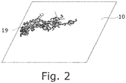
- Fig. 2 shows a typical crazing damage 19 on a glass substrate 10.
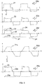
- Fig 3 shows five graphs over time t to explain the method steps of the invention.
- Graph 20a shows a power supply signal 21 which is led to the electrodes 11, 12 to maintain plasma 7.
- this is a current signal. It is a typical AC signal as it is delivered by a bipolar power supply.
- Graph 20b shows a monitored parameter 22 related to the plasma processing. This could be a current, voltage, or power signal. Advantageously this is a voltage signal, measured between electrode 11 or 12 and ground.
- Graph 20c shows again the monitored parameter 22. Additionally, two threshold values 23, 23a are shown as dotted lines. It can be seen that the monitored parameter 22 exceeds the threshold values 23, 23a periodically.
- the determination unit 4 determines a feature 24 related to the at least one monitored parameter 22.
- Graph 20d shows an adjusted power supply signal 21a, which has now trapeze-shape.
- Other shapes are also possible, but this shape is one example which seems in this or a similar way to be successful in improving the plasma supply system with reduced crazing.
- Graph 20e shows again a monitored parameter 22a. But this time it has changed as a result of the changed power supply signal 21a and the reaction of the plasma 7 inside the plasma chamber 6. It can be seen that the feature 24 from graph 20c has been reduced und the monitored parameter 22a does not exceed the threshold 23 anymore.
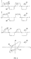
- Fig. 4 shows in four graphs 31 - 34 some typical forms of peculiarities
- Graph 30 shows a periodic parameter drop as a feature 24.
- a feature may be determined by a threshold border 23, but the monitored parameter must be a time framed part of the measured value.
- Graph 31 shows a ringing, oscillation, or ripple as a feature 24.
- a filter may be used.
- Graph 32 shows a stepwise rising with a sharp kink as a feature 24.
- a derivative of the measured value may be used as monitored parameter in order to determine the feature.
- Graph 33 shows a different view on measured values.
- the voltage over current is monitored in a graph.
- the expected form may be an ellipse which is driven a loop every period. So the threshold border 23 may be such an ellipse. With that a feature 24 may be detected as well.
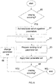
- Fig. 5 shows a flow chart of the method of plasma processing a substrate 2 in a plasma chamber 6.
- a power supply signal is supplied to the plasma chamber 6 in order to form a plasma 7 in the plasma chamber 6.
- step 52 at least one parameter related to the plasma processing is monitored.
- step 53 a feature 24 related to the at least one monitored parameter 22 is determined.
- step 54 the power supply signal is adjusted during the plasma processing to reduce the feature.
- Fig. 6 shows an additional flowchart of the inventive method. In this case it is checked at step 60 if a crazing can be detected. If a crazing is detected, the method according to claim 1 or to Fig. 5 is performed with a basic set of algorithm parameters being used. In step 63 the parameters are monitored as described in the method according to claim 1 or according to Fig. 5 . Step 62is repeated for a certain number of different sets of parameters. At step 63 a ranking list of parameter sets is created. In particular, a parameter set which leads to the lowest feature is selected. At step 64 the best ranked parameter set is used for adjusting the power supply signal. In step 65 again it is checked if a crazing can be detected. If yes, the parameter set is changed in step 66, and again it is monitored in step 62 and the process follows then from step 62 to 63 and so on. If not, the method may end.
Landscapes
- Engineering & Computer Science (AREA)
- Physics & Mathematics (AREA)
- Plasma & Fusion (AREA)
- Chemical & Material Sciences (AREA)
- Analytical Chemistry (AREA)
- Power Engineering (AREA)
- Plasma Technology (AREA)
Priority Applications (5)
| Application Number | Priority Date | Filing Date | Title |
|---|---|---|---|
| EP19461583.7A EP3796362A1 (fr) | 2019-09-23 | 2019-09-23 | Procédé de traitement au plasma d'un substrat dans une chambre à plasma et système de traitement au plasma |
| PCT/EP2020/076571 WO2021058566A1 (fr) | 2019-09-23 | 2020-09-23 | Procédé de traitement au plasma d'un substrat dans une chambre à plasma et système de traitement au plasma |
| EP20786441.4A EP4035195A1 (fr) | 2019-09-23 | 2020-09-23 | Procédé de traitement au plasma d'un substrat dans une chambre à plasma et système de traitement au plasma |
| CN202080066867.0A CN114586129A (zh) | 2019-09-23 | 2020-09-23 | 在等离子体室中对衬底进行等离子体处理的方法和等离子体处理系统 |
| US17/697,965 US20220208532A1 (en) | 2019-09-23 | 2022-03-18 | Method of plasma processing a substrate in a plasma chamber and plasma processing system |
Applications Claiming Priority (1)
| Application Number | Priority Date | Filing Date | Title |
|---|---|---|---|
| EP19461583.7A EP3796362A1 (fr) | 2019-09-23 | 2019-09-23 | Procédé de traitement au plasma d'un substrat dans une chambre à plasma et système de traitement au plasma |
Publications (1)
| Publication Number | Publication Date |
|---|---|
| EP3796362A1 true EP3796362A1 (fr) | 2021-03-24 |
Family
ID=68062884
Family Applications (2)
| Application Number | Title | Priority Date | Filing Date |
|---|---|---|---|
| EP19461583.7A Withdrawn EP3796362A1 (fr) | 2019-09-23 | 2019-09-23 | Procédé de traitement au plasma d'un substrat dans une chambre à plasma et système de traitement au plasma |
| EP20786441.4A Pending EP4035195A1 (fr) | 2019-09-23 | 2020-09-23 | Procédé de traitement au plasma d'un substrat dans une chambre à plasma et système de traitement au plasma |
Family Applications After (1)
| Application Number | Title | Priority Date | Filing Date |
|---|---|---|---|
| EP20786441.4A Pending EP4035195A1 (fr) | 2019-09-23 | 2020-09-23 | Procédé de traitement au plasma d'un substrat dans une chambre à plasma et système de traitement au plasma |
Country Status (4)
| Country | Link |
|---|---|
| US (1) | US20220208532A1 (fr) |
| EP (2) | EP3796362A1 (fr) |
| CN (1) | CN114586129A (fr) |
| WO (1) | WO2021058566A1 (fr) |
Cited By (4)
| Publication number | Priority date | Publication date | Assignee | Title |
|---|---|---|---|---|
| WO2023131710A1 (fr) | 2022-01-09 | 2023-07-13 | TRUMPF Hüttinger GmbH + Co. KG | Système et procédé d'alimentation en énergie de plasma |
| WO2023194582A1 (fr) | 2022-04-08 | 2023-10-12 | TRUMPF Hüttinger GmbH + Co. KG | Système à plasma et procédé de fonctionnement d'un système à plasma |
| DE102022118340A1 (de) | 2022-07-21 | 2024-02-01 | TRUMPF Hüttinger GmbH + Co. KG | Verfahren zum Zünden und/oder Aufrechterhalten eines Plasmas mit einem gepulsten Hochfrequenzsignal, Leistungsgenerator und Plasmaanordnung |
| DE102022124101A1 (de) | 2022-09-20 | 2024-03-21 | Cinogy Gmbh | Plasma-Behandlungsanordnung |
Citations (16)
| Publication number | Priority date | Publication date | Assignee | Title |
|---|---|---|---|---|
| WO2004001094A1 (fr) * | 2002-06-19 | 2003-12-31 | Tosoh Smd, Inc. | Systeme de surveillance de cible de pulverisation |
| WO2004072754A2 (fr) * | 2003-02-15 | 2004-08-26 | Hüttinger Elektronik GmbH + Co.KG | Unite de regulation de l'alimentation de puissance |
| US20090308734A1 (en) * | 2008-06-17 | 2009-12-17 | Schneider Automation Inc. | Apparatus and Method for Wafer Level Arc Detection |
| US7640120B2 (en) | 2005-12-22 | 2009-12-29 | Huettinger Elektronik Gmbh + Co. Kg | Method and device for detecting arcs |
| DE102009002684A1 (de) | 2009-04-28 | 2010-11-18 | Hüttinger Elektronik GmbH & Co. KG | Verfahren zur Leistungsversorgung einer Plasmalast |
| US8007641B2 (en) | 2004-03-25 | 2011-08-30 | Huettinger Elektronik Gmbh + Co. Kg | Method of detecting arc discharges in a plasma process |
| DE102011007596B3 (de) | 2011-04-18 | 2012-04-26 | Hüttinger Elektronik Gmbh + Co. Kg | Verfahren zur Zustandsbeobachtung einer Plasmakammer, eines in der Plasmakammer angeordneten Werkstücks und/oder des Plasmas in der Plasmakammer |
| US20140062305A1 (en) * | 2012-09-06 | 2014-03-06 | Mks Instruments, Inc. | Secondary Plasma Detection Systems and Methods |
| DE102013110883B3 (de) * | 2013-10-01 | 2015-01-15 | TRUMPF Hüttinger GmbH + Co. KG | Vorrichtung und Verfahren zur Überwachung einer Entladung in einem Plasmaprozess |
| EP2905802A1 (fr) | 2014-02-07 | 2015-08-12 | TRUMPF Huettinger Sp. Z o. o. | Procédé de détection d'arcs dans un traitement au plasma et alimentation électrique pour alimenter une quantité rendement vers un traitement au plasma |
| DE102014220094A1 (de) | 2014-10-02 | 2016-04-07 | TRUMPF Hüttinger GmbH + Co. KG | Verfahren zum Betrieb eines MF-Leistungsgenerators und MF-Leistungsgenerator |
| US20170141000A1 (en) * | 2015-11-17 | 2017-05-18 | Lam Research Corporation | Systems and Methods for Detection of Plasma Instability by Electrical Measurement |
| EP3234980A1 (fr) | 2014-12-19 | 2017-10-25 | TRUMPF Huettinger Sp. Z o. o. | Procédé de détection d'un arc survenant durant l'alimentation électrique d'un traitement par plasma, unité de commande pour alimentation électrique de plasma, et alimentation électrique de plasma |
| US20180040461A1 (en) | 2016-08-02 | 2018-02-08 | Advanced Energy Industries, Inc. | Application of diode box to reduce crazing in glass coatings |
| US10209294B2 (en) | 2011-06-07 | 2019-02-19 | Trumpf Huettinger Gmbh + Co. Kg | Method for producing an arc detection signal and arc detection arrangement |
| US10290477B2 (en) | 2014-02-07 | 2019-05-14 | Trumpf Huettinger Sp. Z O. O. | Monitoring a discharge in a plasma process |
Family Cites Families (1)
| Publication number | Priority date | Publication date | Assignee | Title |
|---|---|---|---|---|
| US20060100824A1 (en) * | 2004-10-27 | 2006-05-11 | Tokyo Electron Limited | Plasma processing apparatus, abnormal discharge detecting method for the same, program for implementing the method, and storage medium storing the program |
-
2019
- 2019-09-23 EP EP19461583.7A patent/EP3796362A1/fr not_active Withdrawn
-
2020
- 2020-09-23 EP EP20786441.4A patent/EP4035195A1/fr active Pending
- 2020-09-23 CN CN202080066867.0A patent/CN114586129A/zh active Pending
- 2020-09-23 WO PCT/EP2020/076571 patent/WO2021058566A1/fr unknown
-
2022
- 2022-03-18 US US17/697,965 patent/US20220208532A1/en active Pending
Patent Citations (18)
| Publication number | Priority date | Publication date | Assignee | Title |
|---|---|---|---|---|
| WO2004001094A1 (fr) * | 2002-06-19 | 2003-12-31 | Tosoh Smd, Inc. | Systeme de surveillance de cible de pulverisation |
| WO2004072754A2 (fr) * | 2003-02-15 | 2004-08-26 | Hüttinger Elektronik GmbH + Co.KG | Unite de regulation de l'alimentation de puissance |
| EP1593143A2 (fr) | 2003-02-15 | 2005-11-09 | Hüttinger Elektronik GmbH & Co. Kg | Unite de regulation de l'alimentation de puissance |
| US8007641B2 (en) | 2004-03-25 | 2011-08-30 | Huettinger Elektronik Gmbh + Co. Kg | Method of detecting arc discharges in a plasma process |
| US7640120B2 (en) | 2005-12-22 | 2009-12-29 | Huettinger Elektronik Gmbh + Co. Kg | Method and device for detecting arcs |
| US20090308734A1 (en) * | 2008-06-17 | 2009-12-17 | Schneider Automation Inc. | Apparatus and Method for Wafer Level Arc Detection |
| DE102009002684A1 (de) | 2009-04-28 | 2010-11-18 | Hüttinger Elektronik GmbH & Co. KG | Verfahren zur Leistungsversorgung einer Plasmalast |
| DE102011007596B3 (de) | 2011-04-18 | 2012-04-26 | Hüttinger Elektronik Gmbh + Co. Kg | Verfahren zur Zustandsbeobachtung einer Plasmakammer, eines in der Plasmakammer angeordneten Werkstücks und/oder des Plasmas in der Plasmakammer |
| US10209294B2 (en) | 2011-06-07 | 2019-02-19 | Trumpf Huettinger Gmbh + Co. Kg | Method for producing an arc detection signal and arc detection arrangement |
| US20140062305A1 (en) * | 2012-09-06 | 2014-03-06 | Mks Instruments, Inc. | Secondary Plasma Detection Systems and Methods |
| US10181392B2 (en) | 2013-10-01 | 2019-01-15 | Trumpf Huettinger Gmbh + Co. Kg | Monitoring a discharge in a plasma process |
| DE102013110883B3 (de) * | 2013-10-01 | 2015-01-15 | TRUMPF Hüttinger GmbH + Co. KG | Vorrichtung und Verfahren zur Überwachung einer Entladung in einem Plasmaprozess |
| EP2905802A1 (fr) | 2014-02-07 | 2015-08-12 | TRUMPF Huettinger Sp. Z o. o. | Procédé de détection d'arcs dans un traitement au plasma et alimentation électrique pour alimenter une quantité rendement vers un traitement au plasma |
| US10290477B2 (en) | 2014-02-07 | 2019-05-14 | Trumpf Huettinger Sp. Z O. O. | Monitoring a discharge in a plasma process |
| DE102014220094A1 (de) | 2014-10-02 | 2016-04-07 | TRUMPF Hüttinger GmbH + Co. KG | Verfahren zum Betrieb eines MF-Leistungsgenerators und MF-Leistungsgenerator |
| EP3234980A1 (fr) | 2014-12-19 | 2017-10-25 | TRUMPF Huettinger Sp. Z o. o. | Procédé de détection d'un arc survenant durant l'alimentation électrique d'un traitement par plasma, unité de commande pour alimentation électrique de plasma, et alimentation électrique de plasma |
| US20170141000A1 (en) * | 2015-11-17 | 2017-05-18 | Lam Research Corporation | Systems and Methods for Detection of Plasma Instability by Electrical Measurement |
| US20180040461A1 (en) | 2016-08-02 | 2018-02-08 | Advanced Energy Industries, Inc. | Application of diode box to reduce crazing in glass coatings |
Cited By (6)
| Publication number | Priority date | Publication date | Assignee | Title |
|---|---|---|---|---|
| WO2023131710A1 (fr) | 2022-01-09 | 2023-07-13 | TRUMPF Hüttinger GmbH + Co. KG | Système et procédé d'alimentation en énergie de plasma |
| WO2023194582A1 (fr) | 2022-04-08 | 2023-10-12 | TRUMPF Hüttinger GmbH + Co. KG | Système à plasma et procédé de fonctionnement d'un système à plasma |
| DE102022108634A1 (de) | 2022-04-08 | 2023-10-12 | TRUMPF Hüttinger GmbH + Co. KG | Plasmasystem und Verfahren zum Betrieb eines Plasmasystems |
| DE102022118340A1 (de) | 2022-07-21 | 2024-02-01 | TRUMPF Hüttinger GmbH + Co. KG | Verfahren zum Zünden und/oder Aufrechterhalten eines Plasmas mit einem gepulsten Hochfrequenzsignal, Leistungsgenerator und Plasmaanordnung |
| DE102022124101A1 (de) | 2022-09-20 | 2024-03-21 | Cinogy Gmbh | Plasma-Behandlungsanordnung |
| WO2024061985A1 (fr) | 2022-09-20 | 2024-03-28 | Cinogy Gmbh | Agencement de traitement au plasma |
Also Published As
| Publication number | Publication date |
|---|---|
| CN114586129A (zh) | 2022-06-03 |
| WO2021058566A1 (fr) | 2021-04-01 |
| US20220208532A1 (en) | 2022-06-30 |
| EP4035195A1 (fr) | 2022-08-03 |
Similar Documents
| Publication | Publication Date | Title |
|---|---|---|
| US20220208532A1 (en) | Method of plasma processing a substrate in a plasma chamber and plasma processing system | |
| JP6512962B2 (ja) | プラズマ処理装置 | |
| JP3630931B2 (ja) | プラズマ処理装置、プロセスモニタ方法及び半導体装置の製造方法 | |
| EP1970466B1 (fr) | Procédé et système de contrôle pour le dépôt d'une couche | |
| JP4674177B2 (ja) | プラズマ処理装置 | |
| KR101606736B1 (ko) | 플라즈마 프로세싱 챔버에서 플라즈마 불안정성을 검출하기 위한 패시브 용량성-결합된 정전식 (cce) 프로브 장치 | |
| US10832979B2 (en) | Feedback control system for iterative etch process | |
| KR101148605B1 (ko) | 플라즈마 처리 장치 | |
| US6440280B1 (en) | Multi-anode device and methods for sputter deposition | |
| WO2010005929A2 (fr) | Ensemble sonde électrostatique à couplage capacitif (cce) passive pour détecter des événements de formation d'arc électrique in situ dans une chambre de traitement au plasma | |
| EP2905801B1 (fr) | Procédé de surveillance de la décharge dans un traitement au plasma et dispositif de surveillance de décharge dans un plasma | |
| CN109961997B (zh) | 等离子体处理装置及其直流偏置电压控制方法 | |
| US20230298857A1 (en) | Systems and Methods for Extracting Process Control Information from Radiofrequency Supply System of Plasma Processing System | |
| JPH04311560A (ja) | 真空アーク蒸着装置 | |
| US11948780B2 (en) | Automatic electrostatic chuck bias compensation during plasma processing | |
| Carter et al. | Parameter optimization in pulsed DC reactive sputter deposition of aluminum oxide | |
| KR20210034721A (ko) | 물리기상 증착장치 | |
| TWI835819B (zh) | 用於受控蝕刻的單能量離子產生 | |
| WO2023131710A1 (fr) | Système et procédé d'alimentation en énergie de plasma | |
| TW201909232A (zh) | 用於提供單極脈衝直流電源的脈衝直流電源供應器、濺射沉積系統及脈衝直流電源供應器之操作方法 | |
| JP6935599B1 (ja) | プラズマ処理装置及びプラズマ処理装置の運転方法 | |
| US20230170194A1 (en) | Ion energy control on electrodes in a plasma reactor | |
| US20230170192A1 (en) | Method and apparatus for realtime wafer potential measurement in a plasma processing chamber | |
| TW202017037A (zh) | 用於受控蝕刻的單能量離子產生 | |
| JP2004238719A (ja) | 成膜装置 |
Legal Events
| Date | Code | Title | Description |
|---|---|---|---|
| PUAI | Public reference made under article 153(3) epc to a published international application that has entered the european phase |
Free format text: ORIGINAL CODE: 0009012 |
|
| STAA | Information on the status of an ep patent application or granted ep patent |
Free format text: STATUS: THE APPLICATION HAS BEEN PUBLISHED |
|
| AK | Designated contracting states |
Kind code of ref document: A1 Designated state(s): AL AT BE BG CH CY CZ DE DK EE ES FI FR GB GR HR HU IE IS IT LI LT LU LV MC MK MT NL NO PL PT RO RS SE SI SK SM TR |
|
| AX | Request for extension of the european patent |
Extension state: BA ME |
|
| STAA | Information on the status of an ep patent application or granted ep patent |
Free format text: STATUS: THE APPLICATION IS DEEMED TO BE WITHDRAWN |
|
| 18D | Application deemed to be withdrawn |
Effective date: 20210925 |