EP3796356B1 - Fussschalter für medizinische geräte - Google Patents
Fussschalter für medizinische geräte Download PDFInfo
- Publication number
- EP3796356B1 EP3796356B1 EP20197773.3A EP20197773A EP3796356B1 EP 3796356 B1 EP3796356 B1 EP 3796356B1 EP 20197773 A EP20197773 A EP 20197773A EP 3796356 B1 EP3796356 B1 EP 3796356B1
- Authority
- EP
- European Patent Office
- Prior art keywords
- foot switch
- led
- medical
- medical system
- control unit
- Prior art date
- Legal status (The legal status is an assumption and is not a legal conclusion. Google has not performed a legal analysis and makes no representation as to the accuracy of the status listed.)
- Active
Links
Images

Classifications
-
- A—HUMAN NECESSITIES
- A61—MEDICAL OR VETERINARY SCIENCE; HYGIENE
- A61B—DIAGNOSIS; SURGERY; IDENTIFICATION
- A61B17/00—Surgical instruments, devices or methods
-
- H—ELECTRICITY
- H01—ELECTRIC ELEMENTS
- H01H—ELECTRIC SWITCHES; RELAYS; SELECTORS; EMERGENCY PROTECTIVE DEVICES
- H01H13/00—Switches having rectilinearly-movable operating part or parts adapted for pushing or pulling in one direction only, e.g. push-button switch
- H01H13/02—Details
- H01H13/12—Movable parts; Contacts mounted thereon
- H01H13/14—Operating parts, e.g. push-button
- H01H13/16—Operating parts, e.g. push-button adapted for operation by a part of the human body other than the hand, e.g. by foot
-
- A—HUMAN NECESSITIES
- A61—MEDICAL OR VETERINARY SCIENCE; HYGIENE
- A61B—DIAGNOSIS; SURGERY; IDENTIFICATION
- A61B90/00—Instruments, implements or accessories specially adapted for surgery or diagnosis and not covered by any of the groups A61B1/00 - A61B50/00, e.g. for luxation treatment or for protecting wound edges
- A61B90/36—Image-producing devices or illumination devices not otherwise provided for
-
- H—ELECTRICITY
- H01—ELECTRIC ELEMENTS
- H01H—ELECTRIC SWITCHES; RELAYS; SELECTORS; EMERGENCY PROTECTIVE DEVICES
- H01H9/00—Details of switching devices, not covered by groups H01H1/00 - H01H7/00
- H01H9/18—Distinguishing marks on switches, e.g. for indicating switch location in the dark; Adaptation of switches to receive distinguishing marks
- H01H9/181—Distinguishing marks on switches, e.g. for indicating switch location in the dark; Adaptation of switches to receive distinguishing marks using a programmable display, e.g. LED or LCD
-
- A—HUMAN NECESSITIES
- A61—MEDICAL OR VETERINARY SCIENCE; HYGIENE
- A61B—DIAGNOSIS; SURGERY; IDENTIFICATION
- A61B17/00—Surgical instruments, devices or methods
- A61B2017/00017—Electrical control of surgical instruments
- A61B2017/00115—Electrical control of surgical instruments with audible or visual output
-
- A—HUMAN NECESSITIES
- A61—MEDICAL OR VETERINARY SCIENCE; HYGIENE
- A61B—DIAGNOSIS; SURGERY; IDENTIFICATION
- A61B17/00—Surgical instruments, devices or methods
- A61B2017/00017—Electrical control of surgical instruments
- A61B2017/00212—Electrical control of surgical instruments using remote controls
-
- A—HUMAN NECESSITIES
- A61—MEDICAL OR VETERINARY SCIENCE; HYGIENE
- A61B—DIAGNOSIS; SURGERY; IDENTIFICATION
- A61B17/00—Surgical instruments, devices or methods
- A61B2017/00017—Electrical control of surgical instruments
- A61B2017/00221—Electrical control of surgical instruments with wireless transmission of data, e.g. by infrared radiation or radiowaves
-
- A—HUMAN NECESSITIES
- A61—MEDICAL OR VETERINARY SCIENCE; HYGIENE
- A61B—DIAGNOSIS; SURGERY; IDENTIFICATION
- A61B17/00—Surgical instruments, devices or methods
- A61B2017/00973—Surgical instruments, devices or methods pedal-operated
-
- H—ELECTRICITY
- H01—ELECTRIC ELEMENTS
- H01H—ELECTRIC SWITCHES; RELAYS; SELECTORS; EMERGENCY PROTECTIVE DEVICES
- H01H2300/00—Orthogonal indexing scheme relating to electric switches, relays, selectors or emergency protective devices covered by H01H
- H01H2300/014—Application surgical instrument
-
- H—ELECTRICITY
- H01—ELECTRIC ELEMENTS
- H01H—ELECTRIC SWITCHES; RELAYS; SELECTORS; EMERGENCY PROTECTIVE DEVICES
- H01H3/00—Mechanisms for operating contacts
- H01H3/02—Operating parts, i.e. for operating driving mechanism by a mechanical force external to the switch
- H01H3/14—Operating parts, i.e. for operating driving mechanism by a mechanical force external to the switch adapted for operation by a part of the human body other than the hand, e.g. by foot
-
- H—ELECTRICITY
- H01—ELECTRIC ELEMENTS
- H01H—ELECTRIC SWITCHES; RELAYS; SELECTORS; EMERGENCY PROTECTIVE DEVICES
- H01H9/00—Details of switching devices, not covered by groups H01H1/00 - H01H7/00
- H01H9/16—Indicators for switching condition, e.g. "on" or "off"
- H01H9/167—Circuits for remote indication
Definitions
- the present invention relates to a foot switch for controlling one or more medical devices.
- Many medical devices have functions that can be triggered, switched on and off, changed, modulated or controlled in some other way by medical personnel.
- user interfaces are provided on medical devices or the medical devices can be coupled with user interfaces.
- Foot switches are common for many applications to enable medical personnel to control one or more functions even when no hand is free for manual intervention on a user interface.
- a medical foot switch is known. This can be connected to an electrosurgical device.
- the housing of the foot switch can have one or more light sources that illuminate the foot switch pedals attached to the housing.
- the pedals have LEDs (light-emitting diodes) that indicate a function of the pedal in question.
- the individual LEDs can be different colors, illuminate a lettering from behind or form this lettering.
- a selected function of the device can also be shown on a display on the foot switch.
- a medical foot switch that has a plurality of LEDs for indicating a status of a connected medical device or the foot switch itself.
- the device e.g., a surgical foot switch, a handpiece, etc.
- a surgical console can be used by an operator during a surgical procedure (e.g., an eye surgical procedure) and/or in a procedure (e.g., to examine a patient, to calibrate the device, etc.).
- the device can communicate with the surgical console via an interface to obtain information related to the procedure (e.g., information about the device, the console, or other equipment used in the procedure).
- the information can be determined/generated in the device (i.e., it does not necessarily have to be received by the surgical console). Based on the information, a configuration (e.g., on the device, on the console, etc.) can be set for one or more indicators on the device to provide at least part of the information to the operator of the device. A control signal can be generated to illuminate the at least one indicator according to the set configuration. Thus, the at least one indicator on the device may illuminate in accordance with the transmitted control signal to provide the operator with at least some of the information associated with the procedure (e.g. surgical procedure, examination procedure, calibration, etc.).
- the procedure e.g. surgical procedure, examination procedure, calibration, etc.
- a medical foot switch is known that has several lights to indicate several functions of a connected medical device, with each light assigned to a specific function.
- the foot switch for use with a medical device has an interface for communicatively connecting the foot switch to a control unit of the device.
- a user can operate the foot switch with a foot using at least one pedal of the foot switch.
- An actuation sensor detects the actuation of the foot switch in order to switch a function of the medical device.
- the actuation sensor generates a corresponding signal, for example an electrical signal, which is transmitted to the control unit of the device via the interface and triggers the switching of the function of the device there.
- the foot switch also has a processor which is designed to receive signals from the control unit via the interface which assign the function to be switched to the at least one pedal.
- an LED is arranged on the foot switch to display the assigned function in a specific color.
- the LED is a multi-colored LED that can generate light in a variety of different colors. In this way, the different functions assigned to the foot switch are The respective assigned functions of the device are displayed in a specific color by the LED.
- the foot switch can have one, two or more pedals that control the device connected via the interface or individual functions of this device. Foot switches with two pedals are common, for example.
- the pedal is designed as a rocker, for example, with a tread on which the user can press the pedal with their foot.
- the actuation of the pedal i.e. the movement of the tread, is recorded by one or more sensors. Hall sensors, for example, have proven to be useful here, especially those that can precisely detect a change in the magnetic field.
- the sensors can be provided several times in order to compare signals with one another and to avoid malfunctions for the safety of the patient.
- Foot switches can have pressure points so that a resistance must be overcome when the pedal is operated, which gives the user a better feeling for operating the pedal and prevents accidental operation.
- the foot switch can be powered by a cable or have its own power source such as a battery.
- the foot switch and the device or its control unit can be connected for communication and to exchange signals via cable or wirelessly via the interface on the foot switch.
- the control unit will ensure when communicating with the foot switch that the correct foot switch is connected and that only this foot switch is allowed to switch the device.
- the specialist will also provide means to monitor the correct connection between the device and the foot switch. If, for example, the wireless connection is interrupted, the device's function can be switched off or stopped for safety reasons.
- the control unit of the connected device is set up to assign a function of the device to the foot switch for the at least one pedal via the interface provided for communication, which function is to be controlled or switched via the pedal.
- the signals are sent to the processor of the foot switch via the interface.
- the foot switch is therefore a universally usable foot switch to which no fixed function is assigned in advance, but to which a function is assigned by the connected device depending on the application and device. This can be done automatically by the control unit of the device when the foot switch is connected to the device.
- a user can assign one or more functions for the one or more pedals to an already connected foot switch via an operating unit on the device or the control unit.
- control unit can assign a pre-programmed function to the foot switch or its pedal when setting a specific operating mode for the device.
- control unit can be part of the medical device, but it can also be a separate unit that also controls other devices in a medical system, for example.
- the foot switch itself can have a microcontroller for communication and control.
- the processor can be part of the microcontroller, as is usually the case with microcontrollers.
- the device and the control unit can have processors, memory, software and operating units such as switches, touch displays or other input devices in a known manner.
- switching refers to both the initiation and termination of a function or the switching to another function.
- each pedal of the foot switch can be assigned a function individually by the control unit, it is intended that the assigned function is shown to the user by a colored LED (Light Emitting Diode) is displayed on the foot switch.
- a multi-colored LED is used that can light up in many different colors.
- the multi-colored LED can light up in a certain color depending on the function of the device and tell the user the function assigned to the pedal.
- Each function can therefore be represented by its own color, even though only one LED is used.
- Many different functions of the device or several connected devices can be alternately assigned to the foot switch or the individual pedals and each displayed by its own color by the multi-colored LED.
- These can be predefined colors that are usually assigned to the desired functions or are prescribed by a standard, such as blue and yellow for the use of foot switches in high-frequency surgery for the coagulation and cutting functions. However, it can also be an individually selected color by the user, which they manually assign to the specific desired function on the control unit. If there are several functions, the user will select different colors. Alternatively, colors for the different functions are already pre-programmed on the device and communicated to the foot switch.
- the multi-colored LED can consist of several, in particular at least two, light-emitting diodes or it can be a single light-emitting diode.
- the light-emitting diodes can be arranged in a common LED housing.
- the light-emitting diodes of the multi-colored LED can be connected via a common cathode or a common anode.
- the multi-colored LED can only comprise two different diodes.
- the multi-coloured LED can in particular reproduce all the colours of an RGB colour space.
- the multi-coloured LED can be an RGB LED, i.e. an LED that consists of three individual light-emitting diodes that shine with adjustable intensity in the colours red, green and blue and together can produce all the colours of an RGB colour space.
- the three individual light-emitting diodes are operated and combined with different intensities. To the human observer, the light appears like a colour that has been mixed from the three primary colours.
- the multi-coloured LED and in particular the RGB LED has the advantage that a large number of functions can be distinguished and Individual colors can be assigned to these functions, which are then displayed on the foot switch after assignment. This makes the foot switch suitable for every conceivable application and can be used individually.
- the foot switch can have at least two pedals and two multi-colored LEDs, with the control unit assigning different functions to the pedals. These functions are then displayed in color via the respective multi-colored LED.
- each pedal will be assigned its own multi-colored LED.
- the user can see at a glance which function is assigned to a pedal and incorrect operation is avoided.
- the foot switch can also be connected to different devices, particularly with a wireless connection, which assign the appropriate function to the pedals and display this on the foot switch with the corresponding color. This increases the flexibility of the system and the application. You also no longer need a foot switch for each function.
- the foot switch can have a housing in or on which the one or more pedals are arranged.
- the multi-colored LED can be located in the housing and covered with a transparent viewing window through which a user can see the light color produced by the multi-colored LED.
- the viewing window can be arranged in the surface of the housing and, for example, be flush with it.
- the multi-colored LED can be located in an area of the housing above the pedal. The viewing window is then arranged in the top of the housing.
- Other covers for the LEDs are also conceivable. They can also be located in the tread of the pedal instead of in the housing. However, this has the disadvantage that the colored light may no longer be visible when pressed with the foot.
- the housing of the foot switch can also have an additional operating switch that can be used to switch additional functions.
- the foot switch can be activated and deactivated or the wireless connection can be activated or deactivated.
- the switch can also be illuminated by an LED, particularly a multi-coloured one, which lights up the switch itself, or the switch can have a border, for example a ring surrounding the switch, which is illuminated by an LED. In this way, the activation status of the foot switch or the wireless connection or even error messages can be represented by different colours or signals such as flashing to inform the user.
- both parts can be connected via a medical data transmission system, in particular a BUS system.
- a medical data transmission system in particular a BUS system.
- This in turn can be part of a larger medical system with many components, as is the case in an operating room.
- the control unit can then also be part of the operating room control system. It can be provided that the foot switch is automatically recognized when activated or connected to the system and that preselected functions are assigned to it by the control unit, which are then displayed by the multi-colored LEDs.
- a device with a control unit and a foot switch can be connected to each other via other wired or wireless signal paths and the control unit can be connected to a medical system via a BUS or other data connection.
- the invention therefore also includes a medical system with at least two devices and at least one foot switch as described above, wherein the devices and the at least one foot switch are connected via a medical data transmission system and communicate via this.
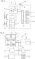
- a foot switch 1 according to the invention is shown schematically with a device 16 to be operated.
- the foot switch 1 comprises a housing 6 in which a first pedal 2 and a second pedal 3 are arranged, each with a tread 7.
- the tread has a grooved surface for better grip.
- the light from the LEDs 4 and 5 penetrates outwards through the respective viewing window 8 and is visible to a user.
- the pedals 2, 3 are operated in a known manner by a user with the foot in order to control the device 16.
- the pedals 2, 3 each have at least one actuation sensor 17 which is in Figure 1 is not shown.
- the sensor 17 detects the operation of the respective pedal 2, 3 by the user and forwards the signal to a microcontroller 19 in the foot switch 1. There the signal is processed by a processor not shown separately.
- the structure of the circuit of the various components within the foot switch 1 is shown in Figure 3 shown schematically.
- the actuation sensor 17 is, for example, a linear Hall sensor that measures magnetic field changes. This can, for example, precisely detect the movement of the tread 7 or the movement of a rotation axis of the pedal 2, 3.
- the foot switch 1 communicates with a connected device 16 and its control unit 12 (not shown here) via an interface 10 and a cable 9.
- This device 16 can be, for example, a medical suction pump that is used to remove unwanted liquids or gases from a body cavity.
- the user operates the foot switch 1 and activates or deactivates the suction function of the pump 16, for example if the view into the body cavity is impaired by liquid or gas.
- the control unit 17 is located inside the device 16 and is part of this device.
- the set strength of the suction function of the pump is displayed on a touch display 11.
- the function that the pedals 2, 3 of the foot switch 1 are to perform is communicated to the foot switch 1 by the control unit 12 via the interface 10.
- the foot switch 1 is designed to receive signals or commands from the control unit 12 via the interface 10. These are processed by a microcontroller 19 (see Figure 3 ).
- the activation of the pump is assigned to pedal 2 and the deactivation to pedal 3.
- the multi-colored LED 4 mounted above pedal 2 lights up in an orange tone, for example, while the LED 5 above pedal 3 lights up in a purple tone, for example.
- the RGB LEDs used here can light up in the various colors of the RGB color space. These colors are assigned to the functions and clearly tell the user which function is triggered by operating pedals 2 and 3 in device 16. In this way, incorrect operation of device 16 can be avoided.
- FIG. 2 shows a further embodiment of a foot switch 1.
- the components are as previously described, but the foot switch 1 and the control unit 12 of the device 16 are now in contact not via a cable, but via a wireless signal connection 13.
- the foot switch 1 and device 16 have transmitters and receivers not shown here.
- the foot switch 1 now also includes an actuation switch 14, which is arranged on the housing 6 of the foot switch 1.
- the switch 14 can also be operated with a foot and is, for example, a pressure switch. Actuating the switch 14 activates the foot switch 1 so that it is available.
- the actuation switch 14 is surrounded by a ring 15, behind which a multi-colored LED 22 is mounted.
- the ring 15 is transparent and can light up in different colors thanks to the LED 22.
- Different colors inform the user of the status of the foot switch 1, for example whether it is currently in contact with the device 16 and its control unit 12 via the wireless connection 13.
- the foot switch 1 can optionally be able to switch to a sleep mode after a long period of non-use. This sleep mode can also be indicated by a fixed color in the ring 15.
- the user can assign the functions assigned colors via the touch display 11 on the device 16. Since the multi-colored LEDs 4 and 5 are RGB LEDs, the colors of an RGB color space are available to the user and can be selected as required.
- the control unit 12 tells the foot switch 1 via the wireless connection 13 and the interface 10 which colors are to be assigned to the "Activate” and “Deactivate” functions and displayed on the pedals 2 and 3 by the LEDs 4 and 5.
- the microcontroller 19 in the foot switch 1 regulates the LEDs 4 and 5 accordingly (see also Figure 3 ).
- the circuit of the components within the foot switch 1 is shown schematically in the Figure 3 shown.
- the housing 6 of the foot switch 1 is indicated here by a dashed line.
- the pedals 2, 3 and the actuation switch 14 are also shown schematically on this housing.
- the pedals 2, 3 are each assigned an actuation sensor 17, which reports the actuation of the pedals to a microcontroller 19.
- a position sensor 18 detects when the foot switch 1 is no longer in a horizontal position, as is necessary for reliable operation of the foot switch 1, and causes the microcontroller 19 to deactivate the foot switch for safety reasons if necessary.
- the interface 10 with the antenna 20, which enables wireless communication with the device 16, is also connected to the microcontroller 19.
- the microcontroller 19 controls the RGB LEDs 4 and 5, as well as the third RGB LED 22, which is assigned to the ring 15 of the actuating switch 14, via the LED BUS 21 (I2C).
- the various colors of the RGB color space can be generated by appropriately controlling the intensities of the individual R, G and B diodes.
- the three diodes are each arranged in a common LED housing and electrically connected via a common input.
- the microcontroller 19 controls the LED 22 so that it lights up in a defined warning color and informs the user of the problem. It goes without saying that the actuation switch 14 and the third multi-colored LED 22 associated with it are optional. and need not be provided in other embodiments, as is the case, for example, Figure 1 was executed.
- FIG. 4 The special advantages of the foot switch 1 are also evident in Figure 4 .
- a medical system 24 is shown, with a foot switch 1 and a device 16 as previously described, as well as with a second device 27, a third device 28, a control unit 12 and a second foot switch 26.
- This foot switch 26 is according to the invention like the foot switch 1 from the embodiment of the Figure 1 designed, but it only has one pedal and a multi-colored LED for this pedal.
- the other components such as the housing, pedal, tread and internal structure are arranged in a similar way to the foot switch 26.
- the devices 16, 27 and 28 and the foot switches 1 and 26 are connected to one another via a medical data BUS 25.
- control unit 12 which in the present example is not arranged within the device 16 but forms a separate unit with its own housing.
- the control unit 12 here is an operating room controller that accesses all devices and foot switches in the system via the BUS 25 and controls the control of the devices via the foot switches.
- the control unit 12 assigns the various device functions of the devices 16, 27 and 28, which are to be controlled with the various pedals, to the foot switches 1 and 26 via their interfaces and the BUS 25.
- the control unit 12 assigns the required functions the colors that are to be displayed on the foot switches 1 and 26 associated with the pedals.
- the control unit 12 can assign individual colors to the functions either automatically or manually via the user, which make the functions and pedals distinguishable from one another and clearly indicate which pedal controls which function of the devices 16, 27 and 28. If required, the colors and functions can be reassigned to the foot switches 1 and 26 and their pedals. Alternatively, the control unit 12 can make the assignment immediately when the foot switches 1 and 26 are connected to the BUS 25 and the system 24.
- the system 24 can be expanded as desired and a large number of different functions can be assigned to the foot switches 1 and 26, as provided by the invention, which are identified by different colors, displayed on the foot switches and can be distinguished from one another.
Landscapes
- Health & Medical Sciences (AREA)
- Surgery (AREA)
- Life Sciences & Earth Sciences (AREA)
- Heart & Thoracic Surgery (AREA)
- Engineering & Computer Science (AREA)
- Biomedical Technology (AREA)
- Nuclear Medicine, Radiotherapy & Molecular Imaging (AREA)
- Medical Informatics (AREA)
- Molecular Biology (AREA)
- Animal Behavior & Ethology (AREA)
- General Health & Medical Sciences (AREA)
- Public Health (AREA)
- Veterinary Medicine (AREA)
- Pathology (AREA)
- Oral & Maxillofacial Surgery (AREA)
- Push-Button Switches (AREA)
Description
- Die vorliegende Erfindung ist auf einen Fußschalter zur Steuerung von einem oder mehreren medizinischen Geräten bezogen.
- Zahlreiche medizinische Geräte weisen Funktionen auf, die durch medizinisches Personal ausgelöst, an- und ausgeschaltet, verändert, moduliert oder auf andere Weise gesteuert werden können. Dazu sind an medizinischen Geräten Benutzerschnittstellen vorgesehen oder die medizinischen Geräte mit Benutzerschnittstellen koppelbar. Für viele Anwendungen sind Fußschalter üblich, um medizinischem Personal eine Steuerung von einer oder mehreren Funktionen auch dann zu ermöglichen, wenn keine Hand für eine manuelle Einwirkung auf eine Benutzerschnittstelle frei ist.
- Aus dem Stand der Technik ist bekannt, die Pedale medizinischer Fußschalter einzufärben, ihnen also feste Farben zuzuordnen, die die Funktion des Pedals anzeigen. So ist es üblich, mit Hochfrequenzchirurgie-Geräten verbundene Fußschalter mit blauen und gelben Pedalen zu versehen. Die Farben der Pedale lassen sich nicht ändern.
- Aus der
US7,557,317B2 ist ein medizinischer Fußschalter bekannt. Dieser kann mit einem elektrochirurgischen Gerät verbunden sein. Das Gehäuse des Fußschalters kann ein oder mehrere Lichtquellen aufweisen, die die am Gehäuse befestigten Pedale des Fußschalters beleuchten. Die Pedale weisen LEDs (Leuchtdioden) auf, die eine Funktion des betreffenden Pedals anzeigen. Die einzelnen LEDs können unterschiedlicher Farbe sein, einen Schriftzug von hinten beleuchten oder diesen Schriftzug bilden. Ebenfalls kann eine ausgewählte Funktion des Geräts auf einem Display am Fußschalter angezeigt werden. - Aus der
US 2010/198200 A1 ist ein medizinischer Fußschalter bekannt, der über mehrere LED zur Anzeige eines Status eines verbundenen medizinischen Geräts oder des Fußschalters selbst verfügt. In verschiedenen Ausführungsformen kann das Gerät (z. B. ein chirurgischer Fußschalter, ein Handstück usw.) und eine chirurgische Konsole von einem Bediener während eines chirurgischen Eingriffs (z. B. eines augenchirurgischen Eingriffs) und/oder in einem Verfahren (z. B. zur Untersuchung eines Patienten, zur Kalibrierung des Geräts usw.) verwendet werden. Das Gerät kann beispielsweise über eine Schnittstelle mit der chirurgischen Konsole kommunizieren, um Informationen im Zusammenhang mit dem Verfahren zu erhalten (z. B. Informationen über das Gerät, die Konsole oder andere bei dem Verfahren verwendete Ausrüstung). Weiter können die Informationen im Gerät ermittelt/erzeugt werden (d. h. sie müssen nicht unbedingt von der chirurgischen Konsole empfangen werden). Auf der Grundlage der Informationen kann eine Konfiguration (z. B. am Gerät, an der Konsole usw.) für eine oder mehrere Indikatoren am Gerät festgelegt werden, um dem Bediener des Geräts zumindest einen Teil der Informationen zu liefern. Es kann ein Steuersignal erzeugt werden, um den mindestens einen Indikator entsprechend der festgelegten Konfiguration zum Leuchten zu bringen. Der mindestens eine Indikator auf dem Gerät kann also entsprechend dem übermittelten Steuersignal aufleuchten, um dem Bediener zumindest einen Teil der mit dem Verfahren (z. B. chirurgisches Verfahren, Untersuchungsverfahren, Kalibrierung usw.) verbundenen Informationen zu liefern. - Aus der
US 5 635 777 A ist ein medizinischer Fußschalter bekannt, der mehrere Leuchten zur Anzeige von mehreren Funktionen eines verbundenen medizinischen Geräts verfügt, wobei jede Leuchte einer bestimmten Funktion zugeordnet ist. - Nachteilig an diesen aus dem Stand der Technik bekannten Fußschalter ist, dass nur eine sehr begrenzte Zahl von Funktionen durch die LEDs angezeigt und unterschieden werden kann. Andererseits ist das Vorsehen eines Displays zur Anzeige von Text auf dem Fußschalter sehr aufwändig und teuer.
- Es ist daher Aufgabe der vorliegenden Erfindung einen verbesserten Fußschalter zu schaffen, dem eine große Zahl verschiedener Funktionen zugeordnet werden kann.
- Diese Aufgabe wird durch ein erfindungsgemäßes medizinisches System mit einem Fußschalter und einem medizinischen Gerät gelöst, das in Anspruch 1 definiert ist.
- Vorteilhafte Weiterbildungen der Erfindung ergeben sich aus den Unteransprüchen.
- Der Fußschalter zur Verwendung mit einem medizinischen Gerät weist eine Schnittstelle zur kommunikativen Verbindung des Fußschalters mit einer Steuereinheit des Geräts auf. Über wenigstens ein Pedal des Fußschalters kann dieser von einem Anwender mit einem Fuß betätigt werden. Ein Betätigungssensor erfasst die Betätigung des Fußschalters, um so eine Funktion des medizinischen Geräts zu schalten. Der Betätigungssensor erzeugt hierfür ein entsprechendes, beispielsweise elektrisches, Signal, das über die Schnittstelle an die Steuereinheit des Geräts übertragen wird und dort das Schalten der Funktion des Geräts auslöst. Ferner weist der Fußschalter einen Prozessor auf, der dazu ausgebildet ist über die Schnittstelle Signale von der Steuereinheit zu empfangen, die dem wenigstens einen Pedal die zu schaltende Funktion zuordnen. Zudem ist an dem Fußschalter eine LED angeordnet, zur Anzeige der zugeordneten Funktion in einer bestimmten Farbe. Die LED ist hierbei eine mehrfarbige LED, die Licht in einer Vielzahl unterschiedlicher Farben erzeugen kann. Auf diese Weise werden die unterschiedlichen, dem Fußschalter jeweils zugeordneten Funktionen des Geräts in jeweils einer bestimmten Farbe durch die LED angezeigt.
- Der Fußschalter kann über ein, zwei oder mehrere Pedale verfügen, die das über die Schnittstelle verbundene Gerät oder einzelne Funktionen dieses Geräts steuern. Üblich sind beispielsweise Fußschalter mit zwei Pedalen. Das Pedal ist beispielsweise als Wippe ausgebildet, mit einer Trittfläche, über die der Anwender mit dem Fuß das Pedal betätigen kann. Die Betätigung des Pedals, d.h. die Bewegung der Trittfläche, wird über einen oder mehrere Sensoren erfasst. Beispielsweise haben sich hier Hall-Sensoren bewährt, insbesondere solche, die eine Magnetfeldänderung präzise erfassen können. Die Sensoren können mehrfach vorgesehen sein, um Signale miteinander abzugleichen und zur Sicherheit des Patienten Fehlfunktionen zu vermeiden. Fußschalter können Druckpunkte aufweisen, so dass bei der Betätigung des Pedals ein Widerstand überwunden werden muss, der dem Anwender ein besseres Gefühl für die Betätigung des Pedals gibt und ein versehentliches Betätigen vermeidet. Der Fußschalter kann über ein Kabel mit Strom versorgt werden oder auch über eine eigene Stromquelle wie eine Batterie verfügen.
- In der Medizin existiert eine Vielzahl von Geräten, die über Fußschalter gesteuert werden können, beispielsweise Pumpen für Flüssigkeiten, Insufflatoren zur Insufflation von Gas, Schlauchquetschventile, Kamerasysteme, Lichtquellen, Geräte zur Dokumentation von medizinischen Eingriffen, Geräte für die Hochfrequenzchirurgie, Steuergeräte für Laser, Motoren oder Lithotriptoren. Die zu steuernden Funktionen sind relevant für die Gesundheit des Patienten und potenziell gefährlich, so dass eine korrekte Bedienung der Geräte von großer Bedeutung ist.
- Fußschalter und Gerät bzw. dessen Steuereinheit können zur Kommunikation und zum Austausch von Signalen über Kabel oder auch drahtlos über die Schnittstelle am Fußschalter verbunden werden. Im Fall einer drahtlosen Verbindung wird die Steuereinheit bei der Kommunikation mit dem Fußschalter sicherstellen, dass der richtige Fußschalter angeschlossen ist und nur dieser das Gerät schalten darf. Auch wird der Fachmann Mittel vorsehen, um die korrekte Verbindung zwischen Gerät und Fußschalter zu überwachen. Bricht beispielsweise die drahtlose Verbindung ab, so kann die Funktion des Geräts sicherheitshalber abgeschaltet oder gestoppt werden.
- Erfindungsgemäß ist nun vorgesehen, dass die Steuereinheit des angeschlossenen Geräts dazu eingerichtet ist, dem Fußschalter für das wenigstens eine Pedal über die zur Kommunikation vorgesehene Schnittstelle eine Funktion des Geräts zuzuweisen, die über das Pedal gesteuert bzw. geschaltet werden soll. Die Signale werden hierfür über die Schnittstelle zum Prozessor des Fußschalters geleitet. Der Fußschalter ist also ein universell einsetzbarer Fußschalter, dem vorab keine feste Funktion zugewiesen ist, sondern dem je nach Anwendungsfall und Gerät vom angeschlossenen Gerät eine Funktion zugeordnet wird. Dies kann beim Anschluss des Fußschalters an das Gerät automatisch durch die Steuereinheit des Geräts erfolgen. Alternativ kann einem bereits angeschlossenen Fußschalter von einem Anwender über eine Bedieneinheit am Gerät oder der Steuereinheit eine oder mehrere Funktionen für die ein oder mehreren Pedale zugewiesen werden. Wiederum alternativ kann die Steuereinheit beim Einstellen eines bestimmten Betriebsmodus für das Gerät dem Fußschalter bzw. dessen Pedal eine dafür vorprogrammierte Funktion zuweisen. Allgemein kann die Steuereinheit Teil des medizinischen Geräts sein, sie kann jedoch auch eine separate Einheit sein, die beispielsweise auch noch weitere Geräte in einem medizinischen System steuert. Zur Kommunikation und zur Steuerung des Fußschalters selbst kann dieser einen Mikrocontroller aufweisen. Der Prozessor kann Teil des Mikrocontrollers sein, wie dies bei Mikrocontrollern üblicherweise vorgesehen ist. Das Gerät und die Steuereinheit können in bekannter Weise Prozessoren, Speicher, Software und Bedieneinheiten wie Schalter, Touchdisplays oder andere Eingabemittel aufweisen.
- Die Betätigung des Pedals am Fußschalter durch den Anwender führt zu einem vom Betätigungssensor ausgelösten Bediensignal, das über die Schnittstelle an die Steuereinheit des Geräts übermittelt wird und dort die zuvor zugewiesene Funktion auslöst oder beendet. Mit dem Begriff "schalten" ist im vorliegenden Text sowohl das Auslösen als auch das Beenden einer Funktion oder das Wechseln zu einer anderen Funktion gemeint.
- Da jedem Pedal des Fußschalters von der Steuereinheit eine Funktion individuell zugewiesen werden kann, ist vorgesehen, dass dem Anwender die zugewiesene Funktion durch eine farbig leuchtende LED (Light Emitting Diode, Leuchtdiode) am Fußschalter angezeigt wird. Es wird eine mehrfarbige LED verwendet, die in vielen unterschiedlichen Farben leuchten kann. So kann die mehrfarbige LED je nach Funktion des Geräts in einer bestimmten Farbe leuchten und dem Anwender die dem Pedal zugewiesene Funktion mitteilen. Es kann also jede Funktion durch eine eigene Farbe dargestellt werden, obwohl nur eine LED verwendet wird. Viele verschiedene Funktionen des Geräts oder mehrerer verbundener Geräte können dem Fußschalter bzw. den einzelnen Pedalen abwechselnd zugewiesen und jeweils durch eine eigene Farbe durch die mehrfarbige LED angezeigt werden. Dabei kann es sich um vorgegebene Farben handeln, die den gewünschten Funktionen üblicherweise zugeordnet werden oder durch eine Norm vorgeschrieben sind, wie Blau und Gelb für die Verwendung von Fußschaltern in der Hochfrequenzchirurgie für die Funktionen Koagulieren und Schneiden. Es kann sich jedoch auch um eine individuell vom Nutzer ausgewählte Farbe handeln, die dieser der speziellen gewünschten Funktion an der Steuereinheit manuell zuordnet. Bei mehreren Funktionen wird der Anwender verschiedene Farben auswählen. Alternativ sind geräteseitig bereits Farben für die unterschiedlichen Funktionen vorprogrammiert und werden dem Fußschalter mitgeteilt.
- Die mehrfarbige LED kann aus mehreren, insbesondere wenigstens zwei Leuchtdioden bestehen oder es kann sich um eine einzige Leuchtdiode handeln. Die Leuchtdioden können in einem gemeinsamen LED-Gehäuse angeordnet sein. Die Leuchtdioden der mehrfarbigen LED können über eine gemeinsame Kathode oder eine gemeinsame Anode verbunden sein. Alternativ kann die mehrfarbige LED nur zwei verschiedene Dioden umfassen.
- Die mehrfarbige LED kann insbesondere alle Farben eines RGB-Farbraums wiedergeben. Hierfür kann die mehrfarbige LED eine RGB-LED sein, also eine LED, die aus drei einzelnen Leuchtdioden besteht, die mit einstellbarer Intensität in den Farben Rot, Grün und Blau leuchten und zusammen alle Farben eines RGB-Farbraums erzeugen können. Die drei einzelnen Leuchtdioden werden dafür mit unterschiedlicher Intensität betrieben und kombiniert. Dem menschlichen Betrachter erscheint das Licht wie eine Farbe, die aus den drei Grundfarben gemischt wurde. Die mehrfarbige LED und insbesondere die RGB-LED hat den Vorteil, dass eine große Vielzahl von Funktionen unterschieden werden kann und diesen Funktionen individuelle Farben zugeordnet werden können, die dann nach der Zuordnung am Fußschalter angezeigt werden. Damit ist der Fußschalter für jede denkbare Anwendung geeignet und kann individuell verwendet werden.
- Auch in einem komplexen medizinischen System mit vielen Geräten und Funktionen, die über den Fußschalter gesteuert werden sollen, lassen sich die Pedale so eindeutig einer Funktion zuordnen. So kann der Fußschalter wenigstens zwei Pedale und zwei mehrfarbige LEDs aufweisen, wobei den Pedalen von der Steuereinheit unterschiedliche Funktionen zugewiesen werden. Diese Funktionen werden dann über die jeweilige mehrfarbige LED farbig angezeigt. Üblicherweise wird jedem Pedal eine eigene mehrfarbige LED zugeordnet sein.
- Der Anwender sieht auf einen Blick, welche Funktion einem Pedal zugeordnet ist und eine Fehlbedienung wird vermieden. Auch kann der Fußschalter insbesondere bei einer drahtlosen Verbindung im Wechsel mit unterschiedlichen Geräten verbunden werden, die den Pedalen die jeweils passende Funktion zuordnen und diese am Fußschalter mit der entsprechenden Farbe anzeigen lassen. Dies erhöht die Flexibilität des Systems und der Anwendung. Auch benötigt man nicht mehr einen Fußschalter für jede Funktion.
- Der Fußschalter kann ein Gehäuse aufweisen, in oder an dem das eine oder die mehreren Pedale angeordnet sind. In diesem Fall kann sich die mehrfarbige LED im Gehäuse befinden und mit einem transparenten Sichtfenster abgedeckt sein, durch welches ein Anwender die von der mehrfarbigen LED erzeugte Lichtfarbe sehen kann. Das Sichtfenster kann in der Oberfläche des Gehäuses angeordnet sein und beispielsweise bündig mit diesem abschließen. Beispielsweise kann sich die mehrfarbige LED in einem Bereich des Gehäuses oberhalb des Pedals befinden. Das Sichtfenster ist dann in der Oberseite des Gehäuses angeordnet. Auch andere Abdeckungen der LEDs sind denkbar. Ebenso können sich diese statt im Gehäuse in der Trittfläche des Pedals befinden. Dies hat jedoch den Nachteil, dass das farbige Licht bei Betätigung durch den Fuß möglicherweise nicht mehr zu sehen ist.
- Das Gehäuse des Fußschalters kann weiterhin einen zusätzlichen Betätigungsschalter aufweisen, über den sich weitere Funktionen schalten lassen. Beispielsweise könnte damit der Fußschalter aktiviert und deaktiviert oder die drahtlose Verbindung aktiviert oder deaktiviert werden. Der Schalter kann ebenfalls durch eine insbesondere mehrfarbige LED beleuchtet werden, die den Schalter selbst erleuchtet, oder der Schalter kann einen Rand aufweisen, beispielsweise einen Ring, der den Schalter umgibt, der von einer LED erleuchtet wird. So lassen sich der Aktivierungszustand des Fußschalters oder der drahtlosen Verbindung oder auch Fehlermeldungen durch verschiedene Farben oder Signale wie Blinken darstellen, um den Anwender zu informieren.
- Zur Kommunikation zwischen Fußschalter und Gerät bzw. dessen Steuereinheit können beide Teile über ein medizinisches Datenübertragungssystem, insbesondere ein BUSSystem verbunden sein. Dieses kann wiederum Teil eines größeren medizinischen Systems mit vielen Komponenten sein, wie dies in einem Operationssaal der Fall ist. Die Steuereinheit kann dann auch Teil der Steuerung des Operationssaales sein. Es kann vorgesehen sein, dass der Fußschalter bei Aktivierung oder Verbindung mit dem System automatisch erkannt wird und ihm bereits vorausgewählte Funktionen von der Steuereinheit zugewiesen werden, die dann durch die mehrfarbigen LEDs angezeigt werden.
- Alternativ können ein Gerät mit Steuereinheit und ein Fußschalter über andere kabelgebundene oder drahtlose Signalwege miteinander verbunden sein und die Steuereinheit kann über einen BUS oder eine andere Datenverbindung mit einem medizinischen System verbunden sein.
- Die Erfindung umfasst daher auch ein medizinisches System mit wenigstens zwei Geräten und wenigstens einem vorstehend beschriebenen Fußschalter, wobei die Geräte und der wenigstens eine Fußschalter über ein medizinisches Datenübertragungssystem verbunden sind und über dieses kommunizieren.
- Weitere Aspekte der Erfindung ergeben sich aus der nachfolgenden Beschreibung der bevorzugten Ausführungsbeispiele und den beigefügten Zeichnungen. Es zeigen:
- Figur 1
- einen Fußschalter in Verbindung mit einem Gerät
- Figur 2
- einen Fußschalter in drahtloser Verbindung mit einem Gerät
- Figur 3
- eine schematische Darstellung des Fußschalters
- Figur 4
- ein medizinisches System mit Geräten und Fußschaltern
- In
Figur 1 ist schematisch ein erfindungsgemäßer Fußschalter 1 mit zu bedienendem Gerät 16 dargestellt. Der Fußschalter 1 umfasst ein Gehäuse 6, in dem ein erstes Pedal 2 und ein zweites Pedal 3 jeweils mit einer Trittfläche 7 angeordnet sind. Die Trittfläche hat eine geriffelte Oberfläche für besseren Halt. In einem Bereich des Gehäuses 6 oberhalb der Pedale 2 und 3 befinden sich Sichtfenster 8, hinter denen sich eine erste mehrfarbige LED 4 und eine zweite mehrfarbige LED 5 befinden. Das Licht der LEDs 4 und 5 dringt durch das jeweilige Sichtfenster 8 nach außen und ist für einen Anwender erkennbar. Die Pedale 2, 3 werden in bekannter Weise von einem Anwender mit dem Fuß bedient, um das Gerät 16 zu steuern. Zu diesem Zweck weisen die Pedale 2, 3 jeweils wenigstens einen Betätigungssensor 17 auf, der inFigur 1 nicht dargestellt ist. Der Sensor 17 erfasst die Betätigung des jeweiligen Pedals 2, 3 durch den Anwender und leitet das Signal an einen Mikrocontroller 19 im Fußschalter 1 weiter. Dort wird das Signal von einem nicht gesondert dargestellten Prozessor verarbeitet. Der Aufbau der Schaltung der verschiedenen Komponenten innerhalb des Fußschalters 1 ist inFigur 3 schematisch dargestellt. Der Betätigungssensor 17 ist beispielsweise ein linearer Hall-Sensor der Magnetfeldänderungen misst. Dieser kann beispielsweise die Bewegung der Trittfläche 7 oder die Bewegung einer Drehachse des Pedals 2, 3 präzise erfassen. - Über eine Schnittstelle 10 und ein Kabel 9 kommuniziert der Fußschalter 1 mit einem verbundenen Gerät 16 und dessen Steuereinheit 12 (hier nicht dargestellt). Dieses Gerät 16 kann beispielsweise eine medizinische Saugpumpe sein, die der Entfernung von unerwünschten Flüssigkeiten oder Gasen aus einer Körperhöhle dient. Der Anwender betätigt den Fußschalter 1 und aktiviert oder deaktiviert die Saugfunktion der Pumpe 16, beispielsweise wenn die Sicht in die Körperhöhle durch Flüssigkeit oder Gas beeinträchtigt ist. Die Steuereinheit 17 befindet sich in diesem Beispiel innerhalb des Geräts 16 und ist Teil dieses Geräts. Auf einem Touchdisplay 11 wird die eingestellte Stärke der Saugfunktion der Pumpe angezeigt.
- Welche Funktion die Pedale 2, 3 des Fußschalters 1 ausführen sollen, wird dem Fußschalter 1 von der Steuereinheit 12 über die Schnittstelle 10 mitgeteilt. Der Fußschalter 1 ist hierfür eingerichtet, von der Steuereinheit 12 Signale oder Befehle über die Schnittstelle 10 zu empfangen. Diese werden von einem Mikrocontroller 19 verarbeitet (s.
Figur 3 ). - Im vorliegenden Beispiel sei die Aktivierung der Pumpe dem Pedal 2 und die Deaktivierung dem Pedal 3 zugeordnet. Die oberhalb des Pedals 2 angebrachte mehrfarbige LED 4 leuchtet beispielsweise in einem Orangeton, die LED 5 oberhalb des Pedals 3 beispielsweise in einem Lilaton. Die hier verwendeten RGB-LEDs können in den verschiedenen Farben des RGB-Farbraums leuchten. Diese Farben sind den Funktionen zugeordnet und teilen dem Anwender eindeutig mit, welche Funktion durch die Bedienung der Pedale 2 und 3 im Gerät 16 ausgelöst wird. Auf diese Weise kann eine Fehlbedienung des Gerätes 16 vermieden werden.
-
Figur 2 zeigt ein weiteres Ausführungsbeispiel eines Fußschalters 1. Die Komponenten sind wie zuvor beschrieben, jedoch sind der Fußschalter 1 und die Steuereinheit 12 des Geräts 16 nun nicht über ein Kabel, sondern über eine drahtlose Signalverbindung 13 in Kontakt. Zu diesem Zweck weisen Fußschalter 1 und Gerät 16 hier nicht dargestellte Sender und Empfänger auf. Der Fußschalter 1 umfasst nun zusätzlich einen Betätigungsschalter 14, der auf dem Gehäuse 6 des Fußschalters 1 angeordnet ist. Der Schalter 14 kann ebenfalls mit einem Fuß bedient werden und ist beispielsweise ein Druckschalter. Betätigen des Schalters 14 aktiviert den Fußschalter 1, so dass dieser zur Verfügung steht. Der Betätigungsschalter 14 ist von einem Ring 15 umgeben, hinter dem wiederum eine mehrfarbige LED 22 angebracht ist. Der Ring 15 ist transparent und kann dank der LED 22 in verschiedenen Farben leuchten. Durch unterschiedliche Farben wird dem Anwender der Status des Fußschalters 1 mitgeteilt, beispielsweise ob dieser aktuell über die drahtlose Verbindung 13 mit dem Gerät 16 und dessen Steuereinheit 12 in Kontakt steht. Der Fußschalter 1 kann optional in der Lage sein, nach längerem Nichtgebrauch in einen Ruhemodus zu schalten. Dieser Ruhemodus kann ebenfalls über eine festgelegte Farbe im Ring 15 angezeigt werden. - Wenn der Anwender dem Fußschalter 1 und dessen Pedalen 2 und 3 nun andere Farben für die Funktionen "Aktivieren" und "Deaktivieren" zuordnen möchte, beispielsweise um sie deutlicher von den Farben eines anderen Fußschalters zu unterscheiden oder weil Farben einem Anwender besser erkennbar erscheinen, kann der Anwender die den Funktionen zugeordneten Farben über das Touchdisplay 11 am Gerät 16 ändern. Da es sich bei den mehrfarbigen LEDs 4 und 5 um RGB-LEDs handelt, stehen dem Anwender die Farben eines RGB-Farbraums zur Verfügung und können nach Bedarf gewählt werden. Nach der Auswahl teilt die Steuereinheit 12 dem Fußschalter 1 über die Wireless-Verbindung 13 und die Schnittstelle 10 mit, welche Farben den Funktionen "Aktivieren" und "Deaktivieren" zugeordnet und bei den Pedalen 2 und 3 durch die LEDs 4 und 5 angezeigt werden sollen. Der Mikrocontroller 19 im Fußschalter 1 regelt die LEDs 4 und 5 entsprechend (s. auch
Figur 3 ). - Die Schaltung der Komponenten innerhalb des Fußschalters 1 ist schematisch in der
Figur 3 dargestellt. Das Gehäuse 6 des Fußschalters 1 ist hier durch eine gestrichelte Linie angedeutet. Schematisch sind an diesem Gehäuse auch die Pedale 2, 3 und der Betätigungsschalter 14 dargestellt. Den Pedalen 2, 3 ist jeweils ein Betätigungssensor 17 zugeordnet, der die Betätigung der Pedale an einen Mikrocontroller 19 meldet. Ein Lagesensor 18 erfasst, wenn sich der Fußschalter 1 nicht mehr in einer waagerechten Position befindet, so wie sie für eine zuverlässige Bedienung des Fußschalters 1 notwendig ist, und veranlasst den Mikrocontroller 19 gegebenenfalls den Fußschalter sicherheitshalber zu deaktivieren. Mit dem Mikrocontroller 19 steht auch die Schnittstelle 10 mit der Antenne 20 in Verbindung, die die drahtlose Kommunikation mit dem Gerät 16 ermöglicht. In Abhängigkeit der Anweisungen der Steuereinheit 12 des Geräts 16 steuert der Mikrocontroller 19 über den LED-BUS 21 (I2C) die RGB-LEDs 4 und 5, sowie die dritte RGB-LED 22, die dem Ring 15 des Betätigungsschalters 14 zugeordnet ist. Durch geeignetes Steuern der Intensitäten der einzelnen R-, G- und B-Dioden lassen sich die verschiedenen Farben des RGB-Farbraums erzeugen. Die drei Dioden sind jeweils in einem gemeinsamen LED-Gehäuse angeordnet und über einen gemeinsamen Eingang elektrisch verbunden. - Tritt bei der drahtlosen Verbindung 13 beispielsweise eine Störung auf, so dass eine sichere Kommunikation zwischen Fußschalter 1 und Gerät 16 nicht mehr gewährleistet ist, so steuert der Mikrocontroller 19 die LED 22 derart, dass sie in einer definierten Warnfarbe leuchtet und den Anwender über das Problem informiert. Es versteht sich, dass der Betätigungsschalter 14 und die ihm zugeordnete dritte mehrfarbige LED 22 optional sind und in anderen Ausführungsformen nicht vorgesehen sein müssen, wie dies beispielsweise zu
Figur 1 ausgeführt wurde. - Die besonderen Vorteile des Fußschalters 1 zeigen sich auch in
Figur 4 . Hier ist ein medizinisches System 24 dargestellt, mit einem Fußschalter 1 und einem Gerät 16 wie zuvor beschrieben, sowie mit einem zweiten Gerät 27, einem dritten Gerät 28, einer Steuereinheit 12 und einem zweiten Fußschalter 26. Dieser Fußschalter 26 ist erfindungsgemäß wie der Fußschalter 1 aus dem Ausführungsbeispiel derFigur 1 gestaltet, jedoch weist er nur ein Pedal und eine mehrfarbige LED für dieses Pedal auf. Die anderen Komponenten wie Gehäuse, Pedal, Trittfläche und innerer Aufbau sind analog dem Fußschalter 26 angeordnet. Die Geräte 16, 27 und 28 und die Fußschalter 1 und 26 sind über einen medizinischen Daten-BUS 25 untereinander verbunden. Ebenfalls Teil dieses Systems 24 und mit dem BUS 25 verbunden ist die Steuereinheit 12, die im vorliegenden Beispiel nicht innerhalb des Geräts 16 angeordnet ist, sondern eine separate Einheit mit eigenem Gehäuse bildet. Die Steuereinheit 12 ist hier eine Operationssaal-Steuerung, die über den BUS 25 auf alle Geräte und Fußschalter im System zugreift und die Steuerung der Geräte über die Fußschalter steuert. Insbesondere weist die Steuereinheit 12 den Fußschaltern 1 und 26 über deren Schnittstellen und den BUS 25 die verschiedenen Gerätefunktionen der Geräte 16, 27 und 28 zu, die mit den verschiedenen Pedalen gesteuert werden sollen. Außerdem weist die Steuereinheit 12 den benötigten Funktionen die Farben zu, die an den Fußschaltern 1 und 26 den Pedalen zugeordnet angezeigt werden sollen. Die Steuereinheit 12 kann hier automatisch oder manuell über den Anwender den Funktionen individuelle Farben zuordnen, die die Funktionen und Pedale voneinander unterscheidbar machen und eindeutig anzeigen, welches Pedal welche Funktion der Geräte 16, 27 und 28 steuert. Nach Bedarf können die Farben und Funktionen den Fußschaltern 1 und 26 und deren Pedalen neu zugeordnet werden. Alternativ kann die Steuereinheit 12 die Zuordnung sofort vornehmen, wenn die Fußschalter 1 und 26 mit dem BUS 25 und dem System 24 verbunden werden. Das System 24 lässt sich beliebig erweitern und den Fußschaltern 1 und 26 wie erfindungsgemäß vorgesehen eine große Zahl verschiedener Funktionen zuordnen, die durch unterschiedliche Farben gekennzeichnet, an den Fußschaltern angezeigt und voneinander unterschieden werden können. -
- 1
- Fußschalter
- 2
- erstes Pedal
- 3
- zweites Pedal
- 4
- erste mehrfarbige LED
- 5
- zweite mehrfarbige LED
- 6
- Gehäuse
- 7
- Trittfläche
- 8
- Sichtfenster
- 9
- Kabel
- 10
- Schnittstelle
- 11
- Touchdisplay
- 12
- Steuereinheit
- 13
- Wireless-Verbindung
- 14
- Betätigungsschalter
- 15
- Ring
- 16
- Gerät
- 17
- Betätigungssensor
- 18
- Lagesensor
- 19
- Mikrocontroller
- 20
- Antenne
- 21
- LED-BUS
- 22
- dritte mehrfarbige LED
- 24
- medizinisches System
- 25
- BUS
- 26
- zweiter Fußschalter
- 27
- zweites Gerät
- 28
- drittes Gerät
Claims (11)
- Medizinisches System (24) mit einem medizinischen Gerät (16, 27, 28) und mit einem Fußschalter (1, 26) zur Verwendung mit dem medizinischen Gerät (16, 27, 28),
der Fußschalter (1, 26) umfassend:eine Schnittstelle (10) zur kommunikativen Verbindung des Fußschalters (1, 26) mit einer Steuereinheit (12) des Geräts (16, 27, 28),wenigstens ein Pedal (2, 3) zur Betätigung des Fußschalters (1, 26) mit einem Fuß,einen Betätigungssensor (17), der dazu ausgebildet ist eine Betätigung des Fußschalters (1, 26) zu erfassen,wobei der Betätigungssensor (17) ein Signal erzeugt, das über die Schnittstelle (10) an die Steuereinheit (12) des Geräts (16, 27, 28) übertragen wird, zum Schalten einer Funktion des medizinischen Geräts (16, 27, 28),einen Prozessor, der dazu ausgebildet ist über die Schnittstelle (10) Signale von der Steuereinheit (12) zu empfangen, die dem wenigstens einen Pedal (2, 3) die zu schaltende Funktion zuordnen, undwenigstens eine LED, zur Anzeige der zugeordneten Funktion in einer bestimmten Farbe,wobei die LED eine mehrfarbige LED (4, 5) ist, die Licht in einer Vielzahl unterschiedlicher Farben erzeugen kann, zur Anzeige unterschiedlicher Funktionen des Geräts (16, 27, 28). - Medizinisches System (24) nach Anspruch 1,
wobei die mehrfarbige LED (4, 5) wenigstens zwei Leuchtdioden umfasst, die eine gemeinsame Anode oder eine gemeinsame Kathode aufweisen. - Medizinisches System (24) nach einem der vorherigen Ansprüche,
wobei die mehrfarbige LED (4, 5) wenigstens zwei Leuchtdioden umfasst, die in einem gemeinsamen LED-Gehäuse angeordnet sind. - Medizinisches System (24) nach einem der vorherigen Ansprüche, wobei die mehrfarbige LED (4, 5) alle Farben eines RGB-Farbraums wiedergeben kann.
- Medizinisches System (24) nach einem der vorherigen Ansprüche,
wobei der Fußschalter (1, 26) ein Gehäuse (6) aufweist, an dem das wenigstens eine Pedal (2, 3) und die wenigstens eine mehrfarbige LED (4, 5) angeordnet sind. - Medizinisches System (24) nach einem der vorherigen Ansprüche,
wobei der Fußschalter (1, 26) wenigstens zwei Pedale (2, 3) und wenigstens zwei mehrfarbige LEDs (4, 5) aufweist und den Pedalen (2, 3) von der Steuereinheit (12) des Geräts (16, 27, 28) unterschiedliche Funktionen zugeordnet werden können und die zugeordneten Funktionen jeweils durch eine der mehrfarbigen LEDs (4, 5) angezeigt werden. - Medizinisches System (24) nach einem der vorherigen Ansprüche,
wobei die mehrfarbige LED (4, 5) jeweils durch ein transparentes Sichtfenster (8) abgedeckt ist, durch welches ein Anwender die von der mehrfarbigen LED (4, 5) erzeugte Lichtfarbe sehen kann. - Medizinisches System (24) nach Anspruch 7,
wobei das Sichtfenster (8) in einer Fläche des Gehäuses (6) angeordnet ist. - Medizinisches System (24) nach einem der Ansprüche 5 bis 8,
wobei das Gehäuse (6) zusätzlich einen Betätigungsschalter (14) aufweist, der durch eine weitere Leuchtdiode (22) beleuchtet wird oder von einem von einer weiteren Leuchtdiode (22) beleuchteten Rand (15) umgeben ist. - Medizinisches System (24) nach einem der vorherigen Ansprüche,
wobei der Fußschalter (1, 26) und das Gerät (16, 27, 28) über ein medizinisches Datenübertragungssystem (25) verbunden sind und über dieses kommunizieren. - Medizinisches System (24) nach einem der vorherigen Ansprüche mit wenigstens einem weiteren Gerät (16; 27, 28),
wobei die Geräte (16, 27, 28) und der Fußschalter (1, 26) über ein medizinisches Datenübertragungssystem (25) verbunden sind und über dieses kommunizieren.
Applications Claiming Priority (1)
| Application Number | Priority Date | Filing Date | Title |
|---|---|---|---|
| DE102019125490.6A DE102019125490A1 (de) | 2019-09-23 | 2019-09-23 | Fußschalter für medizinische Geräte |
Publications (2)
| Publication Number | Publication Date |
|---|---|
| EP3796356A1 EP3796356A1 (de) | 2021-03-24 |
| EP3796356B1 true EP3796356B1 (de) | 2024-05-29 |
Family
ID=72658952
Family Applications (1)
| Application Number | Title | Priority Date | Filing Date |
|---|---|---|---|
| EP20197773.3A Active EP3796356B1 (de) | 2019-09-23 | 2020-09-23 | Fussschalter für medizinische geräte |
Country Status (3)
| Country | Link |
|---|---|
| US (1) | US11759187B2 (de) |
| EP (1) | EP3796356B1 (de) |
| DE (1) | DE102019125490A1 (de) |
Families Citing this family (2)
| Publication number | Priority date | Publication date | Assignee | Title |
|---|---|---|---|---|
| US12081457B2 (en) * | 2020-10-29 | 2024-09-03 | Sigma Defense Systems Llc | Apparatus and method for selecting and providing network equipment security designations |
| EP4559425A1 (de) * | 2023-11-27 | 2025-05-28 | Smith & Nephew, Inc. | Systeme zur punkt- und werkzeugaktivierung |
Family Cites Families (39)
| Publication number | Priority date | Publication date | Assignee | Title |
|---|---|---|---|---|
| US5883615A (en) * | 1995-09-29 | 1999-03-16 | Liebel-Flarsheim Company | Foot-operated control system for a multi-function |
| US5635777A (en) * | 1995-12-28 | 1997-06-03 | Andrew Telymonde | Foot operated control apparatus |
| US5758267A (en) * | 1996-07-08 | 1998-05-26 | Motorola, Inc. | Method and apparatus for orientation controlled parameter selection |
| US6618039B1 (en) * | 1996-09-12 | 2003-09-09 | Gerry R. Grant | Pocket-sized user interface for internet browser terminals and the like |
| US6666860B1 (en) * | 1999-08-24 | 2003-12-23 | Olympus Optical Co., Ltd. | Electric treatment system |
| DE10057589C1 (de) * | 2000-11-21 | 2002-07-11 | Erbe Elektromedizin | Fußschalter |
| WO2003105169A1 (en) * | 2002-06-11 | 2003-12-18 | Tyco Healthcare Group, Lp | Illuminated foot-switch |
| JP4129217B2 (ja) * | 2003-09-29 | 2008-08-06 | オリンパス株式会社 | 超音波手術システム、その異常検知方法および異常検知プログラム |
| JP5410648B2 (ja) * | 2004-08-26 | 2014-02-05 | 株式会社ピュアロンジャパン | 表示パネルおよび該表示パネルに用いる発光ユニット |
| JP2010524518A (ja) * | 2007-04-11 | 2010-07-22 | フォース フォトニクス リミテッド | 支持構造及び該支持構造を含む子宮の生体内検査を改良し、客観化し、文書化するワークステーション |
| EP2031531A3 (de) * | 2007-07-20 | 2009-04-29 | BrainLAB AG | Integriertes medizintechnisches Anzeigesystem |
| US20090046146A1 (en) * | 2007-08-13 | 2009-02-19 | Jonathan Hoyt | Surgical communication and control system |
| US20100198200A1 (en) * | 2009-01-30 | 2010-08-05 | Christopher Horvath | Smart Illumination for Surgical Devices |
| WO2011123669A1 (en) * | 2010-03-31 | 2011-10-06 | St. Jude Medical, Atrial Fibrillation Division, Inc. | Intuitive user interface control for remote catheter navigation and 3d mapping and visualization systems |
| USRE47996E1 (en) * | 2009-10-09 | 2020-05-19 | Ethicon Llc | Surgical generator for ultrasonic and electrosurgical devices |
| US9060775B2 (en) * | 2009-10-09 | 2015-06-23 | Ethicon Endo-Surgery, Inc. | Surgical generator for ultrasonic and electrosurgical devices |
| US8558716B2 (en) * | 2010-06-10 | 2013-10-15 | Verizon Patent And Licensing Inc. | Systems and methods to adaptively change functionality of a remote control device to execute the script on a client program for reprogramming buttons on the remote control device |
| JP5135404B2 (ja) * | 2010-09-30 | 2013-02-06 | 株式会社東芝 | 情報処理装置 |
| EP2765918A4 (de) * | 2011-10-10 | 2015-05-06 | Tractus Corp | Verfahren, vorrichtung und system zur vollständigen untersuchung von gewebeproben mit tragbaren bildgebungsvorrichtungen |
| TWI446900B (zh) * | 2012-01-10 | 2014-08-01 | Timotion Technology Co Ltd | 具有安全機制的腳控開關 |
| US9217561B2 (en) * | 2012-06-15 | 2015-12-22 | Lumencor, Inc. | Solid state light source for photocuring |
| AU2014253909B2 (en) * | 2013-04-19 | 2018-11-01 | Johnson & Johnson Surgical Vision, Inc. | Foot pedal system and apparatus |
| WO2015088014A1 (ja) * | 2013-12-13 | 2015-06-18 | オリンパス株式会社 | 処置具、処置具ユニット及び処置システム |
| EP2915502B1 (de) * | 2014-03-06 | 2019-11-20 | W & H Dentalwerk Bürmoos GmbH | Medizinisches, insbesondere zahnärztliches, System |
| US10021487B2 (en) * | 2014-09-19 | 2018-07-10 | Axent Wear Inc. | Headsets with external speakers with predetermined shapes and designs |
| GB2546944B (en) * | 2014-10-17 | 2020-05-27 | Synaptive Medical Barbados Inc | Head restraining apparatus for a medical procedure |
| US10639104B1 (en) * | 2014-11-07 | 2020-05-05 | Verily Life Sciences Llc | Surgery guidance system |
| US10144637B2 (en) * | 2014-11-25 | 2018-12-04 | Synaptive Medical (Barbados) Inc. | Sensor based tracking tool for medical components |
| EP3226799A4 (de) * | 2014-12-05 | 2018-07-25 | Camplex, Inc. | Chirurgische visualisierungssysteme und anzeigen |
| US9845739B2 (en) * | 2014-12-17 | 2017-12-19 | Textron Innovations Inc. | Systems and methods for automatically controlling the engine of a turf-care vehicle |
| US9925013B2 (en) * | 2016-01-14 | 2018-03-27 | Synaptive Medical (Barbados) Inc. | System and method for configuring positions in a surgical positioning system |
| DE102016209576B4 (de) * | 2016-06-01 | 2024-06-13 | Siemens Healthineers Ag | Bewegungssteuerung für ein mobiles Medizingerät |
| EP3651677B1 (de) * | 2017-07-13 | 2024-02-21 | Intuitive Surgical Operations, Inc. | Systeme und verfahren zur schaltsteuerung zwischen mehreren instrumentenarmen |
| US10898399B2 (en) * | 2017-12-20 | 2021-01-26 | Stryker Corporation | User controls for patient support apparatus having low height |
| US10888383B2 (en) * | 2018-07-17 | 2021-01-12 | Verb Surgical Inc. | Robotic surgical pedal with integrated foot sensor |
| US10503199B1 (en) * | 2018-07-17 | 2019-12-10 | Verb Surgical Inc. | Pedal with sliding and locking mechanisms for surgical robots |
| US11481957B2 (en) * | 2019-04-01 | 2022-10-25 | Canon Medical Systems Corporation | Medical image processing apparatus and storage medium |
| WO2020210621A1 (en) * | 2019-04-12 | 2020-10-15 | Mako Surgical Corp. | Robotic systems and methods for manipulating a cutting guide for a surgical instrument |
| US12402963B2 (en) * | 2019-07-31 | 2025-09-02 | Auris Health, Inc. | Apparatus, systems, and methods to facilitate instrument visualization |
-
2019
- 2019-09-23 DE DE102019125490.6A patent/DE102019125490A1/de active Pending
-
2020
- 2020-09-17 US US17/023,729 patent/US11759187B2/en active Active
- 2020-09-23 EP EP20197773.3A patent/EP3796356B1/de active Active
Also Published As
| Publication number | Publication date |
|---|---|
| US20210085299A1 (en) | 2021-03-25 |
| US11759187B2 (en) | 2023-09-19 |
| EP3796356A1 (de) | 2021-03-24 |
| DE102019125490A1 (de) | 2021-03-25 |
Similar Documents
| Publication | Publication Date | Title |
|---|---|---|
| WO2017025607A1 (de) | Medizinischer haltearm mit ringförmigen led-anzeigemitteln | |
| EP2207493A1 (de) | Signaleinrichtung für elektrochirurgische instrumente, adapter zum anschluss eines elektrochirurgischen instruments | |
| EP2455053A1 (de) | Tragesystem mit Bedienungshilfe | |
| EP1951004A2 (de) | Leuchtensteuerungssystem | |
| DE102014218493A1 (de) | Anzeige- und Bedienvorrichtung, insbesondere für ein Kraftfahrzeug, Bedienelement und Kraftfahrzeug | |
| DE102008035090A1 (de) | Flexibel einsetzbares Anzeige- und Bedienelementfeld zur Steuerung von Kabinenfunktionen | |
| WO2008113797A1 (de) | Leucht-schaltstellungsanzeige | |
| DE19945775A1 (de) | Leuchtenanordnung für ein Fahrzeug | |
| EP3796356A1 (de) | Fussschalter für medizinische geräte | |
| DE102015116175B4 (de) | System und Verfahren um eine visuelle Rückmeldung in einem Luftfahrzeug zur Verfügung zu stellen | |
| EP2437574A2 (de) | Bedienvorrichtung zur Ansteuerung einer mehrfarbigen Lichtquelle und Beleuchtungsvorrichtung | |
| EP2923540B1 (de) | Landwirtschaftliche Arbeitsmaschine | |
| EP2880673A1 (de) | Schaltvorrichtung mit funkmodul und deaktivierungsfunktion | |
| DE10138182A1 (de) | Anzeigenanordnung und Bedienelement für Kraftfahrzeuge | |
| DE102013219145B4 (de) | Medizinsystem | |
| EP2113931B1 (de) | Handbedienung zur Bedienung eines elektromotorischen Möbelantriebs | |
| DE69916654T2 (de) | Vorrichtung zum anzeigen vielfacher zustände | |
| DE102008041696A1 (de) | Farbsignalisierungslinse | |
| WO2004005065A1 (de) | Programmierbares bedienelement | |
| DE3522823A1 (de) | Bedienteil fuer eine elektrohydraulische hubwerksregeleinrichtung von traktoren | |
| EP3127098A1 (de) | Mit einer drahtlosen schnittstelle ausgestattete anzeigevorrichtung für den betriebszustand einer schaltvorrichtung | |
| AT501609B1 (de) | Handsteller für eine beleuchtungs-mischlichtquelle | |
| DE202016105335U1 (de) | Lichtquellencontroller | |
| WO2014183862A2 (de) | Medizinisches gerät | |
| DE102025138499A1 (de) | Fahrzeug mit einer Anzeigeeinheit zum Anzeigen eines Öffnungswinkels eines Kofferraumdeckels |
Legal Events
| Date | Code | Title | Description |
|---|---|---|---|
| PUAI | Public reference made under article 153(3) epc to a published international application that has entered the european phase |
Free format text: ORIGINAL CODE: 0009012 |
|
| STAA | Information on the status of an ep patent application or granted ep patent |
Free format text: STATUS: THE APPLICATION HAS BEEN PUBLISHED |
|
| AK | Designated contracting states |
Kind code of ref document: A1 Designated state(s): AL AT BE BG CH CY CZ DE DK EE ES FI FR GB GR HR HU IE IS IT LI LT LU LV MC MK MT NL NO PL PT RO RS SE SI SK SM TR |
|
| AX | Request for extension of the european patent |
Extension state: BA ME |
|
| STAA | Information on the status of an ep patent application or granted ep patent |
Free format text: STATUS: REQUEST FOR EXAMINATION WAS MADE |
|
| 17P | Request for examination filed |
Effective date: 20210901 |
|
| RBV | Designated contracting states (corrected) |
Designated state(s): AL AT BE BG CH CY CZ DE DK EE ES FI FR GB GR HR HU IE IS IT LI LT LU LV MC MK MT NL NO PL PT RO RS SE SI SK SM TR |
|
| STAA | Information on the status of an ep patent application or granted ep patent |
Free format text: STATUS: EXAMINATION IS IN PROGRESS |
|
| 17Q | First examination report despatched |
Effective date: 20220608 |
|
| P01 | Opt-out of the competence of the unified patent court (upc) registered |
Effective date: 20230527 |
|
| GRAP | Despatch of communication of intention to grant a patent |
Free format text: ORIGINAL CODE: EPIDOSNIGR1 |
|
| STAA | Information on the status of an ep patent application or granted ep patent |
Free format text: STATUS: GRANT OF PATENT IS INTENDED |
|
| INTG | Intention to grant announced |
Effective date: 20240104 |
|
| GRAS | Grant fee paid |
Free format text: ORIGINAL CODE: EPIDOSNIGR3 |
|
| GRAA | (expected) grant |
Free format text: ORIGINAL CODE: 0009210 |
|
| STAA | Information on the status of an ep patent application or granted ep patent |
Free format text: STATUS: THE PATENT HAS BEEN GRANTED |
|
| AK | Designated contracting states |
Kind code of ref document: B1 Designated state(s): AL AT BE BG CH CY CZ DE DK EE ES FI FR GB GR HR HU IE IS IT LI LT LU LV MC MK MT NL NO PL PT RO RS SE SI SK SM TR |
|
| REG | Reference to a national code |
Ref country code: CH Ref legal event code: EP |
|
| REG | Reference to a national code |
Ref country code: IE Ref legal event code: FG4D Free format text: LANGUAGE OF EP DOCUMENT: GERMAN |
|
| REG | Reference to a national code |
Ref country code: DE Ref legal event code: R096 Ref document number: 502020008121 Country of ref document: DE |
|
| REG | Reference to a national code |
Ref country code: LT Ref legal event code: MG9D |
|
| REG | Reference to a national code |
Ref country code: NL Ref legal event code: MP Effective date: 20240529 |
|
| PG25 | Lapsed in a contracting state [announced via postgrant information from national office to epo] |
Ref country code: IS Free format text: LAPSE BECAUSE OF FAILURE TO SUBMIT A TRANSLATION OF THE DESCRIPTION OR TO PAY THE FEE WITHIN THE PRESCRIBED TIME-LIMIT Effective date: 20240929 |
|
| PG25 | Lapsed in a contracting state [announced via postgrant information from national office to epo] |
Ref country code: BG Free format text: LAPSE BECAUSE OF FAILURE TO SUBMIT A TRANSLATION OF THE DESCRIPTION OR TO PAY THE FEE WITHIN THE PRESCRIBED TIME-LIMIT Effective date: 20240529 |
|
| PG25 | Lapsed in a contracting state [announced via postgrant information from national office to epo] |
Ref country code: FI Free format text: LAPSE BECAUSE OF FAILURE TO SUBMIT A TRANSLATION OF THE DESCRIPTION OR TO PAY THE FEE WITHIN THE PRESCRIBED TIME-LIMIT Effective date: 20240529 Ref country code: HR Free format text: LAPSE BECAUSE OF FAILURE TO SUBMIT A TRANSLATION OF THE DESCRIPTION OR TO PAY THE FEE WITHIN THE PRESCRIBED TIME-LIMIT Effective date: 20240529 |
|
| PG25 | Lapsed in a contracting state [announced via postgrant information from national office to epo] |
Ref country code: GR Free format text: LAPSE BECAUSE OF FAILURE TO SUBMIT A TRANSLATION OF THE DESCRIPTION OR TO PAY THE FEE WITHIN THE PRESCRIBED TIME-LIMIT Effective date: 20240830 |
|
| PG25 | Lapsed in a contracting state [announced via postgrant information from national office to epo] |
Ref country code: ES Free format text: LAPSE BECAUSE OF FAILURE TO SUBMIT A TRANSLATION OF THE DESCRIPTION OR TO PAY THE FEE WITHIN THE PRESCRIBED TIME-LIMIT Effective date: 20240529 |
|
| PG25 | Lapsed in a contracting state [announced via postgrant information from national office to epo] |
Ref country code: PL Free format text: LAPSE BECAUSE OF FAILURE TO SUBMIT A TRANSLATION OF THE DESCRIPTION OR TO PAY THE FEE WITHIN THE PRESCRIBED TIME-LIMIT Effective date: 20240529 |
|
| PG25 | Lapsed in a contracting state [announced via postgrant information from national office to epo] |
Ref country code: LV Free format text: LAPSE BECAUSE OF FAILURE TO SUBMIT A TRANSLATION OF THE DESCRIPTION OR TO PAY THE FEE WITHIN THE PRESCRIBED TIME-LIMIT Effective date: 20240529 |
|
| PG25 | Lapsed in a contracting state [announced via postgrant information from national office to epo] |
Ref country code: PL Free format text: LAPSE BECAUSE OF FAILURE TO SUBMIT A TRANSLATION OF THE DESCRIPTION OR TO PAY THE FEE WITHIN THE PRESCRIBED TIME-LIMIT Effective date: 20240529 Ref country code: NO Free format text: LAPSE BECAUSE OF FAILURE TO SUBMIT A TRANSLATION OF THE DESCRIPTION OR TO PAY THE FEE WITHIN THE PRESCRIBED TIME-LIMIT Effective date: 20240829 Ref country code: LV Free format text: LAPSE BECAUSE OF FAILURE TO SUBMIT A TRANSLATION OF THE DESCRIPTION OR TO PAY THE FEE WITHIN THE PRESCRIBED TIME-LIMIT Effective date: 20240529 Ref country code: IS Free format text: LAPSE BECAUSE OF FAILURE TO SUBMIT A TRANSLATION OF THE DESCRIPTION OR TO PAY THE FEE WITHIN THE PRESCRIBED TIME-LIMIT Effective date: 20240929 Ref country code: HR Free format text: LAPSE BECAUSE OF FAILURE TO SUBMIT A TRANSLATION OF THE DESCRIPTION OR TO PAY THE FEE WITHIN THE PRESCRIBED TIME-LIMIT Effective date: 20240529 Ref country code: GR Free format text: LAPSE BECAUSE OF FAILURE TO SUBMIT A TRANSLATION OF THE DESCRIPTION OR TO PAY THE FEE WITHIN THE PRESCRIBED TIME-LIMIT Effective date: 20240830 Ref country code: FI Free format text: LAPSE BECAUSE OF FAILURE TO SUBMIT A TRANSLATION OF THE DESCRIPTION OR TO PAY THE FEE WITHIN THE PRESCRIBED TIME-LIMIT Effective date: 20240529 Ref country code: ES Free format text: LAPSE BECAUSE OF FAILURE TO SUBMIT A TRANSLATION OF THE DESCRIPTION OR TO PAY THE FEE WITHIN THE PRESCRIBED TIME-LIMIT Effective date: 20240529 Ref country code: BG Free format text: LAPSE BECAUSE OF FAILURE TO SUBMIT A TRANSLATION OF THE DESCRIPTION OR TO PAY THE FEE WITHIN THE PRESCRIBED TIME-LIMIT Effective date: 20240529 Ref country code: RS Free format text: LAPSE BECAUSE OF FAILURE TO SUBMIT A TRANSLATION OF THE DESCRIPTION OR TO PAY THE FEE WITHIN THE PRESCRIBED TIME-LIMIT Effective date: 20240829 |
|
| PG25 | Lapsed in a contracting state [announced via postgrant information from national office to epo] |
Ref country code: NL Free format text: LAPSE BECAUSE OF FAILURE TO SUBMIT A TRANSLATION OF THE DESCRIPTION OR TO PAY THE FEE WITHIN THE PRESCRIBED TIME-LIMIT Effective date: 20240529 |
|
| PG25 | Lapsed in a contracting state [announced via postgrant information from national office to epo] |
Ref country code: NL Free format text: LAPSE BECAUSE OF FAILURE TO SUBMIT A TRANSLATION OF THE DESCRIPTION OR TO PAY THE FEE WITHIN THE PRESCRIBED TIME-LIMIT Effective date: 20240529 |
|
| PG25 | Lapsed in a contracting state [announced via postgrant information from national office to epo] |
Ref country code: DK Free format text: LAPSE BECAUSE OF FAILURE TO SUBMIT A TRANSLATION OF THE DESCRIPTION OR TO PAY THE FEE WITHIN THE PRESCRIBED TIME-LIMIT Effective date: 20240529 |
|
| PG25 | Lapsed in a contracting state [announced via postgrant information from national office to epo] |
Ref country code: EE Free format text: LAPSE BECAUSE OF FAILURE TO SUBMIT A TRANSLATION OF THE DESCRIPTION OR TO PAY THE FEE WITHIN THE PRESCRIBED TIME-LIMIT Effective date: 20240529 |
|
| PG25 | Lapsed in a contracting state [announced via postgrant information from national office to epo] |
Ref country code: CZ Free format text: LAPSE BECAUSE OF FAILURE TO SUBMIT A TRANSLATION OF THE DESCRIPTION OR TO PAY THE FEE WITHIN THE PRESCRIBED TIME-LIMIT Effective date: 20240529 |
|
| PG25 | Lapsed in a contracting state [announced via postgrant information from national office to epo] |
Ref country code: SK Free format text: LAPSE BECAUSE OF FAILURE TO SUBMIT A TRANSLATION OF THE DESCRIPTION OR TO PAY THE FEE WITHIN THE PRESCRIBED TIME-LIMIT Effective date: 20240529 Ref country code: RO Free format text: LAPSE BECAUSE OF FAILURE TO SUBMIT A TRANSLATION OF THE DESCRIPTION OR TO PAY THE FEE WITHIN THE PRESCRIBED TIME-LIMIT Effective date: 20240529 |
|
| PG25 | Lapsed in a contracting state [announced via postgrant information from national office to epo] |
Ref country code: SM Free format text: LAPSE BECAUSE OF FAILURE TO SUBMIT A TRANSLATION OF THE DESCRIPTION OR TO PAY THE FEE WITHIN THE PRESCRIBED TIME-LIMIT Effective date: 20240529 |
|
| PG25 | Lapsed in a contracting state [announced via postgrant information from national office to epo] |
Ref country code: SM Free format text: LAPSE BECAUSE OF FAILURE TO SUBMIT A TRANSLATION OF THE DESCRIPTION OR TO PAY THE FEE WITHIN THE PRESCRIBED TIME-LIMIT Effective date: 20240529 Ref country code: SK Free format text: LAPSE BECAUSE OF FAILURE TO SUBMIT A TRANSLATION OF THE DESCRIPTION OR TO PAY THE FEE WITHIN THE PRESCRIBED TIME-LIMIT Effective date: 20240529 Ref country code: RO Free format text: LAPSE BECAUSE OF FAILURE TO SUBMIT A TRANSLATION OF THE DESCRIPTION OR TO PAY THE FEE WITHIN THE PRESCRIBED TIME-LIMIT Effective date: 20240529 Ref country code: EE Free format text: LAPSE BECAUSE OF FAILURE TO SUBMIT A TRANSLATION OF THE DESCRIPTION OR TO PAY THE FEE WITHIN THE PRESCRIBED TIME-LIMIT Effective date: 20240529 Ref country code: DK Free format text: LAPSE BECAUSE OF FAILURE TO SUBMIT A TRANSLATION OF THE DESCRIPTION OR TO PAY THE FEE WITHIN THE PRESCRIBED TIME-LIMIT Effective date: 20240529 Ref country code: CZ Free format text: LAPSE BECAUSE OF FAILURE TO SUBMIT A TRANSLATION OF THE DESCRIPTION OR TO PAY THE FEE WITHIN THE PRESCRIBED TIME-LIMIT Effective date: 20240529 |
|
| REG | Reference to a national code |
Ref country code: DE Ref legal event code: R097 Ref document number: 502020008121 Country of ref document: DE |
|
| PLBE | No opposition filed within time limit |
Free format text: ORIGINAL CODE: 0009261 |
|
| STAA | Information on the status of an ep patent application or granted ep patent |
Free format text: STATUS: NO OPPOSITION FILED WITHIN TIME LIMIT |
|
| PG25 | Lapsed in a contracting state [announced via postgrant information from national office to epo] |
Ref country code: MC Free format text: LAPSE BECAUSE OF FAILURE TO SUBMIT A TRANSLATION OF THE DESCRIPTION OR TO PAY THE FEE WITHIN THE PRESCRIBED TIME-LIMIT Effective date: 20240529 Ref country code: SI Free format text: LAPSE BECAUSE OF FAILURE TO SUBMIT A TRANSLATION OF THE DESCRIPTION OR TO PAY THE FEE WITHIN THE PRESCRIBED TIME-LIMIT Effective date: 20240529 |
|
| 26N | No opposition filed |
Effective date: 20250303 |
|
| PG25 | Lapsed in a contracting state [announced via postgrant information from national office to epo] |
Ref country code: LU Free format text: LAPSE BECAUSE OF NON-PAYMENT OF DUE FEES Effective date: 20240923 |
|
| REG | Reference to a national code |
Ref country code: BE Ref legal event code: MM Effective date: 20240930 |
|
| PG25 | Lapsed in a contracting state [announced via postgrant information from national office to epo] |
Ref country code: BE Free format text: LAPSE BECAUSE OF NON-PAYMENT OF DUE FEES Effective date: 20240930 |
|
| PG25 | Lapsed in a contracting state [announced via postgrant information from national office to epo] |
Ref country code: IE Free format text: LAPSE BECAUSE OF NON-PAYMENT OF DUE FEES Effective date: 20240923 |
|
| PG25 | Lapsed in a contracting state [announced via postgrant information from national office to epo] |
Ref country code: SE Free format text: LAPSE BECAUSE OF FAILURE TO SUBMIT A TRANSLATION OF THE DESCRIPTION OR TO PAY THE FEE WITHIN THE PRESCRIBED TIME-LIMIT Effective date: 20240529 |
|
| REG | Reference to a national code |
Ref country code: CH Ref legal event code: U11 Free format text: ST27 STATUS EVENT CODE: U-0-0-U10-U11 (AS PROVIDED BY THE NATIONAL OFFICE) Effective date: 20251001 |
|
| PGFP | Annual fee paid to national office [announced via postgrant information from national office to epo] |
Ref country code: DE Payment date: 20250926 Year of fee payment: 6 |
|
| PGFP | Annual fee paid to national office [announced via postgrant information from national office to epo] |
Ref country code: IT Payment date: 20250922 Year of fee payment: 6 |
|
| PGFP | Annual fee paid to national office [announced via postgrant information from national office to epo] |
Ref country code: GB Payment date: 20250923 Year of fee payment: 6 |
|
| PGFP | Annual fee paid to national office [announced via postgrant information from national office to epo] |
Ref country code: AT Payment date: 20251020 Year of fee payment: 5 Ref country code: FR Payment date: 20250925 Year of fee payment: 6 |
|
| PG25 | Lapsed in a contracting state [announced via postgrant information from national office to epo] |
Ref country code: PT Free format text: LAPSE BECAUSE OF NON-PAYMENT OF DUE FEES Effective date: 20240529 |
|
| PGFP | Annual fee paid to national office [announced via postgrant information from national office to epo] |
Ref country code: CH Payment date: 20251001 Year of fee payment: 6 |
|
| PG25 | Lapsed in a contracting state [announced via postgrant information from national office to epo] |
Ref country code: CY Free format text: LAPSE BECAUSE OF FAILURE TO SUBMIT A TRANSLATION OF THE DESCRIPTION OR TO PAY THE FEE WITHIN THE PRESCRIBED TIME-LIMIT; INVALID AB INITIO Effective date: 20200923 |
|
| PG25 | Lapsed in a contracting state [announced via postgrant information from national office to epo] |
Ref country code: HU Free format text: LAPSE BECAUSE OF FAILURE TO SUBMIT A TRANSLATION OF THE DESCRIPTION OR TO PAY THE FEE WITHIN THE PRESCRIBED TIME-LIMIT; INVALID AB INITIO Effective date: 20200923 |