EP3796014B1 - Battery control device, charge and discharge system, parking lot system, secondary battery reuse system, battery control method, and battery control program - Google Patents
Battery control device, charge and discharge system, parking lot system, secondary battery reuse system, battery control method, and battery control program Download PDFInfo
- Publication number
- EP3796014B1 EP3796014B1 EP20159777.0A EP20159777A EP3796014B1 EP 3796014 B1 EP3796014 B1 EP 3796014B1 EP 20159777 A EP20159777 A EP 20159777A EP 3796014 B1 EP3796014 B1 EP 3796014B1
- Authority
- EP
- European Patent Office
- Prior art keywords
- secondary battery
- charge
- battery
- soc
- discharge circuit
- Prior art date
- Legal status (The legal status is an assumption and is not a legal conclusion. Google has not performed a legal analysis and makes no representation as to the accuracy of the status listed.)
- Active
Links
Images


Classifications
-
- B—PERFORMING OPERATIONS; TRANSPORTING
- B60—VEHICLES IN GENERAL
- B60L—PROPULSION OF ELECTRICALLY-PROPELLED VEHICLES; SUPPLYING ELECTRIC POWER FOR AUXILIARY EQUIPMENT OF ELECTRICALLY-PROPELLED VEHICLES; ELECTRODYNAMIC BRAKE SYSTEMS FOR VEHICLES IN GENERAL; MAGNETIC SUSPENSION OR LEVITATION FOR VEHICLES; MONITORING OPERATING VARIABLES OF ELECTRICALLY-PROPELLED VEHICLES; ELECTRIC SAFETY DEVICES FOR ELECTRICALLY-PROPELLED VEHICLES
- B60L58/00—Methods or circuit arrangements for monitoring or controlling batteries or fuel cells, specially adapted for electric vehicles
- B60L58/10—Methods or circuit arrangements for monitoring or controlling batteries or fuel cells, specially adapted for electric vehicles for monitoring or controlling batteries
-
- H—ELECTRICITY
- H02—GENERATION; CONVERSION OR DISTRIBUTION OF ELECTRIC POWER
- H02J—ELECTRIC POWER NETWORKS; CIRCUIT ARRANGEMENTS OR SYSTEMS FOR SUPPLYING OR DISTRIBUTING ELECTRIC POWER; SYSTEMS FOR STORING ELECTRIC ENERGY
- H02J7/00—Circuit arrangements for charging or discharging batteries or for supplying loads from batteries
- H02J7/80—Circuit arrangements for charging or discharging batteries or for supplying loads from batteries including monitoring or indicating arrangements
- H02J7/82—Control of state of charge [SOC]
-
- B—PERFORMING OPERATIONS; TRANSPORTING
- B60—VEHICLES IN GENERAL
- B60L—PROPULSION OF ELECTRICALLY-PROPELLED VEHICLES; SUPPLYING ELECTRIC POWER FOR AUXILIARY EQUIPMENT OF ELECTRICALLY-PROPELLED VEHICLES; ELECTRODYNAMIC BRAKE SYSTEMS FOR VEHICLES IN GENERAL; MAGNETIC SUSPENSION OR LEVITATION FOR VEHICLES; MONITORING OPERATING VARIABLES OF ELECTRICALLY-PROPELLED VEHICLES; ELECTRIC SAFETY DEVICES FOR ELECTRICALLY-PROPELLED VEHICLES
- B60L50/00—Electric propulsion with power supplied within the vehicle
- B60L50/50—Electric propulsion with power supplied within the vehicle using propulsion power supplied by batteries or fuel cells
- B60L50/60—Electric propulsion with power supplied within the vehicle using propulsion power supplied by batteries or fuel cells using power supplied by batteries
- B60L50/66—Arrangements of batteries
-
- B—PERFORMING OPERATIONS; TRANSPORTING
- B60—VEHICLES IN GENERAL
- B60L—PROPULSION OF ELECTRICALLY-PROPELLED VEHICLES; SUPPLYING ELECTRIC POWER FOR AUXILIARY EQUIPMENT OF ELECTRICALLY-PROPELLED VEHICLES; ELECTRODYNAMIC BRAKE SYSTEMS FOR VEHICLES IN GENERAL; MAGNETIC SUSPENSION OR LEVITATION FOR VEHICLES; MONITORING OPERATING VARIABLES OF ELECTRICALLY-PROPELLED VEHICLES; ELECTRIC SAFETY DEVICES FOR ELECTRICALLY-PROPELLED VEHICLES
- B60L53/00—Methods of charging batteries, specially adapted for electric vehicles; Charging stations or on-board charging equipment therefor; Exchange of energy storage elements in electric vehicles
- B60L53/60—Monitoring or controlling charging stations
- B60L53/62—Monitoring or controlling charging stations in response to charging parameters, e.g. current, voltage or electrical charge
-
- B—PERFORMING OPERATIONS; TRANSPORTING
- B60—VEHICLES IN GENERAL
- B60L—PROPULSION OF ELECTRICALLY-PROPELLED VEHICLES; SUPPLYING ELECTRIC POWER FOR AUXILIARY EQUIPMENT OF ELECTRICALLY-PROPELLED VEHICLES; ELECTRODYNAMIC BRAKE SYSTEMS FOR VEHICLES IN GENERAL; MAGNETIC SUSPENSION OR LEVITATION FOR VEHICLES; MONITORING OPERATING VARIABLES OF ELECTRICALLY-PROPELLED VEHICLES; ELECTRIC SAFETY DEVICES FOR ELECTRICALLY-PROPELLED VEHICLES
- B60L53/00—Methods of charging batteries, specially adapted for electric vehicles; Charging stations or on-board charging equipment therefor; Exchange of energy storage elements in electric vehicles
- B60L53/80—Exchanging energy storage elements, e.g. removable batteries
-
- B—PERFORMING OPERATIONS; TRANSPORTING
- B60—VEHICLES IN GENERAL
- B60L—PROPULSION OF ELECTRICALLY-PROPELLED VEHICLES; SUPPLYING ELECTRIC POWER FOR AUXILIARY EQUIPMENT OF ELECTRICALLY-PROPELLED VEHICLES; ELECTRODYNAMIC BRAKE SYSTEMS FOR VEHICLES IN GENERAL; MAGNETIC SUSPENSION OR LEVITATION FOR VEHICLES; MONITORING OPERATING VARIABLES OF ELECTRICALLY-PROPELLED VEHICLES; ELECTRIC SAFETY DEVICES FOR ELECTRICALLY-PROPELLED VEHICLES
- B60L58/00—Methods or circuit arrangements for monitoring or controlling batteries or fuel cells, specially adapted for electric vehicles
- B60L58/10—Methods or circuit arrangements for monitoring or controlling batteries or fuel cells, specially adapted for electric vehicles for monitoring or controlling batteries
- B60L58/12—Methods or circuit arrangements for monitoring or controlling batteries or fuel cells, specially adapted for electric vehicles for monitoring or controlling batteries responding to state of charge [SoC]
- B60L58/13—Maintaining the SoC within a determined range
-
- B—PERFORMING OPERATIONS; TRANSPORTING
- B60—VEHICLES IN GENERAL
- B60L—PROPULSION OF ELECTRICALLY-PROPELLED VEHICLES; SUPPLYING ELECTRIC POWER FOR AUXILIARY EQUIPMENT OF ELECTRICALLY-PROPELLED VEHICLES; ELECTRODYNAMIC BRAKE SYSTEMS FOR VEHICLES IN GENERAL; MAGNETIC SUSPENSION OR LEVITATION FOR VEHICLES; MONITORING OPERATING VARIABLES OF ELECTRICALLY-PROPELLED VEHICLES; ELECTRIC SAFETY DEVICES FOR ELECTRICALLY-PROPELLED VEHICLES
- B60L58/00—Methods or circuit arrangements for monitoring or controlling batteries or fuel cells, specially adapted for electric vehicles
- B60L58/10—Methods or circuit arrangements for monitoring or controlling batteries or fuel cells, specially adapted for electric vehicles for monitoring or controlling batteries
- B60L58/16—Methods or circuit arrangements for monitoring or controlling batteries or fuel cells, specially adapted for electric vehicles for monitoring or controlling batteries responding to battery ageing, e.g. to the number of charging cycles or the state of health [SoH]
-
- G—PHYSICS
- G01—MEASURING; TESTING
- G01R—MEASURING ELECTRIC VARIABLES; MEASURING MAGNETIC VARIABLES
- G01R31/00—Arrangements for testing electric properties; Arrangements for locating electric faults; Arrangements for electrical testing characterised by what is being tested not provided for elsewhere
- G01R31/36—Arrangements for testing, measuring or monitoring the electrical condition of accumulators or electric batteries, e.g. capacity or state of charge [SoC]
- G01R31/3644—Constructional arrangements
- G01R31/3648—Constructional arrangements comprising digital calculation means, e.g. for performing an algorithm
-
- G—PHYSICS
- G01—MEASURING; TESTING
- G01R—MEASURING ELECTRIC VARIABLES; MEASURING MAGNETIC VARIABLES
- G01R31/00—Arrangements for testing electric properties; Arrangements for locating electric faults; Arrangements for electrical testing characterised by what is being tested not provided for elsewhere
- G01R31/36—Arrangements for testing, measuring or monitoring the electrical condition of accumulators or electric batteries, e.g. capacity or state of charge [SoC]
- G01R31/367—Software therefor, e.g. for battery testing using modelling or look-up tables
-
- G—PHYSICS
- G01—MEASURING; TESTING
- G01R—MEASURING ELECTRIC VARIABLES; MEASURING MAGNETIC VARIABLES
- G01R31/00—Arrangements for testing electric properties; Arrangements for locating electric faults; Arrangements for electrical testing characterised by what is being tested not provided for elsewhere
- G01R31/36—Arrangements for testing, measuring or monitoring the electrical condition of accumulators or electric batteries, e.g. capacity or state of charge [SoC]
- G01R31/382—Arrangements for monitoring battery or accumulator variables, e.g. SoC
- G01R31/3842—Arrangements for monitoring battery or accumulator variables, e.g. SoC combining voltage and current measurements
-
- G—PHYSICS
- G01—MEASURING; TESTING
- G01R—MEASURING ELECTRIC VARIABLES; MEASURING MAGNETIC VARIABLES
- G01R31/00—Arrangements for testing electric properties; Arrangements for locating electric faults; Arrangements for electrical testing characterised by what is being tested not provided for elsewhere
- G01R31/36—Arrangements for testing, measuring or monitoring the electrical condition of accumulators or electric batteries, e.g. capacity or state of charge [SoC]
- G01R31/392—Determining battery ageing or deterioration, e.g. state of health
-
- H—ELECTRICITY
- H01—ELECTRIC ELEMENTS
- H01M—PROCESSES OR MEANS, e.g. BATTERIES, FOR THE DIRECT CONVERSION OF CHEMICAL ENERGY INTO ELECTRICAL ENERGY
- H01M10/00—Secondary cells; Manufacture thereof
- H01M10/42—Methods or arrangements for servicing or maintenance of secondary cells or secondary half-cells
- H01M10/44—Methods for charging or discharging
-
- H—ELECTRICITY
- H02—GENERATION; CONVERSION OR DISTRIBUTION OF ELECTRIC POWER
- H02J—ELECTRIC POWER NETWORKS; CIRCUIT ARRANGEMENTS OR SYSTEMS FOR SUPPLYING OR DISTRIBUTING ELECTRIC POWER; SYSTEMS FOR STORING ELECTRIC ENERGY
- H02J7/00—Circuit arrangements for charging or discharging batteries or for supplying loads from batteries
- H02J7/50—Circuit arrangements for charging or discharging batteries or for supplying loads from batteries acting upon multiple batteries simultaneously or sequentially
- H02J7/52—Circuit arrangements for charging or discharging batteries or for supplying loads from batteries acting upon multiple batteries simultaneously or sequentially for charge balancing, e.g. equalisation of charge between batteries
-
- H—ELECTRICITY
- H02—GENERATION; CONVERSION OR DISTRIBUTION OF ELECTRIC POWER
- H02J—ELECTRIC POWER NETWORKS; CIRCUIT ARRANGEMENTS OR SYSTEMS FOR SUPPLYING OR DISTRIBUTING ELECTRIC POWER; SYSTEMS FOR STORING ELECTRIC ENERGY
- H02J7/00—Circuit arrangements for charging or discharging batteries or for supplying loads from batteries
- H02J7/80—Circuit arrangements for charging or discharging batteries or for supplying loads from batteries including monitoring or indicating arrangements
- H02J7/84—Control of state of health [SOH]
-
- H—ELECTRICITY
- H02—GENERATION; CONVERSION OR DISTRIBUTION OF ELECTRIC POWER
- H02J—ELECTRIC POWER NETWORKS; CIRCUIT ARRANGEMENTS OR SYSTEMS FOR SUPPLYING OR DISTRIBUTING ELECTRIC POWER; SYSTEMS FOR STORING ELECTRIC ENERGY
- H02J7/00—Circuit arrangements for charging or discharging batteries or for supplying loads from batteries
- H02J7/90—Regulation of charging or discharging current or voltage
-
- B—PERFORMING OPERATIONS; TRANSPORTING
- B60—VEHICLES IN GENERAL
- B60L—PROPULSION OF ELECTRICALLY-PROPELLED VEHICLES; SUPPLYING ELECTRIC POWER FOR AUXILIARY EQUIPMENT OF ELECTRICALLY-PROPELLED VEHICLES; ELECTRODYNAMIC BRAKE SYSTEMS FOR VEHICLES IN GENERAL; MAGNETIC SUSPENSION OR LEVITATION FOR VEHICLES; MONITORING OPERATING VARIABLES OF ELECTRICALLY-PROPELLED VEHICLES; ELECTRIC SAFETY DEVICES FOR ELECTRICALLY-PROPELLED VEHICLES
- B60L2240/00—Control parameters of input or output; Target parameters
- B60L2240/40—Drive Train control parameters
- B60L2240/54—Drive Train control parameters related to batteries
- B60L2240/547—Voltage
-
- B—PERFORMING OPERATIONS; TRANSPORTING
- B60—VEHICLES IN GENERAL
- B60L—PROPULSION OF ELECTRICALLY-PROPELLED VEHICLES; SUPPLYING ELECTRIC POWER FOR AUXILIARY EQUIPMENT OF ELECTRICALLY-PROPELLED VEHICLES; ELECTRODYNAMIC BRAKE SYSTEMS FOR VEHICLES IN GENERAL; MAGNETIC SUSPENSION OR LEVITATION FOR VEHICLES; MONITORING OPERATING VARIABLES OF ELECTRICALLY-PROPELLED VEHICLES; ELECTRIC SAFETY DEVICES FOR ELECTRICALLY-PROPELLED VEHICLES
- B60L2240/00—Control parameters of input or output; Target parameters
- B60L2240/40—Drive Train control parameters
- B60L2240/54—Drive Train control parameters related to batteries
- B60L2240/549—Current
-
- Y—GENERAL TAGGING OF NEW TECHNOLOGICAL DEVELOPMENTS; GENERAL TAGGING OF CROSS-SECTIONAL TECHNOLOGIES SPANNING OVER SEVERAL SECTIONS OF THE IPC; TECHNICAL SUBJECTS COVERED BY FORMER USPC CROSS-REFERENCE ART COLLECTIONS [XRACs] AND DIGESTS
- Y02—TECHNOLOGIES OR APPLICATIONS FOR MITIGATION OR ADAPTATION AGAINST CLIMATE CHANGE
- Y02E—REDUCTION OF GREENHOUSE GAS [GHG] EMISSIONS, RELATED TO ENERGY GENERATION, TRANSMISSION OR DISTRIBUTION
- Y02E60/00—Enabling technologies; Technologies with a potential or indirect contribution to GHG emissions mitigation
- Y02E60/10—Energy storage using batteries
-
- Y—GENERAL TAGGING OF NEW TECHNOLOGICAL DEVELOPMENTS; GENERAL TAGGING OF CROSS-SECTIONAL TECHNOLOGIES SPANNING OVER SEVERAL SECTIONS OF THE IPC; TECHNICAL SUBJECTS COVERED BY FORMER USPC CROSS-REFERENCE ART COLLECTIONS [XRACs] AND DIGESTS
- Y02—TECHNOLOGIES OR APPLICATIONS FOR MITIGATION OR ADAPTATION AGAINST CLIMATE CHANGE
- Y02T—CLIMATE CHANGE MITIGATION TECHNOLOGIES RELATED TO TRANSPORTATION
- Y02T10/00—Road transport of goods or passengers
- Y02T10/60—Other road transportation technologies with climate change mitigation effect
- Y02T10/70—Energy storage systems for electromobility, e.g. batteries
-
- Y—GENERAL TAGGING OF NEW TECHNOLOGICAL DEVELOPMENTS; GENERAL TAGGING OF CROSS-SECTIONAL TECHNOLOGIES SPANNING OVER SEVERAL SECTIONS OF THE IPC; TECHNICAL SUBJECTS COVERED BY FORMER USPC CROSS-REFERENCE ART COLLECTIONS [XRACs] AND DIGESTS
- Y02—TECHNOLOGIES OR APPLICATIONS FOR MITIGATION OR ADAPTATION AGAINST CLIMATE CHANGE
- Y02T—CLIMATE CHANGE MITIGATION TECHNOLOGIES RELATED TO TRANSPORTATION
- Y02T10/00—Road transport of goods or passengers
- Y02T10/60—Other road transportation technologies with climate change mitigation effect
- Y02T10/7072—Electromobility specific charging systems or methods for batteries, ultracapacitors, supercapacitors or double-layer capacitors
-
- Y—GENERAL TAGGING OF NEW TECHNOLOGICAL DEVELOPMENTS; GENERAL TAGGING OF CROSS-SECTIONAL TECHNOLOGIES SPANNING OVER SEVERAL SECTIONS OF THE IPC; TECHNICAL SUBJECTS COVERED BY FORMER USPC CROSS-REFERENCE ART COLLECTIONS [XRACs] AND DIGESTS
- Y02—TECHNOLOGIES OR APPLICATIONS FOR MITIGATION OR ADAPTATION AGAINST CLIMATE CHANGE
- Y02T—CLIMATE CHANGE MITIGATION TECHNOLOGIES RELATED TO TRANSPORTATION
- Y02T90/00—Enabling technologies or technologies with a potential or indirect contribution to GHG emissions mitigation
- Y02T90/10—Technologies relating to charging of electric vehicles
- Y02T90/12—Electric charging stations
-
- Y—GENERAL TAGGING OF NEW TECHNOLOGICAL DEVELOPMENTS; GENERAL TAGGING OF CROSS-SECTIONAL TECHNOLOGIES SPANNING OVER SEVERAL SECTIONS OF THE IPC; TECHNICAL SUBJECTS COVERED BY FORMER USPC CROSS-REFERENCE ART COLLECTIONS [XRACs] AND DIGESTS
- Y02—TECHNOLOGIES OR APPLICATIONS FOR MITIGATION OR ADAPTATION AGAINST CLIMATE CHANGE
- Y02T—CLIMATE CHANGE MITIGATION TECHNOLOGIES RELATED TO TRANSPORTATION
- Y02T90/00—Enabling technologies or technologies with a potential or indirect contribution to GHG emissions mitigation
- Y02T90/10—Technologies relating to charging of electric vehicles
- Y02T90/14—Plug-in electric vehicles
Definitions
- Disclosures described herein relate to a battery control device, a battery control method, and a battery control program.
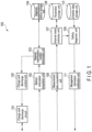
- FIG. 1 is a block diagram showing a battery control device according to an approach.
- a battery control device 100 according to the approach includes a charge and discharge circuit 101, a battery information acquisition unit 102, a diagnosis implementation condition determination unit 103, a diagnosis implementation history storage unit 104, a charge and discharge control unit 105, a measurement data acquisition unit 106, an internal state estimate unit 107, a parameter storage unit 108, a safety diagnosis unit 109, a criterion data storage unit 110, and a management information notification unit 111.
- the charge and discharge circuit 101 can charge and discharge a secondary battery electrically connected to the charge and discharge circuit 101. Specifically, the charge and discharge circuit 101 charges and discharges the secondary battery in accordance with a control of the charge and discharge control unit 105.
- the charge and discharge circuit 101 is electrically connected to an external power source (not shown), and controls a current flowing from the external power source to a secondary battery and vice versa, thereby charging and discharging the secondary battery.
- the charge and discharge circuit 101 is provided with a voltmeter capable of measuring a voltage between a positive electrode terminal and a negative electrode terminal of the secondary battery connected to the charge and discharge circuit 101, and an ammeter capable of measuring a current flowing in the connected secondary battery.
- the charge and discharge circuit 101 may be provided with a temperature sensor capable of measuring a temperature of the connected secondary battery.
- a temperature sensor capable of measuring a temperature of the connected secondary battery.
- the aforementioned ammeter, voltmeter, and temperature sensor are provided in a device on which the secondary battery connected to the charge and discharge circuit 101 is mounted.
- the secondary battery may be a nonaqueous electrolyte secondary battery such as a lithium-ion secondary battery, or a battery module having a plurality of nonaqueous electrolyte secondary batteries.
- the secondary battery may be electrically coupled to the charge and discharge circuit 101 after being removed from a device (namely, a changeable-type secondary battery), or electrically coupled to the charge and discharge circuit 101 while being mounted on the device.
- the device on which the secondary battery is mounted is typically a vehicle using electricity discharged from the secondary battery, but is not limited thereto; the device may be a drone or a smart phone, for example.
- the vehicle may be an electric vehicle, a plug-in hybrid electric vehicle, or an electric motorbike.
- the battery control device 100 may be included in a charging infrastructure installed in a parking lot as shown in FIG. 2 (for example, a charging station).
- FIG. 2 is a diagram showing an appearance of a parking lot system which includes the battery control device shown in FIG. 1 .
- the battery control device 100 charges the secondary battery, and diagnoses the safety and the deterioration state of the secondary battery under a certain condition.
- a single or a plurality of battery control devices 100 thus installed in a parking lot may be called a parking lot system.
- the charge and discharge circuits 101 of the plurality of battery control devices 100 may share an electric network, and may share the electricity to another charge and discharge circuit 101.
- a parking lot is not limited to a public parking lot, such as a coin-operated parking or a free parking lot, and may include a parking lot for specific users, such as a parking lot at a shopping center, an apartment house, a factory, a taxi office, or a bus switching yard.
- the device on which the secondary battery is mounted may be used for a rental service to non-specific users.
- the device on which the secondary battery is mounted may be an EV used for an EV sharing service.
- the secondary battery will be electrically connected to the charge and discharge circuit 101 after a user returns the device on which the secondary battery is mounted.
- a plurality of secondary batteries may be electrically connected to the charge and discharge circuit 101.
- the charge and discharge circuit 101 can charge one of the secondary batteries using the electricity discharged from the other secondary battery in accordance with the control of the charge and discharge control unit 105.
- the battery information acquisition unit 102 acquires information (hereinafter this may be referred to as "battery information") relating to the secondary battery targeted for the charging and discharging by the charge and discharge circuit 101.
- the battery information may include an identifier for identifying the secondary battery and/or a state of charge (SOC) of the secondary battery or information that can be a factor for estimating the SOC.
- the battery information acquisition unit 102 sends the acquired battery information to the diagnosis implementation condition determination unit 103. Examples of information that can be a factor for estimating a SOC of the secondary battery are a current measured by the aforementioned ammeter, and a history of charging and discharging of the secondary battery.
- An RFID tag for sending the secondary battery identifier may be attached to the secondary battery or the device on which the secondary battery is mounted.
- the battery information acquisition unit 102 may acquire the received secondary battery identifier via a communication interface (I/F), for example.
- the charge and discharge control unit 105 may put off the charging of the first secondary battery until a second secondary battery for which it is determined that a diagnosis implementation condition is satisfied appears.
- An upper limit can be determined for this stand-by time based on, for example, a time required for charging a first secondary battery, or a scheduled next use thereof. It is thereby possible to charge a first secondary battery through actively using electricity discharged from a second secondary battery, without disrupting a use cycle demanded of the first secondary battery.
- the measurement data acquisition unit 106 acquires, from the target battery or via the charge and discharge circuit 101, measurement data of a measurement result of electric characteristics of the target battery at a plurality points of time during the time of charging the target battery.
- the measurement data which is acquired by the measurement data acquisition unit 106 while the target battery is being charged from the charging start SOC, includes measurement data representing a relationship of a voltage and a current of the target battery relative to the charging time.
- the electric characteristics include a voltmeter-measurable voltage between the positive electrode terminal and the negative electrode terminal of the target battery, and an ammeter-measurable current flowing in the target battery.
- the electric characteristics include a temperature of the target battery measured by the temperature sensor.
- the acquisition of the measurement data may be achieved as needed between a time when the secondary battery is connected to the charge and discharge circuit and a time when the secondary battery is removed from the charge and discharge circuit after the secondary battery is discharged or charged up to a predetermined charging-start SOC and the charging is completed.
- the measurement data acquisition unit 106 sends the acquired measurement data to the internal state estimate unit 107.
- the internal state estimate unit 107 receives the measurement data from the measurement data acquisition unit 106, and estimates internal state parameters of the target battery based on the measurement data. Specifically, the internal state estimate unit 107 analyzes the measurement data representing the relationship of a voltage and a current of the target battery relative to a charging time. In one example, the internal state estimate unit 107 may perform an analysis on a charging curve of the target battery which is represented by the measurement data, in other words, a charging curve analysis.
- the internal state parameters may include some or all of the following: a positive electrode capacitance (or a positive electrode mass), a negative electrode capacitance (or a negative electrode mass), an initial charging amount of a positive electrode, an initial charging amount of a negative electrode, and an internal resistance.
- the internal state estimate unit 107 may estimate battery characteristic parameters of the target battery based on the estimated internal state parameters.
- the battery characteristic parameters may include, for example, some or all of the following: an open circuit voltage (OCV), an OCV curve, and a battery capacitance.
- OCV open circuit voltage
- the aforementioned internal resistance may be included in the battery characteristic parameters.
- the OCV curve represents a function expressing a relationship between a certain index other than the OCV of the target battery (for example the internal state parameter or the battery characteristic parameter) and a corresponding OCV.
- the battery capacitance corresponds to an overlapping portion of a range of the positive electrode capacitance (namely, a range from an initial charging amount to an upper limit charging amount of the positive electrode) and a range of the negative electrode capacitance (namely, a range from an initial charging amount to an upper limit charging amount of the negative electrode).
- the internal state estimate unit 107 may read necessary parameters from the parameter storage unit 108 and use them to estimate the internal state parameters and the battery characteristic parameters.
- the internal state estimate unit 107 may read the following parameters: a function that returns an open circuit potential (OCP) of the positive electrode corresponding to the SOC of the positive electrode, a function that returns an OCP of the negative electrode corresponding to the SOC of the negative electrode, an upper limit voltage and a lower limit voltage imposed on the OCV, an intermediate estimated value of a parameter for acquiring a final estimation result of a parameter of the target battery, and so on.
- the internal state estimate unit 107 may store, among the estimated parameters, parameters necessary for future parameter estimation in the parameter storage unit 108.
- the internal state estimate unit 107 sends, to the safety diagnosis unit 109, parameters necessary for the safety diagnosis of the target battery, among the estimated internal state parameters and battery characteristic parameters.
- the parameter storage unit 108 stores parameters necessary for the internal state estimate unit 107 to estimate the internal state parameters and the battery characteristic parameters. Specific examples of what is stored in the parameter storage unit 108 are as described above.
- the battery control device 100 may be realized by a computer.
- a computer includes a processor and a memory, and may further include a communication I/F, an auxiliary storage device, and I/O (input/output).
- the processor may function as, through executing the program developed on the memory, a battery information acquisition unit 102, a diagnosis implementation condition determination unit 103, a charge and discharge control unit 105, a measurement data acquisition unit 106, an internal state estimate unit 107, a safety diagnosis unit 109, and/or a management information notification unit 111, for example.
- the memory and/or auxiliary storage device may include a diagnosis implementation history storage unit 104, a parameter storage unit 108, and/or a criterion data storage unit 110.
Landscapes
- Engineering & Computer Science (AREA)
- Power Engineering (AREA)
- Transportation (AREA)
- Mechanical Engineering (AREA)
- Life Sciences & Earth Sciences (AREA)
- Sustainable Development (AREA)
- Sustainable Energy (AREA)
- Physics & Mathematics (AREA)
- General Physics & Mathematics (AREA)
- Manufacturing & Machinery (AREA)
- Chemical & Material Sciences (AREA)
- Chemical Kinetics & Catalysis (AREA)
- Electrochemistry (AREA)
- General Chemical & Material Sciences (AREA)
- Charge And Discharge Circuits For Batteries Or The Like (AREA)
- Secondary Cells (AREA)
- Electric Propulsion And Braking For Vehicles (AREA)
- Health & Medical Sciences (AREA)
- General Health & Medical Sciences (AREA)
- Medical Informatics (AREA)
- Tests Of Electric Status Of Batteries (AREA)
- Management, Administration, Business Operations System, And Electronic Commerce (AREA)
Description
- Disclosures described herein relate to a battery control device, a battery control method, and a battery control program.
- In recent years, the automobile field has promoted conversion from gasoline cars to electric vehicles (EV) and plug-in hybrid electric vehicles (PHEV) for their smaller impact on the environment. It is expected that this trend will lead to continuous growth of the EV market and expansion of charging infrastructure. On the other hand, the sharing economy has become more and more popular worldwide. For example, carsharing and ride sharing have been attracting attentions in the automobile field. Under these circumstances, EV carsharing may become popular in the future.
- EVs run on electricity discharged from a secondary battery, such as a lithium-ion battery (LIB), as an energy source. It has been reported that safety of LIBs deteriorates due to their cycle degradation.
-
US 2018/313906 A1 , relates to a battery system including a battery, a voltage detector that detects a voltage of the battery as a detected voltage value, a current detector that detects a current flowing through the battery as a detected current value and an electronic control unit. The electronic control unit is configured to estimate an aging deterioration of the battery based on an open circuit voltage value that is calculated from the detected voltage value and an integrated current value that is calculated from the detected current value, and estimate the aging deterioration of the battery based on the open circuit voltage value and the integrated current value that are calculated when a charge level of the battery is in the non-hysteresis region. -
-
FIG. 1 is a block diagram showing a battery control device according to an approach. -
FIG. 2 is a diagram showing an appearance of a parking lot system which includes the battery control device shown inFIG. 1 . -
FIG. 3 is a diagram showing a secondary battery reuse system in which an EV on-board secondary battery is reused as a stationary rechargeable battery. -
FIG. 4 is a flowchart showing an operation of the battery control device shown inFIG. 1 . - The present invention is defined by the independent claims.
- Approaches will be described hereinafter with reference to the accompanying drawings. Hereinafter, an element same as or similar to an already-explained element will be denoted with a same or similar reference symbol, and duplicate descriptions will be avoided.
-
FIG. 1 is a block diagram showing a battery control device according to an approach. As shown inFIG. 1 , abattery control device 100 according to the approach includes a charge anddischarge circuit 101, a batteryinformation acquisition unit 102, a diagnosis implementationcondition determination unit 103, a diagnosis implementationhistory storage unit 104, a charge anddischarge control unit 105, a measurementdata acquisition unit 106, an internalstate estimate unit 107, aparameter storage unit 108, asafety diagnosis unit 109, a criteriondata storage unit 110, and a managementinformation notification unit 111. - The charge and
discharge circuit 101 can charge and discharge a secondary battery electrically connected to the charge anddischarge circuit 101. Specifically, the charge anddischarge circuit 101 charges and discharges the secondary battery in accordance with a control of the charge anddischarge control unit 105. The charge anddischarge circuit 101 is electrically connected to an external power source (not shown), and controls a current flowing from the external power source to a secondary battery and vice versa, thereby charging and discharging the secondary battery. As one example, the charge anddischarge circuit 101 is provided with a voltmeter capable of measuring a voltage between a positive electrode terminal and a negative electrode terminal of the secondary battery connected to the charge anddischarge circuit 101, and an ammeter capable of measuring a current flowing in the connected secondary battery. The charge anddischarge circuit 101 may be provided with a temperature sensor capable of measuring a temperature of the connected secondary battery. As another example, the aforementioned ammeter, voltmeter, and temperature sensor are provided in a device on which the secondary battery connected to the charge anddischarge circuit 101 is mounted. - Herein, the secondary battery may be a nonaqueous electrolyte secondary battery such as a lithium-ion secondary battery, or a battery module having a plurality of nonaqueous electrolyte secondary batteries. Furthermore, the secondary battery may be electrically coupled to the charge and
discharge circuit 101 after being removed from a device (namely, a changeable-type secondary battery), or electrically coupled to the charge anddischarge circuit 101 while being mounted on the device. - The device on which the secondary battery is mounted is typically a vehicle using electricity discharged from the secondary battery, but is not limited thereto; the device may be a drone or a smart phone, for example.
- The vehicle may be an electric vehicle, a plug-in hybrid electric vehicle, or an electric motorbike.
- If the device on which the secondary battery is mounted is any of these vehicles, the
battery control device 100 may be included in a charging infrastructure installed in a parking lot as shown inFIG. 2 (for example, a charging station).FIG. 2 is a diagram showing an appearance of a parking lot system which includes the battery control device shown inFIG. 1 . After an EV 10 is parked in a parking lot and the secondary battery mounted on the EV 10 is electrically connected to the charge anddischarge circuit 101, thebattery control device 100 charges the secondary battery, and diagnoses the safety and the deterioration state of the secondary battery under a certain condition. A single or a plurality ofbattery control devices 100 thus installed in a parking lot may be called a parking lot system. The charge anddischarge circuits 101 of the plurality ofbattery control devices 100 may share an electric network, and may share the electricity to another charge anddischarge circuit 101. - A parking lot is not limited to a public parking lot, such as a coin-operated parking or a free parking lot, and may include a parking lot for specific users, such as a parking lot at a shopping center, an apartment house, a factory, a taxi office, or a bus switching yard.
- The device on which the secondary battery is mounted may be used for a rental service to non-specific users. As an example, the device on which the secondary battery is mounted may be an EV used for an EV sharing service. In this case, the secondary battery will be electrically connected to the charge and
discharge circuit 101 after a user returns the device on which the secondary battery is mounted. - A plurality of secondary batteries may be electrically connected to the charge and
discharge circuit 101. In this case, the charge anddischarge circuit 101 can charge one of the secondary batteries using the electricity discharged from the other secondary battery in accordance with the control of the charge anddischarge control unit 105. - The battery
information acquisition unit 102 acquires information (hereinafter this may be referred to as "battery information") relating to the secondary battery targeted for the charging and discharging by the charge anddischarge circuit 101. The battery information may include an identifier for identifying the secondary battery and/or a state of charge (SOC) of the secondary battery or information that can be a factor for estimating the SOC. The batteryinformation acquisition unit 102 sends the acquired battery information to the diagnosis implementationcondition determination unit 103. Examples of information that can be a factor for estimating a SOC of the secondary battery are a current measured by the aforementioned ammeter, and a history of charging and discharging of the secondary battery. - A bar code of the secondary battery identifier may be adhered or printed on the secondary battery or the device on which the secondary battery is mounted (e.g., a vehicle). In this case, the battery
information acquisition unit 102 can acquire the secondary battery identifier by decoding the bar code shown in image data acquired by a camera, for example. - Alternatively, instead of the bar code, the identifier itself may be adhered or printed on the secondary battery or the device on which the secondary battery is mounted. In this case, the battery
information acquisition unit 102 can acquire the secondary battery identifier by performing optical character recognition (OCR) processing on the identifier shown on image data acquired by a camera, for example. - An RFID tag for sending the secondary battery identifier may be attached to the secondary battery or the device on which the secondary battery is mounted. In this case, the battery
information acquisition unit 102 may acquire the received secondary battery identifier via a communication interface (I/F), for example. - The SOC of the secondary battery may be calculated by a controller connected to the secondary battery or the device on which the secondary battery is mounted (e.g., a vehicle) for example, and sent to an external device. In this case, the battery
information acquisition unit 102 can acquire the received SOC of the secondary battery via the communication I/F, for example. - Alternatively, instead of the SOC of the secondary battery, information relating to an operation history of the device on which the secondary battery is mounted, such as a driving time and a distance traveled, may be stored in the device and sent to an external device. In this case, the battery
information acquisition unit 102 may estimate the SOC of the secondary battery based on the information relating to the operation history of the device received via the communication I/F, for example. To estimate the SOC of the secondary battery, the batteryinformation acquisition unit 102 may use a function representing a relationship between a driving time or a distance traveled of the device, on which the secondary battery is mounted, and the SOC of the secondary battery. Such a function may be predefined based on a result of experiment and/or simulation, for example. - The diagnosis implementation
condition determination unit 103 receives, from the batteryinformation acquisition unit 102, the battery information of the secondary battery electrically connected to the charge and discharge circuit 101 (hereinafter, this may be referred to as "target battery"), and determines whether or not a diagnosis implementation condition relating to the target battery is satisfied based on the battery information. The diagnosis implementationcondition determination unit 103 sends, to the charge anddischarge control unit 105, a determination result indicating whether or not the diagnosis implementation condition relating to the target battery is satisfied. - As will be described later, the estimation of an internal state parameter, which is performed prior to a safety diagnosis of the target battery, uses measurement data at the time when the target battery in a predetermined charging-start SOC is charged. For this reason, the lower a value of the charging-start SOC is, the more substantial the measurement data becomes; thus, parameters (which will be described later) can be precisely estimated and the safety diagnosis can be performed with high reliability. On the other hand, when the SOC of the target battery exceeds the charging-start SOC, it is necessary to discharge the target battery due to a difference in the levels of these SOCs, and this may cause a waste of electricity. Assuming that the secondary battery is charged on a once-a-day basis or so, it may not always be necessary to perform the safety diagnosis every time the battery is charged, as the secondary battery deteriorates more slowly in most cases than this once-a-day charging cycle.
- Specifically, the diagnosis implementation
condition determination unit 103 may determine whether or not a diagnosis implementation condition is satisfied on the basis of the implementation history of the safety diagnosis of the target battery and the SOC of the target battery. The diagnosis implementation condition may include a condition that a time elapsed since the safety diagnosis was last performed on the target battery must exceed a threshold value, for example three months. The diagnosis implementation condition also includes a condition that the SOC of the target battery be equal to or lower than a threshold value, for example 20%. Furthermore, the diagnosis implementation condition may include a condition that a time elapsed since the safety diagnosis was last performed on the target battery must exceed a threshold value, for example one month/two months, and the SOC of the target battery be equal to or lower than a threshold value, for example 30%/40%. As an example, the diagnosis implementation condition relating to both of the elapsed time and the SOC may be determined in such a manner that the greater a threshold relating to the elapsed time becomes, the greater a threshold relating to the SOC becomes. - The diagnosis implementation
condition determination unit 103 may read an implementation history of the safety diagnosis of the target battery from the diagnosis implementationhistory storage unit 104. Herein, the diagnosis implementationhistory storage unit 104 may store a database in which the secondary battery identifier is associated with the implementation history of the safety diagnosis of the secondary battery. In this case, the diagnosis implementationcondition determination unit 103 can search the diagnosis implementationhistory storage unit 104 for a last day or time the safety diagnosis was performed on the target battery, using the target battery identifier as a key. - Herein, the implementation history includes at least a day or time of the last safety diagnosis performed on the secondary battery. Other than that, the implementation history may include the following: a result of the past safety diagnosis performed on the secondary battery, a result of estimating internal state parameters/battery characteristic parameters used as bases for the safety diagnosis, measurement data used as a basis for the estimation of the internal state parameters/battery characteristic parameters, information provided by the management information notification unit 111 (which will be described later), and the like.
- As mentioned, the diagnosis implementation
history storage unit 104 may store a database in which the secondary battery identifier is associated with the implementation history of the safety diagnosis of the secondary battery. The diagnosis implementationhistory storage unit 104 may be provided in a server connectible to thebattery control device 100 via a network. In this case, thebattery control device 100 may request, via the network, that this diagnosis implementationhistory storage unit 104 search for the implementation history of the safety diagnosis of the secondary battery associated with a predetermined identifier. It is thus possible to centrally manage the history of the safety diagnoses performed by differentbattery control devices 100. The implementation history of the safety diagnosis stored in the diagnosis implementationhistory storage unit 104 may be updated by various function units included in thebattery control device 100. - The charge and
discharge control unit 105 receives, from the diagnosis implementationcondition determination unit 103, a determination result as to whether or not a diagnosis implementation condition relating to the target battery is satisfied. If it is determined that a diagnosis implementation condition is satisfied, the charge anddischarge control unit 105 controls the charge anddischarge circuit 101 to charge the target battery only after discharging the target battery up to a predetermined charging-start SOC. If the SOC of the target battery is lower than the predetermined charging-start SOC, the discharging is not performed, and the target battery is charged up to the predetermined charging-start SOC. In contrast, if it is determined that a diagnosis implementation condition is not satisfied, the charge anddischarge control unit 105 may control the charge anddischarge circuit 101 to simply charge the target battery. - Herein, the charging-start SOC is determined to be 20%, for example. The charging-start SOC may be the same for any target battery or may differ between target batteries. In the latter case, the charging-start SOC is variable depending on a type of the target battery (for example, a composition of an active material), the implementation history of the safety diagnosis of the target battery, and so on. The charging from the predetermined charging-start SOC may be defined to be equal to or lower than a current value 1C, for example. The conditions for the charging-start SOC and the charging current are determined within a range acceptable for the characteristic of the secondary battery and the method performed by the internal state estimation unit.
- If it is determined that the diagnosis implementation condition regarding the target battery is satisfied, and another secondary battery that needs to be charged is electrically connected to the charge and
discharge circuit 101, the charge anddischarge control unit 105 may control the charge anddischarge circuit 101 to charge this another secondary battery with electricity discharged from the target battery when the target battery is discharged up to the predetermined charging-start SOC. It is thereby possible to reduce a waste of electricity caused by discharging of the target battery. For example, if the diagnosis implementationcondition determination unit 103 of thebattery control device 100 included in a parking lot system determines that a diagnosis condition relating to the target battery mounted on an EV is satisfied, and a secondary battery mounted on another EV that needs to be charged is electrically connected the charge anddischarge circuit 101 of thebattery control device 100, the charge anddischarge control unit 105 of thebattery control device 100 may control the charge anddischarge circuit 101 to charge the secondary battery mounted on this another EV with electricity discharged from the target battery, when the target battery is discharged up to the predetermined charging-start SOC. The above-described control on the charge anddischarge circuit 101 performed by thebattery control device 100 in the parking lot system is applicable even to a case where a device on which the secondary battery is mounted is other than an automobile. In other words, as long as the system is a charge and discharge system in which a plurality of devices on which a secondary battery is respectively mounted are provided, the above-described control of the charge anddischarge circuit 101 performed by thebattery control device 100 is applicable. - Furthermore, in order to improve an implementation rate of such efficient charging, if, for example, a diagnosis implementation condition relating to a first secondary battery is not satisfied, the charge and
discharge control unit 105 may put off the charging of the first secondary battery until a second secondary battery for which it is determined that a diagnosis implementation condition is satisfied appears. An upper limit can be determined for this stand-by time based on, for example, a time required for charging a first secondary battery, or a scheduled next use thereof. It is thereby possible to charge a first secondary battery through actively using electricity discharged from a second secondary battery, without disrupting a use cycle demanded of the first secondary battery. - The measurement
data acquisition unit 106 acquires, from the target battery or via the charge anddischarge circuit 101, measurement data of a measurement result of electric characteristics of the target battery at a plurality points of time during the time of charging the target battery. The measurement data, which is acquired by the measurementdata acquisition unit 106 while the target battery is being charged from the charging start SOC, includes measurement data representing a relationship of a voltage and a current of the target battery relative to the charging time. Herein, the electric characteristics include a voltmeter-measurable voltage between the positive electrode terminal and the negative electrode terminal of the target battery, and an ammeter-measurable current flowing in the target battery. The electric characteristics include a temperature of the target battery measured by the temperature sensor. The acquisition of the measurement data may be achieved as needed between a time when the secondary battery is connected to the charge and discharge circuit and a time when the secondary battery is removed from the charge and discharge circuit after the secondary battery is discharged or charged up to a predetermined charging-start SOC and the charging is completed. The measurementdata acquisition unit 106 sends the acquired measurement data to the internalstate estimate unit 107. - The internal
state estimate unit 107 receives the measurement data from the measurementdata acquisition unit 106, and estimates internal state parameters of the target battery based on the measurement data. Specifically, the internalstate estimate unit 107 analyzes the measurement data representing the relationship of a voltage and a current of the target battery relative to a charging time. In one example, the internalstate estimate unit 107 may perform an analysis on a charging curve of the target battery which is represented by the measurement data, in other words, a charging curve analysis. The internal state parameters may include some or all of the following: a positive electrode capacitance (or a positive electrode mass), a negative electrode capacitance (or a negative electrode mass), an initial charging amount of a positive electrode, an initial charging amount of a negative electrode, and an internal resistance. - Furthermore, the internal
state estimate unit 107 may estimate battery characteristic parameters of the target battery based on the estimated internal state parameters. The battery characteristic parameters may include, for example, some or all of the following: an open circuit voltage (OCV), an OCV curve, and a battery capacitance. Furthermore, the aforementioned internal resistance may be included in the battery characteristic parameters. Herein, the OCV curve represents a function expressing a relationship between a certain index other than the OCV of the target battery (for example the internal state parameter or the battery characteristic parameter) and a corresponding OCV. The battery capacitance corresponds to an overlapping portion of a range of the positive electrode capacitance (namely, a range from an initial charging amount to an upper limit charging amount of the positive electrode) and a range of the negative electrode capacitance (namely, a range from an initial charging amount to an upper limit charging amount of the negative electrode). - The internal
state estimate unit 107 may read necessary parameters from theparameter storage unit 108 and use them to estimate the internal state parameters and the battery characteristic parameters. For example, the internalstate estimate unit 107 may read the following parameters: a function that returns an open circuit potential (OCP) of the positive electrode corresponding to the SOC of the positive electrode, a function that returns an OCP of the negative electrode corresponding to the SOC of the negative electrode, an upper limit voltage and a lower limit voltage imposed on the OCV, an intermediate estimated value of a parameter for acquiring a final estimation result of a parameter of the target battery, and so on. The internalstate estimate unit 107 may store, among the estimated parameters, parameters necessary for future parameter estimation in theparameter storage unit 108. - The charging curve analysis is publicly known through, for example, Jpn. Pat. Appln. KOKAI Publication No. 2017-166874, and the internal
state estimate unit 107 can estimate the internal state parameters of the target battery, and, if necessary, the battery characteristic parameters of the target battery, through using the publicly-known method. - The internal
state estimate unit 107 sends, to thesafety diagnosis unit 109, parameters necessary for the safety diagnosis of the target battery, among the estimated internal state parameters and battery characteristic parameters. - The
parameter storage unit 108 stores parameters necessary for the internalstate estimate unit 107 to estimate the internal state parameters and the battery characteristic parameters. Specific examples of what is stored in theparameter storage unit 108 are as described above. - The
safety diagnosis unit 109 receives an estimation result of parameters of the target battery from the internalstate estimate unit 107, and diagnoses the target battery for its safety and remaining life span, etc. based on the received estimation result, and diagnoses a deterioration state of the target battery. Specifically, thesafety diagnosis unit 109 reads, from the criteriondata storage unit 110, criterion data indicating a criterion corresponding to each of at least one diagnosis item relating to the safety of the target battery. Then, thesafety diagnosis unit 109 diagnoses, for each diagnosis item, the estimation result of parameters of the target battery to determine whether or not the estimation result satisfies the criterion. Thesafety diagnosis unit 109 sends a diagnosis result on the safety of the target battery to the managementinformation notification unit 111. - The
safety diagnosis unit 109 may predict the life span of the target battery based on the diagnosis result on the safety of the target battery. Thesafety diagnosis unit 109 may predict a specific value as the life span of the target battery, for example three years, or may grade the life span into five ranks, for example. Thesafety diagnosis unit 109 may send the predicted life span of the target battery to the managementinformation notification unit 111, along with the diagnosis result of the target battery. Furthermore, the predicted life span of the target battery may be sent to an external device to lay out a reuse program (which will be described later), for example. - Herein, the criterion data may indicate a normal numerical range for a corresponding parameter. In this case, with respect to a certain diagnosis item, if the parameter estimation result deviates from the numerical range of the criterion data, the
safety diagnosis unit 109 may diagnose the target battery as not satisfying the criterion for the diagnosis item. On the other hand, with respect to a certain diagnosis item, if the parameter estimation result falls within the numerical range of the criterion data, thesafety diagnosis unit 109 may diagnose the target battery as satisfying the criterion for the diagnosis item. - The diagnosis items may include some or all of the following: a positive electrode capacitance, a negative electrode capacitance, and a difference between an initial charging amount of the positive electrode and an initial charging amount of the negative electrode. The
safety diagnosis unit 109 may diagnose the target battery as failing to satisfy the criterion for the positive electrode capacitance, if the estimation result for the positive electrode capacitance of the target battery is smaller than a threshold value indicated by the criterion data regarding the positive electrode capacitance. Thesafety diagnosis unit 109 may diagnose the target battery as failing to satisfy the criterion for the negative electrode capacitance, if the estimation result for the negative electrode capacitance of the target battery is smaller than a threshold value indicated by the criterion data regarding the negative electrode capacitance. Furthermore, if a difference between an estimation result of the initial charging amount of the positive electrode and an estimation result of the initial charging amount of the negative electrode exceeds a threshold indicated by the criterion data regarding a difference between the initial charging amount of the positive electrode and the initial charging amount of the negative electrode in the target battery, thesafety diagnosis unit 109 may diagnose the target battery as failing to satisfy a criterion regarding said difference. - The criterion
data storage unit 110 stores criterion data for each diagnosis item. The criterion data may be variable depending on a type of the target battery (for example, a composition of an active material), a type of a device on which the target battery is mounted (for example, whether it is an EV or a stationary rechargeable battery), and an implementation history of the safety diagnosis of the target battery. - The management
information notification unit 111 receives, from thesafety diagnosis unit 109, a diagnosis result on the safety of the target battery, namely a diagnosis result on the deterioration state of the target battery, and notifies, for example, an owner or a manager of the target battery and the device on which the target battery is mounted of management information relating to the target battery or the device based on the diagnosis result. For example, the managementinformation notification unit 111 may output, from an output device connected to thebattery control device 100, such as a display or a speaker, content for reporting the management information, such as text, static images, moving images, or sound. Alternatively, the managementinformation notification unit 111 may send a message, for example, an email or an SNS message, to notify an address associated with the target battery or the device on which the target battery is mounted of the management information, via the communication I/F. - The management
information notification unit 111 may report that a stop of use of the target battery is recommended, if the target battery is diagnosed as failing to satisfy at least one diagnosis item. It is thus possible to dissuade the owner or the manager from continuously using the target battery, and to prevent accidents due to deterioration of the target battery. - The management
information notification unit 111 may report that a reuse of the target battery is recommended instead of or in addition to the reporting that a stop of use of the target battery is recommended, if the target battery is diagnosed as failing to satisfy at least one diagnosis item. - Whereas a criterion for the safety of a secondary battery mounted on a vehicle such as an EV is strictly defined so as to prevent any critical accidents due to malfunctioning of the battery, the same level of strictness may not be required for a criterion for a secondary battery which is mounted on a battery product other than a vehicle, such as a stationary rechargeable battery. Accordingly, as shown in
FIG. 3 , for example, a business model wherein a secondary battery having a predicted life span longer than a certain length among secondary batteries mounted on an EV, in other words, a secondary battery in which deterioration is not so advanced, is selected and collected, and remanufactured as a stationary rechargeable battery, may be possible.FIG. 3 is a diagram showing a secondary battery reuse system in which an EV on-board secondary battery is reused as a stationary rechargeable battery. Such a stationary rechargeable battery can be used as a storage for green energy, such as wind energy and solar energy, in a large-scale energy storage system. - When reporting that a reuse of the target battery is recommended, the management
information notification unit 111 may further report a reuse program available for the target battery. In this case, a reuse program for the target battery may be externally provided, for example to an owner of the target battery, by the managementinformation notification unit 111. This reuse program may include a type of reuse (whether a full purchase of the target battery, a receipt of a difference in price as a result of downgrading the target battery, or a payment of a difference in price as a result of upgrading the target battery), a price regarding the reuse (a purchase price, a difference in price in the case of downgrading/upgrading), and an expiry date of the reuse, for example. The managementinformation notification unit 111 may inquire with an external device, for example an external device (server) connectible via a network, about a reuse program available for the target battery. Furthermore, this external device may send a reuse program available to the target battery to thebattery control device 100 in accordance with the inquiry (in other words, the external device may answer to the inquiry). If the owner of the target battery agrees to the reuse program, the target battery is collected, and remanufactured as a stationary rechargeable battery of a large-scale energy storage system, for example. The managementinformation notification unit 111 may ensure that the inquiry includes a diagnosis result on safety and a deterioration rate of the target battery and/or a predicted life span. Herein, the managementinformation notification unit 111 may acquire information indicating that the owner of the target battery has agreed to the reuse program. Upon acquisition of the information indicating that the owner has agreed to the reuse program, the managementinformation notification unit 111 may report that the target battery has been remanufactured as a secondary battery to be mounted on a battery product, such as a stationary rechargeable battery, etc. - The management
information notification unit 111 does not need to report that a reuse of the target battery is recommended, if the deterioration of the target battery progresses to the extent that the reuse is difficult. Specifically, the managementinformation notification unit 111 may report that a stop of use of the target battery is recommended without reporting that a reuse of the target battery is recommended, if the predicted life span of the target battery received from thesafety diagnosis unit 109 is shorter than a threshold value. - Furthermore, the management
information notification unit 111 may report that the charging of the target battery is finished, or a use or rent of the target battery or a device on which the target battery is mounted is ready, if the target battery is diagnosed as satisfying a criterion for each diagnosis item. The managementinformation notification unit 111 may also report similar management information when the charging of the target battery is finished, if it is determined that a diagnosis implementation condition relating to the target battery is not satisfied. - An example of the operation of the
battery control device 100 shown inFIG. 1 will be explained with reference toFIG. 4. FIG. 4 is a flowchart showing an operation of the battery control device shown inFIG. 1 .FIG. 4 shows an example of the operation of thebattery control device 100 between a time when the target battery mounted on theEV 10 is electrically connected to the charge anddischarge circuit 101 and a time when the charging is finished, for example. - When the operation shown in
FIG. 4 starts, the batteryinformation acquisition unit 102 acquires the battery information of the target battery (step S201). Next, the diagnosis implementationcondition determination unit 103 determines whether or not the diagnosis implementation condition relating to the target battery is satisfied based on the battery information acquired in step S201 (step S202). In step S202, the processing proceeds to step S205 if it is determined that the diagnosis implementation condition is satisfied in step S202; if the condition is not satisfied, the processing proceeds to step S203. - In step S203, the charge and
discharge control unit 105 controls the charge anddischarge circuit 101 to charge the target battery. After step S203, the processing proceeds to step S204. - In step S204, the management
information notification unit 111 reports that the target battery or the device on which the target battery is mounted is ready, and then the operation inFIG. 4 is finished. The managementinformation notification unit 111 may report that the charging of the target battery has been finished, or that the target battery or the device on which the target battery is mounted is ready for use, instead of or in addition to the management information. - In step S205, the charge and
discharge control unit 105 controls the charge anddischarge circuit 101 to discharge or charge the target battery up to the charging-start SOC. - In step S205, if another secondary battery is electrically connected to the charge and
discharge circuit 101, the charge anddischarge control unit 105 controls the charge anddischarge circuit 101 to charge this another secondary battery with electricity discharged from the target battery (step S206 and step S207). - After step S205 through step S207, the charge and
discharge control unit 105 controls the charge anddischarge circuit 101 to charge the target battery (step S208). Then, the measurementdata acquisition unit 106 acquires measurement data at the time of charging the target battery in step S208 (step S209). - The internal
state estimate unit 107 estimates the internal state parameters of the target battery, and if necessary, the battery characteristic parameters of the target battery, based on the measurement data acquired in step S209 (step S210). - The
safety diagnosis unit 109 diagnoses whether or not the target battery satisfies a criterion for each of at least one diagnosis item, based on at least some of the parameters estimated in step S210 (step S211). - If a diagnosis result indicating that the target battery satisfies a criterion for each diagnosis item is acquired in step S211, the processing proceeds to step S204; if not, the processing proceeds to step S213.
- In step S213, the management
information notification unit 111 reports that a stop of use and/or a reuse of the target battery is recommended, and the operation shown inFIG. 4 is subsequently finished. - As described above, the battery control device according to the present approach determines whether or not a diagnosis implementation condition relating to a secondary battery electrically connected to the charge and discharge circuit is satisfied, and if the condition is satisfied, the secondary battery is discharged and then charged. Furthermore, this battery control device estimates parameters relating to the secondary battery based on the measurement data of the secondary battery at the time of charging, and diagnoses the secondary battery for its safety based on this estimation result. For this reason, according to this battery control device, the safety diagnosis is performed at an appropriate timing, for example when the SOC is equal to or smaller than a threshold value, and/or when a time elapsed since the last safety diagnosis exceeds a threshold value; therefore, the discharging of the secondary battery does not occur too often. In other words, according to this battery control device, it is possible to acquire sufficient measurement data with a sufficient length of charging range, while a waste of electricity caused by the discharging of a secondary battery is reduced, and to improve accuracy in parameter estimation and reliability in safety diagnosis.
- Furthermore, as an option, this battery control device may charge a secondary battery electrically connected to the charge and discharge circuit through utilizing electricity discharged from another secondary battery. It is thereby possible to further reduce a waste of electricity caused by discharging of the secondary battery.
- In the foregoing approach, several function units are explained, but the explanation is merely an example of implementation of each function unit. For example, a plurality of function units that are described as being implemented in one device may be implemented in several different devices, and a function unit that is described as being implemented in several devices may be implemented in one device.
- The various function units explained in the forgoing approach may be realized through a use of a circuit. A circuit may be a dedicated circuit that realizes specific functions, or may be a general-purpose circuit such as a processor.
- At least a part of the processing in the foregoing approach may be achieved by using a processor, such as a CPU and/or a GPU, a micro computer, an FPGA, or a DSP, mounted on a general-purpose computer, as basic hardware. A program that realizes the above processing may be provided in a form of a non-transitory computer-readable recording medium storing the program thereon. The program may be stored in a non-transitory recording medium in an installable or executable file format. The recording medium is for example a magnetic disk, an optical disk (CD-ROM, CD-R, DVD, etc.), a magneto-optical disk (MO, etc.), or a semiconductor memory. The recording medium may be of any type, as long as it is capable of storing a program and computer-readable. The program that realizes the foregoing processing may be stored on a computer (server) connected to a network, such as Internet, and may be downloaded onto a computer (client) via the network.
- Specifically, the
battery control device 100 according to the foregoing approach may be realized by a computer. Such a computer includes a processor and a memory, and may further include a communication I/F, an auxiliary storage device, and I/O (input/output). The processor may function as, through executing the program developed on the memory, a batteryinformation acquisition unit 102, a diagnosis implementationcondition determination unit 103, a charge anddischarge control unit 105, a measurementdata acquisition unit 106, an internalstate estimate unit 107, asafety diagnosis unit 109, and/or a managementinformation notification unit 111, for example. The memory and/or auxiliary storage device may include a diagnosis implementationhistory storage unit 104, aparameter storage unit 108, and/or a criteriondata storage unit 110. - While certain approaches have been described, these approaches have been presented by way of example only, and are not intended to limit the scope of the claims. Indeed, the apparatuses described herein may be embodied in a variety of other forms; furthermore, various omissions, substitutions and changes in the form of the apparatuses described herein may be made without departing from the scope of the appended claims.
Claims (13)
- A battery control device (100) comprising:a charge and discharge circuit (101) capable of charging and discharging an electrically connected secondary battery; anda processor configured to control the charge and discharge circuit (101), whereinthe processor is configured to:acquire information regarding a first secondary battery electrically connected to the charge and discharge circuit (101), the information regarding the first secondary battery including a state of charge, SOC, of the first secondary battery;determine whether or not a diagnosis implementation condition regarding the first secondary battery is satisfied based on the information regarding the first secondary battery, the diagnosis implementation condition including a condition that the SOC of the first secondary battery is equal to or smaller than a first threshold value;control the charge and discharge circuit (101) to charge the first secondary battery up to a charging start SOC if it is determined that the diagnosis implementation condition is satisfied and the SOC of the first secondary battery is lower than the charging start SOC, the charging start SOC being lower than the first threshold value;control the charge and discharge circuit (101) to discharge the first secondary battery up to the charging start SOC if it is determined that the diagnosis implementation condition is satisfied and the SOC of the first secondary battery is higher than the charging start SOC;control the charge and discharge circuit (101) to charge the first secondary battery from the charging start SOC consecutively after discharging or charging the first secondary battery up to the charging start SOC;acquire measurement data of a voltage and a current of the first secondary battery while the first secondary battery is being charged from the charging start SOC;estimate an internal state parameter of the first secondary battery based on the measurement data; anddiagnose a deterioration state of the first secondary battery based on an estimated value of the internal state parameter of the first secondary battery; andcontrol the charge and discharge circuit (101) to charge a second secondary battery differing from the first secondary battery with electricity discharged from the first secondary battery up to the charging start SOC, if it is determined that the diagnosis implementation condition is satisfied and the second secondary battery is electrically connected to the charge and discharge circuit (101).
- The battery control device (100) according to claim 1, wherein
the processor is configured to determine whether or not the diagnosis implementation condition is satisfied based on an implementation history of diagnosis of a deterioration state of the first secondary battery and whether or not the SOC of the first secondary battery is equal to or smaller than the first threshold value. - The battery control device (100) according to claim 1, wherein
the diagnosis implementation condition includes a condition that a time elapsed since a last diagnosis of a deterioration state of the first secondary battery exceeds a second threshold value, and the condition that the SOC of the first secondary battery is equal to or smaller than the first threshold value. - The battery control device (100) according to claim 1, whereinthe processor is configured to report that a stop of use or a reuse of the first secondary battery is recommended if it is determined that the first secondary battery does not satisfy a criterion for at least one diagnosis item, andthe reporting that a reuse is recommended includes notifying a reuse program of the first secondary battery.
- The battery control device (100) according to claim 4, wherein
the reuse program includes at least one of a type of reuse, a price regarding reuse, or an expiry date of reuse. - The battery control device (100) according to claim 1, whereinthe processor is configured to report that a stop of use or a reuse of the first secondary battery is recommended if it is determined that the first secondary battery does not satisfy a criterion for at least one diagnosis item,the first secondary battery is mounted on a device (10) rented to a user,the first secondary battery is electrically connected to the charge and discharge circuit (101) after the device (10) is returned by the user, andthe processor is configured to report that the device (10) is ready to rent when it is determined that the first secondary battery satisfies a criterion for each of at least one diagnosis item.
- The battery control device (100) according to claim 1, wherein
the processor is configured to analyze a charging curve of the first secondary battery represented by the measurement data, and thereby configured to estimate the internal state parameter. - A charge and discharge system comprising:the battery control device (100) according to any one of claims 1 to 7; anda first device (10) on which the first secondary battery is mounted, and which is connectable to the charge and discharge circuit (101), whereinif it is determined that the diagnosis implementation condition is satisfied and the second secondary battery mounted on a second device differing from the first device (10) is electrically connected to the charge and discharge circuit (101), the processor is configured to control the charge and discharge circuit (101) to charge the second secondary battery with electricity discharged from the first secondary battery up to the charging start SOC.
- A parking lot system comprising:the battery control device (100) according to any one of claims 1 to 7 installed in a parking lot; anda first vehicle (10) on which the first secondary battery is mounted, whereinthe first secondary battery is electrically connected to the charge and discharge circuit (101) at the moment when the first vehicle (10) is parked in the parking lot, andif it is determined that the diagnosis implementation condition is satisfied and the second secondary battery mounted on a second vehicle differing from the first vehicle (10) is electrically connected to the charge and discharge circuit (101), the processor is configured to control the charge and discharge circuit (101) to charge the second secondary battery with electricity discharged from the first secondary battery up to the charging start SOC.
- A secondary battery reuse system comprising:the battery control device (100) according to any one of claims 1 to 7, whereinthe processor is configured to externally provide a reuse program of the first secondary battery if the first secondary battery is diagnosed as failing to satisfy a criterion of at least one diagnosis item, andthe processor is configured to report that the first secondary battery will be remanufactured as a secondary battery to be mounted on a battery product, upon acquisition of information indicating that an owner of the first secondary battery agrees to the reuse program.
- A secondary battery reuse system comprising:the battery control device (100) according to any one of claims 1 to 7; anda server, wherein
the processor is configured to externally provide a reuse program of the first secondary battery if the first secondary battery is diagnosed as failing to satisfy a criterion of at least one diagnosis item, andthe processor is configured to make an inquiry to the server regarding a reuse program available for the first secondary battery, and configured to further provide a reuse program sent by the server in response to the inquiry. - A battery control method comprising:acquiring information relating to a first secondary battery electrically connected to a charge and discharge circuit (101) capable of charging and discharging an electrically connected secondary battery, the information regarding the first secondary battery including a state of charge, SOC, of the first secondary battery;determining whether or not a diagnosis implementation condition regarding the first secondary battery is satisfied based on the information regarding the first secondary battery, the diagnosis implementation condition including a condition that the SOC of the first secondary battery is equal to or smaller than a first threshold value;controlling the charge and discharge circuit (101) to charge the first secondary battery up to a charging start SOC if it is determined that the diagnosis implementation condition is satisfied and the SOC of the first secondary battery is lower than the charging start SOC, the charging start SOC being lower than the first threshold value;controlling the charge and discharge circuit (101) to discharge the first secondary battery up to the charging start SOC if it is determined that the diagnosis implementation condition is satisfied and the SOC of the first secondary battery is higher than the charging start SOC;controlling the charge and discharge circuit (101) to charge the first secondary battery from the charging start SOC consecutively after discharging or charging the first secondary battery up to the charging start SOC;acquiring measurement data of a voltage and a current of the first secondary battery while the first secondary battery is charged from the charging-start SOC;estimating an internal state parameter of the first secondary battery based on the measurement data; anddiagnosing a deterioration state of the first secondary battery based on an estimated value of the internal state parameter of the first secondary battery; andcontrolling the charge and discharge circuit (101) to charge a second secondary battery differing from the first secondary battery with electricity discharged from the first secondary battery up to the charging start SOC, if it is determined that the diagnosis implementation condition is satisfied and the second secondary battery is electrically connected to the charge and discharge circuit (101).
- A battery control program, when executed by a computer, causes the computer to:acquire information relating to a first secondary battery electrically connected to a charge and discharge circuit (101) capable of charging and discharging an electrically connected secondary battery, the information regarding the first secondary battery including a state of charge, SOC, of the first secondary battery;determine whether or not a diagnosis implementation condition regarding the first secondary battery is satisfied based on the information regarding the first secondary battery, the diagnosis implementation condition including a condition that the SOC of the first secondary battery is equal to or smaller than a first threshold value;control the charge and discharge circuit (101) to charge the first secondary battery up to a charging start SOC if it is determined that the diagnosis implementation condition is satisfied and the SOC of the first secondary battery is lower than the charging start SOC, the charging start SOC being lower than the first threshold value;control the charge and discharge circuit (101) to discharge the first secondary battery up to the charging start SOC if it is determined that the diagnosis implementation condition is satisfied and the SOC of the first secondary battery is higher than the charging start SOC;control the charge and discharge circuit (101) to charge the first secondary battery from the charging start SOC consecutively after discharging or charging the first secondary battery up to the charging start SOC;acquire measurement data of a voltage and a current of the first secondary battery while the first secondary battery is being charged from the charging-start SOC;estimate an internal state parameter of the first secondary battery based on the measurement data; anddiagnose a deterioration state of the first secondary battery based on an estimated value of the internal state parameter of the first secondary battery; andcontrol the charge and discharge circuit (101) to charge a second secondary battery differing from the first secondary battery with electricity discharged from the first secondary battery up to the charging start SOC, if it is determined that the diagnosis implementation condition is satisfied and the second secondary battery is electrically connected to the charge and discharge circuit (101).
Applications Claiming Priority (1)
| Application Number | Priority Date | Filing Date | Title |
|---|---|---|---|
| JP2019168411A JP2021048663A (en) | 2019-09-17 | 2019-09-17 | Battery control device, charge / discharge system, parking system, secondary battery reuse system, battery control method, and battery control program |
Publications (2)
| Publication Number | Publication Date |
|---|---|
| EP3796014A1 EP3796014A1 (en) | 2021-03-24 |
| EP3796014B1 true EP3796014B1 (en) | 2025-07-02 |
Family
ID=69742753
Family Applications (1)
| Application Number | Title | Priority Date | Filing Date |
|---|---|---|---|
| EP20159777.0A Active EP3796014B1 (en) | 2019-09-17 | 2020-02-27 | Battery control device, charge and discharge system, parking lot system, secondary battery reuse system, battery control method, and battery control program |
Country Status (4)
| Country | Link |
|---|---|
| US (1) | US11201486B2 (en) |
| EP (1) | EP3796014B1 (en) |
| JP (2) | JP2021048663A (en) |
| CN (1) | CN112519631B (en) |
Families Citing this family (15)
| Publication number | Priority date | Publication date | Assignee | Title |
|---|---|---|---|---|
| JP7164494B2 (en) * | 2019-07-26 | 2022-11-01 | トヨタ自動車株式会社 | Charge/discharge management system |
| JP7225153B2 (en) * | 2020-03-13 | 2023-02-20 | 株式会社東芝 | Charge/discharge control method, battery-equipped device, management system, charge/discharge control program, management method, management server, and management program |
| US20230286398A1 (en) * | 2020-05-29 | 2023-09-14 | Honda Motor Co.,Ltd. | Information acquisition device, information processing system, estimation device, information acquisition method, estimation method, control method, and computer-readable recording medium |
| US11787305B2 (en) * | 2020-08-21 | 2023-10-17 | ENEL X Way S.r.l. | Estimating vehicle state of charge using Bluetooth identification |
| JP2022147936A (en) * | 2021-03-24 | 2022-10-06 | 株式会社三共 | game machine |
| JP7499212B2 (en) * | 2021-05-12 | 2024-06-13 | 東芝ライフスタイル株式会社 | Battery-replaceable electrical devices |
| JP7639551B2 (en) * | 2021-05-28 | 2025-03-05 | 株式会社Gsユアサ | Correction device, power storage device, and correction method |
| CN113954692B (en) * | 2021-09-07 | 2023-08-22 | 东风汽车集团股份有限公司 | Battery charging control method, device and equipment |
| JP7495911B2 (en) * | 2021-09-21 | 2024-06-05 | プライムプラネットエナジー&ソリューションズ株式会社 | Charge/discharge control device for electric vehicles |
| JP7403563B2 (en) * | 2022-01-14 | 2023-12-22 | 本田技研工業株式会社 | Battery information management method and program |
| CN114750629B (en) * | 2022-05-19 | 2025-04-15 | 上海优续新能源科技有限公司 | Charging and discharging method and battery replacement device for electric vehicles |
| JP7639782B2 (en) * | 2022-06-29 | 2025-03-05 | 株式会社デンソー | Battery evaluation system and battery evaluation method |
| CN115389937B (en) * | 2022-08-29 | 2025-08-08 | 上汽通用五菱汽车股份有限公司 | Capacity detection equipment, capacity value detection method, vehicle detection device and medium |
| JP2024142541A (en) * | 2023-03-30 | 2024-10-11 | 大作商事株式会社 | Measuring device and measuring system |
| EP4708622A2 (en) | 2023-07-18 | 2026-03-11 | Kabushiki Kaisha Toshiba | Operation method, operation device, operation system, operation program of battery |
Family Cites Families (39)
| Publication number | Priority date | Publication date | Assignee | Title |
|---|---|---|---|---|
| JP2002092140A (en) | 2000-09-18 | 2002-03-29 | Sanyo Electric Co Ltd | Car rental fare adjustment system |
| JP4870268B2 (en) * | 2001-01-18 | 2012-02-08 | 本田技研工業株式会社 | Secondary battery life judgment method |
| US7403400B2 (en) * | 2003-07-24 | 2008-07-22 | Harman International Industries, Incorporated | Series interleaved boost converter power factor correcting power supply |
| US6949915B2 (en) * | 2003-07-24 | 2005-09-27 | Harman International Industries, Incorporated | Opposed current converter power factor correcting power supply |
| TWI283097B (en) * | 2004-12-31 | 2007-06-21 | Jason Auto Technology Co Ltd | Method and device for battery charger and diagnosis with detectable battery energy barrier |
| JP5039980B2 (en) * | 2005-11-14 | 2012-10-03 | 日立ビークルエナジー株式会社 | Secondary battery module |
| JP4856209B2 (en) | 2009-03-30 | 2012-01-18 | 株式会社東芝 | Battery performance measuring device, battery control system, and vehicle |
| JP5058211B2 (en) * | 2009-05-28 | 2012-10-24 | 株式会社マキタ | Secondary battery diagnostic device and useful information collection device |
| JP5716823B2 (en) | 2011-03-16 | 2015-05-13 | トヨタ自動車株式会社 | Deterioration diagnosis method for vehicle and power storage device |
| JP5533785B2 (en) | 2011-05-27 | 2014-06-25 | 株式会社デンソー | Charger |
| JP5889548B2 (en) | 2011-05-31 | 2016-03-22 | 株式会社東芝 | Battery deterioration calculation device |
| US9178354B2 (en) * | 2011-08-24 | 2015-11-03 | 3Dfs L.L.C. | Multipurpose, universal converter with battery control and real-time power factor correction |
| JP5861107B2 (en) | 2011-09-27 | 2016-02-16 | パナソニックIpマネジメント株式会社 | Power supply device, power supply method, control device, program |
| JP5977979B2 (en) * | 2012-03-30 | 2016-08-24 | 東日本旅客鉄道株式会社 | Electric storage device for railway vehicles |
| JP5596083B2 (en) * | 2012-06-26 | 2014-09-24 | Imv株式会社 | Lithium-ion secondary battery deterioration diagnosis device |
| JP2014011925A (en) * | 2012-07-02 | 2014-01-20 | Omron Automotive Electronics Co Ltd | Charger |
| JP6239241B2 (en) | 2013-02-04 | 2017-11-29 | 株式会社東芝 | Battery performance estimation method and battery performance estimation apparatus |
| JP2014190763A (en) | 2013-03-26 | 2014-10-06 | Toshiba Corp | Battery lifetime estimation method and battery lifetime estimation device |
| JP6151163B2 (en) | 2013-12-06 | 2017-06-21 | 株式会社東芝 | Battery state calculation device and battery state calculation method |
| JP6251091B2 (en) | 2014-03-17 | 2017-12-20 | 株式会社東芝 | Secondary battery internal state calculation device and secondary battery internal state calculation method |
| JP2015178963A (en) | 2014-03-18 | 2015-10-08 | 株式会社東芝 | Calculation apparatus and calculation method |
| WO2016031075A1 (en) * | 2014-08-29 | 2016-03-03 | 日産自動車株式会社 | Secondary battery charging system and charging method |
| JP6162884B2 (en) | 2014-09-08 | 2017-07-12 | 株式会社東芝 | Battery pack, control circuit, and control method |
| JP6830309B2 (en) * | 2015-05-11 | 2021-02-17 | 日本信号株式会社 | Battery supply device and parking system including it |
| JP6441188B2 (en) * | 2015-09-01 | 2018-12-19 | 日立オートモティブシステムズ株式会社 | Battery management device, battery system, and hybrid vehicle control system |
| CN107431255A (en) | 2015-09-15 | 2017-12-01 | 株式会社东芝 | Battery control device, control method, program, power storage system, power system |
| JP6140314B1 (en) * | 2016-01-22 | 2017-05-31 | 大阪瓦斯株式会社 | Micro battery, power storage device and micro battery system |
| JP2017139927A (en) | 2016-02-05 | 2017-08-10 | 株式会社東芝 | Battery and electric bicycle |
| JP6556649B2 (en) * | 2016-03-14 | 2019-08-07 | 株式会社東芝 | Storage battery evaluation device, storage battery, storage battery evaluation method, and program |
| JP2018046678A (en) | 2016-09-15 | 2018-03-22 | トヨタ車体株式会社 | Motor control device |
| JP6567582B2 (en) * | 2017-03-08 | 2019-08-28 | 株式会社東芝 | Charge / discharge control device, use condition creation device, program, and power storage system |
| JP6567583B2 (en) | 2017-03-15 | 2019-08-28 | 株式会社東芝 | Battery safety evaluation device, battery control device, battery safety evaluation method, program, control circuit, and power storage system |
| JP2018159572A (en) * | 2017-03-22 | 2018-10-11 | 三菱自動車工業株式会社 | Battery state estimation device |
| JP6939057B2 (en) * | 2017-04-27 | 2021-09-22 | トヨタ自動車株式会社 | In-vehicle battery system and battery aging estimation method |
| JP6982445B2 (en) | 2017-09-20 | 2021-12-17 | 株式会社東芝 | Battery evaluation device, battery control device, battery evaluation method, battery evaluation program, control circuit and power storage system. |
| US11480621B2 (en) * | 2017-11-02 | 2022-10-25 | Semiconductor Energy Laboratory Co., Ltd. | Capacity estimation method and capacity estimation system for power storage device |
| KR102542958B1 (en) * | 2017-12-12 | 2023-06-14 | 현대자동차주식회사 | Controlling method and system for monitoring deterioration of battery of vehicle |
| JP6958392B2 (en) * | 2018-01-30 | 2021-11-02 | トヨタ自動車株式会社 | Deterioration state estimation method for secondary battery system and secondary battery |
| JP7015800B2 (en) | 2019-03-05 | 2022-02-03 | 株式会社東芝 | Charging device, charging method, program, and battery delivery system |
-
2019
- 2019-09-17 JP JP2019168411A patent/JP2021048663A/en active Pending
-
2020
- 2020-02-26 CN CN202010119093.5A patent/CN112519631B/en active Active
- 2020-02-27 EP EP20159777.0A patent/EP3796014B1/en active Active
- 2020-02-28 US US16/804,611 patent/US11201486B2/en active Active
-
2023
- 2023-04-25 JP JP2023071420A patent/JP7524397B2/en active Active
Also Published As
| Publication number | Publication date |
|---|---|
| CN112519631B (en) | 2024-04-16 |
| CN112519631A (en) | 2021-03-19 |
| JP2021048663A (en) | 2021-03-25 |
| EP3796014A1 (en) | 2021-03-24 |
| US20210083497A1 (en) | 2021-03-18 |
| JP7524397B2 (en) | 2024-07-29 |
| JP2023099559A (en) | 2023-07-13 |
| US11201486B2 (en) | 2021-12-14 |
Similar Documents
| Publication | Publication Date | Title |
|---|---|---|
| EP3796014B1 (en) | Battery control device, charge and discharge system, parking lot system, secondary battery reuse system, battery control method, and battery control program | |
| JP7381742B2 (en) | Battery service provision system and method | |
| CN105706290B (en) | Battery secondary utilization management system, battery secondary utilization management device, and battery secondary utilization management method | |
| EP4148655B1 (en) | Integrated battery management platform service system and method | |
| US11653127B2 (en) | Monitoring voltage measurements for a vehicle battery | |
| US11488087B2 (en) | Remanufacturing support server, battery collecting support server, battery database management server, vendor computer, and user computer | |
| US12352821B2 (en) | Calculation system, battery characteristic estimation method, and battery characteristic estimation program | |
| JP7318561B2 (en) | Server and battery lending method | |
| KR102849927B1 (en) | Battery leasing system | |
| JP7702629B2 (en) | Calculation system, battery deterioration prediction method, and battery deterioration prediction program | |
| CN111833140B (en) | Server and battery rental method | |
| US20140312839A1 (en) | System and method for electric vehicle charging analysis and feedback | |
| US11532037B2 (en) | Rental fee setting apparatus, rental fee setting method and rental fee setting system | |
| KR20200130534A (en) | Block Chain Based Battery Management System | |
| KR102336723B1 (en) | Apparatus and method for managing battery | |
| CN117485179A (en) | Electric vehicle charging management platform, system and battery detection method | |
| CN112765726B (en) | Life prediction method and device | |
| JP7633029B2 (en) | Information processing device, information processing method, and information processing system | |
| CN113595174A (en) | Battery management method, device, equipment and server | |
| CN115635875B (en) | Information processing device, information processing method, and storage medium | |
| CN116788103A (en) | Battery replacement method, device, processor and vehicle | |
| CN118544867B (en) | A method, system, and electronic device for automatic charging based on user habits | |
| CN116278955B (en) | Method, device, electronic device and storage medium for notifying when charging is complete | |
| JP2025021022A (en) | Determination method, computer program, determination device, and power storage device | |
| CN121316632A (en) | Vehicle battery charging methods, devices, processors, and electronic devices |
Legal Events
| Date | Code | Title | Description |
|---|---|---|---|
| PUAI | Public reference made under article 153(3) epc to a published international application that has entered the european phase |
Free format text: ORIGINAL CODE: 0009012 |
|
| STAA | Information on the status of an ep patent application or granted ep patent |
Free format text: STATUS: REQUEST FOR EXAMINATION WAS MADE |
|
| 17P | Request for examination filed |
Effective date: 20200227 |
|
| AK | Designated contracting states |
Kind code of ref document: A1 Designated state(s): AL AT BE BG CH CY CZ DE DK EE ES FI FR GB GR HR HU IE IS IT LI LT LU LV MC MK MT NL NO PL PT RO RS SE SI SK SM TR |
|
| AX | Request for extension of the european patent |
Extension state: BA ME |
|
| STAA | Information on the status of an ep patent application or granted ep patent |
Free format text: STATUS: EXAMINATION IS IN PROGRESS |
|
| 17Q | First examination report despatched |
Effective date: 20230713 |
|
| GRAP | Despatch of communication of intention to grant a patent |
Free format text: ORIGINAL CODE: EPIDOSNIGR1 |
|
| STAA | Information on the status of an ep patent application or granted ep patent |
Free format text: STATUS: GRANT OF PATENT IS INTENDED |
|
| INTG | Intention to grant announced |
Effective date: 20250304 |
|
| RIC1 | Information provided on ipc code assigned before grant |
Ipc: B60L 58/13 20190101ALI20250221BHEP Ipc: B60L 53/62 20190101ALI20250221BHEP Ipc: H02J 7/00 20060101ALI20250221BHEP Ipc: B60L 58/16 20190101ALI20250221BHEP Ipc: G01R 31/392 20190101ALI20250221BHEP Ipc: G01R 31/3842 20190101ALI20250221BHEP Ipc: G01R 31/36 20200101AFI20250221BHEP |
|
| GRAS | Grant fee paid |
Free format text: ORIGINAL CODE: EPIDOSNIGR3 |
|
| GRAA | (expected) grant |
Free format text: ORIGINAL CODE: 0009210 |
|
| STAA | Information on the status of an ep patent application or granted ep patent |
Free format text: STATUS: THE PATENT HAS BEEN GRANTED |
|
| AK | Designated contracting states |
Kind code of ref document: B1 Designated state(s): AL AT BE BG CH CY CZ DE DK EE ES FI FR GB GR HR HU IE IS IT LI LT LU LV MC MK MT NL NO PL PT RO RS SE SI SK SM TR |
|
| REG | Reference to a national code |
Ref country code: GB Ref legal event code: FG4D |
|
| REG | Reference to a national code |
Ref country code: CH Ref legal event code: EP |
|
| REG | Reference to a national code |
Ref country code: DE Ref legal event code: R096 Ref document number: 602020053630 Country of ref document: DE |
|
| REG | Reference to a national code |
Ref country code: IE Ref legal event code: FG4D |
|
| REG | Reference to a national code |
Ref country code: NL Ref legal event code: MP Effective date: 20250702 |
|
| PG25 | Lapsed in a contracting state [announced via postgrant information from national office to epo] |
Ref country code: PT Free format text: LAPSE BECAUSE OF FAILURE TO SUBMIT A TRANSLATION OF THE DESCRIPTION OR TO PAY THE FEE WITHIN THE PRESCRIBED TIME-LIMIT Effective date: 20251103 |
|
| PG25 | Lapsed in a contracting state [announced via postgrant information from national office to epo] |
Ref country code: NL Free format text: LAPSE BECAUSE OF FAILURE TO SUBMIT A TRANSLATION OF THE DESCRIPTION OR TO PAY THE FEE WITHIN THE PRESCRIBED TIME-LIMIT Effective date: 20250702 |
|
| REG | Reference to a national code |
Ref country code: AT Ref legal event code: MK05 Ref document number: 1809796 Country of ref document: AT Kind code of ref document: T Effective date: 20250702 |
|
| PG25 | Lapsed in a contracting state [announced via postgrant information from national office to epo] |
Ref country code: IS Free format text: LAPSE BECAUSE OF FAILURE TO SUBMIT A TRANSLATION OF THE DESCRIPTION OR TO PAY THE FEE WITHIN THE PRESCRIBED TIME-LIMIT Effective date: 20251102 |
|
| PG25 | Lapsed in a contracting state [announced via postgrant information from national office to epo] |
Ref country code: NO Free format text: LAPSE BECAUSE OF FAILURE TO SUBMIT A TRANSLATION OF THE DESCRIPTION OR TO PAY THE FEE WITHIN THE PRESCRIBED TIME-LIMIT Effective date: 20251002 |
|
| REG | Reference to a national code |
Ref country code: LT Ref legal event code: MG9D |
|
| PG25 | Lapsed in a contracting state [announced via postgrant information from national office to epo] |
Ref country code: AT Free format text: LAPSE BECAUSE OF FAILURE TO SUBMIT A TRANSLATION OF THE DESCRIPTION OR TO PAY THE FEE WITHIN THE PRESCRIBED TIME-LIMIT Effective date: 20250702 |
|
| PG25 | Lapsed in a contracting state [announced via postgrant information from national office to epo] |
Ref country code: FI Free format text: LAPSE BECAUSE OF FAILURE TO SUBMIT A TRANSLATION OF THE DESCRIPTION OR TO PAY THE FEE WITHIN THE PRESCRIBED TIME-LIMIT Effective date: 20250702 |
|
| PG25 | Lapsed in a contracting state [announced via postgrant information from national office to epo] |
Ref country code: HR Free format text: LAPSE BECAUSE OF FAILURE TO SUBMIT A TRANSLATION OF THE DESCRIPTION OR TO PAY THE FEE WITHIN THE PRESCRIBED TIME-LIMIT Effective date: 20250702 |
|
| PG25 | Lapsed in a contracting state [announced via postgrant information from national office to epo] |
Ref country code: GR Free format text: LAPSE BECAUSE OF FAILURE TO SUBMIT A TRANSLATION OF THE DESCRIPTION OR TO PAY THE FEE WITHIN THE PRESCRIBED TIME-LIMIT Effective date: 20251003 |
|
| PG25 | Lapsed in a contracting state [announced via postgrant information from national office to epo] |
Ref country code: SE Free format text: LAPSE BECAUSE OF FAILURE TO SUBMIT A TRANSLATION OF THE DESCRIPTION OR TO PAY THE FEE WITHIN THE PRESCRIBED TIME-LIMIT Effective date: 20250702 Ref country code: CZ Free format text: LAPSE BECAUSE OF FAILURE TO SUBMIT A TRANSLATION OF THE DESCRIPTION OR TO PAY THE FEE WITHIN THE PRESCRIBED TIME-LIMIT Effective date: 20250702 |
|
| PG25 | Lapsed in a contracting state [announced via postgrant information from national office to epo] |
Ref country code: LV Free format text: LAPSE BECAUSE OF FAILURE TO SUBMIT A TRANSLATION OF THE DESCRIPTION OR TO PAY THE FEE WITHIN THE PRESCRIBED TIME-LIMIT Effective date: 20250702 |
|
| PG25 | Lapsed in a contracting state [announced via postgrant information from national office to epo] |
Ref country code: BG Free format text: LAPSE BECAUSE OF FAILURE TO SUBMIT A TRANSLATION OF THE DESCRIPTION OR TO PAY THE FEE WITHIN THE PRESCRIBED TIME-LIMIT Effective date: 20250702 Ref country code: PL Free format text: LAPSE BECAUSE OF FAILURE TO SUBMIT A TRANSLATION OF THE DESCRIPTION OR TO PAY THE FEE WITHIN THE PRESCRIBED TIME-LIMIT Effective date: 20250702 |
|
| PG25 | Lapsed in a contracting state [announced via postgrant information from national office to epo] |
Ref country code: RS Free format text: LAPSE BECAUSE OF FAILURE TO SUBMIT A TRANSLATION OF THE DESCRIPTION OR TO PAY THE FEE WITHIN THE PRESCRIBED TIME-LIMIT Effective date: 20251002 |
|
| PG25 | Lapsed in a contracting state [announced via postgrant information from national office to epo] |
Ref country code: ES Free format text: LAPSE BECAUSE OF FAILURE TO SUBMIT A TRANSLATION OF THE DESCRIPTION OR TO PAY THE FEE WITHIN THE PRESCRIBED TIME-LIMIT Effective date: 20250702 |
|
| PG25 | Lapsed in a contracting state [announced via postgrant information from national office to epo] |
Ref country code: SM Free format text: LAPSE BECAUSE OF FAILURE TO SUBMIT A TRANSLATION OF THE DESCRIPTION OR TO PAY THE FEE WITHIN THE PRESCRIBED TIME-LIMIT Effective date: 20250702 |
|
| PG25 | Lapsed in a contracting state [announced via postgrant information from national office to epo] |
Ref country code: DK Free format text: LAPSE BECAUSE OF FAILURE TO SUBMIT A TRANSLATION OF THE DESCRIPTION OR TO PAY THE FEE WITHIN THE PRESCRIBED TIME-LIMIT Effective date: 20250702 |
|
| PGFP | Annual fee paid to national office [announced via postgrant information from national office to epo] |
Ref country code: DE Payment date: 20260102 Year of fee payment: 7 |
|
| PG25 | Lapsed in a contracting state [announced via postgrant information from national office to epo] |
Ref country code: IT Free format text: LAPSE BECAUSE OF FAILURE TO SUBMIT A TRANSLATION OF THE DESCRIPTION OR TO PAY THE FEE WITHIN THE PRESCRIBED TIME-LIMIT Effective date: 20250702 |
|
| PG25 | Lapsed in a contracting state [announced via postgrant information from national office to epo] |
Ref country code: SK Free format text: LAPSE BECAUSE OF FAILURE TO SUBMIT A TRANSLATION OF THE DESCRIPTION OR TO PAY THE FEE WITHIN THE PRESCRIBED TIME-LIMIT Effective date: 20250702 Ref country code: EE Free format text: LAPSE BECAUSE OF FAILURE TO SUBMIT A TRANSLATION OF THE DESCRIPTION OR TO PAY THE FEE WITHIN THE PRESCRIBED TIME-LIMIT Effective date: 20250702 |