JP5889548B2 - Battery deterioration calculation device - Google Patents
Battery deterioration calculation device Download PDFInfo
- Publication number
- JP5889548B2 JP5889548B2 JP2011122965A JP2011122965A JP5889548B2 JP 5889548 B2 JP5889548 B2 JP 5889548B2 JP 2011122965 A JP2011122965 A JP 2011122965A JP 2011122965 A JP2011122965 A JP 2011122965A JP 5889548 B2 JP5889548 B2 JP 5889548B2
- Authority
- JP
- Japan
- Prior art keywords
- battery
- calculation
- active material
- positive electrode
- function
- Prior art date
- Legal status (The legal status is an assumption and is not a legal conclusion. Google has not performed a legal analysis and makes no representation as to the accuracy of the status listed.)
- Active
Links
Images


Classifications
-
- G—PHYSICS
- G01—MEASURING; TESTING
- G01R—MEASURING ELECTRIC VARIABLES; MEASURING MAGNETIC VARIABLES
- G01R31/00—Arrangements for testing electric properties; Arrangements for locating electric faults; Arrangements for electrical testing characterised by what is being tested not provided for elsewhere
- G01R31/36—Arrangements for testing, measuring or monitoring the electrical condition of accumulators or electric batteries, e.g. capacity or state of charge [SoC]
- G01R31/367—Software therefor, e.g. for battery testing using modelling or look-up tables
-
- G—PHYSICS
- G01—MEASURING; TESTING
- G01R—MEASURING ELECTRIC VARIABLES; MEASURING MAGNETIC VARIABLES
- G01R31/00—Arrangements for testing electric properties; Arrangements for locating electric faults; Arrangements for electrical testing characterised by what is being tested not provided for elsewhere
- G01R31/36—Arrangements for testing, measuring or monitoring the electrical condition of accumulators or electric batteries, e.g. capacity or state of charge [SoC]
- G01R31/389—Measuring internal impedance, internal conductance or related variables
-
- G—PHYSICS
- G01—MEASURING; TESTING
- G01R—MEASURING ELECTRIC VARIABLES; MEASURING MAGNETIC VARIABLES
- G01R31/00—Arrangements for testing electric properties; Arrangements for locating electric faults; Arrangements for electrical testing characterised by what is being tested not provided for elsewhere
- G01R31/36—Arrangements for testing, measuring or monitoring the electrical condition of accumulators or electric batteries, e.g. capacity or state of charge [SoC]
- G01R31/392—Determining battery ageing or deterioration, e.g. state of health
-
- H—ELECTRICITY
- H01—ELECTRIC ELEMENTS
- H01M—PROCESSES OR MEANS, e.g. BATTERIES, FOR THE DIRECT CONVERSION OF CHEMICAL ENERGY INTO ELECTRICAL ENERGY
- H01M10/00—Secondary cells; Manufacture thereof
- H01M10/05—Accumulators with non-aqueous electrolyte
- H01M10/052—Li-accumulators
- H01M10/0525—Rocking-chair batteries, i.e. batteries with lithium insertion or intercalation in both electrodes; Lithium-ion batteries
-
- H—ELECTRICITY
- H01—ELECTRIC ELEMENTS
- H01M—PROCESSES OR MEANS, e.g. BATTERIES, FOR THE DIRECT CONVERSION OF CHEMICAL ENERGY INTO ELECTRICAL ENERGY
- H01M10/00—Secondary cells; Manufacture thereof
- H01M10/42—Methods or arrangements for servicing or maintenance of secondary cells or secondary half-cells
- H01M10/48—Accumulators combined with arrangements for measuring, testing or indicating the condition of cells, e.g. the level or density of the electrolyte
-
- H—ELECTRICITY
- H01—ELECTRIC ELEMENTS
- H01M—PROCESSES OR MEANS, e.g. BATTERIES, FOR THE DIRECT CONVERSION OF CHEMICAL ENERGY INTO ELECTRICAL ENERGY
- H01M2220/00—Batteries for particular applications
- H01M2220/20—Batteries in motive systems, e.g. vehicle, ship, plane
-
- H—ELECTRICITY
- H01—ELECTRIC ELEMENTS
- H01M—PROCESSES OR MEANS, e.g. BATTERIES, FOR THE DIRECT CONVERSION OF CHEMICAL ENERGY INTO ELECTRICAL ENERGY
- H01M4/00—Electrodes
- H01M4/02—Electrodes composed of, or comprising, active material
- H01M4/36—Selection of substances as active materials, active masses, active liquids
- H01M4/48—Selection of substances as active materials, active masses, active liquids of inorganic oxides or hydroxides
- H01M4/485—Selection of substances as active materials, active masses, active liquids of inorganic oxides or hydroxides of mixed oxides or hydroxides for inserting or intercalating light metals, e.g. LiTi2O4 or LiTi2OxFy
-
- Y—GENERAL TAGGING OF NEW TECHNOLOGICAL DEVELOPMENTS; GENERAL TAGGING OF CROSS-SECTIONAL TECHNOLOGIES SPANNING OVER SEVERAL SECTIONS OF THE IPC; TECHNICAL SUBJECTS COVERED BY FORMER USPC CROSS-REFERENCE ART COLLECTIONS [XRACs] AND DIGESTS
- Y02—TECHNOLOGIES OR APPLICATIONS FOR MITIGATION OR ADAPTATION AGAINST CLIMATE CHANGE
- Y02E—REDUCTION OF GREENHOUSE GAS [GHG] EMISSIONS, RELATED TO ENERGY GENERATION, TRANSMISSION OR DISTRIBUTION
- Y02E60/00—Enabling technologies; Technologies with a potential or indirect contribution to GHG emissions mitigation
- Y02E60/10—Energy storage using batteries
Landscapes
- Physics & Mathematics (AREA)
- General Physics & Mathematics (AREA)
- Secondary Cells (AREA)
- Charge And Discharge Circuits For Batteries Or The Like (AREA)
- Tests Of Electric Status Of Batteries (AREA)
Description
本発明の実施形態は、電池の劣化状態を算出する電池劣化算出装置に関する。 Embodiments described herein relate generally to a battery deterioration calculation device that calculates a battery deterioration state.
電池の劣化状態を算出する算出方法、算出プログラム、算出システム、算出装置の研究がすすめられている。例えば、電池セルの容量の値を用いた電池セルの評価が行われている。 Research on calculation methods, calculation programs, calculation systems, and calculation devices for calculating the deterioration state of a battery has been promoted. For example, evaluation of the battery cell using the value of the capacity of the battery cell is performed.
しかしながら、容量のみの評価では、正極または負極のどちらが劣化しているかなどより正確な状況把握をすることができなかった。 However, in the evaluation of only the capacity, it has not been possible to grasp the situation more accurately such as whether the positive electrode or the negative electrode is deteriorated.
そこで、本実施形態の電池劣化算出装置は、より正確に電池の劣化状態を算出することを目的とする。 Thus, the battery deterioration calculation device of the present embodiment aims to calculate the battery deterioration state more accurately.
本実施形態の電池劣化算出装置は、測定値データベースと、関数情報データベースと、演算手段とを有する。測定値データベースは、充電されている電池の充電電圧値と、その電池の充電量とを対応させて記憶する。関数情報データベースは、電池内に含まれる複数の活物質の充電量と充電電圧値との関係を表す関数を記憶する。演算手段は、前記関数情報データベースに記憶された関数における正極活物質の容量、負極活物質の容量、正極活物質の充電量、負極活物質の充電量、及び抵抗を変数として前記測定値データベースに記憶されている前記充電電圧値を回帰計算することにより、これら変数の値を求め、これらのうち正極活物質の容量、負極活物質の容量、及び抵抗に基づき前記電池の正極の劣化度、及び負極の劣化度を算出する。 The battery deterioration calculation device according to the present embodiment includes a measurement value database, a function information database, and a calculation unit. The measured value database stores the charging voltage value of the charged battery and the charge amount of the battery in association with each other. The function information database stores a function that represents the relationship between the charge amount and the charge voltage value of a plurality of active materials contained in the battery. The calculating means stores the capacity of the positive electrode active material, the capacity of the negative electrode active material, the charge amount of the positive electrode active material, the charge amount of the negative electrode active material, and the resistance in the function stored in the function information database as variables in the measurement value database. By calculating the stored charging voltage value by regression, the values of these variables are obtained, and among them, the capacity of the positive electrode active material, the capacity of the negative electrode active material, and the resistance, the degree of deterioration of the positive electrode of the battery , and The degree of deterioration of the negative electrode is calculated.
以下、本発明の実施態様について図面を参照しながら説明する。 Embodiments of the present invention will be described below with reference to the drawings.
(第1の実施形態)
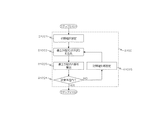
図1は、本実施形態の算出システムの構成図である。
(First embodiment)
FIG. 1 is a configuration diagram of a calculation system according to the present embodiment.
図1に示す算出システムは、電池装置20の残容量の算出を行うコンピュータシステムである。本実施形態において、算出システムの構成要素の一つである算出装置10は、処理機能に応じて装置をLAN、イントラネット等の通信ネットワークを介して組み合わせた算出装置群で構成することができる。
The calculation system shown in FIG. 1 is a computer system that calculates the remaining capacity of the
算出装置10は、CPU100と、RAM(RWM)110と、通信IF120と、入力IF131と、表示IF141と、ROM150と、記憶部160と、タイマ170を含む構成である。その他、USBメモリ等の外部記憶装置を装着するIF(インターフェース)を備えていてもよい。算出装置10は、プログラムを実行し演算するコンピュータである。
The
算出装置10は、通信IF120を解して二次電池装置20から電流値、電圧値などのデータを収集し、収集したデータを用いて各種演算処理を行う。
The
CPU100は、ROM150に予め書き込んだ各プログラムをRAM110に読み出し、算出処理を行う演算処理部(マイクロプロセッサ)である。CPU100は、機能に合わせて複数のCPU群(マイクロコンピュータ、マイクロコントローラ)で構成することができる。またCPU内にRAM機能をもった内蔵メモリを備えていてもよい。 The CPU 100 is an arithmetic processing unit (microprocessor) that reads each program written in advance in the ROM 150 into the RAM 110 and performs calculation processing. The CPU 100 can be configured by a plurality of CPU groups (microcomputers, microcontrollers) in accordance with functions. Further, a built-in memory having a RAM function may be provided in the CPU.
RAM(RWM)110は、CPU100がプログラムを実行するに際して使用する記憶エリアであって、ワーキングエリアとして用いられるメモリである。処理に必要なデータを一次記憶させるのに好適である。 A RAM (RWM) 110 is a storage area used when the CPU 100 executes a program, and is a memory used as a working area. It is suitable for temporarily storing data necessary for processing.
通信IF120は、二次電池装置とデータ授受を行う通信装置、通信手段である。たとえば、ルーターがある。本実施形態では通信IF20と二次電池装置20との接続は有線通信のごとく記載しているが、各種無線通信網に代替することができる。また、通信IF20と二次電池装置20との接続は一方向または双方向通信可能台数なネットワークを介して行われる形態であってもよい。
The communication IF 120 is a communication device and a communication unit that exchange data with the secondary battery device. For example, there is a router. In the present embodiment, the connection between the
入力IF130は、入力部131と算出装置10とを接続するインターフェースである。入力部131から送られてきた入力信号を変換しCPU100が認識可能な信号に変換する入力制御機能を有していても良い。本IFは端子等として必須の構成要素ではなく直接算出装置内の配線と接続されていてもよい。
The input IF 130 is an interface that connects the input unit 131 and the
入力部131は、コンピュータ装置が一般に備えている各種キーボードやボタン等の入力制御を行う入力装置、入力手段である。その他、人の発する声を認識することにより、入力信号として認識または検出する機能を備えていてもよい。本実施形態では算出装置10の外部に設置しているが算出装置に組み込まれていている形態であってもよい。
The input unit 131 is an input device or an input unit that performs input control of various keyboards and buttons that are generally provided in a computer device. In addition, a function of recognizing or detecting an input signal by recognizing a voice uttered by a person may be provided. In the present embodiment, it is installed outside the
表示IF140は、表示部141と算出装置10とを接続するインターフェースである。CPU100から表示IF141を介して表示部130の表示制御がおこなわれてもよいし、グラフィックボードなど描画処理を行うLSI(GPU)により表示制御が行われてもよい。表示制御機能として例えば、画像データを復号化するデコード機能がある。IFを使用せず算出装置10内部に直接接続される形態であってもよい。
The display IF 140 is an interface that connects the
表示部141は、液晶ディスプレイ、有機ELディスプレイ、プラズマディスプレイなどの出力装置、出力手段である。その他、音を発する機能を備えていてもよい。本実施形態では算出装置10の外部に設置しているが算出装置10の内部に組み込まれていてもよい。
The
ROM150は、回帰計算プログラム151と、劣化度算出プログラム152と、を格納するプログラムメモリである。データの書き込みはできない非一次記憶媒体を用いることが好適であるが、データの読み出し、書き込みが随時できる半導体メモリ等の記憶媒体であってもよい。その他、画像データを表示部141にて人が認識可能な文字や図柄を表示させる表示プログラムや、電池の劣化情報等のコンテンツを通信IF120を介して端末30に配信させるプログラム、取得したデータを記憶部160に予め定められた時間毎に記憶させる情報登録プログラムなどが格納されていてもよい。
The ROM 150 is a program memory that stores a regression calculation program 151 and a deterioration degree calculation program 152. A non-primary storage medium that cannot write data is preferably used, but a storage medium such as a semiconductor memory that can read and write data at any time may be used. In addition, a display program that displays characters and symbols that can be recognized by a person on the
回帰計算プログラム151は、電池装置20を構成する各電池セルごとまたは組電池毎の正極、負局の容量値、内部抵抗値を算出する機能をCPU100に実現させる手段である。例えば、以下の七つの値、(1)正極を構成する活物質Aの容量、(2)正極を構成する活物質Bの容量、(3)負極の容量、(4)正極を構成する活物質Aの充電量、(5)正極を構成する活物質Bの充電量、(6)負極の充電量、(7)内部抵抗値、を算出(解析)する。

これらの値を用いて、時間に対する充電電圧の変化特性、充電量に対する正極の電位およびまたは充電量に対する負極の電位特性を算出する。具体的動作については後述する。 Using these values, the change characteristic of the charge voltage with respect to time, the potential of the positive electrode with respect to the charge amount, and the potential characteristic of the negative electrode with respect to the charge amount are calculated. Specific operations will be described later.
回帰計算プログラム151は以下の各数式に対応するプログラム群により構成されている。なお、各プログラムの順番については、各種変更が可能である。 The regression calculation program 151 is composed of a program group corresponding to the following formulas. Various changes can be made to the order of the programs.
充電電圧VCは、電池の起電圧Ve,内部抵抗による電圧VRを用いて次の数式2
VC=Ve+VR (数式2)
から求める。
Charging voltage V C, the
V C = V e + V R (Formula 2)
Ask from.
電池の起電圧VEは、正極の電位Ec、負極の電位Eaを用いて次の数式3
Ve=Ec−Ea (数式3)
から求める。
Electromotive voltage V E of the battery, the following Equation 3 using the potential of the positive electrode Ec, the potential Ea of the negative electrode
V e = E c −E a (Formula 3)
Ask from.
正極と負極の電位は、充電量(q)、初期状態での正極の容量Qic、初期状態での負極の容量Qiaを用いて数式4、数式5
Ec=fc(q/Qic) (数式4)
Ea=fa(q/Qia) (数式5)
から求める。
The potentials of the positive electrode and the negative electrode are expressed by Equations 4 and 5 using the charged amount (q), the positive electrode capacity Q ic in the initial state, and the negative electrode capacity Q ia in the initial state.
E c = f c (q / Q ic ) (Formula 4)
E a = f a (q / Q ia ) (Formula 5)
Ask from.
ここで、複数の活物質で正極または負極を構成する場合について説明する。この場合、図3に示すように、それぞれの活物質の起電力は異なる特性を示す。活物質A(例えば、マンガン酸リチウム)と活物質B(例えば、コバルト酸リチウム)を混合した複合正極の起電圧の充電量に対する特性を算出する。算出した特性を図示すると図4のようになる。 Here, the case where a positive electrode or a negative electrode is comprised with a some active material is demonstrated. In this case, as shown in FIG. 3, the electromotive force of each active material exhibits different characteristics. The characteristic with respect to the charge amount of the electromotive force of the composite positive electrode in which the active material A (for example, lithium manganate) and the active material B (for example, lithium cobaltate) are mixed is calculated. The calculated characteristics are shown in FIG.
活物質Aの正極の電位EcA、活物質Bの正極の電位EcBが、初期状態の活物質Aの容量QicAと、初期状態の活物質Bの容量QicB、活物質Aの充電量qA、活物質Bの充電量qBとを用いて数式6、数式7、8、9
EcA=fcA(qA/QicA) (数式6)
EcB=fcB(qB/QicB) (数式7)
fcA(qA/QcA)=fcB(qB/QcB) (数式8)
q=qA+qB (数式9)
の関係にある(図3)。
The positive electrode potential E cA of the active material A, the positive electrode potential E cB of the active material B, the capacity Q icA of the active material A in the initial state, the capacity Q icB of the active material B in the initial state, and the charge amount of the active material A q a, equation 6 by using the charge amount q B of the active material B, equation 7,8,9
E cA = f cA (q A / Q icA ) (Formula 6)
E cB = f cB (q B / Q icB ) (Formula 7)
f cA (q A / Q cA ) = f cB (q B / Q cB ) (Formula 8)
q = q A + q B (Formula 9)
(FIG. 3).
よって、混合正極の電位Ecは、活物質Aの正極の充電開始時の容量qA、活物質Aの正極の充電量QcAまたは活物質Bの正極の充電開始時の容量qB、活物質Bの正極の充電量QcB用いて数式10
Ec=fc(q/Qic)=fcA(qA/QcA)=fcB(qB/QcB) (数式10)
から求める。
Therefore, the potential E c of the mixed positive electrode is determined by the capacity q A at the start of charging the positive electrode of the active material A, the charge amount Q cA of the positive electrode of the active material A or the capacity q B at the start of charging of the positive electrode of the active material B , Using the charge amount Q cB of the positive electrode of the substance B,
E c = f c (q / Q ic ) = f cA (q A / Q cA ) = fcB (q B / Q cB ) (Formula 10)
Ask from.
なお、活物質Aの正極の電位EcAと活物質Bの充電量qBは、各活物質表面の電位である。したがって、活物質内でのリチウムイオンの拡散抵抗により活物質内でのリチウムイオンの分布が変わるので充電電流により充電量と起電圧の関係が変わってしまうようにも思われる。しかしながら、本実施形態では、正極に使われる活物質や負極に使われる炭素系の活物質では、活物質内の拡散抵抗が小さいため、充電電流が変化しても、充電電流と起電圧の関係が大きくは変わらないものとして取扱っている。 Note that the positive electrode potential E cA of the active material A and the charge amount q B of the active material B are the potential of the surface of each active material. Therefore, the lithium ion distribution in the active material changes due to the diffusion resistance of lithium ions in the active material, so that it seems that the relationship between the charge amount and the electromotive voltage is changed by the charging current. However, in the present embodiment, the active material used for the positive electrode and the carbon-based active material used for the negative electrode have a small diffusion resistance in the active material, and therefore the relationship between the charging current and the electromotive voltage even if the charging current changes. Is treated as something that does not change significantly.
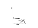
一方、負極に活物質としてチタン酸リチウムのような拡散抵抗の大きな材料を負極に用いた場合には、図5に示すように電流値によって充電量と起電圧の関係が大きく変化するため正極と同様の近似は行わない。 On the other hand, when a material having a large diffusion resistance, such as lithium titanate, is used for the negative electrode as the active material, the relationship between the charge amount and the electromotive voltage varies greatly depending on the current value as shown in FIG. A similar approximation is not performed.
よって、負極電位Eaは、数式11
Ea=fa(q/Qia,I/Qia) (数式11)
であらわされる。
Therefore, the negative electrode potential Ea is expressed by Equation 11.
E a = f a (q / Q ia , I / Q ia ) (Formula 11)
It is expressed.
また、内部抵抗による電圧VRは、充電電流Iと内部抵抗R(q)を用いて数式12、13
VR=R(q)×I (数式12)
q=∫Idt (数式13)
より求められる。
Further, the voltage V R due to the internal resistance, the formula using the charging current I and the internal resistance R (q) 12, 13
V R = R (q) × I (Formula 12)
q = ∫Idt (Formula 13)
More demanded.
つまり、数式2は、
Vc=fc(q/Qic)−fa(q/Qia,I/Qia)+R(q)×I
(数式2A)
としてあらわされる。
In other words,
Vc = fc (q / Qic) −fa (q / Qia, I / Qia) + R (q) × I
(Formula 2A)
It is expressed as.
このように、充電電圧と、活物質の起電圧特性及び内部抵抗とには非線形の相関関係がある。これから、活物質の容量、内部抵抗を変数として充電電圧の充電量に対する特性カーブについて回帰計算を行い、活物質の容量、内部抵抗を算出、決定する。 Thus, there is a non-linear correlation between the charging voltage, the electromotive voltage characteristic of the active material, and the internal resistance. From this, a regression calculation is performed on the characteristic curve of the charge voltage with respect to the charge amount using the capacity and internal resistance of the active material as variables, and the capacity and internal resistance of the active material are calculated and determined.
劣化度算出プログラム152は、回帰計算プログラム151を実行することにより求めた活物質の容量と内部抵抗の値から電池装置20の劣化度を算出する機能をCPU100に実現させる手段である。
The deterioration degree calculation program 152 is a means for causing the CPU 100 to realize a function of calculating the deterioration degree of the
各活物質の容量と内部抵抗を変数とし、劣化度を求める関数を関数情報DB163に記憶させておき、関数情報DB163から関数を読み出し本プログラムにより得られた各活物質の容量と内部抵抗とを比較して劣化度を算出する。 Using the capacity and internal resistance of each active material as variables, the function for obtaining the degree of deterioration is stored in the function information DB 163, the function is read from the function information DB 163, and the capacity and internal resistance of each active material obtained by this program are calculated. The degree of deterioration is calculated by comparison.
例えば、容量と内部抵抗の基準値を記憶しておき、本プログラムにより得られた容量または内部抵抗の値が基準値より小さくなった場合に、使用できない程度に劣化していると判断したり、使用用途によっては、容量と内部抵抗値から演算される劣化指標の演算方法(関数)を記憶しておき、本プログラムにより得られた容量と内部抵抗を用いて演算した劣化指標を劣化度として提示することもできる。 For example, the reference value of the capacity and the internal resistance is stored, and when the value of the capacity or the internal resistance obtained by this program becomes smaller than the reference value, it is judged that the deterioration is not possible. Depending on the application, the calculation method (function) of the deterioration index calculated from the capacity and internal resistance value is stored, and the deterioration index calculated using the capacity and internal resistance obtained by this program is presented as the degree of deterioration. You can also
記憶部160は、ハードディスクドライブ(HDD)などの不揮発性の記憶装置、記憶手段である。この他、不揮発性の記憶手段に限られることなくフラッシュメモリなどの半導体メモリを利用してもよいし、これらの半導体メモリと、HDDとを組み合わせた形態の記憶媒体であってもよい。本実施形態では、ROM150と記憶部160とは別の記憶媒体のごとく記載しているが、ROMと記憶部を併せて一の記憶部、記憶手段としてもよい。 The storage unit 160 is a non-volatile storage device such as a hard disk drive (HDD) or storage means. In addition, a semiconductor memory such as a flash memory may be used without being limited to the nonvolatile storage unit, or a storage medium in which these semiconductor memory and HDD are combined may be used. In the present embodiment, the ROM 150 and the storage unit 160 are described as different storage media, but the ROM and the storage unit may be combined into one storage unit and storage unit.
記憶部160は、計測値DB161と、算出結果DB162、関数情報DB163を格納している。その他、CPU100の算出処理に必要なデータが記憶されている。 The storage unit 160 stores a measurement value DB 161, a calculation result DB 162, and a function information DB 163. In addition, data necessary for the calculation process of the CPU 100 is stored.
測定結果DB161は、計測した電池装置20の電流値、電圧値などの測定データを予め定められた測定間隔毎にデータを記憶している。例えば、格納されたデータをテーブル形式で格納する。図示すると図6に示すような図を描く。格納された測定結果に関するデータは、回帰計算プログラム151を実行する際に利用される。
The measurement result DB 161 stores measurement data such as measured current values and voltage values of the
算出結果DB162は、回帰計算プログラム151を実行するCPU100によって算出された値を格納する。格納した値は、CPU100により読み出され表示IF140を介して表示部141に表示してもよい。本記憶手段に代えて、クラウドコンピューティングシステム内の算出装置10外部の記憶媒体に格納する形態であってもよい。
The calculation result DB 162 stores values calculated by the CPU 100 that executes the regression calculation program 151. The stored value may be read by the CPU 100 and displayed on the
また、関数情報DB163は、図4に示すように正極電位と充電量の関係を表す関数や、図5に示す負極電位と充電量との関係を示す関数、値を格納している。これらは、図5に示す負極電位と充電量との関係は、電流値の増大によって充電量に対する負極電位が一定となる領域が少なくなることをあらわしている。本関数情報は、正極、負極の劣化度を評価する際に利用される。 Further, the function information DB 163 stores a function representing the relationship between the positive electrode potential and the charge amount as shown in FIG. 4, and a function and value representing the relationship between the negative electrode potential and the charge amount shown in FIG. These indicate that the relationship between the negative electrode potential and the charge amount shown in FIG. 5 decreases the region where the negative electrode potential with respect to the charge amount becomes constant as the current value increases. This function information is used when evaluating the degree of deterioration of the positive electrode and the negative electrode.
また、正極、負極の充電量に対する電位を求める際のデータも格納されている。正極または負極が複数の材料で構成されている場合は、各材料ごとに対応する関数が格納されている。 In addition, data for obtaining the potential with respect to the charge amount of the positive electrode and the negative electrode is also stored. When the positive electrode or the negative electrode is composed of a plurality of materials, a function corresponding to each material is stored.
タイマ170は、時間を計測するための時計である。計測した時刻を利用してCPU100は、電流値、電圧値の計測、格納を行う。算出装置10は、タイマ170に代えて、ネットワークを介して時間を取得する形態であってもよいし、タイマ170による計測とネットワークから得られる時刻とから時刻を算出する形態であってもよい。
The
電池装置20は、電池と電池の電流値、電圧値等を計測する制御回路を備えた装置である。電池には、各種二次電池が利用できる。例えば、VTM21により電圧検出がなされ、電圧検出回路602により電圧が検出される。
The
端末30は上記電池装置20を積んだ車両や定置形電池装置である。CPU300と、RAM(RWM)310と、通信IF320と、入力IF331と、表示IF341と、ROM350と、記憶部360と、タイマ370と蓄電池380とを含む構成である。なお、蓄電池に充電を行う充電器381、モータ383に蓄電池から電力を送る際に直流−交流変換を行うインバータ382を備えていても良い。また、端末30内を制御するCPU100に代えてプログラマブルコントローラ385を使用しても良い。
The terminal 30 is a vehicle or a stationary battery device loaded with the
各構成要素の機能は、算出装置の各構成要素と同様なので省略する。なお、CPU100とCPU300によって各プログラムの実行を分割して実行してもよい。蓄電池380は電池装置20である。
Since the function of each component is the same as that of each component of the calculation apparatus, a description thereof will be omitted. The execution of each program may be divided and executed by CPU 100 and CPU 300. The storage battery 380 is the
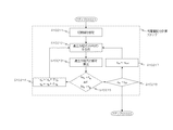
次に具体的な動作の一例について図7、図8を主に参照しながら説明する。 Next, an example of a specific operation will be described with reference mainly to FIGS.
充電電流値は、簡単のため定電流充電の場合について記載している。充電電流値は、一定値である必要はないが、測定誤差や計算誤差の少なさから定電流充電での測定が好適である。 The charging current value is described for the case of constant current charging for simplicity. The charging current value does not need to be a constant value, but measurement with constant current charging is preferable because of small measurement errors and calculation errors.
また、内部抵抗値は充電量qに対して変化しないものとして取り扱う。 Further, the internal resistance value is handled as not changing with respect to the charge amount q.
また、本実施形態では、各セルごとに電圧を測定した場合について記載する。組電池のように複数のセルを有する電池モジュールに対して本算出方法を用いる場合には、各セルごとに劣化の進行状況も異なることから充電電圧の時間変化をセル毎に測定することが好適である。(ステップS101)。 Moreover, in this embodiment, it describes about the case where a voltage is measured for every cell. When this calculation method is used for a battery module having a plurality of cells such as an assembled battery, it is preferable to measure the time change of the charging voltage for each cell because the progress of deterioration differs for each cell. It is. (Step S101).
このようにし測定した充電電圧を測定結果DB161に格納する。充電開始から充電終止電圧到達までの充電時間tcの間にN個の測定値が得られた。充電直後は、過渡期で充電電圧が安定していないため、この過渡期tsの期間に得られたns個のデータは活物質の容量や、内部抵抗を算出するための回帰計算に用いていない。 The measured charging voltage is stored in the measurement result DB 161. N measurement values were obtained during the charging time t c from the start of charging until the end of charging voltage was reached. Immediately after charging, the charging voltage is not stable in the transition period, so the ns data obtained during this transition period ts is not used for the regression calculation to calculate the capacity of the active material and the internal resistance. .
算出装置10は、各セルの充電電圧の測定値を取得する。取得した値をRAM110に一時格納または、記憶部160に記憶させる。
The
CPU100はROM150から回帰計算プログラム151を実行し、非線形微分方程式の解を回帰計算により解析する(ステップS102)。 The CPU 100 executes the regression calculation program 151 from the ROM 150, and analyzes the solution of the nonlinear differential equation by regression calculation (step S102).
定電流充電を行っているので充電開始からの充電量qcは、数式13から
qc=I・t
求める。
Since constant current charging is performed, the charge amount q c from the start of charging can be calculated from Equation 13 as follows: q c = I · t
Ask.
このように充電量qに対応した測定電圧、測定値(V1,qc1)、(V2,qc2),………,(VN,qcN)を得る。 In this way, the measurement voltage and the measurement values (V 1 , q c1 ), (V 2 , q c2 ),..., (V N , q cN ) corresponding to the charge amount q are obtained.
得た値を、CPU100は、RAM110に一時格納または、記憶部160に記憶させる。 The CPU 100 temporarily stores the obtained value in the RAM 110 or stores it in the storage unit 160.
上記測定値を用いて回帰計算を行う。回帰計算を行う際に使用する残差平方和は、下式で表される。
充電開始時の充電量は回帰計算時には未知数であることから、上記充電開始時の正極および負極の充電量も未知数となる。 Since the charge amount at the start of charging is an unknown number at the time of regression calculation, the charge amounts of the positive electrode and the negative electrode at the start of charging are also unknown.
本実施形態では、正極が活物質Aと活物質Bの複合正極の場合には、回帰計算の未知数は、
である。 It is.
よって、次の連立方程式の解を求める(ステップS1022)。
初期値としては、適当な値、例えば、前回測定時の値を用いる(ステップS1021)。
次のステップの各値は次式で求められる(ステップS1023)。
このとき、
は、次式を解いて得られる。本実施形態では、ニュートン法を用いて説明しているが、これに代えてレーベンバーグ、マルカート法などの他の数値解析法を用いても良い。
求めた値が以下の収束条件(収束半径)
を満たすまで繰り返し演算する(ステップS1024、ステップS1025)。このようにして繰り返し演算した結果が記憶部160に格納される(ステップS103)。 The calculation is repeated until the condition is satisfied (steps S1024 and S1025). The result of repeated calculations in this way is stored in the storage unit 160 (step S103).
次にCPU100は、次に劣化度算出プログラム152を実行する。 Next, the CPU 100 executes the deterioration degree calculation program 152 next.
上記回帰計算プログラム151により算出された容量や内部抵抗と、予め記憶されている劣化基準との比較、または、予め記憶されている演算方法(関数)により容量と内部抵抗を用いて劣化度を算出する(ステップS104)。 Comparing the capacity and internal resistance calculated by the regression calculation program 151 with a deterioration criterion stored in advance, or calculating the degree of deterioration using the capacity and internal resistance by a pre-stored calculation method (function) (Step S104).
CPU100は、算出した結果を、表示プログラムなどの表示制御手段を実行し表示部141に表示する。
The CPU 100 displays the calculated result on the
なお、ステップ102で演算処理された充電電圧と内部抵抗をそのまま表示部141に表示させる形態であってもよい。
In addition, the form which displays the charging voltage and internal resistance which were arithmetic-processed at step 102 on the
次にステップS1022の演算処理について、例示する。 Next, the calculation process in step S1022 will be exemplified.
第一に、正極または負極が単極の場合、例えば数式27の第3列第3行についてとくと、
となり、微分を小変異ΔQcを用いて計算して、
となる。 It becomes.
同様に第1行第7列の数式について計算すると、
としてあらわせる。 As shown.
他の項についても同様に計算がなされる。 The other terms are similarly calculated.
次に正極が複合材の場合のステップS1022の演算の前処理について、図10を用いて説明する。 Next, the pre-processing of the calculation in step S1022 when the positive electrode is a composite material will be described with reference to FIG.
まず初期値を設定する(ステップS10211)。 First, an initial value is set (step S10211).
qcn← qc ns+1、qA, qB
次に、qA、qBに連立方程式を生成し、解を求める(ステップS10212、S10213)。
Next, simultaneous equations are generated for q A and q B to find a solution (steps S10212 and S10213).
次に予め定めた収束半径内に解が入るか否かを判定する(ステップS10214)。
入っていない場合、新たな初期値を設定し、qA, qBを求める(ステップS10215)。 If not, new initial values are set, and q A and q B are obtained (step S10215).
入っている場合(ステップS10214−YES)は、次の測定点についての算出を行う(ステップS10216、S10217)。 If it is present (step S10214—YES), the calculation for the next measurement point is performed (steps S10216, S10217).
得られる解が次の式で表される。
ここで、正極電圧は、
でもとめられる。 But you can stop.
この数列は
![]()
![]()
のように記載できる。 It can be described as follows.
すると、∂2S/∂QcAについて例示すると
となる。他の正極に関係する項についても同様に求めることができる。 It becomes. The terms related to other positive electrodes can be similarly obtained.
このように本実施形態によれば、正極の電位、負極の電位、充電電圧を算出することができる。 Thus, according to this embodiment, the positive electrode potential, the negative electrode potential, and the charging voltage can be calculated.
このように正極の電池、負極の電位をより精密に求めることにより、充電電圧のみを用いた劣化判断ではできなかった正極、負極のみが劣化が進んでいる場合を検出することができることから、より正確な劣化判定を行うことができる。 In this way, by more accurately determining the potential of the positive electrode battery and the negative electrode, it is possible to detect the case where only the positive electrode and the negative electrode that are not able to be judged by the deterioration judgment using only the charging voltage are progressing. Accurate deterioration determination can be performed.
さらに、電池の特性に応じて一部の値を一定とすることにより処理の高速化も実現することができる。 Furthermore, the processing speed can be increased by keeping some values constant according to the characteristics of the battery.
<変形例>
第1の実施形態の変形例について、図10乃至図14を参照しながら説明する。
<Modification>
A modification of the first embodiment will be described with reference to FIGS. 10 to 14.
図10、11では、端末30内に算出装置10を備えている。この場合、上位側にサーバを設ける必要がなく、通信ネットワーク1の情報通信量の低減を実行することができる。
10 and 11, the
図12では、算出機関がインターネットおよび通信機を通じて端末30の情報を集め算出装置10にて電池状態を評価する実施形態である。データの一元管理が可能であり、電池状態の評価をより正確に行うことができる。また、信頼性の保持にも役立つ。
FIG. 12 shows an embodiment in which the calculation organization collects information of the terminal 30 through the Internet and a communication device and evaluates the battery state in the
図13では、無線通信にて端末30からの電池情報の収集を行う。一定時間毎に行うことができ電池特性の算出に好適である。 In FIG. 13, battery information is collected from the terminal 30 by wireless communication. This can be performed at regular intervals and is suitable for calculating battery characteristics.
図14では、急速充電器などの充電器にて算出装置10を備えている実施形態である。
In FIG. 14, it is embodiment which is provided with the
以上、本発明のいくつかの実施形態を説明したが、これらの実施形態は、例として提示したものであり、発明の範囲を限定することは意図していない。これら新規な実施形態は、その他の様々な形態で実施されることが可能であり、発明の要旨を逸脱しない範囲で、種々の省略、置き換え、変更を行うことができる。例えば、正極、負極を構成する物質は、2種類に限られることなく、1種類、3種類以上であってもよい。これら実施形態やその変形は、発明の範囲や要旨に含まれるとともに、特許請求の範囲に記載された発明とその均等の範囲に含まれる。
以下、本出願当初の特許請求の範囲の記載を付記する。
[1]
電池電圧を算出する算出装置に
電池の充電量とそのときに発生している電池電圧とを対応させて記憶する測定値データベースと、電池内に含まれる複数の活物質の充電量と電圧の関係を表す関数を記憶する関数情報データベースと、を参照して前記関数情報データベースに格納された関数の活物質の量を変数として前記測定値データベースに記憶された電池電圧を回帰計算する演算機能
を実現させる算出方法。
[2]
前記演算機能は、
前記電池の内部抵抗値と、充電電流値から求める前記電池の充電開始からの測定時までの充電量とを変数として前記電池の充電電圧の時間特性を算出する
[1]に記載する算出方法。
[3]
前演算機能は、
活物質の充電量の変化量を変数として前記電池の充電電圧の時間特性を算出する
[1]または[2]に記載する算出方法。
[4]
前記充電電流値は定電流充電時の電流値である
[1]乃至[3]のうちいずれかに記載する算出方法。
[5]
前記電池は、
複数の活物質を含む正極およびまたは複数の活物質を含む負極を備え、
前記演算機能は、
前記活物質の電位−充電量特性を格納する関数情報データベースを参照して前記複数の活物質を含む正極の正極電圧およびまたは前記複数の活物質を含む負極の負極電圧を算出する
[1]乃至[4]いずれかに記載する算出方法。
[6]
ROMからデータを読み出し算出処理を行うCPUを備えるコンピュータに電池の劣化度を算出させる算出プログラムであって、
前記CPUに、
電池の充電量とそのときに発生している電池電圧とを対応させて記憶する測定値データベースと、電池内に含まれる複数の活物質の充電量と電圧の関係を表す関数を記憶する関数情報データベースと、を参照して前記関数情報データベースに格納された関数の活物質の量を変数として前記測定値データベースに記憶された電池電圧を回帰計算する演算機能
を実現させる算出プログラム。
[7]
電池の充電量とそのときに発生している電池電圧とを対応させて記憶する測定値データベースと、電池内に含まれる複数の活物質の充電量と電圧の関係を表す関数を記憶する関数情報データベースと、を参照して前記関数情報データベースに格納された関数の活物質の量を変数として前記測定値データベースに記憶された電池電圧を回帰計算する演算手段
を備えた算出システム。
[8]
電池の充電量とそのときに発生している電池電圧とを対応させて記憶する測定値データベースと、電池内に含まれる複数の活物質の充電量と電圧の関係を表す関数を記憶する関数情報データベースと、を参照して前記関数情報データベースに格納された関数の活物質の量を変数として前記測定値データベースに記憶された電池電圧を回帰計算する演算手段
を備えた算出装置。
As mentioned above, although some embodiment of this invention was described, these embodiment is shown as an example and is not intending limiting the range of invention. These novel embodiments can be implemented in various other forms, and various omissions, replacements, and changes can be made without departing from the scope of the invention. For example, the materials constituting the positive electrode and the negative electrode are not limited to two types, and may be one type, three types or more. These embodiments and modifications thereof are included in the scope and gist of the invention, and are included in the invention described in the claims and the equivalents thereof.
Hereinafter, the description of the scope of claims at the beginning of the present application will be added.
[1]
For a calculation device that calculates battery voltage
A measurement value database that stores the amount of charge of a battery in association with the battery voltage generated at that time, and function information that stores a function that represents the relationship between the amount of charge and voltage of a plurality of active materials contained in the battery A calculation function for regression calculation of the battery voltage stored in the measurement value database with the amount of the active material of the function stored in the function information database as a variable
A calculation method that realizes
[2]
The calculation function is
The time characteristic of the charging voltage of the battery is calculated using the internal resistance value of the battery and the amount of charge from the start of charging of the battery to the time of measurement obtained from the charging current value as variables.
The calculation method described in [1].
[3]
Pre-calculation function
The time characteristic of the charging voltage of the battery is calculated using the amount of change in the charge amount of the active material as a variable
The calculation method described in [1] or [2].
[4]
The charging current value is a current value during constant current charging.
The calculation method according to any one of [1] to [3].
[5]
The battery is
Comprising a positive electrode comprising a plurality of active materials and / or a negative electrode comprising a plurality of active materials,
The calculation function is
The positive voltage of the positive electrode including the plurality of active materials and the negative voltage of the negative electrode including the plurality of active materials are calculated with reference to a function information database storing the potential-charge amount characteristics of the active material.
The calculation method according to any one of [1] to [4].
[6]
A calculation program for causing a computer including a CPU to read data from a ROM and perform calculation processing to calculate the degree of battery deterioration,
In the CPU,
A measurement value database that stores the amount of charge of a battery in association with the battery voltage generated at that time, and function information that stores a function that represents the relationship between the amount of charge and voltage of a plurality of active materials contained in the battery A calculation function for regression calculation of the battery voltage stored in the measurement value database with the amount of the active material of the function stored in the function information database as a variable
A calculation program that realizes
[7]
A measurement value database that stores the amount of charge of a battery in association with the battery voltage generated at that time, and function information that stores a function that represents the relationship between the amount of charge and voltage of a plurality of active materials contained in the battery And a calculation means for performing regression calculation of the battery voltage stored in the measurement value database with the amount of the active material of the function stored in the function information database as a variable with reference to the database
Calculation system with
[8]
A measurement value database that stores the amount of charge of a battery in association with the battery voltage generated at that time, and function information that stores a function that represents the relationship between the amount of charge and voltage of a plurality of active materials contained in the battery And a calculation means for performing regression calculation of the battery voltage stored in the measurement value database with the amount of the active material of the function stored in the function information database as a variable with reference to the database
A calculation device comprising:
1 … 通信ネットワーク
10 … 算出装置
20 … 電池装置
30 … 端末
100、300 … CPU(Central Processing Unit)(算出処理部)
110、310 … RAM(RWM)(Random Access Memory)(Read Write Memory)
120、320 … 通信IF(inter face)
130、330 … 入力部
131、331 … 入力IF
140、340 … 表示部
141、341 … 表示IF
150、350 … ROM(Read Only Memory)
151 … 回帰計算プログラム
152 … 劣化度算出プログラム
160、360 … 記憶部
161 … 測定結果DB(data base)
162 … 算出結果DB
163 … 関数情報DB
170、370 … タイマ
DESCRIPTION OF SYMBOLS 1 ...
110, 310 ... RAM (RWM) (Random Access Memory) (Read Write Memory)
120, 320 ... Communication IF (inter face)
130, 330 ... input units 131, 331 ... input IF
140, 340 ...
150, 350 ... ROM (Read Only Memory)
151 ... Regression calculation program 152 ... Deterioration degree calculation program 160, 360 ... Storage unit 161 ... Measurement result DB (data base)
162 ... Calculation result DB
163 ... Function information DB
170, 370 ... Timer
Claims (1)
前記電池内に含まれる複数の活物質の充電量と前記充電電圧値との関係を表す関数を記憶する関数情報データベースと、
前記関数情報データベースに記憶された関数における正極活物質の容量、負極活物質の容量、正極活物質の充電量、負極活物質の充電量、及び抵抗を変数として前記測定値データベースに記憶されている前記充電電圧値を回帰計算することにより、これら変数の値を求め、これらのうち正極活物質の容量、負極活物質の容量、及び抵抗に基づき前記電池の正極の劣化度、及び負極の劣化度を算出する演算手段と、を有する電池劣化算出装置。 A measured value database for storing a charging voltage value of a charged battery and a charge amount of the battery in association with each other;
A function information database for storing a function representing the relationship between the charge amount of a plurality of active materials contained in the battery and the charge voltage value;
The capacity value of the positive electrode active material, the capacity of the negative electrode active material, the charge amount of the positive electrode active material, the charge amount of the negative electrode active material, and the resistance in the function stored in the function information database are stored in the measurement value database as variables. By calculating the charge voltage value by regression, the values of these variables are obtained. Among these variables, the positive electrode active material capacity, the negative electrode active material capacity, and the resistance are determined based on the positive electrode deterioration degree and the negative electrode deterioration degree. And a battery deterioration calculating device.
Priority Applications (4)
| Application Number | Priority Date | Filing Date | Title |
|---|---|---|---|
| JP2011122965A JP5889548B2 (en) | 2011-05-31 | 2011-05-31 | Battery deterioration calculation device |
| US13/482,256 US9213070B2 (en) | 2011-05-31 | 2012-05-29 | Calculation method, calculation system, and calculation apparatus |
| EP12169994.6A EP2530482B1 (en) | 2011-05-31 | 2012-05-30 | Battery deterioration-calculation method and apparatus |
| CN201210176556.7A CN102983371B (en) | 2011-05-31 | 2012-05-31 | Calculation method, calculation system, and calculation device |
Applications Claiming Priority (1)
| Application Number | Priority Date | Filing Date | Title |
|---|---|---|---|
| JP2011122965A JP5889548B2 (en) | 2011-05-31 | 2011-05-31 | Battery deterioration calculation device |
Publications (2)
| Publication Number | Publication Date |
|---|---|
| JP2012251806A JP2012251806A (en) | 2012-12-20 |
| JP5889548B2 true JP5889548B2 (en) | 2016-03-22 |
Family
ID=46513626
Family Applications (1)
| Application Number | Title | Priority Date | Filing Date |
|---|---|---|---|
| JP2011122965A Active JP5889548B2 (en) | 2011-05-31 | 2011-05-31 | Battery deterioration calculation device |
Country Status (3)
| Country | Link |
|---|---|
| EP (1) | EP2530482B1 (en) |
| JP (1) | JP5889548B2 (en) |
| CN (1) | CN102983371B (en) |
Cited By (3)
| Publication number | Priority date | Publication date | Assignee | Title |
|---|---|---|---|---|
| US10938075B2 (en) | 2017-09-20 | 2021-03-02 | Kabushiki Kaisha Toshiba | Battery safety evaluation apparatus, battery control apparatus, battery safety evaluation method, non-transitory computer readable medium, control circuit, and power storage |
| EP4060598A1 (en) | 2021-03-15 | 2022-09-21 | Kabushiki Kaisha Toshiba | Information system and information providing method for storage battery |
| DE112020007490T5 (en) | 2020-08-04 | 2023-06-07 | Mitsubishi Electric Corporation | DEVICE FOR ESTIMATION OF THE INTERNAL CONDITION OF A STORAGE BATTERY AND METHOD OF ESTIMATION OF THE INTERNAL CONDITION OF A STORAGE BATTERY |
Families Citing this family (22)
| Publication number | Priority date | Publication date | Assignee | Title |
|---|---|---|---|---|
| JP6239241B2 (en) * | 2013-02-04 | 2017-11-29 | 株式会社東芝 | Battery performance estimation method and battery performance estimation apparatus |
| JP2014190763A (en) | 2013-03-26 | 2014-10-06 | Toshiba Corp | Battery lifetime estimation method and battery lifetime estimation device |
| US9742042B2 (en) * | 2013-11-23 | 2017-08-22 | Hrl Laboratories, Llc | Voltage protection and health monitoring of batteries with reference electrodes |
| JP6151163B2 (en) * | 2013-12-06 | 2017-06-21 | 株式会社東芝 | Battery state calculation device and battery state calculation method |
| JP6251091B2 (en) | 2014-03-17 | 2017-12-20 | 株式会社東芝 | Secondary battery internal state calculation device and secondary battery internal state calculation method |
| JP2015178963A (en) * | 2014-03-18 | 2015-10-08 | 株式会社東芝 | calculation apparatus and calculation method |
| JP6411538B2 (en) * | 2014-11-05 | 2018-10-24 | 東芝インフラシステムズ株式会社 | Prediction system, prediction program, prediction device |
| WO2017046870A1 (en) | 2015-09-15 | 2017-03-23 | 株式会社 東芝 | Storage battery control device, control method, program, power storage system, electric power system |
| JP2018046667A (en) | 2016-09-14 | 2018-03-22 | 株式会社東芝 | Charging pattern creation device, charging control device, charging pattern creation method, program, and power storage system |
| JP6567582B2 (en) | 2017-03-08 | 2019-08-28 | 株式会社東芝 | Charge / discharge control device, use condition creation device, program, and power storage system |
| JP6672351B2 (en) * | 2018-02-13 | 2020-03-25 | 株式会社東芝 | Calculation device and calculation method |
| CN108650322B (en) * | 2018-05-16 | 2020-10-16 | 北京小米移动软件有限公司 | Battery data processing method and device |
| JP6985998B2 (en) | 2018-09-12 | 2021-12-22 | 株式会社東芝 | Battery state estimation device, battery state estimation method, program, control circuit and power storage system |
| JP7039499B2 (en) * | 2019-01-04 | 2022-03-22 | 株式会社東芝 | Internal state estimation device and method, as well as battery control device |
| CN109895717B (en) * | 2019-01-30 | 2020-04-14 | 青岛海尔空调器有限总公司 | Parking air conditioner and service life early warning method and system of vehicle battery |
| WO2021044635A1 (en) | 2019-09-06 | 2021-03-11 | 株式会社 東芝 | Storage battery evaluation device, storage battery evaluation method and storage battery evaluation system |
| JP2021048663A (en) | 2019-09-17 | 2021-03-25 | 株式会社東芝 | Battery control device, charge/discharge system, parking lot system, secondary battery reuse system, battery control method, and battery control program |
| JP7191873B2 (en) | 2020-01-17 | 2022-12-19 | 株式会社東芝 | Charge/discharge control device, charge/discharge system, charge/discharge control method, and charge/discharge control program |
| JP7387660B2 (en) | 2021-02-10 | 2023-11-28 | 株式会社東芝 | Battery diagnostic method, battery diagnostic device, battery diagnostic system, battery-equipped equipment, and battery diagnostic program |
| JP2022139620A (en) | 2021-03-12 | 2022-09-26 | 株式会社東芝 | Battery diagnostic method, battery diagnostic device, battery diagnostic system, battery-equipped device, and battery diagnostic program |
| JP7395540B2 (en) | 2021-06-01 | 2023-12-11 | 株式会社東芝 | Battery deterioration determination method, battery deterioration determination device, battery management system, battery equipped equipment, and battery deterioration determination program |
| CN114062891A (en) * | 2021-10-11 | 2022-02-18 | 深圳市德斯戈智能科技有限公司 | Calculation force testing device based on AI chip |
Family Cites Families (16)
| Publication number | Priority date | Publication date | Assignee | Title |
|---|---|---|---|---|
| JP2000050507A (en) * | 1998-07-28 | 2000-02-18 | Ntt Power & Building Facilities Inc | Device for discriminating deterioration of storage battery and method of discriminating deterioration of storage battery |
| JP3470098B2 (en) * | 2000-11-28 | 2003-11-25 | 日本電信電話株式会社 | Lithium ion battery capacity estimation method, deterioration judgment method, deterioration judgment device, and lithium ion battery pack having deterioration judgment function |
| JP3743704B2 (en) * | 2000-09-25 | 2006-02-08 | Necトーキン栃木株式会社 | Battery pack |
| JP4107567B2 (en) * | 2002-04-18 | 2008-06-25 | 財団法人電力中央研究所 | Lithium-ion battery deterioration diagnosis method and apparatus incorporating the deterioration diagnosis method |
| JP2004063394A (en) * | 2002-07-31 | 2004-02-26 | Sanyo Electric Co Ltd | Nonaqueous electrolyte battery |
| JP5220269B2 (en) * | 2005-09-16 | 2013-06-26 | 古河電気工業株式会社 | Method and apparatus for detecting deterioration / charge state of storage battery |
| JP4788307B2 (en) * | 2005-11-17 | 2011-10-05 | 日産自動車株式会社 | Secondary battery input / output possible power estimation device |
| US8102152B2 (en) * | 2007-01-11 | 2012-01-24 | Panasonic Corporation | Deterioration detecting method and deterioration suppressing method for rechargeable lithium batteries, deterioration detector, deterioration suppressor, battery pack, and charger |
| JP4468387B2 (en) * | 2007-02-05 | 2010-05-26 | キヤノン株式会社 | Battery pack and electronic equipment |
| JP4884404B2 (en) * | 2007-09-07 | 2012-02-29 | 日立ビークルエナジー株式会社 | Method and apparatus for detecting internal information of secondary battery |
| JP4561859B2 (en) * | 2008-04-01 | 2010-10-13 | トヨタ自動車株式会社 | Secondary battery system |
| US8374807B2 (en) * | 2008-11-13 | 2013-02-12 | Lockheed Martin Corporation | Method and apparatus that detects state of charge (SOC) of a battery |
| JP4744622B2 (en) * | 2009-07-01 | 2011-08-10 | トヨタ自動車株式会社 | Vehicle control device |
| JP5493657B2 (en) * | 2009-09-30 | 2014-05-14 | 新神戸電機株式会社 | Storage battery device and battery state evaluation device and method for storage battery |
| JP5475385B2 (en) | 2009-09-30 | 2014-04-16 | 株式会社東芝 | Secondary battery characteristic evaluation apparatus, vehicle and charger |
| KR101338639B1 (en) * | 2010-06-07 | 2013-12-06 | 미쓰비시덴키 가부시키가이샤 | Charge status estimation apparatus |
-
2011
- 2011-05-31 JP JP2011122965A patent/JP5889548B2/en active Active
-
2012
- 2012-05-30 EP EP12169994.6A patent/EP2530482B1/en active Active
- 2012-05-31 CN CN201210176556.7A patent/CN102983371B/en active Active
Cited By (3)
| Publication number | Priority date | Publication date | Assignee | Title |
|---|---|---|---|---|
| US10938075B2 (en) | 2017-09-20 | 2021-03-02 | Kabushiki Kaisha Toshiba | Battery safety evaluation apparatus, battery control apparatus, battery safety evaluation method, non-transitory computer readable medium, control circuit, and power storage |
| DE112020007490T5 (en) | 2020-08-04 | 2023-06-07 | Mitsubishi Electric Corporation | DEVICE FOR ESTIMATION OF THE INTERNAL CONDITION OF A STORAGE BATTERY AND METHOD OF ESTIMATION OF THE INTERNAL CONDITION OF A STORAGE BATTERY |
| EP4060598A1 (en) | 2021-03-15 | 2022-09-21 | Kabushiki Kaisha Toshiba | Information system and information providing method for storage battery |
Also Published As
| Publication number | Publication date |
|---|---|
| EP2530482B1 (en) | 2024-03-20 |
| EP2530482A3 (en) | 2018-01-03 |
| CN102983371B (en) | 2015-04-15 |
| CN102983371A (en) | 2013-03-20 |
| EP2530482A2 (en) | 2012-12-05 |
| JP2012251806A (en) | 2012-12-20 |
Similar Documents
| Publication | Publication Date | Title |
|---|---|---|
| JP5889548B2 (en) | Battery deterioration calculation device | |
| US9213070B2 (en) | Calculation method, calculation system, and calculation apparatus | |
| JP6239241B2 (en) | Battery performance estimation method and battery performance estimation apparatus | |
| CN107690585B (en) | Method and apparatus for determining the state of health and state of charge of a lithium sulfur battery | |
| JP5349810B2 (en) | Storage device abnormality detection device, method, and program | |
| JP6004334B2 (en) | Battery system and battery system evaluation method | |
| JP5850492B2 (en) | Battery system and battery evaluation method | |
| JP5567956B2 (en) | Cell voltage equalization device for multiple assembled batteries | |
| JP6151163B2 (en) | Battery state calculation device and battery state calculation method | |
| WO2014156869A1 (en) | Battery life estimation method and battery life estimation device | |
| JP6324248B2 (en) | Battery state detection device, secondary battery system, battery state detection program, battery state detection method | |
| JP6376091B2 (en) | Battery power prediction device | |
| CN109991554B (en) | Battery electric quantity detection method and device and terminal equipment | |
| WO2016009756A1 (en) | Battery state detection device, secondary battery system, program product, and battery state detection method | |
| JP6110771B2 (en) | Deterioration amount calculation device, deterioration amount calculation method, and program | |
| CN112904208A (en) | Method and system for estimating open circuit voltage of battery cell | |
| CN103424708A (en) | Open circuit voltage estimation device, condition estimation device, and method of estimating open circuit voltage | |
| JP5583057B2 (en) | Battery module, battery pack system, battery adjustment method and program | |
| KR20220029109A (en) | Method and apparatus estimating a state of battery | |
| JPWO2016071941A1 (en) | Prediction system, prediction program, prediction device | |
| JPWO2015133401A1 (en) | Control unit, storage battery system, battery cell balance method and program | |
| KR101745633B1 (en) | Apparatus for Cell Balancing by Connecting Reference Battery in Consecutive Order and Method thereof | |
| JP6283952B2 (en) | Battery remaining amount detection device, battery system, battery remaining amount detection method, and program | |
| KR20150034593A (en) | Method and apparatus for state of charge estimation of battery | |
| Zhang et al. | Multiparameters model of the initial SOC considering the relaxation effect |
Legal Events
| Date | Code | Title | Description |
|---|---|---|---|
| A621 | Written request for application examination |
Free format text: JAPANESE INTERMEDIATE CODE: A621 Effective date: 20140417 |
|
| A977 | Report on retrieval |
Free format text: JAPANESE INTERMEDIATE CODE: A971007 Effective date: 20150122 |
|
| A131 | Notification of reasons for refusal |
Free format text: JAPANESE INTERMEDIATE CODE: A131 Effective date: 20150213 |
|
| RD02 | Notification of acceptance of power of attorney |
Free format text: JAPANESE INTERMEDIATE CODE: A7422 Effective date: 20150216 |
|
| RD04 | Notification of resignation of power of attorney |
Free format text: JAPANESE INTERMEDIATE CODE: A7424 Effective date: 20150218 |
|
| RD03 | Notification of appointment of power of attorney |
Free format text: JAPANESE INTERMEDIATE CODE: A7423 Effective date: 20150309 |
|
| A521 | Request for written amendment filed |
Free format text: JAPANESE INTERMEDIATE CODE: A821 Effective date: 20150309 |
|
| A521 | Request for written amendment filed |
Free format text: JAPANESE INTERMEDIATE CODE: A523 Effective date: 20150327 |
|
| A131 | Notification of reasons for refusal |
Free format text: JAPANESE INTERMEDIATE CODE: A131 Effective date: 20150908 |
|
| A521 | Request for written amendment filed |
Free format text: JAPANESE INTERMEDIATE CODE: A523 Effective date: 20151106 |
|
| TRDD | Decision of grant or rejection written | ||
| A01 | Written decision to grant a patent or to grant a registration (utility model) |
Free format text: JAPANESE INTERMEDIATE CODE: A01 Effective date: 20160119 |
|
| A61 | First payment of annual fees (during grant procedure) |
Free format text: JAPANESE INTERMEDIATE CODE: A61 Effective date: 20160217 |
|
| R151 | Written notification of patent or utility model registration |
Ref document number: 5889548 Country of ref document: JP Free format text: JAPANESE INTERMEDIATE CODE: R151 |