EP3794397B1 - Near-eye display having overlapping projector assemblies - Google Patents
Near-eye display having overlapping projector assemblies Download PDFInfo
- Publication number
- EP3794397B1 EP3794397B1 EP19804151.9A EP19804151A EP3794397B1 EP 3794397 B1 EP3794397 B1 EP 3794397B1 EP 19804151 A EP19804151 A EP 19804151A EP 3794397 B1 EP3794397 B1 EP 3794397B1
- Authority
- EP
- European Patent Office
- Prior art keywords
- image
- projector
- loe
- partial
- viewer
- Prior art date
- Legal status (The legal status is an assumption and is not a legal conclusion. Google has not performed a legal analysis and makes no representation as to the accuracy of the status listed.)
- Active
Links
Images


Classifications
-
- G—PHYSICS
- G02—OPTICS
- G02B—OPTICAL ELEMENTS, SYSTEMS OR APPARATUS
- G02B6/00—Light guides; Structural details of arrangements comprising light guides and other optical elements, e.g. couplings
-
- G—PHYSICS
- G02—OPTICS
- G02B—OPTICAL ELEMENTS, SYSTEMS OR APPARATUS
- G02B27/00—Optical systems or apparatus not provided for by any of the groups G02B1/00 - G02B26/00, G02B30/00
- G02B27/01—Head-up displays
- G02B27/017—Head mounted
-
- G—PHYSICS
- G02—OPTICS
- G02B—OPTICAL ELEMENTS, SYSTEMS OR APPARATUS
- G02B27/00—Optical systems or apparatus not provided for by any of the groups G02B1/00 - G02B26/00, G02B30/00
- G02B27/0081—Optical systems or apparatus not provided for by any of the groups G02B1/00 - G02B26/00, G02B30/00 with means for altering, e.g. enlarging, the entrance or exit pupil
-
- G—PHYSICS
- G02—OPTICS
- G02B—OPTICAL ELEMENTS, SYSTEMS OR APPARATUS
- G02B27/00—Optical systems or apparatus not provided for by any of the groups G02B1/00 - G02B26/00, G02B30/00
- G02B27/0093—Optical systems or apparatus not provided for by any of the groups G02B1/00 - G02B26/00, G02B30/00 with means for monitoring data relating to the user, e.g. head-tracking, eye-tracking
-
- G—PHYSICS
- G02—OPTICS
- G02B—OPTICAL ELEMENTS, SYSTEMS OR APPARATUS
- G02B27/00—Optical systems or apparatus not provided for by any of the groups G02B1/00 - G02B26/00, G02B30/00
- G02B27/01—Head-up displays
- G02B27/017—Head mounted
- G02B27/0172—Head mounted characterised by optical features
-
- G—PHYSICS
- G02—OPTICS
- G02B—OPTICAL ELEMENTS, SYSTEMS OR APPARATUS
- G02B6/00—Light guides; Structural details of arrangements comprising light guides and other optical elements, e.g. couplings
- G02B6/10—Light guides; Structural details of arrangements comprising light guides and other optical elements, e.g. couplings of the optical waveguide type
-
- G—PHYSICS
- G02—OPTICS
- G02F—OPTICAL DEVICES OR ARRANGEMENTS FOR THE CONTROL OF LIGHT BY MODIFICATION OF THE OPTICAL PROPERTIES OF THE MEDIA OF THE ELEMENTS INVOLVED THEREIN; NON-LINEAR OPTICS; FREQUENCY-CHANGING OF LIGHT; OPTICAL LOGIC ELEMENTS; OPTICAL ANALOGUE/DIGITAL CONVERTERS
- G02F1/00—Devices or arrangements for the control of the intensity, colour, phase, polarisation or direction of light arriving from an independent light source, e.g. switching, gating or modulating; Non-linear optics
- G02F1/01—Devices or arrangements for the control of the intensity, colour, phase, polarisation or direction of light arriving from an independent light source, e.g. switching, gating or modulating; Non-linear optics for the control of the intensity, phase, polarisation or colour
- G02F1/011—Devices or arrangements for the control of the intensity, colour, phase, polarisation or direction of light arriving from an independent light source, e.g. switching, gating or modulating; Non-linear optics for the control of the intensity, phase, polarisation or colour in optical waveguides, not otherwise provided for in this subclass
-
- G—PHYSICS
- G02—OPTICS
- G02B—OPTICAL ELEMENTS, SYSTEMS OR APPARATUS
- G02B27/00—Optical systems or apparatus not provided for by any of the groups G02B1/00 - G02B26/00, G02B30/00
- G02B27/01—Head-up displays
- G02B27/0101—Head-up displays characterised by optical features
- G02B2027/0123—Head-up displays characterised by optical features comprising devices increasing the field of view
-
- G—PHYSICS
- G02—OPTICS
- G02B—OPTICAL ELEMENTS, SYSTEMS OR APPARATUS
- G02B27/00—Optical systems or apparatus not provided for by any of the groups G02B1/00 - G02B26/00, G02B30/00
- G02B27/01—Head-up displays
- G02B27/0179—Display position adjusting means not related to the information to be displayed
- G02B2027/0187—Display position adjusting means not related to the information to be displayed slaved to motion of at least a part of the body of the user, e.g. head, eye
Definitions
- the present invention relates to a display and, in particular, it concerns a display for providing an image to the eye of a viewer.
- a projected image having a large field is desirable. This is typically achieved by injecting a large field image into a waveguide from a single image projector.
- the waveguide expands the aperture of the projected image, thereby illuminating the eye with a large field image.
- a display for providing an image to an eye of a viewer, the display including: (a) at least two projector assemblies, each projector assembly including: (i) a light-guide optical element (LOE) having a pair of parallel external surfaces, and (ii) an image projector arrangement generating a partial image via collimating optics, the image projector arrangement being deployed to introduce the partial image from the image projector arrangement into the LOE so as to propagate within the LOE by internal reflection from the pair of parallel external surfaces, each projector assembly including a coupling-out arrangement associated with the LOE and configured for coupling out the partial image from the LOE towards the eye of the viewer, wherein the LOE of a first of the projector assemblies is deployed in overlapping relation with the LOE of a second of the projector assemblies such that the first projector assembly projects a first partial image corresponding to a first part of the image, and the second projector assembly projects a second partial image corresponding to a second part of the image, the first
- display for providing an image to an eye of a viewer
- the display including: (a) a projector assembly including: (i) a light-guide optical element (LOE) having a pair of parallel external surfaces, and two non-parallel sets of mutually parallel reflective surfaces, the LOE being configured for 2D aperture expansion of an image propagating through it, (ii) at least two image projector arrangements generating at least two partial images via collimating optics corresponding to at least a first part of the image and at least a second part of the image, respectively, the at least two image projector arrangements being deployed to introduce the at least two partial images into the LOE so as to propagate the at least two partial images within the LOE by internal reflection from the pair of parallel external surfaces, the projector assembly including a coupling-out arrangement associated with the LOE and configured for coupling out the partial images from the LOE towards the eye of the viewer, wherein the at least a first part of the image and at least a second part of the image have partial
- method of providing an image to an eye of a viewer including: generating, by a first projector assembly including a first LOE and a first image projector arrangement, a first partial image via collimating optics corresponding to a first part of the image for coupling out to the viewer; generating, by a second projector assembly including a second LOE and a second image projector arrangement, a second partial image via collimating optics corresponding to a second part of the image for coupling out to the viewer, wherein the first and second LOEs are deployed in overlapping relation such that the first and second part of the image are coupled out to the viewer having partial overlap so that the projector assemblies cooperate to display the image to the eye of the viewer; determining, by a controller associated with the first and second image projector arrangements, a subset of pixels in a region of the partial overlap; and reducing, by the controller, the intensity of selected pixels in the subset of pixels, the selected pixels being projected by at least one of the first and second
- the display includes at least a third projector assembly, the at least a third projector assembly including: (i) a LOE having a pair of parallel external surfaces, and (ii) an image projector arrangement generating a third partial image corresponding to a third part of the image and being deployed to introduce the third part of the image from the image projector arrangement into the LOE so as to propagate within the LOE by internal reflection from the pair of parallel external surfaces, the at least a third projector assembly including a coupling-out arrangement associated with the LOE and configured for coupling out the third partial image from the LOE towards the eye of the viewer, wherein the LOE of the at least a third projector assembly is deployed in overlapping relation with the LOE of at least one of the first and second projector assembly such that the at least three projector assemblies cooperate to display the image to the eye of the viewer, wherein the controller is further associated with the image projector arrangement of the at least a third projector assembly and configured to reduce a pixel intensity of selected pixels projected by at
- the first partial image and the second partial image share a set of common pixels, and wherein the selected pixels of reduced intensity are a subset of the set of common pixels.
- the controller varies the selection of the subset of the set of common pixels responsively to an overlap region adjustment input.
- the overlap region adjustment input is derived from a pupil position sensor.
- the overlap region adjustment input is derived from a manual user input.
- the controller is configured to gradually reduce the intensity of the selected pixels projected by the first projector arrangement across the region of partial overlap, and to gradually increase the intensity of the selected pixels projected by the second projector arrangement across the region of partial overlap.
- the second projector assembly includes a second image projector arrangement generating a third partial image corresponding to a third part of the image, and being deployed to introduce the third partial image into the LOE of the second projector assembly such that the first, second and third parts of the image have partial overlap
- the controller is further associated with the second image projector arrangement and configured to reduce a pixel intensity of selected pixels projected by at least one image projector arrangement of at least one of the projector assemblies, the selected pixels being a region of partial overlap between at least two parts of the image.
- the LOEs of the at least two projector assemblies are deployed parallel to one another.
- the LOEs of the at least two projector assemblies are deployed non-parallel to one another.
- the LOEs are deployed to extend around or partially encompass the viewer or an eye of the viewer, the display further including one or more index-matched mediums deployed around the viewer between the LOEs forming an optically smooth transition with edges of the LOE.
- the present invention provides a display for projecting large field images using small sized optics by projecting a plurality of partial, narrow field images to be combined and viewed by the viewer as a single, large field image.
- field should be understood to refer to the field of view of a projected image.
- eye-box as used herein should be understood to refer to the general area where a pupil is expected to be while viewing an image. It is expected that the actual pupil position within the eye-box will vary across different viewers (e.g. based on interpupillary distance (“IPD”)), and even for a given viewer at different times (e.g. based on eyeball rotation).
- IPD interpupillary distance
- Fig. 1A illustrates schematically projecting a wide field onto an eye-box.
- Image generator 10a transmits light rays onto optics 12a that collimate the light rays and illuminate eye-box 14.
- optics 12a must be relatively large.
- a substantial amount of light rays 16a transmitted through optics 12a fall outside eye-box 14 and hence are "wasted" in the sense of being unviewable by the pupil.
- Fig. 1B illustrates schematically projecting a narrow field onto an eye-box.
- image generator 10b and optics 12b can be smaller compared to the image generator and optics required to project a large field (as in Fig. 1A ).
- most of the collimated light rays reach eye-box 14, with fewer light rays 16b falling outside the eye-box 14 relative to Fig. 1A .
- the field will be relatively narrow as compared to that of Fig. 1A , (and also narrower than a person's natural view of the world) leaving the viewer with a less than desirable image viewing experience.
- Fig. 1C illustrates schematically projecting a combination of narrow fields onto an eye-box.
- a plurality of image generators 10c are used in combination with one another, with each individual image generator projecting a narrow field partial image such that the final image reaching eye-box 14 is a much wider field image.
- image generators 10c and optics 12c can be small (as in Fig. 1B ), leading to fewer light rays 16c that fall outside eye-box 14, yet the viewer still advantageously views a wide field image, i.e. the combined plurality of narrow field partial images.
- the dashed lines represent overlapping image data (dashed from center image generator and dot-dashed from left generator) that is preferably implemented in order to generate a perception of continuity to the observer. Because of physical limitations, this overlap cannot be generated by conventional optics without cross obscuration.
- a light-guide optical element (also referred to herein as a "waveguide”) is used to generate this overlap without obscuration.
- the waveguide has a pair of parallel external surfaces for total internal reflection of light rays introduced to it.
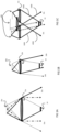
- Fig. 2A illustrates schematically a first embodiment of a projector assembly 5a have a LOE 28a and an image projector arrangement 20a.
- the image is shown as dashed lines representing lights rays.
- Image projector arrangement 20a generates and projects a partial image, and couples the partial image into waveguide 28a.
- the image projector arrangement includes a light source, spatial light modulator (such as a liquid crystal on silicon, or "LCOS”) and collimating optics. These components may advantageously be arranged on surfaces of a number of beam splitter prisms, for example, polarized beam splitter (PBS) cubes, as is known in the art.
- PBS polarized beam splitter
- Image projector arrangement 20a is deployed to introduce the partial image into the waveguide so as to propagate the partial image within the waveguide by internal reflection from the pair of parallel external surfaces.
- the introduction of the partial image into the waveguide is achieved via a suitable optical arrangement, referred to as a coupling-in arrangement, which typically includes a prism with suitably angled surfaces associated with a side edge of the LOE or one of the major surfaces of the LOE and/or one or more coupling-in reflectors which may be located within the LOE or associated with one of the surfaces thereof.
- a coupling-out arrangement 7a (shown as dashed rectangles on the LOE) associated with LOE 28a is deployed to couple-out the partial image from the waveguide towards the eye of the viewer.
- the projector arrangement 20a can be a wide optical arrangement, or may include a distinct optical arrangement for lateral aperture expansion.
- the coupling-out arrangement 7 is typically implemented as one or more sets of obliquely-angled, mutually-parallel internal partially reflecting surfaces, or as a diffractive optical element, all as is known in the art.
- the general region of the LOE from which the image illumination is coupled-out towards the eye of the viewer is designated by dashed lines.
- Fig. 2B illustrates schematically a second embodiment of a projector assembly 5b have a LOE 28b and two image projector arrangements 20b1 and 20b2.
- the two image projector arrangements 20b1 and 20b2 generate and project distinct partial images (shown as dashed lines representing lights rays).
- the partial images are coupled-in to waveguide 28b, such that each partial image is coupled-out (via respective coupling-out arrangements 7b1 and 7b2) towards the viewer.
- the partial images are coupled-in to waveguide at different angles relative to the waveguide so that coupled-out images do not overlap. It is apparent from Fig. 2B that there is a gap between the apertures of the image projector arrangements, leading to a corresponding gap in the coupled-out partial images.
- Fig. 2C illustrates schematically an embodiment of a display 70 according to the present invention.
- the display 70 is implemented via a combination of projector assembly 5a ( Figs. 2A ) and projector assembly 5b ( Fig. 2B ), although in principle there can be more than two projector assemblies.
- Projector assembly 5a includes image projector arrangement 20a and LOE 28a.
- Image projector arrangement 20a is configured to generate and project a first partial image corresponding to a first part of the image.
- Image projector arrangement 20a is deployed to introduce the first partial image into LOE 28a so as to propagate the first partial image within the LOE by internal reflection from the LOE's pair of parallel external surfaces.
- a coupling-out arrangement 7a (shown as dashed rectangles on the LOE) associated with LOE 28a is deployed to couple-out the first partial image from the waveguide towards the eye of the viewer.
- Projector assembly 5b includes image projector arrangements 20b1 and 20b2, and LOE 28b.
- Image projector arrangement 20b1 is configured to generate and project a second partial image corresponding to a second part of the image.
- Image projector arrangement 20b2 is configured to generate and project a third partial image corresponding to a third part of the image.
- Image projector arrangements 20b1 and 20b2 are deployed to introduce the second and third partial images, respectively, into LOE 28b2 so as to propagate the partial images within the LOE by internal reflection from the LOE's pair of parallel external surfaces.
- Coupling-out arrangements 7b1, 7b2 (shown as dashed rectangles on the LOE) associated with LOE 28b are deployed to couple-out the second and third partial images, respectively, from the waveguide towards the eye of the viewer.
- coupling-out arrangement 7a is in practice associated with projector assembly 5a, but shown in Fig. 2C here on projector assembly 5b in order to illustrate the overlapping effect of the coupled-out partial images.
- the first partial image (projected by image projector arrangement 20a) partially overlaps the second partial image (projected by image projector arrangement 20b1) and the third partial image (projected by image projector arrangement 20b2).
- LOEs 28a and 28b are deployed in overlapping relation with respect to one another such that projector assemblies 5a and 5b cooperate to display the image to an eye of the viewer.
- LOE 28a is shown as being located behind LOE 28b, in principle LOE 28a could alternatively be in front of LOE 28b.
- LOEs 28a and 28b should be as close to one another as possible, though an air gap, or a layer simulating an air gap, is typically required in order to maintain the light guiding properties of the LOE.
- the image projector arrangement is wider than its associated waveguide such that part of the image projector will extend over the side of the LOE, it is preferable to have image projector arrangements 20b1 and 20b2 extend over opposing sides of the LOE.
- the field and aperture continuity as well as pixel intensity uniformity should be maintained when the viewer's pupil is at different positions in the eye-box.
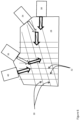
- Figs. 2D and 2E illustrate schematically a cross-sectional top-down view of projector assemblies 5a and 5b, showing partially overlapping partial images coupled out towards eye-box 14.
- Fig. 2D shows ray directions corresponding to two pixels in the left half of the overall field of view, which are generated by projector arrangements 20a and 20b1, and coupled-out by coupling-out arrangements 7a and 7b1, respectively.
- Fig. 2E shows ray directions corresponding to two pixels in the right half of the overall field of view, which are generated by projector arrangements 20a and 20b2, and coupled-out by coupling-out arrangements 7a and 7b2, respectively.
- Figs. 2F and 2G correspond to Figs. 2D and 2E and illustrate schematically selected points (pixels) in the projected fields in angular space as would be observed by a pupil at each of pupil position 15a (shown in Fig. 2F ) and pupil position 15b (shown in Fig. 2G).
- Figs. 2F and 2G demonstrate the variance in the perceived image according to the viewer's pupil position.
- overlap region region(s) of overlap
- region of partial overlap will now be used to refer to image data that is simultaneously projected by more than one image project arrangement.
- typically a subset of the pixels within the region of overlap will illuminate the pupil from both projectors at any given time (the other pixels reaching the eye from only one projector while light from the other falls to the left or right of the pupil).
- pixels 1000F, 1002F, 2002F and 2000F are produced by light rays 1000, 1002a/b, 2002a/b and 2000, respectively (shown in Figs. 2D-2E ).
- similarly numbered pixels correspond to identical image information, as shown by their being positioned, in both Figs. 2F and 2G , at identical locations within the field of the image.
- pixel 1002F is simultaneously coupled-out towards the viewer by light ray 1002a and light ray 1002b from (originating from image projector arrangements 20a and 20b1, respectively). Both of these light rays illuminate the pupil.
- pixel 2002F is also simultaneously coupled-out towards the viewer by two light rays, being light rays 2002a and 2002b (originating from image projectors 20a and 20b2, respectively). However, in this case, only light ray 2002b illuminates the pupil.
- the "selected pixels" within the region of overlap preferably include pixel 1002F but not 2002F.
- the selected pixels within the region of overlap preferably include pixel 2002F but not 1002F.
- the pixel intensity of selected pixels in regions of overlap are reduced (e.g. via a controller, as will be further detailed below) so as to enhance the perceived uniformity of the image when viewed by a viewer.
- Figs. 3A and 3D illustrate examples of angular power intensity distribution (lateral axis only) of the partial images generated by the separate image projector arrangements 20b1, 20a and 20b2 (respectively denoted '(a)', '(b)', and '(c)') after a reduction in the intensity of pixels in part of the overlapping regions of the partial images.
- Figs. 3B, 3C and 3E illustrate examples of the lateral angular distribution of pixel intensities when the partial images are combined. It should be noted that Figs. 3A-3E illustrate theoretical pixel intensity distribution across the field, while in practice the intensity distribution of a given projector arrangement is typically non-uniform across the projected field, and gradually drops off towards the ends of the field.
- Fig. 3A is optimized for the viewer's pupil being located at pupil position 15a (see Figs. 2D-2H), in which case the subset of the pixels in image area 50 that reach the central pupil position from two projectors are reduced to half the intensity, so that after combining the images from all image projector arrangements the pixel intensity reaching the eye will be uniform across the entire image, as shown by the dashed line in Fig. 3B.
- the controller may vary the subset of pixels for which the intensity is reduced based on an overlap region adjustment input, e.g. based on the viewer's anticipated or known pupil position.
- the overlap region adjustment input may be derived automatically, e.g. via a pupil sensor.
- the overlap region adjustment input may be derived by manual input from the user. For example, a test image can be displayed to the user with overlapping parts. The user can be asked to look at various parts of the image and provide input to reduce the intensity of select pixels, such as by actuating a knob or lever coupled to the controller, when the image appears uniform.
- the user can provide feedback to adjustments made by the controller, for example during a calibration process. The controller receiving such feedback can vary the subset of pixels for intensity reduction until a best approximation for a uniform perceived image is achieved.
- Fig. 3D illustrates the angular power intensity distribution based on the viewer's eye located at pupil position 15b, after having reduced the intensity of the pixels corresponding to image area 50'.
- the image area 50' for pixel intensity reduction in Fig. 3D are somewhat different than the image area 30 in Fig. 3A due to the different pupil position.
- the intensity across the combined image is made uniform, as shown in Fig. 3E.
- pupil position changes when the viewer looks in different directions, i.e., at different parts of the projected image due to rotation of the eye about its center of rotation.
- the sensitivity of the human eye to variations in image intensity is much greater in the central region of view, while a person is much more tolerant of intensity variations in their peripheral vision. Accordingly, it is typically sufficient to perform an adjustment to optimize the region of intensity correction for each "seam" (region of overlap) for the pupil position which corresponds to an eye direction looking towards that seam.
- the aforementioned manual user adjustment may advantageously be performed as part of a software-guided calibration process in which the user is first instructed to look at a projected calibration image spanning a first seam, e.g., to the left, and to make the manual adjustment until that calibration image appears uniform, and then to look at a projected calibration image spanning a second seam, e.g., to the right, and to make the manual adjustment until that calibration image appears uniform.
- Those settings may then be used continuously for subsequent projection of images, independent of the instantaneous pupil position, with the understanding that the seam regions of the field of view will be at high quality while the user is looking at them with her central vision, and may be somewhat non-uniform in the peripheral vision.
- a pupil sensor can be deployed to dynamically detect eyeball rotation (e.g. as a function of deviation from a predetermined rotation center). Based on the detected eyeball rotation, the controller can determine the subset of pixels to be intensity reduced and make appropriate adjustments, providing full-field uniformity optimization for each instantaneous position of the pupil.
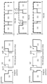
- Figs. 4A - 4C illustrate schematically cross-sectional views of different configurations of a display according to the present invention.
- the display can include a separate waveguide for each image projector arrangement.
- the display includes three projector arrangements, and three corresponding waveguides, as shown in Fig. 4A .
- the three projector arrangement configuration advantageously allows the middle field, corresponding to the viewer looking at the center of the image (as opposed to looking to the sides) to be generated by the middle projector arrangement only and generally free of overlap and naturally uniform. Parenthetically, both here and in all other implementations described herein, the fields of view of the different projector arrangements do not need to be equal.
- Fig. 4B illustrates schematically an alternative embodiment where two projector arrangements are used with corresponding waveguides.
- This configuration advantageously is relatively simpler to manufacture (as well as operate) due to the reduced number of components.
- Use of differing sized FOV for the two projectors may allow offsetting of the seam region outside the central region.
- Fig. 4C illustrates schematically an embodiment having non-parallel waveguides 41a, 41b and 41c, which can further expand the image field by orienting the waveguides to extend around or partially encompass the observer (or an eye of the observer).
- the edges of the waveguides may be within the field of view of the observer, and might therefore cause a scattering and/or perturbation effect in the viewed image.
- These effects can be at least partially suppressed or eliminated by introducing an index-matched medium 43 (e.g. such as conformal plastic) between these edges thereby forming an optically smooth transition with the edges of the LOE.
- an index-matched medium 43 e.g. such as conformal plastic
- This embodiment can be further extended to multiple light guide panels encompassing any desired angle around the observer, and optionally replicated in two dimensions to provide an overall concave display, which could be extended to form a viewing dome or the like.
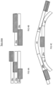
- Fig. 5A illustrates schematically an embodiment of a display configured for 2D image expansion.
- the display has two projector arrangements 24 and 26 deployed to couple-in partial images to a single 2D LOE 28 for 2D image expansion.
- LOE 28 has two non-parallel sets 30, 32 of mutually parallel facets or diffractive elements.
- LOEs configured for 2D image expansion are further described in WO 2019/016813 (see, e.g., Figs. 5A , 6 of that publication).
- Projector arrangements 24, 26 project images at two different angles into LOE 28.
- the light from both projector arrangements is first reflected by facets 30 (thereby expanding aperture in one dimension, e.g. vertically) and subsequently reflected by facets 32 outward toward the observer while simultaneously expanding the aperture in the other dimension, e.g. horizontally.
- Each projector arrangement generates a partial image, which is then coupled-out to the viewer such that the viewer sees a combined image.
- the region of overlap between the partial images may be a side-by-side horizontal arrangement as shown in Fig. 5B or a top-bottom vertical arrangement as shown in Fig. 5C .
- the angle of horizontal or vertical tilt between the projector arrangements 24 and 26 determines the offset between the optical axes of the two projectors, and hence the degree of vertical and horizontal overlap exists in the image viewed by the observer.
- the actual positioning of the projector arrangements 24 and 26 is typically not critical because two-dimensional aperture expansion is performed by facets 32 and 30 on light from both projector arrangements.
- the intensities projected by the two projector arrangements must be managed in order to maintain uniform intensity. In this case, variations of intensity across the eye-box will be reduced relative to the multiple waveguide configuration.
- Fig. 6 illustrates schematically a second embodiment of a display configured for 2D image expansion.
- This embodiment uses four projector arrangements.
- Projector 34 couples-in to LOE 28 partial images for reflection and aperture expansion by facets 30 and then reflection only by facets 32.
- projector arrangement 36 couples-in to LOE 28 partial images for reflection and aperture expansion by facets 32 and then reflection only by facets 30.
- Projector arrangement 38 is oriented to reflect primarily from facets 32 while projector arrangement 40 is oriented for reflection primarily from facets 30. Light from both projector arrangements 38 and 40 experience some back-and-forth reflection between the perpendicular sets of facets 30, 32 causing aperture expansion in both the vertical and horizontal dimensions.
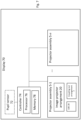
- FIG. 7 illustrates schematically an example functional block diagram of a display in accordance with certain embodiments.
- Display 70 includes controller 74, and two or more projector assemblies 5-1 - 5- n .
- Each projector assembly 5 includes at least one image projector arrangement 20, and at least one LOE 28 having a pair of parallel external surfaces.
- Image projector arrangement 20 is configured to generate and project a partial image and is deployed so as introduce the partial image to LOE 28.
- LOE 28 is configured to propagate the partial image within the LOE by internal reflection from the pair of parallel external surfaces.
- each projector assembly includes a coupling-out arrangement 7 associated with LOE 28 and configured for coupling-out the partial image from the LOE towards the eye of the viewer.
- the LOEs 28 of respective projector assemblies are deployed in overlapping relation with one another such that each projector assembly projects a respective partial image corresponding to a respective part of the image to be displayed to the viewer.
- the respective parts of the image have partial overlap so that the two or more projector assemblies cooperate to display the image to the viewer.
- Controller 74 is associated with the image projector arrangements of each projector assembly. Controller 74 includes at least one processor 76 associated with a memory 78. Processor 76, in combination with associated memory 78, is configured to execute one or more functional modules stored in memory 78 for controlling display 70, including, e.g. reducing a pixel intensity of selected pixels projected by at least one image projector arrangement, the selected pixels being in a region of partial overlap between parts of the image, so as to enhance the perceived uniformity of the image displayed to the viewer.
- the controller may be configured to vary the pixel intensities of selected pixels in the region of overlap taking into account any variance in the projector arrangements' pixel intensities projected across the field and the viewer's pupil position within the eye-box.
- the controller may be configured to gradually reduce the intensity of the selected pixels projected by one projector arrangement across the region of partial overlap, and to gradually increase the intensity of the selected pixels projected by the second projector arrangement across the region of partial overlap.
- controller 74 may be coupled to a user input device (not shown) configured for providing user input to controller 74, for example as described above with reference to Figs. 3A and 3D.
- the controller may be physically located within the same housing or different housing than other components of display 70.
- different components of the controller may be physically located apart from one another.
- the controller is preferably implemented in, but not limited to, a head-mounted display, and most preferably in an eye-glasses form factor.
- display 70 further includes a pupil sensor 72 configured to detect a current pupil position of the viewer, and to update the controller 74 with data indicative of current pupil position.
- controller 74 is configured to determine a subset of common pixels between the partial images, based on the data obtained from the pupil sensor or based on a user input, for which image illumination is arriving at the pupil from two projectors simultaneously, and to implement intensity reduction for that subset of pixels. In some embodiments, the controller is further configured to vary the selection of the subset of common pixels in response to an overlap region adjustment input.
- the overlap region adjustment input can be derived from the pupil sensor, or from manual user input.
- the controller can be configured to obtain calibration data in cooperation with pupil sensor 72 and store the obtained calibration data in memory 78, and determine the appropriate overlap region adjustment for every pupil position based on the stored calibration data.
- Fig. 8 illustrates an example flow-chart of a method for displaying an image to an eye of a viewer in accordance with certain embodiments where a sensor is used to detect pupil position of the viewer, either as a one-time calibration process or for ongoing real time adjustment. All steps are performed by processor 76 unless otherwise noted.
- the pupil sensor detects the pupil position of the viewer's eye.
- step 88 at each different pupil position, determine a subset of pixels in the overlapping region of the image displayed to the viewer.
- the intensity of pixels within the determined subset is reduced so as to enhance the uniformity of the image displayed to the eye of the viewer.
- This intensity reduction is typically performed by modifying the image data sent to the projector, reducing the pixel intensity values for the relevant subset of pixels which are sent to both projectors. For example, a pixel with RGB values of (200,80,168) from the region of perceived overlap could be sent to both projectors as if the pixel data were a dimmer pixel of the same color, such as (100,40,84), assuming ideal linear response of the projector.
- the correction may need to be calibrated according to the specific hardware properties of the projector assemblies. Additionally, as described above, the output intensity of the different projector assemblies are typically not uniform across the field, and intensity correction should preferably take into account these non-uniformities.
- intensity reduction profile has been illustrated herein as a step function, with 50% intensity being contributed by each projector in the region of perceived overlap, it should be noted that the subdivision of intensity between the two projectors need not be equal for any given pixel, and that the smoothness of the resulting image will typically be greatly enhanced by use of a linear tapering, or an otherwise smoothed transition profile.
- Fig. 9A illustrates an embodiment where the visible image intensity progressively hands-off between each two adjacent projectors across the region of perceived overlap, preferably starting at more than 80% intensity at the beginning of the region of perceived overlap, passing 50:50 somewhere in the middle, and reaching less than 20% contribution to the relevant pixel intensity at the outer extremity of the perceived-overlapping pixels for each projector.
- This progressive variation is preferably monotonic and occurs gradually across the transition area.
- Fig. 9B illustrates the intensity distribution in the combined mage after the correction by linear tapering as described in Fig. 9A.
- the corrected image may be well within acceptable limits for viewing at any pupil position, thereby obviating the need to detect pupil positon and perform dynamic correction, as illustrated in Fig. 9C.
- the intensity reduction profile may advantageously be temporarily switched to the step function profile during calibration in order to render the intensity non-uniformity more noticeable, and then switch back to a progressive variation during normal operation.
- the progressive intensity degradation described here can be modified according to the attenuation characteristics of the respective projector arrangements, as well as the pupil position within the eye-box, in order to maintain a uniform image intensity as viewed by an eye.
- the displays provided herein may be implemented both in virtual reality and in augmented reality applications (i.e. where virtual display elements are combined with a direct view of the real world).
Landscapes
- Physics & Mathematics (AREA)
- General Physics & Mathematics (AREA)
- Optics & Photonics (AREA)
- Nonlinear Science (AREA)
- Testing, Inspecting, Measuring Of Stereoscopic Televisions And Televisions (AREA)
- Projection Apparatus (AREA)
- Controls And Circuits For Display Device (AREA)
- Transforming Electric Information Into Light Information (AREA)
Applications Claiming Priority (3)
| Application Number | Priority Date | Filing Date | Title |
|---|---|---|---|
| US201862672635P | 2018-05-17 | 2018-05-17 | |
| US201862750269P | 2018-10-25 | 2018-10-25 | |
| PCT/IB2019/054062 WO2019220386A1 (en) | 2018-05-17 | 2019-05-16 | Near-eye display having overlapping projector assemblies |
Publications (3)
| Publication Number | Publication Date |
|---|---|
| EP3794397A1 EP3794397A1 (en) | 2021-03-24 |
| EP3794397A4 EP3794397A4 (en) | 2021-07-07 |
| EP3794397B1 true EP3794397B1 (en) | 2025-01-01 |
Family
ID=68540908
Family Applications (1)
| Application Number | Title | Priority Date | Filing Date |
|---|---|---|---|
| EP19804151.9A Active EP3794397B1 (en) | 2018-05-17 | 2019-05-16 | Near-eye display having overlapping projector assemblies |
Country Status (8)
| Country | Link |
|---|---|
| US (4) | US11442273B2 (he) |
| EP (1) | EP3794397B1 (he) |
| JP (2) | JP7446620B2 (he) |
| KR (1) | KR102750567B1 (he) |
| CN (1) | CN112119344B (he) |
| IL (1) | IL278511B2 (he) |
| TW (1) | TW201947281A (he) |
| WO (1) | WO2019220386A1 (he) |
Families Citing this family (49)
| Publication number | Priority date | Publication date | Assignee | Title |
|---|---|---|---|---|
| US10048499B2 (en) | 2005-11-08 | 2018-08-14 | Lumus Ltd. | Polarizing optical system |
| IL232197B (he) | 2014-04-23 | 2018-04-30 | Lumus Ltd | מערכת תצוגת ראש קומפקטית |
| IL237337B (he) | 2015-02-19 | 2020-03-31 | Amitai Yaakov | מערכת תצוגת ראש קומפקטית בעלת תמונה אחידה |
| US11500143B2 (en) | 2017-01-28 | 2022-11-15 | Lumus Ltd. | Augmented reality imaging system |
| US12205231B2 (en) | 2017-07-03 | 2025-01-21 | Holovisions | Holovisions™—adjustable and/or modular augmented reality (AR) eyewear with a movable transflective mirror and different viewing modes |
| US12436394B2 (en) | 2017-07-03 | 2025-10-07 | Holovisions | Augmented reality (or mixed reality) eyewear with see-through optical elements having individually-adjustable opacity/reflectivity levels |
| US12013538B2 (en) | 2017-07-03 | 2024-06-18 | Holovisions LLC | Augmented reality (AR) eyewear with a section of a fresnel reflector comprising individually-adjustable transmissive-reflective optical elements |
| EP3688526B1 (en) | 2017-09-29 | 2023-07-12 | Lumus Ltd. | Augmented reality display |
| US11656472B2 (en) | 2017-10-22 | 2023-05-23 | Lumus Ltd. | Head-mounted augmented reality device employing an optical bench |
| CN111417883B (zh) | 2017-12-03 | 2022-06-17 | 鲁姆斯有限公司 | 光学设备对准方法 |
| IL275615B (he) | 2018-01-02 | 2022-08-01 | Lumus Ltd | מייצגים של מציאות מוגברת עם יישור אקטיבי ושיטות תואמות |
| US10551544B2 (en) | 2018-01-21 | 2020-02-04 | Lumus Ltd. | Light-guide optical element with multiple-axis internal aperture expansion |
| JP7389491B2 (ja) | 2018-04-08 | 2023-11-30 | ルムス エルティーディー. | 光学サンプルの特性評価 |
| EP4339656A3 (en) | 2018-05-14 | 2024-06-05 | Lumus Ltd. | Projector configuration with subdivided optical aperture for near-eye displays, and corresponding optical systems |
| IL278511B2 (he) | 2018-05-17 | 2025-01-01 | Lumus Ltd | תצוגה קרובה לעין המכילה מכלולי מקרן חופפים |
| IL259518B2 (he) | 2018-05-22 | 2023-04-01 | Lumus Ltd | מערכת אופטית ושיטה לשיפור אחידות שדה אור |
| JP7417234B2 (ja) | 2018-05-23 | 2024-01-18 | ルムス エルティーディー. | 部分的に反射する内部表面を備えた導光光学素子を含む光学システム |
| WO2019244093A1 (en) | 2018-06-21 | 2019-12-26 | Lumus Ltd. | Measurement technique for refractive index inhomogeneity between plates of a lightguide optical element (loe) |
| CN112424670B (zh) | 2018-07-16 | 2023-01-17 | 鲁姆斯有限公司 | 采用偏振内反射器的光导光学元件 |
| KR102781637B1 (ko) | 2018-08-26 | 2025-03-13 | 루머스 리미티드 | 근안 디스플레이에서의 반사 억제 |
| TWI865343B (zh) | 2018-09-09 | 2024-12-01 | 以色列商魯姆斯有限公司 | 包括具有二維擴展的光導光學元件的光學系統 |
| TWM642752U (zh) | 2018-11-08 | 2023-06-21 | 以色列商魯姆斯有限公司 | 用於將圖像顯示到觀察者的眼睛中的顯示器 |
| US11947130B2 (en) | 2018-11-08 | 2024-04-02 | Lumus Ltd. | Optical devices and systems with dichroic beamsplitter color combiner |
| JP3226277U (ja) | 2018-11-11 | 2020-05-14 | ルムス エルティーディー. | 中間ウィンドウを有するニアアイディスプレイ |
| EP3903138B1 (en) | 2019-01-24 | 2023-03-08 | Lumus Ltd. | Optical systems including loe with three stage expansion |
| WO2020174433A1 (en) | 2019-02-28 | 2020-09-03 | Lumus Ltd. | Compact collimated image projector |
| TWI800657B (zh) | 2019-03-12 | 2023-05-01 | 以色列商魯姆斯有限公司 | 圖像投影儀 |
| TWI880746B (zh) | 2019-05-06 | 2025-04-11 | 以色列商魯姆斯有限公司 | 用於觀看場景的透明光導和近眼顯示器 |
| BR112021022229A2 (pt) | 2019-06-27 | 2022-02-22 | Lumus Ltd | Aparelho |
| CN117943933B (zh) | 2019-11-25 | 2025-12-02 | 鲁姆斯有限公司 | 可调节安装装置以及包括其的装置 |
| IL270991B (he) | 2019-11-27 | 2020-07-30 | Lumus Ltd | מדריך אור עם אלמנט אופטי לביצוע ערבול קיטובי |
| CA3223538C (en) | 2019-12-05 | 2024-02-20 | Lumus Ltd | Light-guide optical element employing complementary coated partial reflectors, and light-guide optical element having reduced light scattering |
| JP7497079B2 (ja) | 2019-12-08 | 2024-06-10 | ルーマス リミテッド | コンパクト画像プロジェクタを備える光学系 |
| US12019249B2 (en) | 2019-12-25 | 2024-06-25 | Lumus Ltd. | Optical systems and methods for eye tracking based on redirecting light from eye using an optical arrangement associated with a light-guide optical element |
| AU2020418462B2 (en) * | 2019-12-30 | 2026-02-12 | Lumus Ltd. | Optical systems including light-guide optical elements with two-dimensional expansion |
| IL294538B2 (he) | 2020-02-24 | 2025-12-01 | Lumus Ltd | משלב מציאות מעורבת |
| US20210263317A1 (en) * | 2020-02-25 | 2021-08-26 | Facebook Technologies, Llc | Angularly selective diffusive combiner |
| KR200498906Y1 (ko) | 2020-05-12 | 2025-03-10 | 루머스 리미티드 | 회전가능한 광도파관 |
| EP4158397A4 (en) | 2020-06-01 | 2024-01-31 | Lumus Ltd. | Virtual image delivery system for near eye displays |
| JP7475231B2 (ja) * | 2020-07-20 | 2024-04-26 | 京セラ株式会社 | 3次元表示装置 |
| KR102281834B1 (ko) | 2020-07-24 | 2021-07-26 | 주식회사 레티널 | 증강 현실용 화상의 영상 보정 장치 |
| KR20230054841A (ko) | 2020-08-23 | 2023-04-25 | 루머스 리미티드 | 도파관으로부터의 글린트 및 고스트를 감소시키는 이미지의 2차원 확장을 위한 광학 시스템 |
| DE202021104723U1 (de) | 2020-09-11 | 2021-10-18 | Lumus Ltd. | An ein optisches Lichtleiterelement gekoppelter Bildprojektor |
| CN116368413A (zh) | 2020-10-01 | 2023-06-30 | 鲁姆斯有限公司 | 复合光导光学元件 |
| WO2022130372A1 (en) | 2020-12-17 | 2022-06-23 | Lumus Ltd. | Optical systems and methods for eye tracking based on eye imaging via collimating element and light-guide optical element |
| EP4237903B1 (en) * | 2021-03-01 | 2024-09-04 | Lumus Ltd. | Optical system with compact coupling from a projector into a waveguide |
| JP7475757B2 (ja) | 2021-07-04 | 2024-04-30 | ルーマス リミテッド | 積層導光素子が視野の異なる部分を提供するディスプレイ |
| AU2024248072A1 (en) * | 2023-03-31 | 2025-05-29 | Lumus Ltd. | Optical waveguide with split aperture |
| WO2025007092A1 (en) * | 2023-06-30 | 2025-01-02 | Vuzix Corporation | Image light guide projector system alignment |
Family Cites Families (109)
| Publication number | Priority date | Publication date | Assignee | Title |
|---|---|---|---|---|
| US2329001A (en) | 1941-11-25 | 1943-09-07 | Randolph B Delmore | Pilot operated valve |
| FR1485692A (fr) | 1966-05-11 | 1967-06-23 | Vanne perfectionnée | |
| US3544190A (en) | 1968-11-29 | 1970-12-01 | Xerox Corp | Lens strip optical scanning system |
| FR2617562B1 (fr) | 1987-07-01 | 1989-11-10 | Verdelet Alain | Ensemble de vanne a clapet |
| US5770847A (en) | 1994-12-23 | 1998-06-23 | Spectra-Physics Scanning Systems, Inc. | Bar code reader with multi-focus lens |
| US5999836A (en) | 1995-06-06 | 1999-12-07 | Nelson; Robert S. | Enhanced high resolution breast imaging device and method utilizing non-ionizing radiation of narrow spectral bandwidth |
| IL148804A (en) | 2002-03-21 | 2007-02-11 | Yaacov Amitai | Optical device |
| US6752169B2 (en) | 2002-10-31 | 2004-06-22 | Lindsay Manufacturing Co. | Pressure regulator and shut-off valve |
| US7495638B2 (en) | 2003-05-13 | 2009-02-24 | Research Triangle Institute | Visual display with increased field of view |
| US7298940B2 (en) | 2003-06-10 | 2007-11-20 | Abu-Ageel Nayef M | Illumination system and display system employing same |
| US7475992B2 (en) | 2003-06-10 | 2009-01-13 | Abu-Ageel Nayef M | Light recycler and color display system including same |
| US7400447B2 (en) | 2003-09-03 | 2008-07-15 | Canon Kabushiki Kaisha | Stereoscopic image display device |
| IL157838A (he) | 2003-09-10 | 2013-05-30 | Yaakov Amitai | התקן אופטי בעל בהירות גבוהה |
| IL157837A (en) | 2003-09-10 | 2012-12-31 | Yaakov Amitai | Substrate-guided optical device particularly for three-dimensional displays |
| IL162573A (he) | 2004-06-17 | 2013-05-30 | Lumus Ltd | רכיב אופטי במצע מוליך בעל מפתח גדול |
| US20070202285A1 (en) | 2004-12-15 | 2007-08-30 | Fina Technology, Inc. | Articles having improved clarity, prepared from propylene-ethylene copolymers |
| US7413328B2 (en) | 2004-12-30 | 2008-08-19 | Honeywell International Inc. | Remotely coupled hybrid HUD backlight |
| US10073264B2 (en) | 2007-08-03 | 2018-09-11 | Lumus Ltd. | Substrate-guide optical device |
| IL166799A (he) | 2005-02-10 | 2014-09-30 | Lumus Ltd | משטחים מפצלי אלומה לשימוש בתוך מצע מוליך |
| US7724443B2 (en) | 2005-02-10 | 2010-05-25 | Lumus Ltd. | Substrate-guided optical device utilizing thin transparent layer |
| WO2006085310A1 (en) | 2005-02-10 | 2006-08-17 | Lumus Ltd. | Substrate-guided optical device particularly for vision enhanced optical systems |
| EP1848966A1 (en) | 2005-02-17 | 2007-10-31 | Lumus Ltd | Personal navigation system |
| US7434940B2 (en) * | 2005-09-06 | 2008-10-14 | Hewlett-Packard Development Company, L.P. | Light coupling system and method |
| IL171820A (he) | 2005-11-08 | 2014-04-30 | Lumus Ltd | רכיב אופטי מקטב לצימוד אור בתוך מצע מוליך |
| US10048499B2 (en) | 2005-11-08 | 2018-08-14 | Lumus Ltd. | Polarizing optical system |
| IL173715A0 (en) | 2006-02-14 | 2007-03-08 | Lumus Ltd | Substrate-guided imaging lens |
| IL174170A (he) | 2006-03-08 | 2015-02-26 | Abraham Aharoni | התקן ושיטה לכיוונון דו–עיני |
| IL177618A (he) | 2006-08-22 | 2015-02-26 | Lumus Ltd | רכיב אופטי במצע מוליך |
| EP2142953B1 (en) | 2007-04-22 | 2019-06-05 | Lumus Ltd | A collimating optical device and system |
| IL183637A (he) | 2007-06-04 | 2013-06-27 | Zvi Lapidot | מערכת תצוגת ראש |
| JP5031452B2 (ja) * | 2007-06-20 | 2012-09-19 | キヤノン株式会社 | 画像観察装置及び画像観察システム |
| JPWO2009157352A1 (ja) * | 2008-06-23 | 2011-12-08 | ソニー株式会社 | 面光源装置および表示装置 |
| US7949252B1 (en) | 2008-12-11 | 2011-05-24 | Adobe Systems Incorporated | Plenoptic camera with large depth of field |
| WO2010067114A1 (en) | 2008-12-12 | 2010-06-17 | Bae Systems Plc | Improvements in or relating to waveguides |
| JP2010266787A (ja) * | 2009-05-18 | 2010-11-25 | Canon Inc | 画像表示装置 |
| JP5104823B2 (ja) * | 2009-07-29 | 2012-12-19 | 株式会社島津製作所 | 表示装置 |
| US8730183B2 (en) * | 2009-09-03 | 2014-05-20 | Obscura Digital | Large scale multi-user, multi-touch system |
| US9110495B2 (en) * | 2010-02-03 | 2015-08-18 | Microsoft Technology Licensing, Llc | Combined surface user interface |
| EP2564259B1 (en) * | 2010-04-30 | 2015-01-21 | Beijing Institute Of Technology | Wide angle and high resolution tiled head-mounted display device |
| US8649099B2 (en) | 2010-09-13 | 2014-02-11 | Vuzix Corporation | Prismatic multiple waveguide for near-eye display |
| CN103384854B (zh) | 2010-12-22 | 2017-03-15 | 视瑞尔技术公司 | 用于跟踪使用者的组合光调制装置 |
| JP6119091B2 (ja) | 2011-09-30 | 2017-04-26 | セイコーエプソン株式会社 | 虚像表示装置 |
| JP5879886B2 (ja) * | 2011-10-03 | 2016-03-08 | セイコーエプソン株式会社 | 虚像表示装置及びその製造方法 |
| DE102012205164B4 (de) | 2012-03-29 | 2021-09-09 | Fraunhofer-Gesellschaft zur Förderung der angewandten Forschung e.V. | Projektionsdisplay und Verfahren zur Projektion virtueller Bilder |
| WO2013163347A1 (en) | 2012-04-25 | 2013-10-31 | Rockwell Collins, Inc. | Holographic wide angle display |
| IL219907A (he) | 2012-05-21 | 2017-08-31 | Lumus Ltd | מערכת תצוגת ראש משולבת עם עקיבת עיין |
| US20150205034A1 (en) * | 2012-08-13 | 2015-07-23 | Bayer Materialscience Ag | Light guide plate comprising decoupling elements |
| WO2014074202A2 (en) | 2012-08-20 | 2014-05-15 | The Regents Of The University Of California | Monocentric lens designs and associated imaging systems having wide field of view and high resolution |
| US9933684B2 (en) | 2012-11-16 | 2018-04-03 | Rockwell Collins, Inc. | Transparent waveguide display providing upper and lower fields of view having a specific light output aperture configuration |
| US9690107B2 (en) * | 2013-03-15 | 2017-06-27 | Trumpf Laser Gmbh | Device for wavelength combining of laser beams |
| US20160363769A1 (en) * | 2013-11-25 | 2016-12-15 | Sharp Kabushiki Kaisha | Light guide and head mounted display |
| CN107219628B (zh) * | 2013-11-27 | 2020-05-01 | 奇跃公司 | 虚拟和增强现实系统与方法 |
| EP2886834A1 (en) | 2013-12-20 | 2015-06-24 | IMI Hydronic Engineering International SA | A valve and a method of controlling a valve in a fluid conduit |
| IL232197B (he) | 2014-04-23 | 2018-04-30 | Lumus Ltd | מערכת תצוגת ראש קומפקטית |
| CN105445935B (zh) * | 2014-06-26 | 2017-12-29 | 联想(北京)有限公司 | 显示装置和电子设备 |
| JP6575117B2 (ja) | 2015-04-06 | 2019-09-18 | セイコーエプソン株式会社 | 表示装置、表示装置の制御方法、および、プログラム |
| IL235642B (he) | 2014-11-11 | 2021-08-31 | Lumus Ltd | מערכת תצוגת ראש קומפקטית מוגנת על ידי אלמנט עם מבנה על–דק |
| IL236491B (he) | 2014-12-25 | 2020-11-30 | Lumus Ltd | שיטה לייצור רכיב אופטי במצע מוליך |
| IL236490B (he) | 2014-12-25 | 2021-10-31 | Lumus Ltd | רכיב אופטי במצע מוליך |
| US10436951B2 (en) * | 2015-01-21 | 2019-10-08 | Tesseland, Llc | Display device with total internal reflection |
| IL237337B (he) | 2015-02-19 | 2020-03-31 | Amitai Yaakov | מערכת תצוגת ראש קומפקטית בעלת תמונה אחידה |
| DE102015122055B4 (de) * | 2015-12-17 | 2018-08-30 | Carl Zeiss Ag | Optisches System sowie Verfahren zum Übertragen eines Quellbildes |
| JP6641974B2 (ja) * | 2015-12-18 | 2020-02-05 | セイコーエプソン株式会社 | 虚像表示装置 |
| JP6480020B2 (ja) * | 2016-01-22 | 2019-03-06 | シャープ株式会社 | 照明装置および電子機器 |
| TW201732373A (zh) | 2016-02-24 | 2017-09-16 | Omron Tateisi Electronics Co | 顯示裝置 |
| EP3458898B1 (en) | 2016-05-18 | 2023-02-15 | Lumus Ltd. | Head-mounted imaging device |
| US10353202B2 (en) * | 2016-06-09 | 2019-07-16 | Microsoft Technology Licensing, Llc | Wrapped waveguide with large field of view |
| EP4451042A3 (en) * | 2016-06-21 | 2025-03-26 | Apple Inc. | Optical systems for displays |
| JP2019520610A (ja) | 2016-06-21 | 2019-07-18 | 株式会社Nttドコモ | ウェアラブルディスプレイのための照明装置 |
| WO2018008577A1 (ja) * | 2016-07-06 | 2018-01-11 | パナソニックIpマネジメント株式会社 | 頭部装着型ディスプレイ装置 |
| JP2018054978A (ja) | 2016-09-30 | 2018-04-05 | セイコーエプソン株式会社 | 虚像表示装置及びその製造方法 |
| BR112018006747A2 (pt) | 2016-10-09 | 2018-10-16 | Lumus Ltd. | multiplicador de abertura usando um guia de ondas retangular |
| JP6829482B2 (ja) | 2016-11-08 | 2021-02-10 | ルムス エルティーディー. | 光学遮断端部を備えた光ガイド装置およびその製造方法 |
| KR20190000456U (ko) | 2016-12-02 | 2019-02-19 | 루머스 리미티드 | 소형 시준 이미지 프로젝터를 구비한 광학 시스템 |
| KR102296369B1 (ko) | 2016-12-31 | 2021-09-01 | 루머스 리미티드 | 도광 광학 소자를 통한 망막 이미징 기반 안구 추적기 |
| EP3566092B1 (en) | 2017-01-04 | 2022-10-05 | Lumus Ltd. | Optical system for near-eye displays |
| KR102481569B1 (ko) | 2017-02-22 | 2022-12-26 | 루머스 리미티드 | 광 가이드 광학 어셈블리 |
| CN109416433B (zh) | 2017-03-22 | 2021-06-01 | 鲁姆斯有限公司 | 交叠的反射面构造 |
| IL251645B (he) | 2017-04-06 | 2018-08-30 | Lumus Ltd | מוליך גלים ושיטה לייצור |
| KR102638818B1 (ko) | 2017-07-19 | 2024-02-20 | 루머스 리미티드 | Loe를 통한 lcos 조명 |
| EP3688526B1 (en) | 2017-09-29 | 2023-07-12 | Lumus Ltd. | Augmented reality display |
| US11656472B2 (en) | 2017-10-22 | 2023-05-23 | Lumus Ltd. | Head-mounted augmented reality device employing an optical bench |
| DE102017125731A1 (de) * | 2017-11-03 | 2019-05-09 | Carl Zeiss Ag | Lichtleiter, Abbildungsvorrichtung und HMD mit separaten Abbildungskanälen |
| DE102017126908A1 (de) * | 2017-11-15 | 2019-05-16 | Carl Zeiss Ag | Lichtleiter für ein HMD, HMD und Verfahren zum Übertragen eines Bildes in einem HMD |
| AU2018372665B2 (en) | 2017-11-21 | 2023-01-19 | Lumus Ltd. | Optical aperture expansion arrangement for near-eye displays |
| US20190170327A1 (en) | 2017-12-03 | 2019-06-06 | Lumus Ltd. | Optical illuminator device |
| CN111417883B (zh) | 2017-12-03 | 2022-06-17 | 鲁姆斯有限公司 | 光学设备对准方法 |
| WO2019106636A1 (en) | 2017-12-03 | 2019-06-06 | Lumus Ltd. | Optical device testing method and apparatus |
| KR20200097289A (ko) | 2017-12-10 | 2020-08-18 | 루머스 리미티드 | 이미지 프로젝터 |
| FI129586B (en) | 2017-12-22 | 2022-05-13 | Dispelix Oy | Waveguide display element with many pupils and display device |
| IL275615B (he) | 2018-01-02 | 2022-08-01 | Lumus Ltd | מייצגים של מציאות מוגברת עם יישור אקטיבי ושיטות תואמות |
| US10506220B2 (en) | 2018-01-02 | 2019-12-10 | Lumus Ltd. | Augmented reality displays with active alignment and corresponding methods |
| US10551544B2 (en) | 2018-01-21 | 2020-02-04 | Lumus Ltd. | Light-guide optical element with multiple-axis internal aperture expansion |
| JP7389491B2 (ja) | 2018-04-08 | 2023-11-30 | ルムス エルティーディー. | 光学サンプルの特性評価 |
| EP4339656A3 (en) | 2018-05-14 | 2024-06-05 | Lumus Ltd. | Projector configuration with subdivided optical aperture for near-eye displays, and corresponding optical systems |
| IL278511B2 (he) | 2018-05-17 | 2025-01-01 | Lumus Ltd | תצוגה קרובה לעין המכילה מכלולי מקרן חופפים |
| IL259518B2 (he) | 2018-05-22 | 2023-04-01 | Lumus Ltd | מערכת אופטית ושיטה לשיפור אחידות שדה אור |
| JP7417234B2 (ja) | 2018-05-23 | 2024-01-18 | ルムス エルティーディー. | 部分的に反射する内部表面を備えた導光光学素子を含む光学システム |
| JP3222489U (ja) | 2018-05-27 | 2019-08-01 | ルムス エルティーディー. | 像面湾曲の影響を緩和した基板誘導ベースの光学系 |
| WO2019244093A1 (en) | 2018-06-21 | 2019-12-26 | Lumus Ltd. | Measurement technique for refractive index inhomogeneity between plates of a lightguide optical element (loe) |
| US11415812B2 (en) | 2018-06-26 | 2022-08-16 | Lumus Ltd. | Compact collimating optical device and system |
| CN112424670B (zh) | 2018-07-16 | 2023-01-17 | 鲁姆斯有限公司 | 采用偏振内反射器的光导光学元件 |
| TWI827663B (zh) | 2018-09-06 | 2024-01-01 | 以色列商魯姆斯有限公司 | 具有雷射二極體照明的近眼顯示器 |
| TWI865343B (zh) | 2018-09-09 | 2024-12-01 | 以色列商魯姆斯有限公司 | 包括具有二維擴展的光導光學元件的光學系統 |
| US11454809B2 (en) * | 2018-10-16 | 2022-09-27 | Meta Platforms Technologies LLC | Display waveguide assembly with color cross-coupling |
| JP3226277U (ja) | 2018-11-11 | 2020-05-14 | ルムス エルティーディー. | 中間ウィンドウを有するニアアイディスプレイ |
| EP3903138B1 (en) | 2019-01-24 | 2023-03-08 | Lumus Ltd. | Optical systems including loe with three stage expansion |
| US11327307B2 (en) * | 2019-05-03 | 2022-05-10 | Microsoft Technology Licensing, Llc | Near-eye peripheral display device |
| TWI880746B (zh) | 2019-05-06 | 2025-04-11 | 以色列商魯姆斯有限公司 | 用於觀看場景的透明光導和近眼顯示器 |
-
2019
- 2019-05-16 IL IL278511A patent/IL278511B2/he unknown
- 2019-05-16 CN CN201980031522.9A patent/CN112119344B/zh active Active
- 2019-05-16 KR KR1020207036076A patent/KR102750567B1/ko active Active
- 2019-05-16 US US16/981,364 patent/US11442273B2/en active Active
- 2019-05-16 EP EP19804151.9A patent/EP3794397B1/en active Active
- 2019-05-16 JP JP2020560356A patent/JP7446620B2/ja active Active
- 2019-05-16 WO PCT/IB2019/054062 patent/WO2019220386A1/en not_active Ceased
- 2019-05-17 TW TW108117209A patent/TW201947281A/zh unknown
-
2022
- 2022-09-13 US US17/943,342 patent/US11719943B2/en active Active
-
2023
- 2023-07-20 US US18/224,087 patent/US12099196B2/en active Active
-
2024
- 2024-02-20 JP JP2024024029A patent/JP7720650B2/ja active Active
- 2024-09-23 US US18/892,815 patent/US20250013055A1/en active Pending
Also Published As
| Publication number | Publication date |
|---|---|
| KR20210010537A (ko) | 2021-01-27 |
| EP3794397A1 (en) | 2021-03-24 |
| JP7446620B2 (ja) | 2024-03-11 |
| IL278511B1 (he) | 2024-09-01 |
| US20210055561A1 (en) | 2021-02-25 |
| CN112119344A (zh) | 2020-12-22 |
| CN112119344B (zh) | 2023-01-20 |
| US11719943B2 (en) | 2023-08-08 |
| US20250013055A1 (en) | 2025-01-09 |
| US20230004009A1 (en) | 2023-01-05 |
| KR102750567B1 (ko) | 2025-01-06 |
| US20230359039A1 (en) | 2023-11-09 |
| JP2024069241A (ja) | 2024-05-21 |
| JP2021524053A (ja) | 2021-09-09 |
| TW201947281A (zh) | 2019-12-16 |
| WO2019220386A1 (en) | 2019-11-21 |
| US11442273B2 (en) | 2022-09-13 |
| US12099196B2 (en) | 2024-09-24 |
| IL278511B2 (he) | 2025-01-01 |
| IL278511A (he) | 2020-12-31 |
| EP3794397A4 (en) | 2021-07-07 |
| JP7720650B2 (ja) | 2025-08-08 |
Similar Documents
| Publication | Publication Date | Title |
|---|---|---|
| EP3794397B1 (en) | Near-eye display having overlapping projector assemblies | |
| US20220365361A1 (en) | Directional backlight | |
| CN108919531B (zh) | 基于液晶变焦透镜的ar显示系统 | |
| JP3376023B2 (ja) | 立体画像表示方法及び画像表示装置 | |
| US20200301239A1 (en) | Varifocal display with fixed-focus lens | |
| CN110431467A (zh) | 增强现实成像系统 | |
| CN119856098A (zh) | 变形定向照明装置 | |
| JP3789332B2 (ja) | 三次元表示装置 | |
| TWI855318B (zh) | 增加近眼顯示器的視場 | |
| US20240427152A1 (en) | Anamorphic directional illumination device | |
| KR20010001314A (ko) | 헤드 마운트 디스플레이 |
Legal Events
| Date | Code | Title | Description |
|---|---|---|---|
| STAA | Information on the status of an ep patent application or granted ep patent |
Free format text: STATUS: THE INTERNATIONAL PUBLICATION HAS BEEN MADE |
|
| PUAI | Public reference made under article 153(3) epc to a published international application that has entered the european phase |
Free format text: ORIGINAL CODE: 0009012 |
|
| STAA | Information on the status of an ep patent application or granted ep patent |
Free format text: STATUS: REQUEST FOR EXAMINATION WAS MADE |
|
| 17P | Request for examination filed |
Effective date: 20201127 |
|
| AK | Designated contracting states |
Kind code of ref document: A1 Designated state(s): AL AT BE BG CH CY CZ DE DK EE ES FI FR GB GR HR HU IE IS IT LI LT LU LV MC MK MT NL NO PL PT RO RS SE SI SK SM TR |
|
| AX | Request for extension of the european patent |
Extension state: BA ME |
|
| REG | Reference to a national code |
Ref country code: DE Ref country code: DE Ref legal event code: R079 Ref document number: 602019064320 Country of ref document: DE Free format text: PREVIOUS MAIN CLASS: G02B0027000000 Ipc: H04N0009310000 |
|
| A4 | Supplementary search report drawn up and despatched |
Effective date: 20210604 |
|
| RIC1 | Information provided on ipc code assigned before grant |
Ipc: H04N 9/31 20060101AFI20210528BHEP Ipc: G02F 1/13 20060101ALI20210528BHEP Ipc: G03B 21/00 20060101ALI20210528BHEP Ipc: G02B 26/02 20060101ALI20210528BHEP Ipc: G02B 27/01 20060101ALI20210528BHEP |
|
| DAV | Request for validation of the european patent (deleted) | ||
| DAX | Request for extension of the european patent (deleted) | ||
| STAA | Information on the status of an ep patent application or granted ep patent |
Free format text: STATUS: EXAMINATION IS IN PROGRESS |
|
| 17Q | First examination report despatched |
Effective date: 20230525 |
|
| P01 | Opt-out of the competence of the unified patent court (upc) registered |
Effective date: 20230527 |
|
| REG | Reference to a national code |
Ref country code: DE Ref legal event code: R079 Free format text: PREVIOUS MAIN CLASS: H04N0009310000 Ipc: G02B0006000000 Ref country code: DE Ref legal event code: R079 Ref document number: 602019064320 Country of ref document: DE Free format text: PREVIOUS MAIN CLASS: H04N0009310000 Ipc: G02B0006000000 |
|
| RIC1 | Information provided on ipc code assigned before grant |
Ipc: G02B 27/01 20060101ALI20240913BHEP Ipc: G02B 6/00 20060101AFI20240913BHEP |
|
| GRAP | Despatch of communication of intention to grant a patent |
Free format text: ORIGINAL CODE: EPIDOSNIGR1 |
|
| STAA | Information on the status of an ep patent application or granted ep patent |
Free format text: STATUS: GRANT OF PATENT IS INTENDED |
|
| GRAS | Grant fee paid |
Free format text: ORIGINAL CODE: EPIDOSNIGR3 |
|
| GRAA | (expected) grant |
Free format text: ORIGINAL CODE: 0009210 |
|
| STAA | Information on the status of an ep patent application or granted ep patent |
Free format text: STATUS: THE PATENT HAS BEEN GRANTED |
|
| INTG | Intention to grant announced |
Effective date: 20241106 |
|
| AK | Designated contracting states |
Kind code of ref document: B1 Designated state(s): AL AT BE BG CH CY CZ DE DK EE ES FI FR GB GR HR HU IE IS IT LI LT LU LV MC MK MT NL NO PL PT RO RS SE SI SK SM TR |
|
| REG | Reference to a national code |
Ref country code: GB Ref legal event code: FG4D |
|
| REG | Reference to a national code |
Ref country code: DE Ref legal event code: R096 Ref document number: 602019064320 Country of ref document: DE |
|
| REG | Reference to a national code |
Ref country code: CH Ref legal event code: EP |
|
| REG | Reference to a national code |
Ref country code: IE Ref legal event code: FG4D |
|
| REG | Reference to a national code |
Ref country code: LT Ref legal event code: MG9D |
|
| REG | Reference to a national code |
Ref country code: NL Ref legal event code: MP Effective date: 20250101 |
|
| REG | Reference to a national code |
Ref country code: AT Ref legal event code: MK05 Ref document number: 1756809 Country of ref document: AT Kind code of ref document: T Effective date: 20250101 |
|
| PG25 | Lapsed in a contracting state [announced via postgrant information from national office to epo] |
Ref country code: NL Free format text: LAPSE BECAUSE OF FAILURE TO SUBMIT A TRANSLATION OF THE DESCRIPTION OR TO PAY THE FEE WITHIN THE PRESCRIBED TIME-LIMIT Effective date: 20250101 |
|
| PG25 | Lapsed in a contracting state [announced via postgrant information from national office to epo] |
Ref country code: FI Free format text: LAPSE BECAUSE OF FAILURE TO SUBMIT A TRANSLATION OF THE DESCRIPTION OR TO PAY THE FEE WITHIN THE PRESCRIBED TIME-LIMIT Effective date: 20250101 |
|
| PG25 | Lapsed in a contracting state [announced via postgrant information from national office to epo] |
Ref country code: PL Free format text: LAPSE BECAUSE OF FAILURE TO SUBMIT A TRANSLATION OF THE DESCRIPTION OR TO PAY THE FEE WITHIN THE PRESCRIBED TIME-LIMIT Effective date: 20250101 |
|
| PGFP | Annual fee paid to national office [announced via postgrant information from national office to epo] |
Ref country code: DE Payment date: 20250528 Year of fee payment: 7 |
|
| PG25 | Lapsed in a contracting state [announced via postgrant information from national office to epo] |
Ref country code: ES Free format text: LAPSE BECAUSE OF FAILURE TO SUBMIT A TRANSLATION OF THE DESCRIPTION OR TO PAY THE FEE WITHIN THE PRESCRIBED TIME-LIMIT Effective date: 20250101 |
|
| PGFP | Annual fee paid to national office [announced via postgrant information from national office to epo] |
Ref country code: GB Payment date: 20250520 Year of fee payment: 7 |
|
| PG25 | Lapsed in a contracting state [announced via postgrant information from national office to epo] |
Ref country code: IS Free format text: LAPSE BECAUSE OF FAILURE TO SUBMIT A TRANSLATION OF THE DESCRIPTION OR TO PAY THE FEE WITHIN THE PRESCRIBED TIME-LIMIT Effective date: 20250501 Ref country code: NO Free format text: LAPSE BECAUSE OF FAILURE TO SUBMIT A TRANSLATION OF THE DESCRIPTION OR TO PAY THE FEE WITHIN THE PRESCRIBED TIME-LIMIT Effective date: 20250401 |
|
| PG25 | Lapsed in a contracting state [announced via postgrant information from national office to epo] |
Ref country code: HR Free format text: LAPSE BECAUSE OF FAILURE TO SUBMIT A TRANSLATION OF THE DESCRIPTION OR TO PAY THE FEE WITHIN THE PRESCRIBED TIME-LIMIT Effective date: 20250101 |
|
| PG25 | Lapsed in a contracting state [announced via postgrant information from national office to epo] |
Ref country code: PT Free format text: LAPSE BECAUSE OF FAILURE TO SUBMIT A TRANSLATION OF THE DESCRIPTION OR TO PAY THE FEE WITHIN THE PRESCRIBED TIME-LIMIT Effective date: 20250502 Ref country code: LV Free format text: LAPSE BECAUSE OF FAILURE TO SUBMIT A TRANSLATION OF THE DESCRIPTION OR TO PAY THE FEE WITHIN THE PRESCRIBED TIME-LIMIT Effective date: 20250101 |
|
| PGFP | Annual fee paid to national office [announced via postgrant information from national office to epo] |
Ref country code: FR Payment date: 20250526 Year of fee payment: 7 |
|
| PG25 | Lapsed in a contracting state [announced via postgrant information from national office to epo] |
Ref country code: GR Free format text: LAPSE BECAUSE OF FAILURE TO SUBMIT A TRANSLATION OF THE DESCRIPTION OR TO PAY THE FEE WITHIN THE PRESCRIBED TIME-LIMIT Effective date: 20250402 Ref country code: BG Free format text: LAPSE BECAUSE OF FAILURE TO SUBMIT A TRANSLATION OF THE DESCRIPTION OR TO PAY THE FEE WITHIN THE PRESCRIBED TIME-LIMIT Effective date: 20250101 |
|
| PG25 | Lapsed in a contracting state [announced via postgrant information from national office to epo] |
Ref country code: AT Free format text: LAPSE BECAUSE OF FAILURE TO SUBMIT A TRANSLATION OF THE DESCRIPTION OR TO PAY THE FEE WITHIN THE PRESCRIBED TIME-LIMIT Effective date: 20250101 |
|
| PG25 | Lapsed in a contracting state [announced via postgrant information from national office to epo] |
Ref country code: CZ Free format text: LAPSE BECAUSE OF FAILURE TO SUBMIT A TRANSLATION OF THE DESCRIPTION OR TO PAY THE FEE WITHIN THE PRESCRIBED TIME-LIMIT Effective date: 20250101 |
|
| PG25 | Lapsed in a contracting state [announced via postgrant information from national office to epo] |
Ref country code: SE Free format text: LAPSE BECAUSE OF FAILURE TO SUBMIT A TRANSLATION OF THE DESCRIPTION OR TO PAY THE FEE WITHIN THE PRESCRIBED TIME-LIMIT Effective date: 20250101 |
|
| REG | Reference to a national code |
Ref country code: DE Ref legal event code: R097 Ref document number: 602019064320 Country of ref document: DE |
|
| PG25 | Lapsed in a contracting state [announced via postgrant information from national office to epo] |
Ref country code: SM Free format text: LAPSE BECAUSE OF FAILURE TO SUBMIT A TRANSLATION OF THE DESCRIPTION OR TO PAY THE FEE WITHIN THE PRESCRIBED TIME-LIMIT Effective date: 20250101 |
|
| PG25 | Lapsed in a contracting state [announced via postgrant information from national office to epo] |
Ref country code: DK Free format text: LAPSE BECAUSE OF FAILURE TO SUBMIT A TRANSLATION OF THE DESCRIPTION OR TO PAY THE FEE WITHIN THE PRESCRIBED TIME-LIMIT Effective date: 20250101 |
|
| PG25 | Lapsed in a contracting state [announced via postgrant information from national office to epo] |
Ref country code: IT Free format text: LAPSE BECAUSE OF FAILURE TO SUBMIT A TRANSLATION OF THE DESCRIPTION OR TO PAY THE FEE WITHIN THE PRESCRIBED TIME-LIMIT Effective date: 20250101 |
|
| PG25 | Lapsed in a contracting state [announced via postgrant information from national office to epo] |
Ref country code: EE Free format text: LAPSE BECAUSE OF FAILURE TO SUBMIT A TRANSLATION OF THE DESCRIPTION OR TO PAY THE FEE WITHIN THE PRESCRIBED TIME-LIMIT Effective date: 20250101 |
|
| PG25 | Lapsed in a contracting state [announced via postgrant information from national office to epo] |
Ref country code: RO Free format text: LAPSE BECAUSE OF FAILURE TO SUBMIT A TRANSLATION OF THE DESCRIPTION OR TO PAY THE FEE WITHIN THE PRESCRIBED TIME-LIMIT Effective date: 20250101 |
|
| PG25 | Lapsed in a contracting state [announced via postgrant information from national office to epo] |
Ref country code: SK Free format text: LAPSE BECAUSE OF FAILURE TO SUBMIT A TRANSLATION OF THE DESCRIPTION OR TO PAY THE FEE WITHIN THE PRESCRIBED TIME-LIMIT Effective date: 20250101 |
|
| PLBE | No opposition filed within time limit |
Free format text: ORIGINAL CODE: 0009261 |
|
| STAA | Information on the status of an ep patent application or granted ep patent |
Free format text: STATUS: NO OPPOSITION FILED WITHIN TIME LIMIT |
|
| REG | Reference to a national code |
Ref country code: CH Ref legal event code: L10 Free format text: ST27 STATUS EVENT CODE: U-0-0-L10-L00 (AS PROVIDED BY THE NATIONAL OFFICE) Effective date: 20251112 |
|
| 26N | No opposition filed |
Effective date: 20251002 |
|
| REG | Reference to a national code |
Ref country code: CH Ref legal event code: H13 Free format text: ST27 STATUS EVENT CODE: U-0-0-H10-H13 (AS PROVIDED BY THE NATIONAL OFFICE) Effective date: 20251223 |
|
| PG25 | Lapsed in a contracting state [announced via postgrant information from national office to epo] |
Ref country code: LU Free format text: LAPSE BECAUSE OF NON-PAYMENT OF DUE FEES Effective date: 20250516 |
|
| PG25 | Lapsed in a contracting state [announced via postgrant information from national office to epo] |
Ref country code: CH Free format text: LAPSE BECAUSE OF NON-PAYMENT OF DUE FEES Effective date: 20250531 |
|
| PG25 | Lapsed in a contracting state [announced via postgrant information from national office to epo] |
Ref country code: MC Free format text: LAPSE BECAUSE OF FAILURE TO SUBMIT A TRANSLATION OF THE DESCRIPTION OR TO PAY THE FEE WITHIN THE PRESCRIBED TIME-LIMIT Effective date: 20250101 |