EP3793828B1 - Kunststoffverbundblende sowie zugehöriges herstellungsverfahren - Google Patents
Kunststoffverbundblende sowie zugehöriges herstellungsverfahren Download PDFInfo
- Publication number
- EP3793828B1 EP3793828B1 EP20753745.7A EP20753745A EP3793828B1 EP 3793828 B1 EP3793828 B1 EP 3793828B1 EP 20753745 A EP20753745 A EP 20753745A EP 3793828 B1 EP3793828 B1 EP 3793828B1
- Authority
- EP
- European Patent Office
- Prior art keywords
- film layer
- layer construction
- film
- shaping
- plastics
- Prior art date
- Legal status (The legal status is an assumption and is not a legal conclusion. Google has not performed a legal analysis and makes no representation as to the accuracy of the status listed.)
- Active
Links
Images




Classifications
-
- B—PERFORMING OPERATIONS; TRANSPORTING
- B29—WORKING OF PLASTICS; WORKING OF SUBSTANCES IN A PLASTIC STATE IN GENERAL
- B29C—SHAPING OR JOINING OF PLASTICS; SHAPING OF MATERIAL IN A PLASTIC STATE, NOT OTHERWISE PROVIDED FOR; AFTER-TREATMENT OF THE SHAPED PRODUCTS, e.g. REPAIRING
- B29C45/00—Injection moulding, i.e. forcing the required volume of moulding material through a nozzle into a closed mould; Apparatus therefor
- B29C45/14—Injection moulding, i.e. forcing the required volume of moulding material through a nozzle into a closed mould; Apparatus therefor incorporating preformed parts or layers, e.g. injection moulding around inserts or for coating articles
- B29C45/1418—Injection moulding, i.e. forcing the required volume of moulding material through a nozzle into a closed mould; Apparatus therefor incorporating preformed parts or layers, e.g. injection moulding around inserts or for coating articles the inserts being deformed or preformed, e.g. by the injection pressure
-
- B—PERFORMING OPERATIONS; TRANSPORTING
- B32—LAYERED PRODUCTS
- B32B—LAYERED PRODUCTS, i.e. PRODUCTS BUILT-UP OF STRATA OF FLAT OR NON-FLAT, e.g. CELLULAR OR HONEYCOMB, FORM
- B32B37/00—Methods or apparatus for laminating, e.g. by curing or by ultrasonic bonding
- B32B37/12—Methods or apparatus for laminating, e.g. by curing or by ultrasonic bonding characterised by using adhesives
-
- B—PERFORMING OPERATIONS; TRANSPORTING
- B29—WORKING OF PLASTICS; WORKING OF SUBSTANCES IN A PLASTIC STATE IN GENERAL
- B29C—SHAPING OR JOINING OF PLASTICS; SHAPING OF MATERIAL IN A PLASTIC STATE, NOT OTHERWISE PROVIDED FOR; AFTER-TREATMENT OF THE SHAPED PRODUCTS, e.g. REPAIRING
- B29C45/00—Injection moulding, i.e. forcing the required volume of moulding material through a nozzle into a closed mould; Apparatus therefor
- B29C45/14—Injection moulding, i.e. forcing the required volume of moulding material through a nozzle into a closed mould; Apparatus therefor incorporating preformed parts or layers, e.g. injection moulding around inserts or for coating articles
- B29C45/14778—Injection moulding, i.e. forcing the required volume of moulding material through a nozzle into a closed mould; Apparatus therefor incorporating preformed parts or layers, e.g. injection moulding around inserts or for coating articles the article consisting of a material with particular properties, e.g. porous, brittle
- B29C45/14811—Multilayered articles
-
- B—PERFORMING OPERATIONS; TRANSPORTING
- B29—WORKING OF PLASTICS; WORKING OF SUBSTANCES IN A PLASTIC STATE IN GENERAL
- B29C—SHAPING OR JOINING OF PLASTICS; SHAPING OF MATERIAL IN A PLASTIC STATE, NOT OTHERWISE PROVIDED FOR; AFTER-TREATMENT OF THE SHAPED PRODUCTS, e.g. REPAIRING
- B29C45/00—Injection moulding, i.e. forcing the required volume of moulding material through a nozzle into a closed mould; Apparatus therefor
- B29C45/14—Injection moulding, i.e. forcing the required volume of moulding material through a nozzle into a closed mould; Apparatus therefor incorporating preformed parts or layers, e.g. injection moulding around inserts or for coating articles
- B29C45/14467—Joining articles or parts of a single article
-
- B—PERFORMING OPERATIONS; TRANSPORTING
- B29—WORKING OF PLASTICS; WORKING OF SUBSTANCES IN A PLASTIC STATE IN GENERAL
- B29C—SHAPING OR JOINING OF PLASTICS; SHAPING OF MATERIAL IN A PLASTIC STATE, NOT OTHERWISE PROVIDED FOR; AFTER-TREATMENT OF THE SHAPED PRODUCTS, e.g. REPAIRING
- B29C51/00—Shaping by thermoforming, i.e. shaping sheets or sheet like preforms after heating, e.g. shaping sheets in matched moulds or by deep-drawing; Apparatus therefor
- B29C51/14—Shaping by thermoforming, i.e. shaping sheets or sheet like preforms after heating, e.g. shaping sheets in matched moulds or by deep-drawing; Apparatus therefor using multilayered preforms or sheets
-
- B—PERFORMING OPERATIONS; TRANSPORTING
- B32—LAYERED PRODUCTS
- B32B—LAYERED PRODUCTS, i.e. PRODUCTS BUILT-UP OF STRATA OF FLAT OR NON-FLAT, e.g. CELLULAR OR HONEYCOMB, FORM
- B32B27/00—Layered products comprising a layer of synthetic resin
- B32B27/06—Layered products comprising a layer of synthetic resin as the main or only constituent of a layer, which is next to another layer of the same or of a different material
- B32B27/08—Layered products comprising a layer of synthetic resin as the main or only constituent of a layer, which is next to another layer of the same or of a different material of synthetic resin
-
- B—PERFORMING OPERATIONS; TRANSPORTING
- B32—LAYERED PRODUCTS
- B32B—LAYERED PRODUCTS, i.e. PRODUCTS BUILT-UP OF STRATA OF FLAT OR NON-FLAT, e.g. CELLULAR OR HONEYCOMB, FORM
- B32B3/00—Layered products comprising a layer with external or internal discontinuities or unevennesses, or a layer of non-planar shape; Layered products comprising a layer having particular features of form
- B32B3/26—Layered products comprising a layer with external or internal discontinuities or unevennesses, or a layer of non-planar shape; Layered products comprising a layer having particular features of form characterised by a particular shape of the outline of the cross-section of a continuous layer; characterised by a layer with cavities or internal voids ; characterised by an apertured layer
- B32B3/30—Layered products comprising a layer with external or internal discontinuities or unevennesses, or a layer of non-planar shape; Layered products comprising a layer having particular features of form characterised by a particular shape of the outline of the cross-section of a continuous layer; characterised by a layer with cavities or internal voids ; characterised by an apertured layer characterised by a layer formed with recesses or projections, e.g. hollows, grooves, protuberances, ribs
-
- B—PERFORMING OPERATIONS; TRANSPORTING
- B32—LAYERED PRODUCTS
- B32B—LAYERED PRODUCTS, i.e. PRODUCTS BUILT-UP OF STRATA OF FLAT OR NON-FLAT, e.g. CELLULAR OR HONEYCOMB, FORM
- B32B38/00—Ancillary operations in connection with laminating processes
- B32B38/18—Handling of layers or the laminate
- B32B38/1866—Handling of layers or the laminate conforming the layers or laminate to a convex or concave profile
-
- B—PERFORMING OPERATIONS; TRANSPORTING
- B32—LAYERED PRODUCTS
- B32B—LAYERED PRODUCTS, i.e. PRODUCTS BUILT-UP OF STRATA OF FLAT OR NON-FLAT, e.g. CELLULAR OR HONEYCOMB, FORM
- B32B7/00—Layered products characterised by the relation between layers; Layered products characterised by the relative orientation of features between layers, or by the relative values of a measurable parameter between layers, i.e. products comprising layers having different physical, chemical or physicochemical properties; Layered products characterised by the interconnection of layers
- B32B7/02—Physical, chemical or physicochemical properties
- B32B7/023—Optical properties
-
- B—PERFORMING OPERATIONS; TRANSPORTING
- B32—LAYERED PRODUCTS
- B32B—LAYERED PRODUCTS, i.e. PRODUCTS BUILT-UP OF STRATA OF FLAT OR NON-FLAT, e.g. CELLULAR OR HONEYCOMB, FORM
- B32B7/00—Layered products characterised by the relation between layers; Layered products characterised by the relative orientation of features between layers, or by the relative values of a measurable parameter between layers, i.e. products comprising layers having different physical, chemical or physicochemical properties; Layered products characterised by the interconnection of layers
- B32B7/04—Interconnection of layers
- B32B7/12—Interconnection of layers using interposed adhesives or interposed materials with bonding properties
-
- B—PERFORMING OPERATIONS; TRANSPORTING
- B29—WORKING OF PLASTICS; WORKING OF SUBSTANCES IN A PLASTIC STATE IN GENERAL
- B29C—SHAPING OR JOINING OF PLASTICS; SHAPING OF MATERIAL IN A PLASTIC STATE, NOT OTHERWISE PROVIDED FOR; AFTER-TREATMENT OF THE SHAPED PRODUCTS, e.g. REPAIRING
- B29C45/00—Injection moulding, i.e. forcing the required volume of moulding material through a nozzle into a closed mould; Apparatus therefor
- B29C45/14—Injection moulding, i.e. forcing the required volume of moulding material through a nozzle into a closed mould; Apparatus therefor incorporating preformed parts or layers, e.g. injection moulding around inserts or for coating articles
- B29C45/1418—Injection moulding, i.e. forcing the required volume of moulding material through a nozzle into a closed mould; Apparatus therefor incorporating preformed parts or layers, e.g. injection moulding around inserts or for coating articles the inserts being deformed or preformed, e.g. by the injection pressure
- B29C2045/14237—Injection moulding, i.e. forcing the required volume of moulding material through a nozzle into a closed mould; Apparatus therefor incorporating preformed parts or layers, e.g. injection moulding around inserts or for coating articles the inserts being deformed or preformed, e.g. by the injection pressure the inserts being deformed or preformed outside the mould or mould cavity
-
- B—PERFORMING OPERATIONS; TRANSPORTING
- B29—WORKING OF PLASTICS; WORKING OF SUBSTANCES IN A PLASTIC STATE IN GENERAL
- B29C—SHAPING OR JOINING OF PLASTICS; SHAPING OF MATERIAL IN A PLASTIC STATE, NOT OTHERWISE PROVIDED FOR; AFTER-TREATMENT OF THE SHAPED PRODUCTS, e.g. REPAIRING
- B29C45/00—Injection moulding, i.e. forcing the required volume of moulding material through a nozzle into a closed mould; Apparatus therefor
- B29C45/14—Injection moulding, i.e. forcing the required volume of moulding material through a nozzle into a closed mould; Apparatus therefor incorporating preformed parts or layers, e.g. injection moulding around inserts or for coating articles
- B29C45/14467—Joining articles or parts of a single article
- B29C2045/14532—Joining articles or parts of a single article injecting between two sheets
-
- B—PERFORMING OPERATIONS; TRANSPORTING
- B29—WORKING OF PLASTICS; WORKING OF SUBSTANCES IN A PLASTIC STATE IN GENERAL
- B29K—INDEXING SCHEME ASSOCIATED WITH SUBCLASSES B29B, B29C OR B29D, RELATING TO MOULDING MATERIALS OR TO MATERIALS FOR MOULDS, REINFORCEMENTS, FILLERS OR PREFORMED PARTS, e.g. INSERTS
- B29K2995/00—Properties of moulding materials, reinforcements, fillers, preformed parts or moulds
- B29K2995/0018—Properties of moulding materials, reinforcements, fillers, preformed parts or moulds having particular optical properties, e.g. fluorescent or phosphorescent
- B29K2995/0026—Transparent
-
- B—PERFORMING OPERATIONS; TRANSPORTING
- B29—WORKING OF PLASTICS; WORKING OF SUBSTANCES IN A PLASTIC STATE IN GENERAL
- B29L—INDEXING SCHEME ASSOCIATED WITH SUBCLASS B29C, RELATING TO PARTICULAR ARTICLES
- B29L2009/00—Layered products
- B29L2009/005—Layered products coated
-
- B—PERFORMING OPERATIONS; TRANSPORTING
- B29—WORKING OF PLASTICS; WORKING OF SUBSTANCES IN A PLASTIC STATE IN GENERAL
- B29L—INDEXING SCHEME ASSOCIATED WITH SUBCLASS B29C, RELATING TO PARTICULAR ARTICLES
- B29L2031/00—Other particular articles
- B29L2031/30—Vehicles, e.g. ships or aircraft, or body parts thereof
- B29L2031/3005—Body finishings
-
- B—PERFORMING OPERATIONS; TRANSPORTING
- B32—LAYERED PRODUCTS
- B32B—LAYERED PRODUCTS, i.e. PRODUCTS BUILT-UP OF STRATA OF FLAT OR NON-FLAT, e.g. CELLULAR OR HONEYCOMB, FORM
- B32B2250/00—Layers arrangement
- B32B2250/02—2 layers
-
- B—PERFORMING OPERATIONS; TRANSPORTING
- B32—LAYERED PRODUCTS
- B32B—LAYERED PRODUCTS, i.e. PRODUCTS BUILT-UP OF STRATA OF FLAT OR NON-FLAT, e.g. CELLULAR OR HONEYCOMB, FORM
- B32B2307/00—Properties of the layers or laminate
- B32B2307/40—Properties of the layers or laminate having particular optical properties
-
- B—PERFORMING OPERATIONS; TRANSPORTING
- B32—LAYERED PRODUCTS
- B32B—LAYERED PRODUCTS, i.e. PRODUCTS BUILT-UP OF STRATA OF FLAT OR NON-FLAT, e.g. CELLULAR OR HONEYCOMB, FORM
- B32B2307/00—Properties of the layers or laminate
- B32B2307/40—Properties of the layers or laminate having particular optical properties
- B32B2307/412—Transparent
-
- B—PERFORMING OPERATIONS; TRANSPORTING
- B32—LAYERED PRODUCTS
- B32B—LAYERED PRODUCTS, i.e. PRODUCTS BUILT-UP OF STRATA OF FLAT OR NON-FLAT, e.g. CELLULAR OR HONEYCOMB, FORM
- B32B2307/00—Properties of the layers or laminate
- B32B2307/40—Properties of the layers or laminate having particular optical properties
- B32B2307/414—Translucent
-
- B—PERFORMING OPERATIONS; TRANSPORTING
- B32—LAYERED PRODUCTS
- B32B—LAYERED PRODUCTS, i.e. PRODUCTS BUILT-UP OF STRATA OF FLAT OR NON-FLAT, e.g. CELLULAR OR HONEYCOMB, FORM
- B32B2307/00—Properties of the layers or laminate
- B32B2307/40—Properties of the layers or laminate having particular optical properties
- B32B2307/418—Refractive
-
- B—PERFORMING OPERATIONS; TRANSPORTING
- B32—LAYERED PRODUCTS
- B32B—LAYERED PRODUCTS, i.e. PRODUCTS BUILT-UP OF STRATA OF FLAT OR NON-FLAT, e.g. CELLULAR OR HONEYCOMB, FORM
- B32B2605/00—Vehicles
Definitions
- the invention relates to a plastic composite panel with a surface that imitates the surface of a cut diamond and an associated manufacturing method.
- bezels made of glass materials is preferred for a variety of reasons.
- glass can be used to produce surfaces with high precision that imitate a polished surface of a diamond, and on the other hand, due to the high transparency of the glass material and the gracefulness of the surfaces produced, such a glass surface is usually perceived by the viewer as very valuable.
- Disadvantages are the comparatively expensive production and the weight of such screens, particularly when the screen has to be of a certain thickness so that the three-dimensional surface contours resulting from the diamond structure can be integrated into the screen.
- the risk of breakage and the associated formation of splinters results in a not inconsiderable risk of injury, so that the integration of screens made entirely or partially of glass materials in the area of the dashboard in motor vehicles is prohibited.
- the production of a screen from plastic involves the risk that the screen does not achieve the same level of transparency over the entire extent as a screen made of a glass material and, for example, has local clouding.
- the imitation of the sharp edge transitions which is necessary for a realistic imitation of the diamond structure, cannot usually be achieved and the result often does not appear visually attractive.
- a method for producing a plastic composite panel and an associated plastic composite panel according to the preambles of claims 1 and 12 are from WO 2007/081915 A1 , the WO 2018/188939 A1 and the WO 2012/013631 A1 known.
- the invention relates to a method for producing a plastic composite panel having a layered structure, in particular for a motor vehicle.
- a step of providing in which a film layer structure is provided which has a plurality of transparent plastic films and an adhesive layer arranged between two adjacent plastic films of the film layer structure in order to connect the two plastic films, preferably to bond them together.
- the at least one adhesive layer is formed from an adhesive that is not fully solidified but is transparent at least in the solidified state.
- the film layer structure has two main surfaces spaced apart in the stacking direction of its layers formed from plastic films and the adhesive layer, a first and a second main surface. The film layer structure defines the greatest expansion.
- plastic film is to be interpreted broadly, so that an additional coating is not ruled out.
- the film is made from a thermoplastic material, preferably a polycarbonate or a polymethyl methacrylate or a polyethylene terephthalate.
- one of the plastic films has a translucent metallic coating, preferably a non-conductive metallic coating. This results, for example, in a decorative, wafer-thin (layer thickness ⁇ 20 ⁇ m) metallically shiny light effect layer, so that a semi-transparent (transmission approx. 5% to 25% in the more visible area) mirror effect is created.
- Such layers can be produced, for example, by physical vapor deposition (PVD for short) or if the light effect layer is electrically non-conductive should be obtained by combining PVD and paint (NCVM - non-conductive vapor metallization).
- PVD physical vapor deposition
- NCVM non-conductive vapor metallization
- Each of the plastic films is optionally coated by roll-to-roll application.
- at least one plastic film has an anti-reflection, scratch-resistant or abrasion-resistant coating. Due to the roll-to-roll application, a particularly even coating with correspondingly even optical properties is possible.
- the thickness of the film layer structure in the stacking direction of its layers or films is, for example, between 0.125 mm and 0.50 mm, preferably 0.20 mm and 0.30 mm.
- the film layer structure provided is preformed in such a way that it has a shape that is only approximate to a final shape, ie the approximate shape is not congruent with the final shape.
- an approximate shape is achieved when at least the local distribution of the heights and depths over the main surfaces of the film layer structure is the same in the approximate and final shape.
- the preforming is preferably a thermal forming and/or isostatic high-pressure forming of the film layer structure.
- a flat piece of the film layer structure that is cut to fit during the provision is provided and three-dimensionally preformed by means of the preforming.
- the preformed film layup is placed in a forming tool.
- the foil layer structure When the foil layer structure is placed in the forming tool, it is arranged with a first of its two main faces facing a specific forming surface of the forming tool.
- the specific, shaping surface is characterized by the fact that it forms one or more three-dimensional contours as elevations and/or depressions, which are formed from flat surfaces at an angle to one another and adjoining in straight edges, i.e. viewed as a whole, the surface contour of one or more ground surfaces imitated diamonds.
- the roughness of the forming surface is, for example, VDI 3400 Ref 12 or better.
- the layered film structure is then back-injected in a thermoforming process step with the introduction of a thermoplastic, such as polycarbonate, which is transparent at the latest in the solidified state, into the first cavity in order to produce the layered structure as a molding and the adjoining approximation, preferably a greater degree of approximation in comparison for preformed shaping, even more preferably to bring about a full-surface approximation of the first main surface of the film layer structure to the shaping surface.
- a thermoplastic such as polycarbonate
- the layered film structure is deformed a further time during this process, albeit possibly slightly, and the layered film structure takes on in particular the desired sharp, straight-line edges defined by the shaping surface between two adjacent essentially flat surfaces.
- the layer structure obtained has at least a first, outer plastic film belonging to the layered film structure, a second plastic film belonging to the layered film structure, an adhesive layer extending between the first and second plastic film, and a thermoplastic layer formed by the thermoplastic and adjoining a second main surface of the layered film structure.
- the adhesive layer is simultaneously solidified, with the film layer structure being stabilized in a shaped manner corresponding to the specific shaping surface.
- Solidification is understood to mean chemical or physical hardening of the adhesive, which is generally accompanied by a loss of viscosity.
- it is a thermosetting adhesive or the Solidification is effected by irradiation, e.g. UV light.
- the film layer structure is removed and further processed into a plastic composite panel or assembled as a plastic composite panel.
- the plastic composite panel produced imitates the diamond structure of the shaping tool in an optically ideal way.
- a composite plastic panel with ideal optical properties can thus be produced. This is attributed to the use of a film layer structure containing a plurality of plastic films and an adhesive layer as the component of the plastic composite panel that primarily accommodates the surface shape of the shaping tool.
- the optical properties of the plastic films of the film layer structure are retained over their course in the film layer structure despite further processing in the shaping process due to the stabilizing effect of the adhesive layer or adhesive layers.
- optically influencing coatings such as the light effect layer and/or lacquer layers
- the preforming takes place in a preforming tool with a preforming surface, which, if it is not edge-free, only has those edges, referred to here as pre-edges for better differentiation, which each have a radius that is larger is preferably a multiple larger than the radius of the corresponding edge of the shaping surface of the subsequent back-molding step.
- pre-edges for better differentiation, which each have a radius that is larger is preferably a multiple larger than the radius of the corresponding edge of the shaping surface of the subsequent back-molding step.
- the leading edges of the preforming surface are "rounded" relative to the correspondingly located edges of the forming surface.
- the radius of all leading edges of the preforming surface is more than twice, most preferably more than five times the largest radius of the edges of the forming surface.
- the preforming surface also has one or more three-dimensional contours as elevations and/or indentations, which are formed from flat, angled surfaces that abut one another in straight front edges, i.e., viewed overall, imitates the surface contour of one or more cut diamonds.
- the front edges are preferably designed in such a way, for example their radius selected, that after the preforming of the film layer structure at the point corresponding to the respective front edge, the first main surface of the film layer structure is curved with a radius that is at least one thicker, preferably at least twice the thickness corresponds to the film layer structure.
- This comparatively large radius later enables relatively simple and rapid positioning of the preformed film layer structure in the shaping tool used for subsequent back-injection molding.
- Back injection is preferably carried out laterally with respect to the stacking direction of the layers of the layer structure in order to avoid optically unattractive density fluctuations in the thermoplastic layer.
- “Laterally” here means a feed direction which encloses a right angle with the stacking direction or an angle deviating from the right angle by a maximum of 20°.
- the thermoplastic layer preferably forms a flat or structured, coated or uncoated, outer, even more preferably exposed, third main surface of the layer structure that defines the plastic composite panel.
- the third main surface also has one or more three-dimensional contours, each of which is formed from flat surfaces that are at an angle to one another and adjoin one another at straight edges.
- the film layer structure can be back-injected in multiple stages using another shaping tool. For example, after the film layer structure has been back-injected with a first thermoplastic in a first stage and after it has solidified, the molding obtained is placed in a further shaping tool to form a further cavity formed between the outer surface of the first thermoplastic layer and the further shaping tool. In a second stage, a second thermoplastic is introduced into the further cavity in order to form a second thermoplastic layer, the first thermoplastic layer and the second thermoplastic layer being bonded and forming a common inner interface.
- the adhesive is preferably a thermosetting adhesive and the temperature of the adhesive is set during preforming, for example by selecting the temperature of the tool, for example more than 280° C., so that the adhesive hardens or hardens. Solidification is understood to mean, for example, chemical and/or physical hardening of the adhesive, such as increasing crosslinking of the adhesive. This has the advantage that an additional hardening step can be omitted.
- an additional plastic film preferably made of a transparent thermoplastic, is arranged in the shaping tool and adjacent thereto, so that the cavity is formed between the additional plastic film and the film layer structure and the additional plastic film is an outer plastic film of the layer structure to create another visually attractive surface.
- the surface of the shaping tool adjacent to the additional plastic film also has one or more three-dimensional contours, each consisting of flat, angled to each other standing, is formed in rectilinear edges adjoining surfaces.
- the layered structure is coated with a casting resin, preferably a polyurethane-containing casting resin, in a casting step after demoulding.
- the surface of the shaping tool adjoining the cast resin layer preferably also has one or more three-dimensional contours, each of which is formed from flat surfaces that are at an angle to one another and have straight edges that abut one another.
- the casting resin can also have other fillers or additives, for example additives to improve the resistance of the casting resin to UV radiation.
- the cast resin layer can have a varying thickness over the course or can have an approximately uniform thickness.
- the maximum thickness of the cast resin layer is not more than 1/10 of the maximum total thickness of the layer structure of the plastic composite panel in the stacking direction of the layers.
- the average thickness of the cast resin layer is 0.2 to 3 mm.
- the maximum thickness of the cast resin layer is preferably less than 1 mm, preferably less than 0.7 mm. Due to the small thickness of the cast resin layer compared to the overall thickness of the layer structure of the plastic composite panel, stress effects within the panel can be avoided. Further steps for microcoating or processing the surface of the cast resin layer can be provided. For example, additional micro-coatings can be applied to the surface of the cast resin layer to increase the force resistance. Micro-coatings are understood to be those coatings which have a layer thickness of a few to a few tens of micrometers.
- the casting step is preferably selected as an alternative to the step of providing the additional plastic film, so that the film formed from the casting resin Casting resin layer is arranged adjacent to the thermoplastic layer.
- At least the plastic films of the film layer structure are preferably made of a transparent plastic
- the adhesive layer is also made of a transparent or at least transparently curing adhesive
- the thermoplastic is transparent in order to make the contour introduced into the film layer structure visible when viewed through the thermoplastic layer.
- At least the plastic films, the adhesive layer and the thermoplastic layer preferably have an optical refractive index, these refractive indices differing from one another by no more than 0.2, preferably 0.1.
- all layers of the layer structure apart from an optionally provided metallic coating, have a refractive index which deviates from that of the thermoplastic layer by no more than 0.2, preferably 0.1.
- the adhesive layer and the thermoplastic layer have the same color according to DIN 5033, or are colorless or achromatic. This creates an optical "depth" similar to that of a diamond.
- the minimum draft angle of the shaping surface of the shaping tool is preferably more than 3°, for example 8°.
- the film layer structure has three plastic films and adhesive layers lying in between, the sequence of the layers of the film layer structure is preferably as follows: transparent paint protection layer; transparent polycarbonate film with a film thickness of 125 ⁇ m; transparent adhesive layer; polyethylene terephthalate film coated on one side with a metallic, non-conductive, translucent (NCVM) layer with a film thickness of 25 ⁇ m; transparent adhesive layer; transparent polycarbonate film with a film thickness of 125 ⁇ m; transparent paint protection layer.
- transparent paint protection layer transparent polycarbonate film with a film thickness of 125 ⁇ m
- transparent adhesive layer polyethylene terephthalate film coated on one side with a metallic, non-conductive, translucent (NCVM) layer with a film thickness of 25 ⁇ m
- transparent adhesive layer transparent polycarbonate film with a film thickness of 125 ⁇ m
- transparent paint protection layer transparent paint protection layer
- the edges of the shaping surface preferably have a radius for shaping the first major surface of the film layer structure of less than 0.1 mm, preferably equal to or less than 0.08 mm.
- a maximum dimension of the film layer structure is at least 10 times, preferably at least 20 times, more preferably at least 30 times greater than a minimum dimension of the layer structure.
- the minimum dimension is determined from a cut through the layer structure of the plastic composite cover made perpendicularly to the maximum extent of the film layer structure, the minimum dimension being the minimum thickness of this section.
- the invention also relates to a plastic composite panel in a layered structure.
- the layer structure of the composite plastic cover comprises a film layer structure made of at least two transparent plastic films and at least one transparent adhesive layer arranged between two plastic films and connecting the two plastic films in a materially bonded manner, with the film layer structure defining two opposite outer main surfaces in the stacking direction of its layers, of which a first one is an outer Main surface, i.e. a main surface defining an exposed surface, which is defined by one of the outer plastic films of the film layer structure or its coating, if present, and wherein at least one of the plastic films is translucently metallically coated in order to provide a decorative, metallically lustrous light effect layer.
- a plastic film of the film layer structure is metallically coated by vapor deposition, such as chemical or physical vapor deposition or sputtering or so-called non-conductive vacuum metallizing (NCVM).
- the translucent metal-coated foil is an inner foil of the foil layer structure and acts as a light effect layer.
- the metallically translucent coated foil preferably has an electrically non-conductive coating so that the electromagnetic field propagation and thus the detection or the charging process are not disturbed when the plastic composite panel is later arranged in front of a capacitive or inductive contact or proximity detection device or an inductive electrical charging device.
- the layer structure also comprises a thermoplastic layer of a transparent thermoplastic which is arranged adjacent to the second main surface of the film layer structure, preferably adjacent to the entire surface.
- the thermoplastic layer and the film layer structure are preferably bonded, for example by back-injection molding.
- the layered film structure is shaped in such a way that all surfaces and interfaces of the layered film structure, i.e. all surfaces or interfaces between the plastic films, their optional coatings and the adhesive layer or adhesive layers, form one or more three-dimensional contours consisting of plane, angled to one another , is formed in rectilinear edges adjoining faces.
- the contour has, for example, a tip pointing in the direction of the thermoplastic layer or a point pointing in the opposite direction.
- the plastic composite panel according to the invention thus imitates a surface structure of one or more polished diamonds in an optically ideal manner.
- This is attributed to the use of a film layer structure containing several plastic films and an adhesive layer, which perfectly absorbs and permanently retains the surface shape containing the contour.
- the rectilinear and sharp-edged edge profile typical of a polished diamond can be reproduced in an ideal manner; this is particularly advantageous if the contour is to be recognizable when viewed through the thermoplastic layer.
- the thermoplastic layer preferably forms a flat or structured, coated or uncoated, outer, even more preferably exposed, third main surface of the layer structure that defines the plastic composite panel.
- the surface preferably also has one or more three-dimensional contours, each of which is formed from flat surfaces which are at an angle to one another and adjoin one another at straight edges
- plastic film is to be interpreted broadly, so that an additional coating is not ruled out.
- the film is made from a thermoplastic material, preferably a polycarbonate or a polymethyl methacrylate or a polyethylene terephthalate. Every the foil is optionally coated, for example by vapor deposition or by roll-to-roll application.
- at least one plastic film has a metallic coating, an anti-reflection coating, a scratch-resistant coating or a coating that increases abrasion resistance.
- the total thickness of the film layer structure in the stacking direction of its layers is, for example, between 0.125 mm and 0.50 mm, preferably 0.20 mm and 0.30 mm.
- an additional plastic film is provided on the side of the thermoplastic layer facing away from the film layer structure and/or a cast resin layer.
- the surface of the cast resin layer also has one or more three-dimensional contours, each of which is formed from flat surfaces that are at an angle to one another and have straight edges that abut one another.
- the cast resin layer is preferably made from a cast resin containing polyurethane, the polyurethane preferably being an aliphatic polyurethane or a thermoplastic polyurethane.
- the casting resin can also have other fillers or additives, for example additives to improve the resistance of the casting resin to UV radiation.
- the additional plastic film is preferably made of a transparent thermoplastic or the cast resin layer is made of a cast resin that hardens at least transparently.
- the cast resin layer can have a varying thickness over the course or can have an approximately uniform thickness.
- the maximum thickness of the cast resin layer is not more than 1/10 of the maximum total thickness of the layer structure of the plastic composite panel in the stacking direction of the layers.
- the average thickness of the cast resin layer is 0.2 to 3 mm.
- the maximum thickness of the cast resin layer is preferably less than 1 mm, preferably less than 0.7 mm. Additional steps for microcoating or processing the surface of the Cast resin layer can be provided. For example, additional micro-coatings can be applied to the surface of the cast resin layer to increase the force resistance. Micro-coatings are understood to be those coatings which have a layer thickness of a few to a few tens of micrometers.
- At least the plastic films, the adhesive layer and the thermoplastic layer preferably have an optical refractive index, these refractive indices differing from one another by no more than 0.2, preferably 0.1.
- all layers of the layer structure, apart from an optionally provided metallic coating have a refractive index which deviates from that of the thermoplastic layer by no more than 0.2, preferably 0.1.
- the plastic films, the adhesive layer and the thermoplastic layer preferably have the same color according to DIN 5033, or are colorless or achromatic. This creates an optical "depth" similar to that of a diamond.
- the film layer structure has three plastic films and adhesive layers lying in between, the sequence of the layers of the film layer structure is preferably as follows: transparent paint protection layer; transparent polycarbonate film with a film thickness of 125 ⁇ m; transparent adhesive layer; polyethylene terephthalate film coated on one side with a metallic, non-conductive, translucent (NCVM) layer with a film thickness of 25 ⁇ m; transparent adhesive layer; transparent polycarbonate film with a film thickness of 125 ⁇ m; transparent paint protection layer.
- transparent paint protection layer transparent polycarbonate film with a film thickness of 125 ⁇ m
- transparent adhesive layer polyethylene terephthalate film coated on one side with a metallic, non-conductive, translucent (NCVM) layer with a film thickness of 25 ⁇ m
- transparent adhesive layer transparent polycarbonate film with a film thickness of 125 ⁇ m
- transparent paint protection layer transparent paint protection layer
- the outer, first plastic film of the film layer structure defining the exposed first main surface of the film layer structure preferably has a radius of less than 0.1 mm, preferably equal to 0.08 mm or less, to form the edges of the at least one contour.
- There is also a correspondingly larger radius on the other layers of the film layer structure for example the radius of the plastic film which defines the second main surface of the film layer structure and which is arranged next to the thermoplastic layer corresponds approximately to the formation of the edges Layer thickness of the film layer structure and is, for example, not more than 0.25 mm.
- a maximum dimension of the film layer structure is preferably at least 10 times, preferably at least 20 times, more preferably at least 30 times greater than a minimum dimension of the layer structure. The minimum dimension is determined from a cut through the layer structure of the plastic composite cover made perpendicularly to the maximum extent of the film layer structure, the minimum dimension being the minimum thickness of this section.
- the invention also relates to an arrangement of the plastic composite screen in one of the previously described embodiments and a lighting means for backlighting or transillumination of the plastic screen, the first main surface of the film layer structure facing the lighting means.
- the second main surface of the film layer structure faces the viewer, with the third main surface, which is defined by the thermoplastic layer or the additional plastic film or the cast resin layer, forming a surface facing the viewer.
- the invention also relates to the use of the composite plastic panel in one of the previously described embodiments in a motor vehicle.
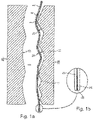
- Figure 1a shows the step of arranging a first embodiment of the Method according to the invention according to the first aspect of the invention, in which a preformed film layer structure 2 made of two plastic films 2a, 2c is arranged in a shaping tool 20a, 20b consisting of two tool halves.
- the step provided according to the invention of preforming the film layer structure 2 is not shown in detail, but results from the shaping of the preformed film layer structure 2.
- Figure 1a shows the tool 20a, 20b only in detail.
- a transparent adhesive layer 2b is provided in order to cohesively connect the two plastic films 2a, 2c.
- the film layer structure 2 has two main surfaces that are spaced apart in the stacking direction of its layers formed from plastic films 2a, 2c and an adhesive layer 2b, a first main surface 11 and a second main surface 12.
- the film layer structure 2 defines the greatest extent, the maximum extent I, of the entire plastic composite panel 1 , as later in figure 5 is shown.
- One of the two transparent plastic films 2a or 2c is coated with a metallic, translucent coating (thickness ⁇ 20 ⁇ m) in order to produce a shiny metallic light effect layer, with a semi-transparent (transmission approx. 5% to 25% in the more visible range) mirror effect being produced.
- the transparent plastic films 2a and 2c have additional transparent or translucent coatings, such as a protective lacquer coating.
- the coatings are in the Figure 1b not shown for reasons of scale and simplicity.
- the adhesive of the adhesive layer 2b is thermosetting and is also transparent.
- the overall thickness of the film layer structure 2 in the stacking direction of its layers is between 0.125 mm and 0.50 mm, for example.
- the specific shaping surface 21 is the final shape of the film layer structure 2 and is characterized in that it forms one or more three-dimensional contours 4 as elevations and/or depressions, which are formed from flat surfaces at an angle to one another and adjoining in straight edges 5, i.e. imitating the surface contour of a cut diamond.
- the roughness of the forming surface 21 is VDI 3400 Ref 12 or better.
- a cavity 8 is formed between the second main surface 12 facing away from the first main surface 11 and the surface 22 of the shaping tool 20a, 20b, whereas a remaining cavity 9 is formed between the first main surface 11 of the film layer structure 2 and the shaping surface 21 is to be reduced in the subsequent step.
- the remaining cavity 9 results from the fact that the film layer structure 2 was only preformed approximately to the final shape in the preforming step.
- the preforming step is necessary in order to ensure that the film layer structure 2 rests as completely as possible on the shaping surface 21 during the subsequent back-injection molding process, so that it can receive its final shape simulating the contour 4 or the contours.
- the preforming step is the in Figure 1a shown step upstream.
- the aim is to bring the film layer structure 2 into a shape by preforming that is not congruent with the final shape determined by the shaping tool 20a, 20b, in particular its shaping surface 21, but easier arranging of the film layer structure 2 in the shaping Tool 20a, 20b allows and ensures the achievement of the final shape.
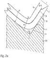
- the preformed film layer structure 2 has a radius of curvature R1 or R2 of the first main surface 11 of the film layer structure 2, which is brought about by preforming by means of the front edge of the preshaping surface, and which is introduced at a point that Edge 5 of the shaping surface 21 of the shaping tool 20a, 20b corresponds and is greater than the thickness d of the film layer structure 2 in each case. It also follows that the front edges of the preforming tool used to preform the film layer structure 2 have a larger radius than the corresponding edge 5 in the forming surface 21 of the forming tool 201, 20b due to the spatial placement, which has a radius r1 or r2 having.
- the three-dimensional pre-shaping effected by the pre-shaping is distinguished, for example, in a simple variant in that only the maximum heights and maximum depths of the pre-shaped shaping are formed at the points corresponding to the final shaping.
- the pre-shaping surface preferably also has edges, referred to here as front edges, which pre-shape the film layer structure 2 in such a way that at the points of the front edges it has a curvature with a radius that corresponds to at least twice the thickness of the film layer structure 2.
- the preforming surface is designed such that the leading edges placed at the corresponding location of the edges 5 of the forming surface 21 have a radius that is larger, preferably a multiple larger than the radius of the corresponding edge 5 of the forming surface 21 .
- thermoplastic 30 injected laterally according to the directional arrow V into the cavity 8 under pressure.
- the pressure of the thermoplastic ensures that the film layer structure 2 is adapted and embossed according to the profile of the shaping surface, while the temperature of the thermoplastic of, for example, approx. 300° C. and the temperature of the shaping tool of approx. 60° C. harden the adhesive of the adhesive layer 2b and thus a stabilization of the shaped film layer structure 2 causes.
- the thermoplastic 30 solidifies, the thermoplastic layer 3 is formed, which adjoins the second main surface 12 of the film layer structure 2 . After solidification, the thermoplastic layer 3 is bonded to the film layer structure 2 .
- the layered film structure has clung to the edges 5 of the contours 4 of the shaping surface 21.
- the layered structure obtained from the layered film structure 2 and the thermoplastic layer 3 is removed from the tool 20a after the thermoplastic has solidified and the adhesive has cured, i.e. the adhesive in the adhesive layer 2b has fully solidified , 20b taken to the in figure 5 plastic composite screen 1 according to the invention shown in a perspective view.
- the plastic composite panel 1 according to the invention is intended for use in a motor vehicle, not shown, and is arranged, for example, in a dashboard belonging to the vehicle or a center console and serves as a visually attractive, backlit display surface of a function display.
- the plastic composite panel 1 is elongate, so the film layer structure 2 belonging to the plastic composite panel 1 or its plastic films 2a, 2b has a maximum dimension I that exceeds the minimum dimension D of the plastic composite panel 1 many times over.
- the minimum dimension D is defined by the minimum thickness of the plastic composite panel 1, which is figure 4 is not shown entirely to scale. Your maximum expansion related to the film layer structure 2 is denoted by I and is more than 50 cm, such as 1 m.
- the minimum thickness D of the plastic composite panel 1 approximately in the stacking direction of its layers is in the range of 1 to 3 cm.
- the layer structure has a thermoplastic layer 3 which, when installed as intended, defines an outer surface 13 facing the vehicle occupant. Seen from the vehicle occupant, underneath the thermoplastic layer 3 is the film layer structure 2, which is cohesively connected to the film layer structure 2 by a thermal back-injection process.
- the film layer structure 2 has at least two plastic films 2a, 2c and at least one adhesive layer 2b which is arranged between each two plastic films 2a, 2c and connects the two plastic films 2a, 2c in a materially bonded manner, the film layer structure 2 defining two opposite outer main surfaces 11, 12 in the stacking direction of its layers, a first major face 11 defining an outer major face, ie an exposed surface, formed by the outer plastic film 2a of the film layer structure 2 or its coating if present, the aforesaid thermoplastic layer 3 adjoining the second major face 12.
- the film layer structure 2 is shaped in such a way that all surfaces and interfaces of the film layer structure 2, i.e.
- the plastic composite panel according to the invention thus imitates a surface structure of a polished diamond in an optically ideal manner. This is attributed to the use of a film layer structure 2 containing a plurality of plastic films and at least one adhesive layer, which perfectly accommodates and permanently retains the surface shape containing the contour 4 . In this way, the linear and sharp-edged edge profile typical of a polished diamond can be ideally reproduced, this is particularly advantageous if the contour 4 can be seen through the thermoplastic layer 3 when viewed.
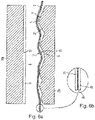
- Figure 6a shows the step of arranging a second embodiment of the method according to the invention, in which, in addition to a film layer structure 2 made of two plastic films 2a, 2c, an additional plastic film 6 made of a transparent thermoplastic is arranged in a shaping tool 20a, 20b consisting of two tool halves.
- Figure 6a shows the tool 20a, 20b only in detail.
- An adhesive layer 2b is provided between the two adjacent plastic films 2a, 2c of the film layer structure 2, as shown in detail in the enlarged representation in FIG. 5b, in order to bond the two plastic films 2a, 2c.
- the layered film structure 2 has two main surfaces that are spaced apart in the stacking direction of its layers formed from plastic films 2a, 2c and an adhesive layer 2b, a first main surface 11 and a second main surface 12.
- the layered film structure 2 defines the greatest extent, the maximum extent I, of the layered film structure 2 , as later in figure 9 is shown.
- the transparent plastic films 2a and 2c have additional transparent or translucent coatings, such as a protective lacquer coating or a metallic, non-conductive coating. The latter is intended to influence the optical reflection behavior of the film.
- the coatings are not shown in Figure 5b for reasons of scale and simplicity.
- the adhesive of the adhesive layer 2b is thermosetting and is also transparent.
- the overall thickness of the film layer structure 2 in the stacking direction of its layers is between 0.125 mm and 0.50 mm, for example.
- a cavity 8 is formed between the second main surface 12 facing away from the first main surface 11 and the surface 22 of the shaping tool 20a, 20b, whereas a remaining cavity 9 is formed between the first main surface 11 of the film layer structure 2 and the shaping surface 21 is to be reduced in the subsequent step.
- the remaining cavity 9 results from the fact that the film layer structure 2 was only preformed approximately to the final shape in the preforming step.
- a preforming step is necessary in order to ensure that the film layer structure 2 rests as completely as possible on the shaping surface 21 during the subsequent back-injection process, so that it can receive its final shape, which simulates the contour 4 or the contours.
- the preforming step is the in Figure 6a shown step upstream.
- the aim is to bring the film layer structure 2 into a shape by preforming that is not congruent with the final shape determined by the shaping tool 20a, 20b, in particular its shaping surface 21, but easier arranging of the film layer structure 2 in the shaping Tool 20a, 20b allows and ensures the achievement of the final shape.
- the three-dimensional preforming effected by the preforming is distinguished, for example, in a simple variant in that only the maximum heights and maximum depths of the preformed shape are formed at the points corresponding to the final shape.
- the preforming surface preferably also has edges, referred to here as front edges, which preform the film layer structure 2 in such a way that it has a curvature with a radius at the points of the front edges have, which corresponds to at least twice the thickness of the film layer structure 2.
- the preforming surface is designed such that the leading edges placed at the corresponding location of the edges 5 of the forming surface 21 have a radius that is larger, preferably a multiple larger than the radius of the corresponding edge 5 of the forming surface 21 .
- thermoplastic 30 is injected under pressure from the side in accordance with the directional arrow V into the cavity 8.
- the pressure of the thermoplastic ensures that the film layer structure 2 is adapted and embossed according to the profile of the shaping surface, while the temperature of the thermoplastic of, for example, approx. 300° C. and the temperature of the shaping tool of approx. 60° C. harden the adhesive of the adhesive layer 2b and thus a stabilization of the shaped film layer structure 2 causes.
- the thermoplastic 30 solidifies, the thermoplastic layer 3 is formed, which adjoins the second main surface 12 of the film layer structure 2 . After solidification, the thermoplastic layer 3 is bonded to the film layer structure 2 and to the additional plastic film 6 .
- the film layer structure 2 has clung to the edges 5 of the contours 4 of the shaping surface 21 .
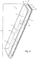
- the layer structure obtained from the film layer structure 2 and the thermoplastic layer 3 is removed from the tool 20a, 20b after the thermoplastic has solidified and cured, ie complete solidification of the adhesive of the adhesive layer 2b, in order to figure 9 plastic composite panel 1 according to the invention shown in a perspective view.
- the plastic composite panel 1 according to the invention is intended for use in a motor vehicle, not shown, and is arranged, for example, in a dashboard or a center console belonging to the vehicle and serves as a visually attractive backlit display area of a function display.
- the plastic composite panel 1 is elongate, so the film layer structure 2 belonging to the plastic composite panel 1 or its plastic films 2a, 2b has a maximum dimension I that exceeds the minimum dimension D of the plastic composite panel 1 many times over.
- the minimum dimension D is defined by the minimum thickness of the plastic composite panel 1 in the stacking direction of the layers or films of the plastic composite panel 1, which is figure 4 is not shown entirely to scale. Its maximum extension, based on the film layer structure 2, is denoted by I and is more than 50 cm, such as 1 m.
- the layer structure has an additional transparent plastic film 6 and a thermoplastic layer 3 which is arranged underneath and is materially bonded to the plastic film 6 .
- the additional plastic film defines an outer surface 13 facing the vehicle occupant.
- the film layer structure 2 Seen from the vehicle occupant, underneath the thermoplastic layer 3 is the film layer structure 2, which is bonded to the film layer structure 2 by a thermal back-injection process.
- the layered film structure 2 has at least two plastic films 2a, 2c and at least one adhesive layer 2b which is arranged between each two plastic films 2a, 2c and connects the two plastic films 2a, 2c in a materially bonded manner, with the layered film structure 2 defining two opposite outer main surfaces 11, 12 in the stacking direction of its layers , a first one of which is an outer main surface, ie an exposed surface defining main surface 11, which is formed by the outer plastic film 2a of the film layer structure 2 or if present its coating, the aforementioned thermoplastic layer 3 adjoining the second main surface 12.
- the film layer structure 2 is shaped in such a way that all surfaces and interfaces of the film layer structure 2, i.e.
- the plastic composite panel according to the invention thus imitates a surface structure of a polished diamond in an optically ideal manner. This is attributed to the use of a film layer structure 2 containing a plurality of plastic films and at least one adhesive layer, which perfectly accommodates and permanently retains the surface shape containing the contour 4 . In this way, the linear and sharp-edged edge profile typical of a polished diamond can be ideally reproduced. This is particularly advantageous if the contour 4 is recognizable when viewed through the additional plastic film 6 and the thermoplastic layer 3 .
Landscapes
- Engineering & Computer Science (AREA)
- Mechanical Engineering (AREA)
- Manufacturing & Machinery (AREA)
- Laminated Bodies (AREA)
Description
- Die Erfindung betrifft eine Kunststoffverbundblende mit einer Oberfläche, die die Oberfläche eines geschliffenen Diamanten imitiert sowie ein zugehöriges Herstellungsverfahren. Derzeit ist die Verwendung von aus Glaswerkstoffen bestehenden Blenden aus vielerlei Gründen bevorzugt. Einerseits lassen sich mit Glas mit hoher Präzision solche Oberflächen erzeugen, die eine geschliffene Oberfläche eines Diamanten imitieren, andererseits wird aufgrund der hohen Transparenz des Glaswerkstoffs und der Anmut der dadurch erzeugten Oberflächen eine solch Glasoberfläche vom Betrachter üblicherweise als sehr wertig empfunden. Nachteilig ist die vergleichsweise teure Herstellung sowie das Gewicht solcher Blenden, insbesondere wenn die Blende eine gewisse Dicke aufweisen muss, so dass die sich aus der Diamantstruktur ergebenden dreidimensionalen Oberflächenkonturen in die Blende integriert werden können. Andererseits ergibt sich aus der Bruchgefahr und der damit einhergehenden Splitterbildung ein nicht unerhebliches Verletzungsrisiko, so dass sich die Integration von aus ganz oder teilweise aus Glaswerkstoffen bestehenden Blenden in den Bereich des Armaturenbretts in Kraftfahrzeugen verbietet. Die Herstellung einer Blende aus Kunststoff birgt das Risiko, dass die Blende nicht über die gesamte Ausdehnung den gleichmäßigen Transparenzgrad erreicht, wie eine Blende aus einem Glaswerkstoff und beispielswese lokale Eintrübungen aufweist. Insbesondere die für eine realistisch wirkende Imitation der Diamantstruktur notwendige Nachbildung der scharfen Kantenübergänge ist meist nicht zu erreichen und lässt das Resultat oft nicht optisch attraktiv erscheinen.
- Ein Verfahren zur Herstellung einer Kunststoffverbundblende sowie eine zugehörige Kunststoffverbundblende gemäß der Oberbegriffe der Ansprüche 1 und 12 sind aus der
WO 2007/081915 A1 , derWO 2018/188939 A1 und derWO 2012/013631 A1 bekannt. - Vor diesem Hintergrund bestand Bedarf nach einem Verfahren zur Herstellung einer gattungsgemäßen Kunststoffverbundblende, die vergleichsweise leicht, haltbar ist und eine hochwertige Erscheinung aufweist, die denen aus Glaswerkstoffen zumindest nahekommt, die nach der Herstellung und in der Verwendung dauerhaft maßhaltig ist. Diese Aufgabe wird durch ein Herstellungsverfahren gemäß Anspruch 1 gelöst. Eine gleichermaßen vorteilhafte Verwendung sowie eine entsprechend vorteilhafte Kunststoffverbundblende sind jeweils Gegenstand der nebengeordneten Ansprüche. Vorteilhafte Ausgestaltungen sind jeweils Gegenstand der abhängigen Ansprüche. Es ist darauf hinzuweisen, dass die in den Ansprüchen einzeln aufgeführten Merkmale in beliebiger, technologisch sinnvoller Weise miteinander kombiniert werden können und weitere Ausgestaltungen der Erfindung aufzeigen. Die Beschreibung, insbesondere im Zusammenhang mit den Figuren, charakterisiert und spezifiziert die Erfindung zusätzlich.
- Die Erfindung betrifft ein Verfahren zur Herstellung einer einen Schichtaufbau aufweisenden Kunststoffverbundblende insbesondere für ein Kraftfahrzeug. Erfindungsgemäß ist ein Schritt des Bereitstellens vorgesehen, bei dem ein Folienschichtaufbau bereitgestellt wird, der mehreren transparente Kunststofffolien und zwischen zwei benachbarten Kunststofffolien des Folienschichtaufbaus angeordnete Klebstoffschicht aufweist, um die zwei Kunststofffolien zu verbinden, bevorzugt stoffschlüssig zu verbinden. Erfindungsgemäß ist die wenigstens eine Klebstoffschicht aus einem nicht vollständig verfestigten, aber zumindest im verfestigten Zustand transparenten Klebstoff ausgebildet. Der Folienschichtaufbau weist zwei sich in Stapelrichtung seiner aus Kunststofffolien und Klebstoffschicht gebildeten Schichten beabstandete Hauptflächen, eine erste und zweite Hauptfläche auf. Der Folienschichtaufbau definiert dabei die größte Ausdehnung. Der Begriff Kunststofffolie ist weit auszulegen, so dass eine zusätzliche Beschichtung nicht ausgeschlossen ist. Beispielsweise ist die Folie jeweils aus einem thermoplastischen Kunststoff, bevorzugt einem Polycarbonat oder einem Polymethylmethacrylat oder einem Polyethylenterephthalat ausgebildet. Erfindungsgemäß ist eine der Kunststofffolien transluzent metallisch beschichtet, bevorzugt nichtleitend metallisch beschichtet. Daraus ergibt sich beispielsweise eine dekorative, hauchdünne (Schichtdicke < 20µm) metallisch glänzende Lichteffektschicht, so dass ein semitransparenter (Transmission ca. 5% bis 25% im sichtbareren Bereich) Spiegeleffekt entsteht. Solche Schichten können beispielsweise durch physikalische Gasphasenabscheidung (englisch Physical Vapor Deposition, kurz PVD) oder, falls die Lichteffektschicht elektrisch nichtleitend sein soll, durch Kombination von PVD und Lack (NCVM - non conductive vapor metallization) erhalten werden. Jede der Kunststofffolien ist optional durch einen Rolle-zu-Rolle-Auftrag beschichtet. Beispielsweise ist wenigstens eine Kunststofffolie antireflex-, kratzfest- oder die Abriebfestigkeit steigernd beschichtet. Durch den Rolle-zu-Rolle Auftrag ist eine besonders gleichmäßige Beschichtung, mit entsprechenden gleichmäßigen optischen Eigenschaften möglich. Die Dicke des Folienschichtaufbaus in Stapelrichtung seiner Schichten bzw. Folien beträgt beispielsweise zwischen 0,125 mm bis 0,50 mm, bevorzugt 0,20 mm bis 0,30 mm.
- Erfindungsgemäß wird der bereitgestellte Folienschichtaufbau vorgeformt, so, dass dieser eine lediglich an eine endgültige Formgebung angenäherte Formgebung aufweist, also die angenäherte Formgebung nicht deckungsgleich mit der endgültigen Formgebung ist. Beispielsweise ist eine angenäherte Formgebung dann erreicht, wenn zumindest die örtliche Verteilung der Höhen und Tiefen über die Hauptflächen des Folienschichtaufbaus bei angenäherter und endgültiger Formgebung übereinstimmt. Bevorzugt handelt es sich bei dem Vorformen um ein thermisches Umformen und/oder isostatischen Hochdruckumformen des Folienschichtaufbaus. Beispielsweise wird ein beim Bereitstellen passend zugeschnittenes, ebenes Stück des Folienschichtaufbaus bereitgestellt und mittels des Vorformens dreidimensional vorgeformt.
- Nach dem Vorformen wird der vorgeformte Folienschichtaufbau in einem formgebenden Werkzeug angeordnet. Beim Anordnen des Folienschichtaufbaus in dem formgebenden Werkzeug ist dieser mit einer ersten seiner zwei Hauptflächen an eine spezifische formgebende Oberfläche des formgebenden Werkzeugs zugewandt angeordnet. Die spezifische, formgebende Oberfläche zeichnet sich dadurch aus, dass sie eine oder mehrere dreidimensionale Konturen als Erhebung und/oder Vertiefung ausbildet, die aus ebenen, gewinkelt zueinander stehenden, in geradlinigen Kanten aneinandergrenzenden Flächen gebildet ist, also insgesamt betrachtet die Oberflächenkontur eines oder mehrerer geschliffener Diamanten imitiert. Die Rauheit der formgebenden Oberfläche ist beispielsweise VDI 3400 Ref 12 oder besser.
- Bei dem Anordnen des Folienschichtaufbaus in dem formgebenden Werkzeug wird zwischen der der ersten Hauptfläche abgewandten, zweiten Hauptfläche und dem formgebenden Werkzeug eine Cavität ausgebildet, wohingegen die aus der lediglichen angenäherten Formgebung der Folienschichtaufbau resultierende verbleibende Cavität zwischen der ersten Hauptfläche des Folienschichtaufbaus und der formgebenden Oberfläche aufgrund fehlender vollflächiger angrenzender Anordnung der beiden, durch den nachfolgend erläuterten Hinterspritzschritt reduziert wird.
- Erfindungsgemäß erfolgt ein nachfolgendes Hinterspritzen des Folienschichtaufbaus in einem thermisch formgebenden Verfahrensschritt unter Einbringen eines spätestens im erstarrten Zustand transparenten Thermoplasts, wie Polycarbonat, in die erste Cavität, um den Schichtaufbau als Formling zu erzeugen und die angrenzende Annäherung, bevorzugt ein höheres Maß an Annäherung im Vergleich zur vorgeformten Formgebung, noch bevorzugter eine vollflächige Annäherung der ersten Hauptfläche des Folienschichtaufbaus an die formgebende Oberfläche zu bewirken. Anders ausgedrückt wird der Folienschichtaufbau bei diesem Vorgang ein weiteres Mal, wenn auch möglicherweise geringfügig, verformt und der Folienschichtaufbau übernimmt insbesondere die gewünschten scharfen, geradlinigen, von der formgebenden Oberfläche vorgegebenen Kanten zwischen zwei aneinandergrenzender im Wesentlichen ebenen Flächen. Der erhaltene Schichtaufbau weist wenigstens eine erste, äußere, zum Folienschichtaufbau gehörige Kunststofffolie, eine zweite, zum Folienschichtaufbau gehörige Kunststofffolie eine zwischen erster und zweiter Kunststofffolie sich erstreckende Klebstoffschicht und eine an eine zweite Hauptfläche des Folienschichtaufbaus angrenzende, durch den Thermoplast ausgebildete Thermoplastschicht auf.
- Beim Vorformen und/oder beim Hinterspritzen wird gleichzeitig ein Verfestigen der Klebstoffschicht bewirkt, wobei der Folienschichtaufbau entsprechend der spezifischen formgebenden Oberfläche ausgeformt stabilisiert wird. Als ein Verfestigen wird ein chemisches oder physikalisches Härten des Klebstoffs verstanden, was im Allgemeinen mit einem Viskositätsverlust einhergeht. Beispielsweise handelt es sich um einen wärmehärtenden Klebstoff oder die Verfestigung wird durch Bestrahlung, beispielsweise UV-Licht, bewirkt.
- Nach dem Erstarren der Thermoplastschicht wird der Folienschichtaufbau entnommen und zur Kunststoffverbundblende weiterverarbeitet oder als Kunststoffverbundblende montiert. Die erzeugte Kunststoffverbundblende imitiert in optisch idealer Weise die Diamantstruktur des formgebenden Werkzeugs. Es ist somit eine Kunststoffverbundblende mit idealen optischen Eigenschaften herstellbar. Dies wird auf die Verwendung eines mehrere Kunststofffolien und eine Klebstoffschicht beinhaltenden Folienschichtaufbaus als die Oberflächengestalt des formgebenden Werkzeugs primär aufnehmenden Bauteils der Kunststoffverbundblende zurückgeführt. Die optischen Eigenschaften der Kunststofffolien des Folienschichtaufbaus bleiben über deren Verlauf im Folienschichtaufbau trotz der Weiterverarbeitung im formgebenden Verfahren aufgrund der stabilisierenden Wirkung der Klebstoffschicht bzw. Klebstoffschichten erhalten. Ferner können optisch beeinflussende Beschichtungen, wie die Lichteffektschicht und/oder Lackschichten besonders gleichmäßig auf die Folien gegebenenfalls noch vor Erzeugen des Folienschichtaufbaus, also noch vor Verbinden der Folien mit den Klebeschichten auf die einzelne separierte Folie aufgebracht werden. Diese Aufbringung kann gegebenenfalls mit vergleichsweise einfachen Verfahren, wie ein Rolle-zu-Rolle-Auftrag auf die noch eben ausgerichtete Folie aufgebracht werden, ohne die gewünscht optisch attraktiven Eigenschaften im Gesamtaufbau der Kunststoffverbundblende zu gefährden.
- Gemäß einer bevorzugten Variante des Verfahrens erfolgt das Vorformen in einem vorformgebenden Werkzeug mit einer vorformgebenden Oberfläche, wobei diese, sofern sie nicht kantenfrei ist, nur solche Kanten, hier zur besseren Unterscheidung als Vorkanten bezeichnet, aufweist, die jeweils einen Radius aufweisen, der größer, bevorzugt ein Vielfaches größer als der Radius der entsprechenden Kante der formgebenden Oberfläche des zeitlich nachgeschalteten Hinterspritzschrittes ist. Anders ausgedrückt die Vorkanten der vorformenden Oberfläche sind gegenüber den an entsprechender Stelle angeordneten Kanten der formgebenden Oberfläche "verrundet". Es stellt sich somit in zwei Stufen am Ort der Kanten eine Krümmung im Folienschichtaufbau ein, was einerseits dafür sorgt, dass sich die endgültige Formgebung zuverlässig einstellt, die Kanten der endgültigen Formgebung vergleichsweise scharfkantig ausgebildet werden können, ohne die Gefahr fürchten zu müssen, dass die beim Vorformen erzeugten Krümmungen durch Fehlplatzierungen und/oder übermäßige Beanspruchung den Folienschichtaufbau irreversibel beschädigen.
- Noch bevorzugter beträgt der Radius aller Vorkanten der vorformgebenden Oberfläche mehr als das Doppelte, meist bevorzugt mehr als das Fünffache des größten Radius der Kanten der formgebenden Oberfläche.
- Gemäß einer bevorzugten Ausgestaltung weist auch die vorformgebende Oberfläche eine oder mehrere dreidimensionale Konturen als Erhebung und/oder Vertiefung auf, die aus ebenen, gewinkelt zueinanderstehenden, in geradlinigen Vorkanten aneinandergrenzenden Flächen gebildet ist, also insgesamt betrachtet die Oberflächenkontur eines oder mehrerer geschliffener Diamanten imitiert.
- Bevorzugt sind die Vorkanten so ausgebildet, beispielsweise deren Radius so gewählt, dass nach dem Vorformen des Folienschichtaufbaus an der der jeweiligen Vorkante entsprechender Stelle eine Krümmung der ersten Hauptfläche des Folienschichtaufbaus mit einem Radius bewirkt wird, der mindestens einer Dicker, bevorzugt mindestens dem Doppelten der Dicke des Folienschichtaufbaus entspricht.
- Dieser vergleichsweise große Radius ermöglicht später ein relativ einfaches und schnelles Positionieren des vorgeformten Folienschichtaufbaus in dem formgebenden, beim nachträglichen Hinterspritzen verwendeten Werkzeug.
- Das Hinterspritzen erfolgt bevorzugt unter bezogen auf die Stapelrichtung der Schichten des Schichtaufbaus seitlich, um optisch unattraktive Dichteschwankungen in der Thermoplastschicht zu vermeiden. "Seitlich" dabei meint eine Zufuhrrichtung, die mit der Stapelrichtung einen rechten Winkel oder einen vom rechten Winkel um maximal 20° abweichenden Winkel einschließt.
- Die Thermoplastschicht bildet bevorzugt eine ebene oder strukturierte, beschichtete oder unbeschichtete, äußere, noch bevorzugter freiliegende, dritte Hauptfläche des die Kunststoffverbundblende definierenden Schichtaufbaus aus. Bevorzugt und alternativ weist dabei die dritte Hauptfläche ebenfalls eine oder mehrere dreidimensionale Konturen auf, die jeweils aus ebenen, gewinkelt zueinanderstehenden, in geradlinigen Kanten aneinandergrenzenden, Flächen gebildet ist.
- Das Hinterspritzen des Folienschichtaufbaus kann mehrstufig erfolgen unter Verwendung eines weiteren formgebenden Werkzeugs. Beispielsweise wird nach dem Hinterspritzen des Folienschichtaufbaus mit einem ersten Thermoplast in einer ersten Stufe und nach dessen Erstarren der erhaltene Formling in ein weiteres formgebendes Werkzeug unter Ausbildung einer zwischen der äußeren Fläche der ersten Thermoplastschicht und dem weiteren formgebenden Werkzeug ausgebildeten weiteren Cavität verbracht. In einer zweiten Stufe wird ein zweiter Thermoplast in die weitere Cavität eingebracht, um eine zweite Thermoplastschicht auszubilden, wobei erste Thermoplastschicht und zweite Thermoplastschicht stoffschlüssig verbunden sind und eine gemeinsame innere Grenzfläche ausbilden.
- Bevorzugt ist der Klebstoff ein wärmehärtender Klebstoff und die Temperatur des Klebstoffs wird beim Vorformen, beispielsweise durch die Wahl der Temperatur des Werkzeugs, beispielsweise mehr als 280° C so eingestellt, dass eine Verfestigung bzw. Härten des Klebstoffs erreicht wird. Als eine Verfestigung wird beispielsweise chemisches und/oder physikalisches Härten des Klebstoffs, wie eine zunehmende Vernetzung des Klebstoffs verstanden. Dies hat den Vorteil, dass ein zusätzlicher Schritt Härteschritt entfallen kann.
- Gemäß einer bevorzugten Ausgestaltung des erfindungsgemäßen Verfahrens wird eine zusätzliche Kunststofffolie, bevorzugt aus einem transparenten Thermoplast, in dem formgebenden Werkzeug und daran angrenzend angeordnet, so dass die Cavität zwischen der zusätzlichen Kunststofffolie und dem Folienschichtaufbau ausgebildet ist und die zusätzliche Kunststofffolie eine äußere Kunststofffolie des Schichtaufbaus ist, um eine weitere optisch attraktive Oberfläche zu erzeugen. Bevorzugt weist dabei die an die zusätzliche Kunststofffolie angrenzende Oberfläche des formgebenden Werkzeugs ebenfalls eine oder mehrere dreidimensionale Konturen auf, die jeweils aus ebenen, gewinkelt zueinander stehenden, in geradlinigen Kanten aneinandergrenzenden Flächen gebildet ist.
- In einer zur vorgenannten Vorgehensweise zusätzlichen Vorgehensweise wird nach dem Entformen der Schichtaufbau in einem Gießformschritt mit einem Gießharz, bevorzugt einem polyurethanhaltigen Gießharz beschichtet. Bevorzugt weist dabei die an die Gießharzschicht angrenzende Oberfläche des formgebenden Werkzeugs ebenfalls eine oder mehrere dreidimensionale Konturen auf, die jeweils aus ebenen, gewinkelt zueinanderstehenden, in geradlinigen Kanten aneinandergrenzenden Flächen gebildet ist. Bevorzugt ist vorgesehen, dass die Gießharzschicht aus einem Polyurethan haltigen Gießharz ausgebildet ist, wobei das Polyurethan bevorzugt ein aliphatisches Polyurethan oder ein thermoplastisches Polyurethan ist. Das Gießharz kann ferner weitere Füllstoffe oder Additive aufweisen, beispielsweise Additive zur Verbesserung der Beständigkeit des Gießharzes gegenüber UV-Bestrahlung.
- Die Gießharzschicht kann dabei über den Verlauf eine variierende Dicke aufweisen oder aber eine annähernd gleichmäßige Dicke aufweisen. Beispielsweise beträgt die Maximaldicke der Gießharzschicht nicht mehr als 1/10 der maximalen Gesamtdicke des Schichtaufbaus der Kunststoffverbundblende in Stapelrichtung der Schichten. Beispielsweise beträgt die mittlere Dicke der Gießharzschicht 0,2 bis 3 mm. Bevorzugt beträgt die Maximaldicke der Gießharzschicht weniger als 1mm, bevorzugt weniger als 0,7 mm. Durch die im Vergleich zur Gesamtdicke des Schichtaufbaus der Kunststoffverbundblende nur geringe Dicke der Gießharzschicht, können Spannungseffekte innerhalb der Blende vermieden werden. Es können weitere Schritte zur Mikrobeschichtung oder Bearbeitung der Oberfläche der Gießharzschicht vorgesehen sein. Beispielsweise können zusätzliche Mikrobeschichtungen zur Erhöhung der Kraftfestigkeit auf die Oberfläche der Gießharzschicht aufgebracht werden. Als Mikrobeschichtungen werden solche Beschichtungen verstanden, die eine Schichtdicke von einigen bis einigen Dekaden Mikrometer aufweisen.
- Bevorzugt wird der Gießformschritt alternativ zum Schritt des Vorsehens der zusätzlichen Kunststofffolie gewählt, so dass die aus dem Gießharz ausgebildete Gießharzschicht angrenzend an die Thermoplastschicht angeordnet ist.
- Bevorzugt sind mindestens die Kunststofffolien des Folienschichtaufbaus aus einem transparenten Kunststoff ausgebildet, ist ferner die Klebstoffschicht aus einem transparenten oder zumindest transparent aushärtenden Klebstoff ausgebildet und der Thermoplast transparent, um die in den Folienschichtaufbau eingebrachte Kontur bei Betrachtung durch die Thermoplastschicht hindurch sichtbar zu machen. Bevorzugt weisen wenigstens die Kunststofffolien, die Klebstoffschicht und die Thermoplastschicht einen optischen Brechungsindex auf, wobei diese Brechungsindizes um nicht mehr als 0,2, bevorzugt 0,1, voneinander abweichen.
- Gemäß einer bevorzugten Variante weisen alle Schichten des Schichtaufbaus, bis auf eine optional vorgesehene metallische Beschichtung, einen Brechungsindex auf, der um nicht mehr als 0,2, bevorzugt 0,1 von dem der Thermoplastschicht abweicht. Bevorzugt Kunststofffolien, die Klebstoffschicht und die Thermoplastschicht die gleiche Farbe nach DIN 5033 auf, bzw. sind farblos oder unbunt. Dadurch kann eine optische "Tiefe" ähnlich dem eines Diamanten erzeugt werden.
- Bevorzugt beträgt der minimale Entformungswinkel der formgebenden Oberfläche des formgebenden Werkzeugs mehr als 3° beispielsweise 8°.
- Beispielsweise weist der Folienschichtaufbau drei Kunststofffolien und dazwischen liegende Klebstoffschichten auf, bevorzugt ist die Abfolge der Schichten des Folienschichtaufbaus wie folgt: transparente Lackschutzschicht; transparente Polycarbonatfolie mit einer Folienstärke von 125 µm; transparente Klebstoffschicht; einseitig metallisch, nicht-leitend transluzent (NCVM) beschichtete Polyethylenterephthalatfolie mit einer Folienstärke von 25 µm; transparente Klebstoffschicht; transparente Polycarbonatfolie mit einer Folienstärke von 125 µm; transparente Lackschutzschicht.
- Bevorzugt weisen die Kanten der formgebenden Oberfläche einen Radius zur Formgebung der ersten Hauptfläche des Folienschichtaufbaus von weniger als 0,1 mm, bevorzugt von gleich 0,08 mm oder weniger, vor.
- Gemäß einer bevorzugten Ausgestaltung des erfindungsgemäßen Verfahrens ist eine Maximalausdehnung des Folienschichtaufbaus um mindestens das 10-fache, bevorzugt mindestens das 20-fache, noch bevorzugter mindestens das 30-fache, größer als eine Minimalabmessung des Schichtaufbaus. Die Minimalabmessung bestimmt sich aus einem senkrecht zur Maximalausdehnung des Folienschichtaufbaus vorgenommenen Schnitt durch den Schichtaufbau der Kunststoffverbundblende, wobei die Minimalabmessung die minimalste Dicke dieses Schnitts ist.
- Die Erfindung betrifft ferner eine Kunststoffverbundblende in einem Schichtaufbau. Der Schichtaufbau der Kunststoffverbundblende umfasst einen Folienschichtaufbau aus wenigstens zwei transparenten Kunststofffolien und wenigstens einer, zwischen jeweils zwei Kunststofffolien angeordneten und die zwei Kunststofffolien jeweils stoffschlüssig verbindenden transparenten Klebstoffschicht, wobei der Folienschichtaufbau zwei in Stapelrichtung seiner Schichten gegenüberliegende äußere Hauptflächen definiert, von denen eine erste eine äußere Hauptfläche, d.h. eine freiliegende Oberfläche definierende Hauptfläche ist, die von einer der äußeren Kunststofffolien des Folienschichtaufbaus oder sofern vorhanden deren Beschichtung definiert ist und wobei wenigstens eine der Kunststofffolien transluzent metallisch beschichtet ist, um eine dekorative, metallisch glänzende Lichteffektschicht bereitzustellen.
- Beispielsweise ist eine Kunststofffolie des Folienschichtaufbaus durch Gasphasenabscheidung, wie chemische oder physikalische Gasphasenabscheidung oder Sputtern oder sogenanntes non conductive vacuum metallizing (NCVM) metallisch beschichtet. Beispielsweise ist die transluzent metallisch beschichtete Folie eine innere Folie des Folienschichtaufbaus und wirkt als Lichteffektschicht. Bevorzugt ist die metallisch transluzent beschichtete Folie elektrisch nichtleitend beschichtet, um bei späterer Anordnung der Kunststoffverbundblende vor einem kapazitiven oder induktiven Berühr- oder Annäherungsdetektionsmittel oder einer induktiven elektrischen Ladeinrichtung die elektromagnetische Feldausbreitung und damit die Detektion bzw. den Ladevorgang nicht zu stören.
- Der Schichtaufbau umfasst ferner eine an die zweite Hauptflächen des Folienschichtaufbaus angrenzend, bevorzugt vollflächig angrenzend, angeordnete Thermoplastschicht aus einem transparenten Thermoplast. Bevorzugt sind die Thermoplastschicht und der Folienschichtaufbau stoffschlüssig, beispielsweise durch Hinterspritzen verbunden. Dabei ist erfindungsgemäß der Folienschichtaufbau so geformt, dass alle Oberflächen und Grenzflächen des Folienschichtaufbaus, d.h. alle Oberflächen bzw. Grenzflächen zwischen den Kunststofffolien, deren optionale Beschichtungen und der Klebstoffschicht bzw. Klebstoffschichten eine oder mehrere, dreidimensionale Konturen ausbilden, die aus ebenen, gewinkelt zueinander stehenden, in geradlinigen Kanten aneinandergrenzenden Flächen gebildet ist. Die Kontur weist beispielsweise eine in Richtung der Thermoplastschicht weisende oder eine in entgegengesetzte Richtung weisende Spitze auf. Die erfindungsgemäße Kunststoffverbundblende imitiert somit in optisch idealer Weise eine Oberflächenstruktur eines oder mehrerer polierten Diamanten. Dies wird auf die Verwendung eines mehrere Kunststofffolien und eine Klebstoffschicht beinhaltenden Folienschichtaufbaus zurückgeführt, welche die die Kontur beinhaltende Oberflächengestalt in perfekter Weise aufnimmt und dauerhaft beibehält. Dadurch lässt sich insbesondere der geradlinige und scharfkantige für einen polierten Diamanten typische Kantenverlauf in idealer Weise nachbilden, dies ist insbesondere von Vorteil, wenn die Kontur bei Betrachtung durch die Thermoplastschicht hindurch erkennbar sein soll.
- Die Thermoplastschicht bildet bevorzugt eine ebene oder strukturierte, beschichtete oder unbeschichtete, äußere, noch bevorzugter freiliegende, dritte Hauptfläche des die Kunststoffverbundblende definierenden Schichtaufbaus aus. Bevorzugt weist die Oberfläche ebenfalls eine oder mehrere dreidimensionale Konturen auf, die jeweils aus ebenen, gewinkelt zueinanderstehenden, in geradlinigen Kanten aneinandergrenzenden Flächen gebildet ist
- Der Begriff Kunststofffolie ist weit auszulegen, so dass eine zusätzliche Beschichtung nicht ausgeschlossen ist. Beispielsweise ist die Folie jeweils aus einem thermoplastischen Kunststoff, bevorzugt einem Polycarbonat oder einem Polymethylmethacrylat oder einem Polyethylenterephthalat ausgebildet. Jede der Folie ist optional beschichtet, beispielsweise durch Gasphasenabscheidung oder durch einen Rolle-zu-Rolle-Auftrag. Beispielsweise ist wenigstens eine Kunststofffolie metallisch beschichtet, antireflex-, kratzfest- oder die Abriebfestigkeit steigernd beschichtet. Die Gesamtdicke des Folienschichtaufbaus in Stapelrichtung seiner Schichten beträgt beispielsweise zwischen 0,125 mm bis 0,50 mm, bevorzugt 0,20 mm bis 0,30 mm.
- Zur Verbesserung der optischen Attraktivität der äußeren Oberfläche der Kunststoffverbundblende auf der Seite der Kunststoffverbundblende, die dem Folienschichtaufbau gegenüberliegt, ist gemäß eine bevorzugten Ausführungsform der Kunststoffverbundblende eine zusätzliche Kunststofffolie auf der dem Folienschichtaufbau abgewandten Seite der Thermoplastschicht und/oder eine Gießharzschicht vorgesehen. Bevorzugt weist dabei die Oberfläche der Gießharzschicht ebenfalls eine oder mehrere dreidimensionale Konturen auf, die jeweils aus ebenen, gewinkelt zueinanderstehenden, in geradlinigen Kanten aneinandergrenzenden Flächen gebildet ist.
- Bevorzugt ist vorgesehen, dass die Gießharzschicht aus einem Polyurethan haltigen Gießharz ausgebildet ist, wobei das Polyurethan bevorzugt ein aliphatisches Polyurethan oder ein thermoplastisches Polyurethan ist. Das Gießharz kann ferner weitere Füllstoffe oder Additive aufweisen, beispielsweise Additive zur Verbesserung der Beständigkeit des Gießharzes gegenüber UV-Bestrahlung. Bevorzugt ist die zusätzliche Kunststofffolie aus einem transparenten Thermoplast bzw. ist die Gießharzschicht aus einem zumindest transparent aushärtendem Gießharz ausgebildet.
- Die Gießharzschicht kann dabei über den Verlauf eine variierende Dicke aufweisen oder aber eine annähernd gleichmäßige Dicke aufweisen. Beispielsweise beträgt die Maximaldicke der Gießharzschicht nicht mehr als 1/10 der maximalen Gesamtdicke des Schichtaufbaus der Kunststoffverbundblende in Stapelrichtung der Schichten. Beispielsweise beträgt die mittlere Dicke der Gießharzschicht 0,2 bis 3 mm. Bevorzugt beträgt die Maximaldicke der Gießharzschicht weniger als 1mm, bevorzugt weniger als 0,7 mm. Es können weitere Schritte zur Mikrobeschichtung oder Bearbeitung der Oberfläche der Gießharzschicht vorgesehen sein. Beispielsweise können zusätzliche Mikrobeschichtungen zur Erhöhung der Kraftfestigkeit auf die Oberfläche der Gießharzschicht aufgebracht werden. Als Mikrobeschichtungen werden solche Beschichtungen verstanden, die eine Schichtdicke von einigen bis einigen Dekaden Mikrometer aufweisen.
- Bevorzugt weisen wenigstens die Kunststofffolien, die Klebstoffschicht und die Thermoplastschicht einen optischen Brechungsindex auf, wobei diese Brechungsindizes um nicht mehr als 0,2, bevorzugt 0,1, voneinander abweichen. Gemäß einer bevorzugten Variante weisen alle Schichten des Schichtaufbaus, bis auf eine optional vorgesehene metallische Beschichtung, einen Brechungsindex auf, der um nicht mehr als 0,2, bevorzugt 0, 1 von dem der Thermoplastschicht abweicht. Bevorzugt weisen die Kunststofffolien, die Klebstoffschicht und die Thermoplastschicht die gleiche Farbe nach DIN 5033 auf, bzw. sind farblos oder unbunt. Dadurch kann eine optische "Tiefe" ähnlich dem eines Diamanten erzeugt werden.
- Beispielsweise weist der Folienschichtaufbau drei Kunststofffolien und dazwischen liegende Klebstoffschichten auf, bevorzugt ist die Abfolge der Schichten des Folienschichtaufbaus wie folgt: transparente Lackschutzschicht; transparente Polycarbonatfolie mit einer Folienstärke von 125 µm; transparente Klebstoffschicht; einseitig metallisch, nicht-leitend transluzent (NCVM) beschichtete Polyethylenterephthalatfolie mit einer Folienstärke von 25 µm; transparente Klebstoffschicht; transparente Polycarbonatfolie mit einer Folienstärke von 125 µm; transparente Lackschutzschicht.
- Bevorzugt weist die die freiliegende erste Hauptfläche des Folienschichtaufbaus definierende äußere, erste Kunststofffolie des Folienschichtaufbaus zur Ausbildung der Kanten der wenigstens einen Kontur einen Radius von weniger als 0,1 mm bevorzugt von gleich 0,08 mm oder weniger vor. Es ergibt sich ferner an den weiteren Schichten des Folienschichtaufbaus ein entsprechend größerer Radius, beispielsweise entspricht der Radius der die zweite Hauptfläche des Folienschichtaufbaus definierenden Kunststofffolie, welche nächstbenachbart zur Thermoplastschicht angeordnet ist, zur Ausbildung der Kanten in etwa der Schichtdicke des Folienschichtaufbaus und beträgt beispielsweise nicht mehr als 0,25 mm. Bevorzugt ist eine Maximalausdehnung des Folienschichtaufbaus um mindestens das 10-fache, bevorzugt mindestens das 20-fache, noch bevorzugter mindestens das 30-fache, größer als eine Minimalabmessung des Schichtaufbaus. Die Minimalabmessung bestimmt sich aus einem senkrecht zur Maximalausdehnung des Folienschichtaufbaus vorgenommenen Schnitt durch den Schichtaufbau der Kunststoffverbundblende, wobei die Minimalabmessung die minimalste Dicke dieses Schnitts ist.
- Die Erfindung betrifft ferner eine Anordnung aus der Kunststoffverbundblende in einer der zuvor beschriebenen Ausführungsformen und einem Leuchtmittel zur Hinterleuchtung oder Durchleuchtung der Kunststoffblende, wobei die erste Hauptfläche des Folienschichtaufbaus dem Leuchtmittel zugewandt ist. Die zweite Hauptfläche des Folienschichtaufbaus ist dem Betrachter zugewandt, wobei die dritte Hauptfläche, welche durch die Thermoplastschicht oder die zusätzliche Kunststofffolie oder die Gießharzschicht definiert ist, eine dem Betrachter zugewandte Oberfläche ausbildet.
- Die Erfindung betrifft ferner die Verwendung der Kunststoffverbundblende in einer der zuvor beschriebenen Ausführungsformen in einem Kraftfahrzeug.
- Die Erfindung wird anhand der nachfolgenden Figuren näher erläutert. Die Figuren sind dabei nur beispielhaft zu verstehen und stellen jeweils lediglich eine bevorzugte Ausführungsvariante dar.
-
- Fig. 1a
- eine schematische Schnittansicht eines Anordnungsschritt einer ersten Ausführungsform des erfindungsgemäßen Verfahrens zur Herstellung einer Kunststoffverbundblende;
- Fig. 1b
- eine zu
Fig 1a gehörige Detailvergrößerung; - Fig. 2a
- eine schematische Detailschnittansicht des in das formgebende Werkzeug angeordneten vorgeformten Folienschichtaufbaus 2;
- Fig. 2b
- eine weitere schematische Detailschnittansicht des in das formgebende Werkzeug angeordneten vorgeformten Folienschichtaufbaus 2;
- Fig. 3
- eine schematische Schnittansicht während des Hinterspritzschritts der ersten Ausführungsform des erfindungsgemäßen Verfahrens zur Herstellung der Kunststoffverbundblende;
- Fig. 4a
- eine schematische Schnittansicht vor dem Entformungsschritt der ersten Ausführungsform des erfindungsgemäßen Verfahrens zur Herstellung der Kunststoffverbundblende;
- Fig. 4b
- eine zu Fig 3a gehörige Detailvergrößerung;
- Fig. 5
- eine perspektivische Aufsicht auf die gemäß der ersten Ausführungsform des erfindungsgemäßen Verfahrens hergestellten Kunststoffverbundblende 1;
- Fig. 6a
- eine schematische Schnittansicht eines Anordnungsschritt einer zweiten Ausführungsform des erfindungsgemäßen Verfahrens zur Herstellung einer Kunststoffverbundblende;
- Fig. 6b
- eine zu
Fig 6a gehörige Detailvergrößerung; - Fig. 7
- eine schematische Schnittansicht während des Hinterspritzschritts der zweiten Ausführungsform des erfindungsgemäßen Verfahrens zur Herstellung der Kunststoffverbundblende;
- Fig. 8a
- eine schematische Schnittansicht vor dem Entformungsschritt der zweiten Ausführungsform des erfindungsgemäßen Verfahrens zur Herstellung der Kunststoffverbundblende;
- Fig. 8b
- eine zu
Fig 8a gehörige Detailvergrößerung; - Fig. 9
- eine perspektivische Aufsicht auf die gemäß der zweiten Ausführungsform des erfindungsgemäßen Verfahrens hergestellten Kunststoffverbundblende 1.
-
Figur 1a zeigt den Schritt des Anordnens einer ersten Ausführungsform des erfindungsgemäßen Verfahrens gemäß dem ersten Aspekt der Erfindung, bei dem ein vorgeformter Folienschichtaufbau 2 aus zwei Kunststofffolien 2a, 2c in einem formgebenden, aus zwei Werkzeughälften bestehenden Werkzeug 20a, 20b angeordnet wird. Der erfindungsgemäß vorgesehene Schritt des Vorformens des Folienschichtaufbaus 2 ist im Detail nicht dargestellt, sondern ergibt sich aus der Formgebung des vorgeformten Folienschichtaufbaus 2. -
Figur 1a zeigt das Werkzeug 20a, 20b nur im Ausschnitt. Zwischen den zwei benachbarten transparenten Kunststofffolien 2a, 2c des Folienschichtaufbaus 2 ist, wie im Detail in der vergrößerten Darstellung inFigur 1b gezeigt ist, eine transparente Klebstoffschicht 2b vorgesehen, um die zwei Kunststofffolien 2a, 2c stoffschlüssig zu verbinden. Der Folienschichtaufbau 2 weist zwei sich in Stapelrichtung seiner aus Kunststofffolien 2a, 2c und einer Klebstoffschicht 2b gebildeten Schichten beabstandete Hauptflächen auf, eine erste Hauptfläche 11 und eine zweite Hauptfläche 12. Der Folienschichtaufbau 2 definiert die größte Ausdehnung, die Maximalausdehnung I, der gesamten Kunststoffverbundblende 1, wie später inFigur 5 gezeigt ist. Eine der beiden transparenten Kunststofffolien 2a oder 2c ist mit einer metallischen, transluzenten Beschichtung (Schichtdicke < 20µm) beschichtet, um eine metallisch glänzende Lichteffektschicht zu erzeugen, wobei ein semitransparenter (Transmission ca. 5% bis 25% im sichtbareren Bereich) Spiegeleffekt hervorgerufen wird. Die transparenten Kunststofffolien 2a und 2c weisen zusätzliche transparente oder transluzente Beschichtungen, wie eine Schutzlackbeschichtung auf. Die Beschichtungen sind in derFigur 1b aus Gründen der Maßstäblichkeit und der Vereinfachung nicht gezeigt. Der Klebstoff der Klebstoffschicht 2b ist wärmehärtend und ist ebenfalls transparent. Die Gesamtdicke des Folienschichtaufbaus 2 in Stapelrichtung seiner Schichten liegt beispielsweise zwischen 0,125 mm bis 0,50 mm. Beim Anordnen des vorgeformten Folienschichtaufbaus 2 in dem formgebenden Werkzeug 20a, 20b wird dieser so platziert, dass eine seiner zwei Hauptflächen, hier die erste Hauptfläche 11, einer spezifischen formgebenden Oberfläche 21 des formgebenden Werkzeugs 20a, 20b zugewandt ist und damit die zweite Hauptfläche 12 der formgebenden Oberfläche 21 abgewandt ist. Die spezifische formgebende Oberfläche 21 soll die endgültige Formgebung des Folienschichtaufbaus 2 vorgeben und ist dadurch charakterisiert, dass sie eine oder mehrere dreidimensionale Konturen 4 als Erhebung und/oder Vertiefung ausbildet, die aus ebenen, gewinkelt zueinander stehenden, in geradlinigen Kanten 5 aneinandergrenzenden Flächen gebildet ist, also die Oberflächenkontur eines geschliffenen Diamanten imitiert. Die Rauheit der formgebenden Oberfläche 21 ist VDI 3400 Ref 12 oder besser. - Bei dem Anordnen des Folienschichtaufbaus 2 in dem formgebenden Werkzeug 20a, 20b wird zwischen der der ersten Hauptfläche 11 abgewandten, zweiten Hauptfläche 12 und der Fläche 22 des formgebenden Werkzeug 20a, 20b eine Cavität 8 ausgebildet, wohingegen eine verbleibende Cavität 9 zwischen der ersten Hauptfläche 11 des Folienschichtaufbaus 2 und der formgebenden Oberfläche 21 im nachfolgenden Schritt reduziert werden soll. Die verbleibende Cavität 9 ergibt sich daraus, dass der Folienschichtaufbau 2 im Vorformschritt lediglich an die endgültige Formgebung angenähert vorgeformt wurde. Der Vorformschritt ist andererseits nötig, um beim nachfolgenden Hinterspritzen ein möglichst vollständiges Anliegen des Folienschichtaufbaus 2 an die formgebende Oberfläche 21 zu erreichen, so dass dieser seine, die Kontur 4 oder die Konturen nachbildende, endgültige Formgebung erhalten kann. Dabei handelt es sich um einen Warmumformungs- und/oder einen isostatischen Hochdruckumformungsschritt in einem vorformgebenden Werkzeug, welches eine vorformgebende Oberfläche aufweist. Der Vorformschritt ist dem in
Figur 1a gezeigten Schritt vorgeschaltet. Dabei geht es darum, den Folienschichtaufbau 2 durch das Vorformen in eine Formgebung zu bringen, die nicht deckungsgleich mit der endgültigen, durch das formgebende Werkzeug 20a, 20b, insbesondere dessen formgebende Oberfläche 21 bestimmte Formgebung ist, aber ein leichteres Anordnen des Folienschichtaufbaus 2 im formgebenden Werkzeug 20a, 20b ermöglicht und das Erreichen der endgültigen Formgebung sicherstellt. - Eine exakte Übereinstimmung der vorgeformten Formgebung an die endgültige Formgebung ist aus mehreren Gründen nicht erwünscht, so wird dadurch nicht nur die positionsgenaue Anordnung im formgebenden Werkzeug 20a, 20b erschwert, sondern es besteht die Gefahr, dass die beim Vorformen ansonsten möglicherweise bereits in den Folienschichtaufbau eingebrachten Kanten nicht exakt deckungsgleich mit den Kanten im formgebenden Werkzeug 20a, 20b sind, was zu einer Beeinträchtigung der optischen Erscheinung des gesamten Schichtaufbaus führt. Aus diesem Grund wird zumindest auf eine Ausbildung von scharfen Kanten im Folienschichtaufbau 2 im Vergleich zu denen der endgültigen Formgebung verzichtet. Anders ausgedrückt, die Vorkanten der vorformgebenden Oberfläche sind gegenüber den Kanten 5 der formgebenden Oberfläche 21 verrundet. Wie die
Figuren 2a und2b an einer Senke bzw. Spitze der formgebenden Oberfläche 21 zeigen, weist der vorgeformte Folienschichtaufbau 2 einen durch das Vorformen mittels der Vorkante der vorformgebenden Oberfläche bewirkten Krümmungsradius R1 beziehungsweise R2 der ersten Hauptfläche 11 des Folienschichtaufbaus 2 auf, der an einer Stelle eingebracht ist, die einer Kante 5 der formgebenden Oberfläche 21 des formgebenden Werkzeugs 20a, 20b entspricht und dabei jeweils größer als die Dicke d des Folienschichtaufbaus 2 ist. Es ergibt sich daraus ferner, dass die zum Vorformen des Folienschichtaufbaus 2 verwendeten Vorkanten des vorformgebenden Werkzeugs einen größeren Radius aufweisen als die aufgrund der räumlichen Platzierung entsprechende Kante 5 in der formgebenden Oberfläche 21 des formgebenden Werkzeugs 201, 20b, welche einen Radius r1 bzw. r2 aufweist. - Die durch das Vorformen bewirkte dreidimensionale Vorformung zeichnet sich beispielsweise in einer einfachen Variante dadurch aus, dass lediglich die maximalen Höhen und maximalen Tiefen der vorgeformten Formgebung an den der endgültigen Formgebung entsprechenden Stellen ausgebildet werden. Bevorzugt weist aber auch die vorformgebende Oberfläche Kanten, hier als Vorkanten bezeichnet, auf, die den Folienschichtaufbau 2 so vorformen, dass dieser an den Stellen der Vorkanten eine Krümmung mit einem Radius aufweisen, der mindestens dem Doppelten der Dicke des Folienschichtaufbaus 2 entspricht. Die vorformgebende Oberfläche ist so ausgebildet, dass die an entsprechender Stelle der Kanten 5 der formgebenden Oberfläche 21 platzierten Vorkanten einen Radius aufweisen, der größer, bevorzugt ein Vielfaches größer als der Radius der entsprechenden Kante 5 der formgebenden Oberfläche 21 ist.
- Im nachfolgenden Hinterspritzschritt der
Figur 3 wird das Werkzeug 20a, 20b geschlossen und ein Thermoplast 30 seitlich entsprechend dem Richtungspfeil V in die Cavität 8 unter Druck eingespritzt. Dies sorgt dafür, dass der Folienschichtaufbau 2 sich an die formgebende Oberfläche 21 anlegt und dessen Profil also die dreidimensionalen Konturen 4 als Negativabdruck übernimmt. Der Druck des Thermoplasts sorgt für eine Anpassung und Prägung des Folienschichaufbaus 2 entsprechend dem Profil der formgebenden Oberfläche, während die Temperatur des Thermoplasts von beispielsweise ca. 300°C und die Temperatur des formgebenden Werkzeugs von ca. 60°C ein Härten des Klebstoffs der Klebstoffschicht 2b und damit eine Stabilisierung des ausgeformten Folienschichtaufbaus 2 bewirkt. Nach erfolgter Ausfüllung der Cavität 8 ist der inFigur 4a gezeigte Zustand erreicht. Mit dem Erstarren des Thermoplasts 30 ist die Thermoplastschicht 3 ausgebildet, die an die zweite Hauptfläche 12 des Folienschichtaufbaus 2 angrenzt. Nach dem Erstarren ist die Thermoplastschicht 3 stoffschlüssig mit dem Folienschichtaufbau 2 verbunden. - Wie
Figur 4b zeigt, hat sich der Folienschichtaufbau an die Kanten 5 der Konturen 4 der formgebenden Oberfläche 21 angeschmiegt Der erhaltene Schichtaufbau aus dem Folienschichtaufbau 2 und der Thermoplastschicht 3 wird nach dem Erstarren des Thermoplasts und dem Aushärten, d.h. vollständigen Verfestigen des Klebstoffs der Klebstoffschicht 2b dem Werkzeug 20a, 20b entnommen, um die inFigur 5 in perspektivischer Aufsicht gezeigte, erfindungsgemäße Kunststoffverbundblende 1 zu erhalten. - Die erfindungsgemäße Kunststoffverbundblende 1 ist zur Verwendung in einem nicht dargestellten Kraftfahrzeug vorgesehen und beispielsweise in einem zum Fahrzeug gehörenden Armaturenbrett oder einer Mittelkonsole angeordnet und dient als optisch attraktive, hinterleuchtete Anzeigefläche einer Funktionsanzeige. Die Kunststoffverbundblende 1 ist länglich ausgebildet, somit weist der zur Kunststoffverbundblende 1 gehörige Folienschichtaufbau 2 bzw. dessen Kunststofffolien 2a, 2b eine Maximalabmessung I auf, die die Minimalabmessung D der Kunststoffverbundblende 1 um ein Vielfaches übersteigt. Die Minimalabmessung D ist durch die minimalste Dicke der Kunststoffverbundblende 1 definiert, was in
Figur 4 nicht ganz maßstabsgetreu dargestellt ist. Ihre auf den Folienschichtaufbau 2 bezogene Maximalausdehnung ist mit I bezeichnet und beträgt mehr als 50cm, wie beispielsweise 1 m. Die minimalste Dicke D der Kunststoffverbundblende 1 in etwa in Stapelrichtung ihrer Schichten liegt im Bereich 1 bis 3 cm. Der Schichtaufbau weist eine Thermoplastschicht 3 auf, die bei bestimmungsgemäßer Montage eine dem Fahrzeuginsassen zugewandte äußere Oberfläche 13 definiert. Vom Fahrzeuginsassen aus gesehen, befindet sich unter der Thermoplastschicht 3 der Folienschichtaufbau 2, der durch einen thermischen Hinterspritzvorgang stoffschlüssig mit dem Folienschichtaufbau 2 verbunden ist. Der Folienschichtaufbau 2 weist wenigstens zwei Kunststofffolien 2a, 2c und wenigstens eine zwischen jeweils zwei Kunststofffolien 2a, 2c angeordnete und die zwei Kunststofffolien 2a, 2c stoffschlüssig verbindende Klebstoffschicht 2b , wobei der Folienschichtaufbau 2 zwei in Stapelrichtung seiner Schichten gegenüberliegende äußere Hauptflächen 11, 12 definiert, von denen eine erste eine äußere Hauptfläche, d.h. eine freiliegende Oberfläche definierende Hauptfläche 11 ist, die von der äußeren Kunststofffolien 2a des Folienschichtaufbaus 2 oder sofern vorhanden deren Beschichtung ausgebildet ist, wobei die vorgenannte Thermoplastschicht 3 an die zweite Hauptfläche 12 angrenzt. Dabei ist erfindungsgemäß der Folienschichtaufbau 2 so geformt, dass alle Oberflächen und Grenzflächen des Folienschichtaufbaus 2, d.h. alle Oberflächen bzw. Grenzflächen zwischen den Kunststofffolien 2a, 2c, deren optionale Beschichtungen und der Klebstoffschicht 2b eine oder mehrere, dreidimensionale Konturen 4 nahezu deckungsgleich ausbilden, die aus ebenen, gewinkelt zueinander stehenden, in geradlinigen Kanten 5 aneinandergrenzenden Flächen gebildet ist. Die Kontur 4 weist beispielsweise eine in Richtung der Thermoplastschicht 3 weisende oder eine in entgegengesetzte Richtung weisende Spitze auf. Die erfindungsgemäße Kunststoffverbundblende imitiert somit in optisch idealer Weise eine Oberflächenstruktur eines polierten Diamanten. Dies wird auf die Verwendung eines mehrere Kunststofffolien und wenigstens eine Klebstoffschicht beinhaltenden Folienschichtaufbaus 2 zurückgeführt, welche die die Kontur 4 beinhaltende Oberflächengestalt in perfekter Weise aufnimmt und dauerhaft beibehält. Dadurch lässt sich insbesondere der geradlinige und scharfkantige für einen polierten Diamanten typische Kantenverlauf in idealer Weise nachbilden, dies ist insbesondere von Vorteil, wenn die Kontur 4 bei Betrachtung durch die Thermoplastschicht 3 hindurch erkennbar wird. -
Figur 6a zeigt den Schritt des Anordnens einer zweiten Ausführungsform des erfindungsgemäßen Verfahrens, bei dem neben einem Folienschichtaufbau 2 aus zwei Kunststofffolien 2a, 2c eine zusätzliche Kunststofffolie 6 aus einem transparentem Thermoplast in einem formgebenden, aus zwei Werkzeughälften bestehenden Werkzeug 20a, 20b angeordnet wird.Figur 6a zeigt das Werkzeug 20a, 20b nur im Ausschnitt. Zwischen den zwei benachbarten Kunststofffolien 2a, 2c des Folienschichtaufbaus 2 ist, wie im Detail in der vergrößerten Darstellung in Figur 5b gezeigt ist, eine Klebstoffschicht 2b vorgesehen, um die zwei Kunststofffolien 2a, 2c stoffschlüssig zu verbinden. Der Folienschichtaufbau 2 weist zwei, sich in Stapelrichtung seiner aus Kunststofffolien 2a, 2c und einer Klebstoffschicht 2b gebildeten Schichten beabstandete Hauptflächen auf, eine erste Hauptfläche 11 und eine zweite Hauptfläche 12. Der Folienschichtaufbau 2 definiert die größte Ausdehnung, die Maximalausdehnung I, des Folienschichtaufbaus 2, wie später inFigur 9 gezeigt ist. Die transparenten Kunststofffolien 2a und 2c weisen zusätzliche transparente oder transluzente Beschichtungen, wie eine Schutzlackbeschichtung oder eine metallische, nichtleitende Beschichtung. Letztere ist vorgesehen, das optische Reflexionsverhalten der Folie zu beeinflussen. Die Beschichtungen sind in der Figur 5b aus Gründen der Maßstäblichkeit und der Vereinfachung nicht gezeigt. Der Klebstoff der Klebstoffschicht 2b ist wärmehärtend und ist ebenfalls transparent. Die Gesamtdicke des Folienschichtaufbaus 2 in Stapelrichtung seiner Schichten beträgt beispielsweise zwischen 0,125 mm bis 0,50 mm. - Bei dem Anordnen des Folienschichtaufbaus 2 in dem formgebenden Werkzeug 20a, 20b wird zwischen der der ersten Hauptfläche 11 abgewandten, zweiten Hauptfläche 12 und der Fläche 22 des formgebenden Werkzeug 20a, 20b eine Cavität 8 ausgebildet, wohingegen eine verbleibende Cavität 9 zwischen der ersten Hauptfläche 11 des Folienschichtaufbaus 2 und der formgebenden Oberfläche 21 im nachfolgenden Schritt reduziert werden soll. Die verbleibende Cavität 9 ergibt sich daraus, dass der Folienschichtaufbau 2 im Vorformschritt lediglich an die endgültige Formgebung angenähert vorgeformt wurde. Der Vorformschritt ist andererseits nötig, um beim nachfolgenden Hinterspritzen ein möglichst vollständiges Anliegen des Folienschichtaufbaus 2 an die formgebende Oberfläche 21 zu erreichen, so dass dieser seine, die Kontur 4 oder die Konturen nachbildende, endgültige Formgebung erhalten kann. Dabei handelt es sich um einen Warmumformungs- und/oder einen isostatischen Hochdruckumformungsschritt in einem vorformgebenden Werkzeug, welches eine vorformgebende Oberfläche aufweist. Der Vorformschritt ist dem in
Figur 6a gezeigten Schritt vorgeschaltet. Dabei geht es darum, den Folienschichtaufbau 2 durch das Vorformen in eine Formgebung zu bringen, die nicht deckungsgleich mit der endgültigen, durch das formgebende Werkzeug 20a, 20b, insbesondere dessen formgebende Oberfläche 21 bestimmte Formgebung ist, aber ein leichteres Anordnen des Folienschichtaufbaus 2 im formgebenden Werkzeug 20a, 20b ermöglicht und das Erreichen der endgültigen Formgebung sicherstellt. - Eine exakte Übereinstimmung der vorgeformten Formgebung an die endgültige Formgebung ist aus mehreren Gründen nicht erwünscht, so wird dadurch nicht nur die positionsgenaue Anordnung im formgebenden Werkzeug 20a, 20b erschwert, sondern es besteht die Gefahr, dass die beim Vorformen ansonsten möglicherweise bereits in den Folienschichtaufbau eingebrachten Kanten nicht exakt deckungsgleich mit den Kanten im formgebenden Werkzeug 20a, 20b sind, was zu einer Beeinträchtigung der optischen Erscheinung des gesamten Schichtaufbaus führt. Aus diesem Grund wird zumindest auf eine Ausbildung von scharfen Kanten im Folienschichtaufbau 2 im Vergleich zu denen der endgültigen Formgebung verzichtet. Anders ausgedrückt, die Vorkanten der vorformgebenden Oberfläche sind gegenüber den Kanten 5 der formgebenden Oberfläche 21 verrundet.
- Die durch das Vorformen bewirkte dreidimensionale Vorformung zeichnet sich beispielsweise in einer einfachen Variante dadurch aus, dass lediglich die maximalen Höhen und maximalen Tiefen der vorgeformten Formgebung an den der endgültigen Formgebung entsprechenden Stellen ausgebildet werden. Bevorzugt weist aber auch die vorformgebende Oberfläche Kanten, hier als Vorkanten bezeichnet, auf, die den Folienschichtaufbau 2 so vorformen, dass dieser an den Stellen der Vorkanten eine Krümmung mit einem Radius aufweisen, der mindestens dem Doppelten der Dicke des Folienschichtaufbaus 2 entspricht. Die vorformgebende Oberfläche ist so ausgebildet, dass die an entsprechender Stelle der Kanten 5 der formgebenden Oberfläche 21 platzierten Vorkanten einen Radius aufweisen, der größer, bevorzugt ein Vielfaches größer als der Radius der entsprechenden Kante 5 der formgebenden Oberfläche 21 ist.
- Im nachfolgenden Hinterspritzschritt der
Figur 7 wird das Werkzeug 20a, 20b geschlossen und ein transparenter Thermoplast 30 seitlich entsprechend dem Richtungspfeil V in die Cavität 8 unter Druck eingespritzt. Dies sorgt dafür, dass der Folienschichtaufbau 2 sich an die formgebende Oberfläche 21 anlegt und dessen Profil also die dreidimensionalen Konturen 4 als Negativabdruck übernimmt. Der Druck des Thermoplasts sorgt für eine Anpassung und Prägung des Folienschichaufbaus 2 entsprechend dem Profil der formgebenden Oberfläche, während die Temperatur des Thermoplasts von beispielsweise ca. 300°C und die Temperatur des formgebenden Werkzeugs von ca. 60°C ein Härten des Klebstoffs der Klebstoffschicht 2b und damit eine Stabilisierung des ausgeformten Folienschichtaufbaus 2 bewirkt. Nach erfolgter Ausfüllung der Cavität 8 ist der inFigur 8a gezeigte Zustand erreicht. Mit dem Erstarren des Thermoplasts 30 ist die Thermoplastschicht 3 ausgebildet, die an die zweite Hauptfläche 12 des Folienschichtaufbaus 2 angrenzt. Nach dem Erstarren ist die Thermoplastschicht 3 stoffschlüssig mit dem Folienschichtaufbau 2 sowie mit der zusätzlichen Kunststofffolie 6 verbunden. - Wie
Figur 8b zeigt, hat sich der Folienschichtaufbau 2 an die Kanten 5 der Konturen 4 der formgebenden Oberfläche 21 angeschmiegt. Der erhaltene Schichtaufbau aus dem Folienschichtaufbau 2 und der Thermoplastschicht 3 wird nach dem Erstarren des Thermoplasts und dem Aushärten, d.h. vollständigen Verfestigen des Klebstoffs der Klebstoffschicht 2b dem Werkzeug 20a, 20b entnommen, um die inFigur 9 in perspektivischer Aufsicht gezeigte erfindungsgemäße Kunststoffverbundblende 1 zu erhalten. - Die erfindungsgemäße Kunststoffverbundblende 1 ist zur Verwendung in einem nicht dargestellten Kraftfahrzeug vorgesehen und beispielsweise in einem zum Fahrzeug gehörenden Armaturenbrett oder einer Mittelkonsole angeordnet und dient als optisch attraktiven hinterleuchtete Anzeigefläche einer Funktionsanzeige. Die Kunststoffverbundblende 1 ist länglich ausgebildet, somit weist der zur Kunststoffverbundblende 1 gehörige Folienschichtaufbau 2 bzw. deren Kunststofffolien 2a, 2b eine Maximalabmessung I auf, die die Minimalabmessung D der Kunststoffverbundblende 1 um ein Vielfaches übersteigt. Die Minimalabmessung D ist durch die minimalste Dicke der Kunststoffverbundblende 1 in Stapelrichtung der Schichten bzw. Folien der Kunststoffverbundblende 1 definiert, was in
Figur 4 nicht ganz maßstabsgetreu dargestellt ist. Ihre auf den Folienschichtaufbau 2 bezogene Maximalausdehnung ist mit I bezeichnet und beträgt mehr als 50cm, wie beispielsweise 1 m. Die minimalste Dicke D der Kunststoffverbundblende 1 in Stapelrichtung ihrer Schichten liegt im Bereich 1 bis 3 cm. Der Schichtaufbau weist eine zusätzliche transparente Kunststofffolie 6 und eine darunter angeordnete, mit der Kunststofffolie 6 stoffschlüssig verbundene Thermoplastschicht 3 auf. Die zusätzliche Kunststofffolie definiert bei bestimmungsgemäßer Montage eine dem Fahrzeuginsassen zugewandte äußere Oberfläche 13. Vom Fahrzeuginsassen aus gesehen, befindet sich unter der Thermoplastschicht 3 der Folienschichtaufbau 2, der durch einen thermischen Hinterspritzvorgang stoffschlüssig mit dem Folienschichtaufbau 2 verbunden ist. Der Folienschichtaufbau 2 weist wenigstens zwei Kunststofffolien 2a, 2c und wenigstens eine zwischen jeweils zwei Kunststofffolien 2a, 2c angeordnete und die zwei Kunststofffolien 2a, 2c stoffschlüssig verbindende Klebstoffschicht 2b, wobei der Folienschichtaufbau 2 zwei in Stapelrichtung seiner Schichten gegenüberliegende, äußere Hauptflächen 11, 12 definiert, von denen eine erste eine äußere Hauptfläche, d.h. eine freiliegende Oberfläche definierende Hauptfläche 11 ist, die von der äußeren Kunststofffolien 2a des Folienschichtaufbaus 2 oder sofern vorhanden deren Beschichtung ausgebildet ist, wobei die vorgenannte Thermoplastschicht 3 and die zweite Hauptfläche 12 angrenzt. Dabei ist erfindungsgemäß der Folienschichtaufbau 2 so geformt, dass alle Oberflächen und Grenzflächen des Folienschichtaufbaus 2, d.h. alle Oberflächen bzw. Grenzflächen zwischen den Kunststofffolien 2a, 2c, deren optionale Beschichtungen und der Klebstoffschicht 2b eine oder mehrere, dreidimensionale Konturen 4 nahezu deckungsgleich ausbilden, die aus ebenen, gewinkelt zueinander stehenden, in geradlinigen Kanten 5 aneinandergrenzenden Flächen gebildet ist. Die Kontur 4 weist beispielsweise eine in Richtung der Thermoplastschicht 3 weisende oder eine in entgegengesetzte Richtung weisende Spitze auf. Die erfindungsgemäße Kunststoffverbundblende imitiert somit in optisch idealer Weise eine Oberflächenstruktur eines polierten Diamanten. Dies wird auf die Verwendung eines mehrere Kunststofffolien und wenigstens eine Klebstoffschicht beinhaltenden Folienschichtaufbaus 2 zurückgeführt, welche die die Kontur 4 beinhaltende Oberflächengestalt in perfekter Weise aufnimmt und dauerhaft beibehält. Dadurch lässt sich insbesondere der geradlinige und scharfkantige für einen polierten Diamanten typische Kantenverlauf in idealer Weise nachbilden, dies ist insbesondere von Vorteil, wenn die Kontur 4 bei Betrachtung durch die zusätzliche Kunststofffolie 6 und die Thermoplastschicht 3 hindurch erkennbar wird.
Claims (16)
- Verfahren zur Herstellung einer einen Schichtaufbau aufweisenden Kunststoffverbundblende (1), insbesondere für ein Kraftfahrzeug:Bereitstellen eines Folienschichtaufbaus (2), aufweisend wenigstens zwei transparente Kunststofffolien (2a, 2c), und wenigstens eine zwischen jeweils zwei benachbarten Kunststofffolien (2a, 2c) angeordneten und die zwei Kunststofffolien (2a, 2b) jeweils verbindenden Klebstoffschicht (2b) aus einem nicht vollständig verfestigten, zumindest im verfestigten Zustand transparenten Klebstoff;Vorformen des Folienschichtaufbaus (2) so, dass dieser eine lediglich an eine endgültige Formgebung angenäherte Formgebung aufweist;Anordnen des vorgeformten Folienschichtaufbaus (2) in einem formgebenden Werkzeug (20a, 20b), so dass der Folienschichtaufbau (2) mit einer ersten Hauptfläche (11) einer formgebenden Oberfläche (21) des formgebenden Werkzeugs (20a, 20b) zugewandt angeordnet ist und dass zwischen einer der ersten Hauptfläche (11) abgewandten, zweiten Hauptfläche (12) des Folienschichtaufbaus (2) und dem formgebenden Werkzeug (20a, 20b) eine Cavität (8) ausgebildet ist;nachfolgendes Hinterspritzen des Folienschichtaufbaus (2) in einem thermisch formgebenden Verfahrensschritt unter Einbringen eines zumindest im erstarrten Zustand transparenten Thermoplasts (30) in die Cavität (8), um den Schichtaufbau als Formling zu erzeugen, wobei eine angrenzende Anordnung der ersten Hauptfläche (11) des Folienschichtaufbaus (2) an die formgebende Oberfläche (21) des formgebenden Werkzeugs (20a, 20b) und eine die Kontur (4) oder die Konturen nachbildende, endgültige Formgebung des Folienschichtaufbaus (2) erreicht wird, so dass der Schichtaufbau wenigstens eine erste, äußere, zum Folienschichtaufbau (2) gehörige Kunststofffolie (2a), eine zweite, zum Folienschichtaufbau (2) gehörige und innere Kunststofffolie (2c) eine zwischen erster Kunststofffolie (2a) und zweiter Kunststofffolie (2c) sich erstreckende Klebstoffschicht (2b) und eine an die zweite Hauptfläche (12) des Folienschichtaufbaus (2) angrenzende, durch den Thermoplast (30) ausgebildete Thermoplastschicht (3) aufweist;Verfestigen der wenigstens einen Klebstoffschicht (2b) während des Vorformens und/oder Hinterspritzens, so dass der Folienschichtaufbau (2) entsprechend der formgebenden Oberfläche (21) stabilisiert ist;Erstarren der Thermoplastschicht; undEntformen des Schichtaufbaus;dadurch gekennzeichnet, dasseine der Kunststofffolien des Folienschichtaufbaus (2) metallisch transluzent beschichtet ist, und dass die formgebende Oberfläche (21) des formgebenden Werkzeugs (20a, 20b) eine oder mehrere, dreidimensionale Konturen (4) ausbildet, die aus ebenen, gewinkelt zueinander stehenden, in geradlinigen Kanten (5) aneinandergrenzenden Flächen gebildet ist.
- Verfahren gemäß Anspruch 1, wobei der Klebstoff der Klebstoffschicht (2b) ein wärmehärtender Klebstoff ist und die Temperatur des Klebstoffs beim Hinterspritzen, beispielsweise durch die Wahl der Temperatur des Thermoplasts (30) und/oder durch die Wahl der Temperatur des formgebenden Werkzeugs (20a, 20b), so eingestellt ist, dass eine Verfestigung des Klebstoffs erreicht wird.
- Verfahren gemäß einem der vorhergehenden Ansprüche, wobei eine zusätzliche Kunststofffolie (6) in dem formgebenden Werkzeug (20a, 20b) und angrenzend an das formgebende Werkzeug (20a, 20b) angeordnet wird, so dass die Cavität zwischen der zusätzlichen Kunststofffolie (6) und der zweiten Hauptfläche (12) des Folienschichtaufbaus (2) ausgebildet ist und die zusätzliche Kunststofffolie (6) eine äußere Kunststofffolie des erhaltenen Schichtaufbaus ist.
- Verfahren gemäß einem der vorhergehenden Ansprüche, wobei nach dem Entformen der Schichtaufbau in einem Gießformschritt mit einem Gießharz, bevorzugt einem polyurethanhaltigen Gießharz beschichtet wird, wobei bevorzugt die aus dem Gießharz ausgebildete Gießharzschicht angrenzend an die Thermoplastschicht (3) angeordnet ist.
- Verfahren gemäß einem der vorhergehenden Ansprüche, wobei die Kunststofffolien (2a, 2c) des bereitgestellten Folienschichtaufbaus (2) aus einem Thermoplast (30) ausgebildet sind.
- Verfahren gemäß einem der vorhergehenden Ansprüche, wobei wenigstens eine der Kunststofffolien (2a, 2c) des bereitgestellten Folienschichtaufbaus (2) mit einem transparenten Lack beschichtet ist.
- Verfahren gemäß einem der vorhergehenden Ansprüche, wobei die Kanten (5) der formgebenden Oberfläche (21) einen Radius zur endgültigen Formgebung der ersten Hauptfläche (1) des Folienschichtaufbaus (2a) von weniger als 0,1 mm bevorzugt von gleich 0,08 mm oder weniger aufweisen.
- Verfahren gemäß einem der vorhergehenden Ansprüche, wobei das Vorformen ein thermisches Umformen und/oder ein isostatisches Hochdruckumformen des Folienschichtaufbaus (2) ist.
- Verfahren gemäß einem der vorhergehenden Ansprüche, wobei das Vorformen in einem vorformgebenden Werkzeug mit einer vorformgebenden Oberfläche durchgeführt wird, wobei diese, sofern nicht kantenfrei, nur solche an entsprechender Stelle der Kanten (5) der formgebenden Oberfläche (21) platzierten Vorkanten aufweist, die jeweils einen Radius aufweisen, der größer, bevorzugt ein Vielfaches größer als der Radius (r1, r2) der entsprechenden Kante (5) der formgebenden Oberfläche (21) ist.
- Verfahren gemäß dem vorhergehenden Anspruch, wobei die Vorkanten so ausgebildet sind, dass nach dem Vorformen des Folienschichtaufbaus (2) an der der jeweiligen Kante (5) entsprechender Stelle eine Krümmung der ersten Hauptfläche (11) des Folienschichtaufbaus (2) mit einem Radius (R1, R2) bewirkt wird, der mindestens einer Dicke (d) des Folienschichtaufbaus (2), bevorzugt mindestens dem Doppelten der Dicke (d) des Folienschichtaufbaus (2), entspricht.
- Verfahren gemäß einem der vorhergehenden Ansprüche, wobei eine Maximalausdehnung (I) des Folienschichtaufbaus (2) um mindestens das 10-fache, bevorzugt mindestens das 20-fache, noch bevorzugter mindestens das 30-fache, größer als eine Minimalabmessung (D) des Schichtaufbaus ist.
- Kunststoffverbundblende (1) in einem Schichtaufbau, aufweisendwenigstens einen Folienschichtaufbau (2) aus wenigstens zwei transparenten Kunststofffolien (2a, 2c) und wenigstens einer zwischen jeweils zwei Kunststofffolien (2a, 2c) angeordneten und die zwei Kunststofffolien (2a, 2c) jeweils stoffschlüssig verbindenden, transparenten Klebstoffschicht (2b), wobei der Folienschichtaufbau (2) zwei in Stapelrichtung seiner Schichten gegenüberliegende äußere Hauptflächen (11, 12) definiert, wobei eine erste Hauptfläche (11) eine freiliegende Hauptfläche ist;eine an die zweite Hauptflächen (12) des Folienschichtaufbaus (2) angrenzend angeordnete, bevorzugt stoffschlüssig mit dem Folienschichtaufbau (2) verbundene Thermoplastschicht (3) aus einem transparenten Thermoplast;dadurch gekennzeichnet,dass wenigstens eine der Kunststofffolien (2a, 2c) transluzent metallisch beschichtet ist und dass der Folienschichtaufbau (2) so geformt ist, dass dessen Schichten eine oder mehrere, dreidimensionale Konturen (4) ausbilden, die aus ebenen, gewinkelt zueinanderstehenden, in geradlinigen Kanten (5) aneinandergrenzenden Flächen gebildet ist.
- Kunststoffverbundblende (1) gemäß dem vorhergehenden Anspruch, wobei im Bereich der die Kontur (5) jeweils ausbildenden Kanten (5) der Folienschichtaufbau (2) einen Radius von weniger als 0,1 mm bevorzugt von gleich 0,08 mm oder weniger aufweist.
- Kunststoffverbundblende (1) gemäß einem der vorhergehenden Ansprüche 12 oder 13, wobei eine Maximalausdehnung (I) des Folienschichtaufbaus (2) um mindestens das 10-fache, bevorzugt mindestens das 20-fache, noch bevorzugter mindestens das 30-fache, größer als eine Minimalabmessung (D) des Schichtaufbaus ist
- Anordnung (10) aus der Kunststoffverbundblende (1) gemäß einem der vorhergehenden Ansprüche 12 bis 14 und einem Leuchtmittel zur Hinterleuchtung oder Durchleuchtung der Kunststoffverbundblende (1), wobei die erste Hauptfläche (11) des Folienschichtaufbaus (2) dem Leuchtmittel zugewandt ist.
- Verwendung der Kunststoffverbundblende (1) gemäß einem der vorhergehenden Ansprüche 10 bis 14 in einem Kraftfahrzeug.
Applications Claiming Priority (6)
| Application Number | Priority Date | Filing Date | Title |
|---|---|---|---|
| DE102019121403.3A DE102019121403A1 (de) | 2019-08-08 | 2019-08-08 | Herstellungsverfahren für eine Kunststoffverbundabdeckung sowie zugehörige Kunststoffverbundabdeckung |
| DE102020101464.3A DE102020101464A1 (de) | 2020-01-22 | 2020-01-22 | Herstellungsverfahren für eine eine Gießharzschicht aufweisende Kunststoffverbundabdeckung sowie zugehörige Kunststoffverbundabdeckung |
| DE102020101458.9A DE102020101458B4 (de) | 2020-01-22 | 2020-01-22 | Verfahren zur Herstellung einer Kunststoffverbundabdeckung sowie zugehörige Kunststoffverbundabdeckung, Anordnung und Verwendung |
| DE102020101462.7A DE102020101462A1 (de) | 2020-01-22 | 2020-01-22 | Herstellungsverfahren für eine Kunststoffverbundabdeckung mit Kunststofffolie zur Festlegung an einer weiteren Komponente und zugehörige Kunststoffverbundabdeckung |
| DE102020115719.3A DE102020115719A1 (de) | 2020-06-15 | 2020-06-15 | Eine eine geschliffene Diamantstruktur imitierende Oberfläche aufweisende Kunststoffverbundblende sowie zugehöriges Herstellungsverfahren |
| PCT/EP2020/072250 WO2021023864A1 (de) | 2019-08-08 | 2020-08-07 | Kunststoffverbundblende sowie zugehöriges herstellungsverfahren |
Publications (2)
| Publication Number | Publication Date |
|---|---|
| EP3793828A1 EP3793828A1 (de) | 2021-03-24 |
| EP3793828B1 true EP3793828B1 (de) | 2022-07-20 |
Family
ID=71996015
Family Applications (1)
| Application Number | Title | Priority Date | Filing Date |
|---|---|---|---|
| EP20753745.7A Active EP3793828B1 (de) | 2019-08-08 | 2020-08-07 | Kunststoffverbundblende sowie zugehöriges herstellungsverfahren |
Country Status (4)
| Country | Link |
|---|---|
| US (1) | US12151413B2 (de) |
| EP (1) | EP3793828B1 (de) |
| CN (1) | CN114258349B (de) |
| WO (1) | WO2021023864A1 (de) |
Families Citing this family (2)
| Publication number | Priority date | Publication date | Assignee | Title |
|---|---|---|---|---|
| CN116058575B (zh) * | 2023-02-15 | 2025-11-28 | 朱德强 | 一种带有水晶光泽效果的硅胶手镯及模具和制作工艺 |
| FR3165802A1 (fr) * | 2024-08-29 | 2026-03-06 | Symbiose | Procédé de fabrication par injection d’une pièce comprenant au moins une forme en relief qui présente au moins une arête vive et pièce obtenue à partir dudit procédé |
Family Cites Families (28)
| Publication number | Priority date | Publication date | Assignee | Title |
|---|---|---|---|---|
| US4101698A (en) * | 1975-07-14 | 1978-07-18 | Avery International Corp. | Elastomeric reflective metal surfaces |
| US5475192A (en) | 1993-03-15 | 1995-12-12 | Teikoku Tsushin Kogyo Co., Ltd. | Keytop sheet for push-button switches |
| US6319438B1 (en) * | 1998-12-15 | 2001-11-20 | Guardian Automotive Trim, Inc. | Extruded automotive trim and method of making same |
| US6280822B1 (en) * | 1999-01-11 | 2001-08-28 | 3M Innovative Properties Company | Cube corner cavity based retroeflectors with transparent fill material |
| KR100624242B1 (ko) | 1999-06-25 | 2006-09-13 | 요시다 코교 가부시키가이샤 | 하우징 케이스 및 그 제조방법 |
| US6958183B2 (en) * | 2001-02-20 | 2005-10-25 | Teikoku Tsushin Kogyo Co., Ltd. | Key top plate and a method for manufacturing the same |
| DE10212304C1 (de) * | 2002-03-20 | 2003-12-04 | Bayer Ag | Verfahren zur Herstellung von metallisierten Kunststoffformteilen und deren Verwendung |
| DE202004018539U1 (de) * | 2004-10-26 | 2005-05-12 | Uzin Tyro Ag | Selbstklebefolie mit Luftkanälen und/oder Luftkammern |
| EP1743756A1 (de) | 2005-07-13 | 2007-01-17 | Bayer MaterialScience AG | Verfahren zur Herstellung eines Verbundbauteils |
| EP1968790B1 (de) | 2006-01-06 | 2012-10-24 | Avery Dennison Corporation | Hochglanzlaminat für fahrzeugzierteile |
| JP2010105385A (ja) * | 2008-09-30 | 2010-05-13 | Toyoda Gosei Co Ltd | 化粧シート及び化粧成形品 |
| DE202009018695U1 (de) | 2009-01-27 | 2012-11-21 | Webasto Ag | Fahrzeug-Außenflächenbauteil mit Glasoptik |
| DE202009011177U1 (de) | 2009-05-29 | 2010-10-28 | Euwe Eugen Wexler Gmbh | Verbundbauteil, insbesondere für Innenraum-Verkleidungselemente von Kraftfahrzeugen |
| DE102009031478A1 (de) * | 2009-07-01 | 2011-01-05 | Leonhard Kurz Stiftung & Co. Kg | Mehrschichtkörper |
| DE102010063280A1 (de) * | 2010-07-30 | 2012-02-02 | Preh Gmbh | Flächenintegrierte Tastatur mit kapazitiver Auswertung |
| US10265895B2 (en) * | 2011-03-25 | 2019-04-23 | Dai Nippon Printing Co., Ltd. | Decorative sheet for three-dimensional molding and method for producing same, and decorative molded article using decorative sheet and method for producing same |
| DE102012003412A1 (de) | 2012-02-23 | 2013-08-29 | Daimler Ag | Hinterleuchtetes Formteil und dessen Herstellungsverfahren |
| KR20130139483A (ko) * | 2012-06-13 | 2013-12-23 | 재영웰릭스 주식회사 | 차량용 천연 닥섬유 내장재 및 그 제조방법 |
| CH708048A2 (de) | 2013-05-13 | 2014-11-14 | Abatek Internat Ag | Funktionsträger mit Tastenfunktionen. |
| KR102084060B1 (ko) | 2013-06-21 | 2020-03-04 | 삼성디스플레이 주식회사 | 보호용 윈도우의 제조 방법 및 이를 이용하여 제작한 표시 장치 |
| BR112016006705A2 (pt) * | 2013-09-27 | 2017-08-01 | 3M Innovative Properties Co | artigos de filme estruturados de dupla face |
| DE102013114276A1 (de) | 2013-12-18 | 2015-06-18 | Leonhard Kurz Stiftung & Co. Kg | Kunststoffformteil und Verfahren zu dessen Herstellung |
| US9987907B1 (en) * | 2015-06-23 | 2018-06-05 | Madico, Inc. | Heat shapeable film composite |
| CN114686137B (zh) * | 2015-12-04 | 2025-04-15 | 雷恩哈德库兹基金两合公司 | 膜以及用于制造膜的方法 |
| WO2018073111A1 (de) | 2016-10-18 | 2018-04-26 | Covestro Deutschland Ag | Verfahren zur herstellung eines kunststoffkörpers, welcher sich als dekorelement eignet |
| DE102017103943A1 (de) * | 2017-02-24 | 2018-08-30 | Auria Solutions Uk I Ltd. | Verkleidungsteil für ein Kraftfahrzeug, Verfahren und Vorrichtung zu seiner Herstellung |
| JP6941953B2 (ja) * | 2017-03-28 | 2021-09-29 | 三井化学株式会社 | 金属/樹脂複合構造体および金属/樹脂複合構造体の製造方法 |
| DE102017206090A1 (de) | 2017-04-10 | 2018-10-11 | Bayerische Motoren Werke Aktiengesellschaft | Verfahren zum Herstellen eines geschäumten dekorierbaren Trägerteils für ein Kraftfahrzeug, Folie zur Verwendung in einem derartigen Verfahren und geschäumtes dekorierbares Trägerteil |
-
2020
- 2020-08-07 EP EP20753745.7A patent/EP3793828B1/de active Active
- 2020-08-07 WO PCT/EP2020/072250 patent/WO2021023864A1/de not_active Ceased
- 2020-08-07 US US17/266,113 patent/US12151413B2/en active Active
- 2020-08-07 CN CN202080050830.9A patent/CN114258349B/zh active Active
Also Published As
| Publication number | Publication date |
|---|---|
| EP3793828A1 (de) | 2021-03-24 |
| CN114258349B (zh) | 2023-08-22 |
| CN114258349A (zh) | 2022-03-29 |
| WO2021023864A1 (de) | 2021-02-11 |
| US20230116914A2 (en) | 2023-04-13 |
| US20220305707A1 (en) | 2022-09-29 |
| US12151413B2 (en) | 2024-11-26 |
Similar Documents
| Publication | Publication Date | Title |
|---|---|---|
| DE102013221064B4 (de) | Abdeckung für einen Radarsensor und Radarsensor für Kraftfahrzeuge, Verfahren zur Herstellung der Abdeckung | |
| EP0607968B2 (de) | Verfahren zum Herstellen eines Auskleidungsteiles sowie insbesondere danach hergestelltes Auskleidungsteil | |
| EP3083183B1 (de) | Kunststoffformteil und verfahren zu dessen herstellung | |
| DE102014112470B4 (de) | Ausstattungsteil mit leuchtender sichtseite | |
| DE69803270T2 (de) | Verfahren um geschmolzene Kunststoff-Filmkörper herzustellen und durch solche Verfahren hergestellte Werkstücke | |
| EP2930066B1 (de) | Dekorteil für einen fahrzeuginnenraum, verfahren zum herstellen des dekorteils und vorrichtung zum herstellen des dekorteils und zur durchführung des verfahrens | |
| WO2008017697A1 (de) | Verkleben und beschichten von rohstofflagen | |
| EP3022036B1 (de) | Verfahren zur herstellung eines formteils | |
| AT507883A4 (de) | Spritzgegossener dekorationsartikel | |
| DE102015003448A1 (de) | Zierteil, Dekorteil und Verfahren zur Herstellung eines Zierteils | |
| DE102005039124B4 (de) | Verfahren zur Herstellung eines zweischichtigen Verbundteils | |
| DE102014227010B4 (de) | Verfahren zur herstellung eines fahrzeuginterieurmaterials unddurch das verfahren hergestelltes fahrzeuginterieurmaterial | |
| WO2021023864A1 (de) | Kunststoffverbundblende sowie zugehöriges herstellungsverfahren | |
| DE102020101458B4 (de) | Verfahren zur Herstellung einer Kunststoffverbundabdeckung sowie zugehörige Kunststoffverbundabdeckung, Anordnung und Verwendung | |
| DE102005032664A1 (de) | Verfahren zur Herstellung eines Verbundbauteils | |
| EP1743756A1 (de) | Verfahren zur Herstellung eines Verbundbauteils | |
| DE102012014082A1 (de) | Dekorformteil und Verfahren zu dessen Herstellung | |
| WO2005012040A1 (de) | Oberflächendekor für verkleidungsteil und verfahren zu dessen herstellung | |
| DE102021103599B3 (de) | Verfahren zur Herstellung eines Dekorteils für einen Fahrzeuginnenraum | |
| DE102020115719A1 (de) | Eine eine geschliffene Diamantstruktur imitierende Oberfläche aufweisende Kunststoffverbundblende sowie zugehöriges Herstellungsverfahren | |
| WO2012126907A1 (de) | Verfahren zur herstellung eines verbundbauteils | |
| DE102010037022B4 (de) | Vorrichtung und Verfahren zur Herstellung eines Formteils mit dreidimensional strukturierter Oberfläche | |
| DE102018212152A1 (de) | Dekorteil | |
| DE102005061451B4 (de) | Thermoplastisches Bauteil mit einer farbigen Dekorschicht und Verfahren zur Herstellung | |
| DE102020101462A1 (de) | Herstellungsverfahren für eine Kunststoffverbundabdeckung mit Kunststofffolie zur Festlegung an einer weiteren Komponente und zugehörige Kunststoffverbundabdeckung |
Legal Events
| Date | Code | Title | Description |
|---|---|---|---|
| STAA | Information on the status of an ep patent application or granted ep patent |
Free format text: STATUS: UNKNOWN |
|
| STAA | Information on the status of an ep patent application or granted ep patent |
Free format text: STATUS: THE INTERNATIONAL PUBLICATION HAS BEEN MADE |
|
| PUAI | Public reference made under article 153(3) epc to a published international application that has entered the european phase |
Free format text: ORIGINAL CODE: 0009012 |
|
| STAA | Information on the status of an ep patent application or granted ep patent |
Free format text: STATUS: REQUEST FOR EXAMINATION WAS MADE |
|
| 17P | Request for examination filed |
Effective date: 20201208 |
|
| AK | Designated contracting states |
Kind code of ref document: A1 Designated state(s): AL AT BE BG CH CY CZ DE DK EE ES FI FR GB GR HR HU IE IS IT LI LT LU LV MC MK MT NL NO PL PT RO RS SE SI SK SM TR |
|
| AX | Request for extension of the european patent |
Extension state: BA ME |
|
| STAA | Information on the status of an ep patent application or granted ep patent |
Free format text: STATUS: EXAMINATION IS IN PROGRESS |
|
| 17Q | First examination report despatched |
Effective date: 20210930 |
|
| REG | Reference to a national code |
Ref country code: DE Ref legal event code: R079 Ref document number: 502020001407 Country of ref document: DE Free format text: PREVIOUS MAIN CLASS: B32B0038180000 Ipc: B29C0045140000 |
|
| GRAP | Despatch of communication of intention to grant a patent |
Free format text: ORIGINAL CODE: EPIDOSNIGR1 |
|
| STAA | Information on the status of an ep patent application or granted ep patent |
Free format text: STATUS: GRANT OF PATENT IS INTENDED |
|
| RIC1 | Information provided on ipc code assigned before grant |
Ipc: B32B 37/12 20060101ALN20220315BHEP Ipc: B32B 38/18 20060101ALN20220315BHEP Ipc: B29C 51/14 20060101ALN20220315BHEP Ipc: B29C 45/14 20060101AFI20220315BHEP |
|
| DAV | Request for validation of the european patent (deleted) | ||
| DAX | Request for extension of the european patent (deleted) | ||
| INTG | Intention to grant announced |
Effective date: 20220328 |
|
| GRAS | Grant fee paid |
Free format text: ORIGINAL CODE: EPIDOSNIGR3 |
|
| GRAA | (expected) grant |
Free format text: ORIGINAL CODE: 0009210 |
|
| STAA | Information on the status of an ep patent application or granted ep patent |
Free format text: STATUS: THE PATENT HAS BEEN GRANTED |
|
| AK | Designated contracting states |
Kind code of ref document: B1 Designated state(s): AL AT BE BG CH CY CZ DE DK EE ES FI FR GB GR HR HU IE IS IT LI LT LU LV MC MK MT NL NO PL PT RO RS SE SI SK SM TR |
|
| REG | Reference to a national code |
Ref country code: CH Ref legal event code: EP |
|
| REG | Reference to a national code |
Ref country code: DE Ref legal event code: R096 Ref document number: 502020001407 Country of ref document: DE |
|
| REG | Reference to a national code |
Ref country code: AT Ref legal event code: REF Ref document number: 1505259 Country of ref document: AT Kind code of ref document: T Effective date: 20220815 |
|
| REG | Reference to a national code |
Ref country code: IE Ref legal event code: FG4D Free format text: LANGUAGE OF EP DOCUMENT: GERMAN |
|
| REG | Reference to a national code |
Ref country code: LT Ref legal event code: MG9D |
|
| REG | Reference to a national code |
Ref country code: NL Ref legal event code: MP Effective date: 20220720 |
|
| PG25 | Lapsed in a contracting state [announced via postgrant information from national office to epo] |
Ref country code: SE Free format text: LAPSE BECAUSE OF FAILURE TO SUBMIT A TRANSLATION OF THE DESCRIPTION OR TO PAY THE FEE WITHIN THE PRESCRIBED TIME-LIMIT Effective date: 20220720 Ref country code: RS Free format text: LAPSE BECAUSE OF FAILURE TO SUBMIT A TRANSLATION OF THE DESCRIPTION OR TO PAY THE FEE WITHIN THE PRESCRIBED TIME-LIMIT Effective date: 20220720 Ref country code: PT Free format text: LAPSE BECAUSE OF FAILURE TO SUBMIT A TRANSLATION OF THE DESCRIPTION OR TO PAY THE FEE WITHIN THE PRESCRIBED TIME-LIMIT Effective date: 20221121 Ref country code: NO Free format text: LAPSE BECAUSE OF FAILURE TO SUBMIT A TRANSLATION OF THE DESCRIPTION OR TO PAY THE FEE WITHIN THE PRESCRIBED TIME-LIMIT Effective date: 20221020 Ref country code: NL Free format text: LAPSE BECAUSE OF FAILURE TO SUBMIT A TRANSLATION OF THE DESCRIPTION OR TO PAY THE FEE WITHIN THE PRESCRIBED TIME-LIMIT Effective date: 20220720 Ref country code: LV Free format text: LAPSE BECAUSE OF FAILURE TO SUBMIT A TRANSLATION OF THE DESCRIPTION OR TO PAY THE FEE WITHIN THE PRESCRIBED TIME-LIMIT Effective date: 20220720 Ref country code: LT Free format text: LAPSE BECAUSE OF FAILURE TO SUBMIT A TRANSLATION OF THE DESCRIPTION OR TO PAY THE FEE WITHIN THE PRESCRIBED TIME-LIMIT Effective date: 20220720 Ref country code: FI Free format text: LAPSE BECAUSE OF FAILURE TO SUBMIT A TRANSLATION OF THE DESCRIPTION OR TO PAY THE FEE WITHIN THE PRESCRIBED TIME-LIMIT Effective date: 20220720 Ref country code: ES Free format text: LAPSE BECAUSE OF FAILURE TO SUBMIT A TRANSLATION OF THE DESCRIPTION OR TO PAY THE FEE WITHIN THE PRESCRIBED TIME-LIMIT Effective date: 20220720 |
|
| PG25 | Lapsed in a contracting state [announced via postgrant information from national office to epo] |
Ref country code: PL Free format text: LAPSE BECAUSE OF FAILURE TO SUBMIT A TRANSLATION OF THE DESCRIPTION OR TO PAY THE FEE WITHIN THE PRESCRIBED TIME-LIMIT Effective date: 20220720 Ref country code: IS Free format text: LAPSE BECAUSE OF FAILURE TO SUBMIT A TRANSLATION OF THE DESCRIPTION OR TO PAY THE FEE WITHIN THE PRESCRIBED TIME-LIMIT Effective date: 20221120 Ref country code: HR Free format text: LAPSE BECAUSE OF FAILURE TO SUBMIT A TRANSLATION OF THE DESCRIPTION OR TO PAY THE FEE WITHIN THE PRESCRIBED TIME-LIMIT Effective date: 20220720 Ref country code: GR Free format text: LAPSE BECAUSE OF FAILURE TO SUBMIT A TRANSLATION OF THE DESCRIPTION OR TO PAY THE FEE WITHIN THE PRESCRIBED TIME-LIMIT Effective date: 20221021 |
|
| REG | Reference to a national code |
Ref country code: DE Ref legal event code: R097 Ref document number: 502020001407 Country of ref document: DE |
|
| PG25 | Lapsed in a contracting state [announced via postgrant information from national office to epo] |
Ref country code: SM Free format text: LAPSE BECAUSE OF FAILURE TO SUBMIT A TRANSLATION OF THE DESCRIPTION OR TO PAY THE FEE WITHIN THE PRESCRIBED TIME-LIMIT Effective date: 20220720 Ref country code: RO Free format text: LAPSE BECAUSE OF FAILURE TO SUBMIT A TRANSLATION OF THE DESCRIPTION OR TO PAY THE FEE WITHIN THE PRESCRIBED TIME-LIMIT Effective date: 20220720 Ref country code: MC Free format text: LAPSE BECAUSE OF FAILURE TO SUBMIT A TRANSLATION OF THE DESCRIPTION OR TO PAY THE FEE WITHIN THE PRESCRIBED TIME-LIMIT Effective date: 20220720 Ref country code: LU Free format text: LAPSE BECAUSE OF NON-PAYMENT OF DUE FEES Effective date: 20220807 Ref country code: DK Free format text: LAPSE BECAUSE OF FAILURE TO SUBMIT A TRANSLATION OF THE DESCRIPTION OR TO PAY THE FEE WITHIN THE PRESCRIBED TIME-LIMIT Effective date: 20220720 Ref country code: CZ Free format text: LAPSE BECAUSE OF FAILURE TO SUBMIT A TRANSLATION OF THE DESCRIPTION OR TO PAY THE FEE WITHIN THE PRESCRIBED TIME-LIMIT Effective date: 20220720 |
|
| REG | Reference to a national code |
Ref country code: BE Ref legal event code: MM Effective date: 20220831 |
|
| PLBE | No opposition filed within time limit |
Free format text: ORIGINAL CODE: 0009261 |
|
| STAA | Information on the status of an ep patent application or granted ep patent |
Free format text: STATUS: NO OPPOSITION FILED WITHIN TIME LIMIT |
|
| PG25 | Lapsed in a contracting state [announced via postgrant information from national office to epo] |
Ref country code: SK Free format text: LAPSE BECAUSE OF FAILURE TO SUBMIT A TRANSLATION OF THE DESCRIPTION OR TO PAY THE FEE WITHIN THE PRESCRIBED TIME-LIMIT Effective date: 20220720 Ref country code: EE Free format text: LAPSE BECAUSE OF FAILURE TO SUBMIT A TRANSLATION OF THE DESCRIPTION OR TO PAY THE FEE WITHIN THE PRESCRIBED TIME-LIMIT Effective date: 20220720 |
|
| 26N | No opposition filed |
Effective date: 20230421 |
|
| PG25 | Lapsed in a contracting state [announced via postgrant information from national office to epo] |
Ref country code: AL Free format text: LAPSE BECAUSE OF FAILURE TO SUBMIT A TRANSLATION OF THE DESCRIPTION OR TO PAY THE FEE WITHIN THE PRESCRIBED TIME-LIMIT Effective date: 20220720 |
|
| PG25 | Lapsed in a contracting state [announced via postgrant information from national office to epo] |
Ref country code: IE Free format text: LAPSE BECAUSE OF NON-PAYMENT OF DUE FEES Effective date: 20220807 Ref country code: FR Free format text: LAPSE BECAUSE OF NON-PAYMENT OF DUE FEES Effective date: 20220920 |
|
| PG25 | Lapsed in a contracting state [announced via postgrant information from national office to epo] |
Ref country code: SI Free format text: LAPSE BECAUSE OF FAILURE TO SUBMIT A TRANSLATION OF THE DESCRIPTION OR TO PAY THE FEE WITHIN THE PRESCRIBED TIME-LIMIT Effective date: 20220720 |
|
| PG25 | Lapsed in a contracting state [announced via postgrant information from national office to epo] |
Ref country code: BE Free format text: LAPSE BECAUSE OF NON-PAYMENT OF DUE FEES Effective date: 20220831 |
|
| REG | Reference to a national code |
Ref country code: CH Ref legal event code: PL |
|
| PG25 | Lapsed in a contracting state [announced via postgrant information from national office to epo] |
Ref country code: CY Free format text: LAPSE BECAUSE OF FAILURE TO SUBMIT A TRANSLATION OF THE DESCRIPTION OR TO PAY THE FEE WITHIN THE PRESCRIBED TIME-LIMIT Effective date: 20220720 Ref country code: CH Free format text: LAPSE BECAUSE OF NON-PAYMENT OF DUE FEES Effective date: 20230831 |
|
| PG25 | Lapsed in a contracting state [announced via postgrant information from national office to epo] |
Ref country code: MK Free format text: LAPSE BECAUSE OF FAILURE TO SUBMIT A TRANSLATION OF THE DESCRIPTION OR TO PAY THE FEE WITHIN THE PRESCRIBED TIME-LIMIT Effective date: 20220720 Ref country code: IT Free format text: LAPSE BECAUSE OF FAILURE TO SUBMIT A TRANSLATION OF THE DESCRIPTION OR TO PAY THE FEE WITHIN THE PRESCRIBED TIME-LIMIT Effective date: 20220720 Ref country code: HU Free format text: LAPSE BECAUSE OF FAILURE TO SUBMIT A TRANSLATION OF THE DESCRIPTION OR TO PAY THE FEE WITHIN THE PRESCRIBED TIME-LIMIT; INVALID AB INITIO Effective date: 20200807 |
|
| PG25 | Lapsed in a contracting state [announced via postgrant information from national office to epo] |
Ref country code: BG Free format text: LAPSE BECAUSE OF FAILURE TO SUBMIT A TRANSLATION OF THE DESCRIPTION OR TO PAY THE FEE WITHIN THE PRESCRIBED TIME-LIMIT Effective date: 20220720 |
|
| PG25 | Lapsed in a contracting state [announced via postgrant information from national office to epo] |
Ref country code: MT Free format text: LAPSE BECAUSE OF FAILURE TO SUBMIT A TRANSLATION OF THE DESCRIPTION OR TO PAY THE FEE WITHIN THE PRESCRIBED TIME-LIMIT Effective date: 20220720 |
|
| GBPC | Gb: european patent ceased through non-payment of renewal fee |
Effective date: 20240807 |
|
| PG25 | Lapsed in a contracting state [announced via postgrant information from national office to epo] |
Ref country code: GB Free format text: LAPSE BECAUSE OF NON-PAYMENT OF DUE FEES Effective date: 20240807 |
|
| PGFP | Annual fee paid to national office [announced via postgrant information from national office to epo] |
Ref country code: DE Payment date: 20250819 Year of fee payment: 6 |
|
| PGFP | Annual fee paid to national office [announced via postgrant information from national office to epo] |
Ref country code: AT Payment date: 20251020 Year of fee payment: 5 |
|
| PG25 | Lapsed in a contracting state [announced via postgrant information from national office to epo] |
Ref country code: TR Free format text: LAPSE BECAUSE OF FAILURE TO SUBMIT A TRANSLATION OF THE DESCRIPTION OR TO PAY THE FEE WITHIN THE PRESCRIBED TIME-LIMIT Effective date: 20220720 |
|
| PG25 | Lapsed in a contracting state [announced via postgrant information from national office to epo] |
Ref country code: CH Free format text: THE PATENT HAS BEEN ANNULLED BY A DECISION OF A NATIONAL AUTHORITY Effective date: 20230831 |