EP3793764B1 - Method for manufacturing a large structural component of a vehicle ; and method for manufacturing a unitary side panel for a door frame of a vehicle using such method - Google Patents
Method for manufacturing a large structural component of a vehicle ; and method for manufacturing a unitary side panel for a door frame of a vehicle using such method Download PDFInfo
- Publication number
- EP3793764B1 EP3793764B1 EP19729949.8A EP19729949A EP3793764B1 EP 3793764 B1 EP3793764 B1 EP 3793764B1 EP 19729949 A EP19729949 A EP 19729949A EP 3793764 B1 EP3793764 B1 EP 3793764B1
- Authority
- EP
- European Patent Office
- Prior art keywords
- component
- laser
- cutting
- side panel
- station
- Prior art date
- Legal status (The legal status is an assumption and is not a legal conclusion. Google has not performed a legal analysis and makes no representation as to the accuracy of the status listed.)
- Active
Links
Images


Classifications
-
- B—PERFORMING OPERATIONS; TRANSPORTING
- B23—MACHINE TOOLS; METAL-WORKING NOT OTHERWISE PROVIDED FOR
- B23K—SOLDERING OR UNSOLDERING; WELDING; CLADDING OR PLATING BY SOLDERING OR WELDING; CUTTING BY APPLYING HEAT LOCALLY, e.g. FLAME CUTTING; WORKING BY LASER BEAM
- B23K26/00—Working by laser beam, e.g. welding, cutting or boring
- B23K26/36—Removing material
- B23K26/38—Removing material by boring or cutting
-
- B—PERFORMING OPERATIONS; TRANSPORTING
- B21—MECHANICAL METAL-WORKING WITHOUT ESSENTIALLY REMOVING MATERIAL; PUNCHING METAL
- B21D—WORKING OR PROCESSING OF SHEET METAL OR METAL TUBES, RODS OR PROFILES WITHOUT ESSENTIALLY REMOVING MATERIAL; PUNCHING METAL
- B21D35/00—Combined processes according to or processes combined with methods covered by groups B21D1/00 - B21D31/00
- B21D35/002—Processes combined with methods covered by groups B21D1/00 - B21D31/00
-
- B—PERFORMING OPERATIONS; TRANSPORTING
- B23—MACHINE TOOLS; METAL-WORKING NOT OTHERWISE PROVIDED FOR
- B23K—SOLDERING OR UNSOLDERING; WELDING; CLADDING OR PLATING BY SOLDERING OR WELDING; CUTTING BY APPLYING HEAT LOCALLY, e.g. FLAME CUTTING; WORKING BY LASER BEAM
- B23K26/00—Working by laser beam, e.g. welding, cutting or boring
- B23K26/0093—Working by laser beam, e.g. welding, cutting or boring combined with mechanical machining or metal-working covered by other subclasses than B23K
-
- B—PERFORMING OPERATIONS; TRANSPORTING
- B23—MACHINE TOOLS; METAL-WORKING NOT OTHERWISE PROVIDED FOR
- B23K—SOLDERING OR UNSOLDERING; WELDING; CLADDING OR PLATING BY SOLDERING OR WELDING; CUTTING BY APPLYING HEAT LOCALLY, e.g. FLAME CUTTING; WORKING BY LASER BEAM
- B23K26/00—Working by laser beam, e.g. welding, cutting or boring
- B23K26/08—Devices involving relative movement between laser beam and workpiece
- B23K26/0869—Devices involving movement of the laser head in at least one axial direction
- B23K26/0876—Devices involving movement of the laser head in at least one axial direction in at least two axial directions
- B23K26/0884—Devices involving movement of the laser head in at least one axial direction in at least two axial directions in at least three axial directions, e.g. manipulators, robots
-
- B—PERFORMING OPERATIONS; TRANSPORTING
- B23—MACHINE TOOLS; METAL-WORKING NOT OTHERWISE PROVIDED FOR
- B23K—SOLDERING OR UNSOLDERING; WELDING; CLADDING OR PLATING BY SOLDERING OR WELDING; CUTTING BY APPLYING HEAT LOCALLY, e.g. FLAME CUTTING; WORKING BY LASER BEAM
- B23K26/00—Working by laser beam, e.g. welding, cutting or boring
- B23K26/16—Removal of by-products, e.g. particles or vapours produced during treatment of a workpiece
-
- B—PERFORMING OPERATIONS; TRANSPORTING
- B23—MACHINE TOOLS; METAL-WORKING NOT OTHERWISE PROVIDED FOR
- B23K—SOLDERING OR UNSOLDERING; WELDING; CLADDING OR PLATING BY SOLDERING OR WELDING; CUTTING BY APPLYING HEAT LOCALLY, e.g. FLAME CUTTING; WORKING BY LASER BEAM
- B23K26/00—Working by laser beam, e.g. welding, cutting or boring
- B23K26/36—Removing material
- B23K26/38—Removing material by boring or cutting
- B23K26/382—Removing material by boring or cutting by boring
- B23K26/388—Trepanning, i.e. boring by moving the beam spot about an axis
-
- B—PERFORMING OPERATIONS; TRANSPORTING
- B23—MACHINE TOOLS; METAL-WORKING NOT OTHERWISE PROVIDED FOR
- B23K—SOLDERING OR UNSOLDERING; WELDING; CLADDING OR PLATING BY SOLDERING OR WELDING; CUTTING BY APPLYING HEAT LOCALLY, e.g. FLAME CUTTING; WORKING BY LASER BEAM
- B23K26/00—Working by laser beam, e.g. welding, cutting or boring
- B23K26/36—Removing material
- B23K26/40—Removing material taking account of the properties of the material involved
-
- B—PERFORMING OPERATIONS; TRANSPORTING
- B23—MACHINE TOOLS; METAL-WORKING NOT OTHERWISE PROVIDED FOR
- B23K—SOLDERING OR UNSOLDERING; WELDING; CLADDING OR PLATING BY SOLDERING OR WELDING; CUTTING BY APPLYING HEAT LOCALLY, e.g. FLAME CUTTING; WORKING BY LASER BEAM
- B23K28/00—Welding or cutting not covered by groups B23K5/00 - B23K26/00
- B23K28/02—Combined welding or cutting procedures or apparatus
-
- B—PERFORMING OPERATIONS; TRANSPORTING
- B23—MACHINE TOOLS; METAL-WORKING NOT OTHERWISE PROVIDED FOR
- B23K—SOLDERING OR UNSOLDERING; WELDING; CLADDING OR PLATING BY SOLDERING OR WELDING; CUTTING BY APPLYING HEAT LOCALLY, e.g. FLAME CUTTING; WORKING BY LASER BEAM
- B23K37/00—Auxiliary devices or processes, not specially adapted for a procedure covered by only one of the other main groups of this subclass
- B23K37/04—Auxiliary devices or processes, not specially adapted for a procedure covered by only one of the other main groups of this subclass for holding or positioning work
- B23K37/047—Auxiliary devices or processes, not specially adapted for a procedure covered by only one of the other main groups of this subclass for holding or positioning work moving work to adjust its position between soldering, welding or cutting steps
-
- B—PERFORMING OPERATIONS; TRANSPORTING
- B23—MACHINE TOOLS; METAL-WORKING NOT OTHERWISE PROVIDED FOR
- B23K—SOLDERING OR UNSOLDERING; WELDING; CLADDING OR PLATING BY SOLDERING OR WELDING; CUTTING BY APPLYING HEAT LOCALLY, e.g. FLAME CUTTING; WORKING BY LASER BEAM
- B23K2101/00—Articles made by soldering, welding or cutting
- B23K2101/006—Vehicles
-
- B—PERFORMING OPERATIONS; TRANSPORTING
- B23—MACHINE TOOLS; METAL-WORKING NOT OTHERWISE PROVIDED FOR
- B23K—SOLDERING OR UNSOLDERING; WELDING; CLADDING OR PLATING BY SOLDERING OR WELDING; CUTTING BY APPLYING HEAT LOCALLY, e.g. FLAME CUTTING; WORKING BY LASER BEAM
- B23K2101/00—Articles made by soldering, welding or cutting
- B23K2101/18—Sheet panels
-
- B—PERFORMING OPERATIONS; TRANSPORTING
- B23—MACHINE TOOLS; METAL-WORKING NOT OTHERWISE PROVIDED FOR
- B23K—SOLDERING OR UNSOLDERING; WELDING; CLADDING OR PLATING BY SOLDERING OR WELDING; CUTTING BY APPLYING HEAT LOCALLY, e.g. FLAME CUTTING; WORKING BY LASER BEAM
- B23K2101/00—Articles made by soldering, welding or cutting
- B23K2101/18—Sheet panels
- B23K2101/185—Tailored blanks
-
- B—PERFORMING OPERATIONS; TRANSPORTING
- B23—MACHINE TOOLS; METAL-WORKING NOT OTHERWISE PROVIDED FOR
- B23K—SOLDERING OR UNSOLDERING; WELDING; CLADDING OR PLATING BY SOLDERING OR WELDING; CUTTING BY APPLYING HEAT LOCALLY, e.g. FLAME CUTTING; WORKING BY LASER BEAM
- B23K2103/00—Materials to be soldered, welded or cut
- B23K2103/02—Iron or ferrous alloys
- B23K2103/04—Steel or steel alloys
Definitions
- the present invention relates to laser cutting systems for cutting structural components for vehicles and more particularly to a method for manufacturing a large structural component of a vehicle having a length and a width of 75 cm or more and to a method for manufacturing a unitary side panel for a door frame of a vehicle using such method, see claims 1 and 8.
- Vehicles such as cars incorporate a structural skeleton designed to withstand all loads that the vehicle may be subjected to during its lifetime.
- the structural skeleton is further designed to withstand and absorb impacts, in case of e.g. collisions with other cars or obstacles.
- the structural skeleton of a vehicle may include e.g. bumpers, pillars (A-pillar, B-pillar, C-pillar, D-pillar), side impact beams, rockers or sills, hinge pillars and shock absorbers.
- a side panel for a door frame generally comprises a rocker panel, a hinge pillar, an A-pillar and a B-pillar.
- the side panel may further comprise a C-pillar and a D-pillar.
- the side panel may be formed by connecting the lower part of a previously formed B-pillar to a previously formed rocker and its upper part to a previously formed A-pillar; and the lower part of a previously formed hinge pillar to the rocker and its upper part to the A-pillar.
- Such structural members may be formed by joining one or more plates.
- a B-pillar may be formed by a central reinforcement B-pillar, an inner plate and in some examples an outer plate.
- the central reinforcement, the inner plate and the outer plate may be joined at their side flanges.
- the B-pillar, A-pillar, and other structural members may be supplied, e.g. by a single or different suppliers, to the vehicle manufacturer for joining them to form the side panel.
- the side panel or other relatively large structural components may be made as a unitary structure and then be supplied to the vehicle manufacturer.
- the side panel or the large structural components may be formed by joining different blanks, e.g. by welding, for forming a composite blank and then shaping the composite blank, e.g. by hot forming or cold forming. Welding different blanks to form a composite blank and then shaping these composite blank is commonly called as Tailor Welded Blank (TWB). Blanks of different thicknesses, size or properties may be joined to form the composite blank for minimizing the weight of components while respecting structural requirements. These blanks are welded "edge to edge" ("butt-joining"). Another possibility is to use a Tailor Rolled Blank (TRB). However, the TRB technology implies an increased material consumption.
- Hot Forming Die Quenching uses boron steel sheets to create stamped components with Ultra High Strength Steel (UHSS) properties, with tensile strengths of at least 1.000 MPa, preferably approximately 1.500 MPa or up to 2.000 MPa or more.
- UHSS Ultra High Strength Steel
- 22MnB5 steel An example of steel used in hot-stamping processes is 22MnB5 steel.
- 22MnB5 steel is supplied in a ferritic-perlitic phase.
- the mechanical properties are related to this microstructure. After heating, the blank is hot formed, and may then subsequently be quenched. This process is known as press-hardening. With such a process, a predominantly martensite microstructure may be created. As a result, ultimate tensile strength and yield strength increase noticeably.
- Usibor ® 1500P is an example of a 22MnB5 steel.
- the composition of Usibor is summarized below in weight percentages (rest is iron (Fe) and unavoidable impurities): C Si Mn P S Cr Ti B N 0.24 0.27 1.14 0.015 0.001 0.17 0.036 0.003 0.004
- Usibor ® 1500P may have a yield strength of e.g. 1.100 MPa, and an ultimate tensile strength of 1.500 MPa.
- Usibor ® 2000 is another boron steel with even higher strength.
- the yield strength of Usibor ® 2000 may be 1.400 MPa or more, and the ultimate tensile strength may be above 1.800 MPa.
- a composition of Usibor ® 2000 includes a maximum of 0.37%, a maximum of manganese of 1.4%, a maximum of 0.7% silicon and a maximum of 0.005% of boron.
- the UHSS blanks may contain approximately 0.22 % C, 1.2% Si, and 2.2 % Mn.
- Ductibor ® 500P Another material used in hot stamping is Ductibor ® 500P.
- Ductibor ® is a steel with much higher ductility and these can be effective for absorbing energy during an impact.
- the yield strength of Ductibor ® 500 may be 350 MPa or more, and the ultimate tensile strength of 460 MPa or more.
- the composition of Ductibor ® 500 includes a maximum of 0.11% carbon, a maximum of 1.1% of manganese, a maximum of 0.06% silicon and a maximum of 0.001% of boron. Similar to Usibor ® , Ductibor ® may also be provided with a protective coating.
- the unitary structural component e.g. a unitary side panel
- some areas of the unitary structural component may need to be trimmed or cut and/or some holes may need to be drilled.
- laser cutting may be used for trimming side edges for better dimensional accuracy. Laser cutting may also be used for cutting a plurality of holes which may be provided for different purposes.
- Hot formed components are generally cut and/or trimmed in laser cells.
- Laser cells usually comprise a laser cutting head mounted on a multi-axis robot and a holding system for holding the hot formed component while it is being cut.
- Laser cells may additionally comprise a housing for enclosing the robot and the holding table and protecting the working area. Laser cutting a part of component is relatively long process. In order to assure a high quality product, cutting speed is relatively low.
- a rotatable holding system comprising two holding tables may be provided. While the first holding table may hold a first component that is being cut by the laser in a cutting position, the second holding table may be positioned in a charging position for receiving a second component. Components may be loaded and unloaded manually.
- the holding system can rotate and the first holding table may be rotated to the charging position for discharging the first component while the second component is in the cutting position for being cut by the laser cutting.
- the first component is discharged, e.g. placed in a transporting rack, and a further component is charged to the first rotary holding table.
- such a holding system may only reduce the charging and discharging time but the laser time is still not reduced.
- TruLasercell 8030 is the TruLasercell 8030, as commercially available from Trumpf ® .
- Multi-stage presses and/or presses with parallel dies for forming at least two components at the same time have contributed to increasing the number of components that can be formed per hour.
- current laser cells require a long time for cutting and/or trimming all these formed components.
- the productivity of hot forming is higher than the productivity of the current lasers. In some cases, the productivity of the hot formed components may be reduced in order to match the two production rates. In other cases, additional laser cells may be required. However, these additional laser cells require a relatively large area of the manufacturing plant which may not be always available. In addition, having several laser cells for cutting the formed components increases the logistics inside the manufacturing plant. For this reason, more personnel and storing areas may be required.
- the cutting time is increased.
- the ratio between the forming time and the cutting time of component is therefore increased, so that more laser cells, personnel and storing areas are additionally required.
- robot's arms have to be longer and the holding table have to be larger. Consequently, laser cells have to be bigger and therefore more area of the manufacturing plant is necessary.
- cutting is to be understood as any operation to remove a portion of the steel component or to make an opening or incision in this steel component. Trimming is an example of cutting as an excess of material is removed from the steel component, the excess of material may commonly be the contour or a portion of the contour. Making openings such as rectangular holes or elongated holes or circumferentially holes are also examples of cutting.
- WO 2015/073356 A1 discloses, according to its abstract, a system and method for laser cutting a plurality of parts, for example metal chassis components, using a plurality of laser cutting apparatuses.
- the system includes a plurality of the laser cutting apparatuses disposed in a single enclosed cell for simultaneously trimming multiple parts.
- the system also includes at least one inner chamber and at least one set of double doors for transferring the parts in and out of the enclosed cell without any light escaping the cell.
- the parts are conveyed through the first door to the inner chamber while the second door is closed, and through the second door to the enclosed cell while the first door is closed.
- the system also includes robots continuously preloading and unloading the parts to maximize the laser trimming time.
- the present disclosure provides examples of systems and methods that at least partially resolve some of the aforementioned disadvantages.
- a method for manufacturing a large structural component of a vehicle having a length and width of 75 cm according to the present invention comprises charging the component from a charging area to a first laser station comprising a first fixture and a plurality of multi-axis robots with a laser cutting head; cutting a first plurality of areas of the component with the plurality of laser cutting heads while the component is positioned on the first fixture of the first laser station; transporting the component from the first laser station to a second laser station comprising a second fixture and a plurality of multi-axis robots including a laser cutting head; cutting a second plurality of areas of the steel component with the plurality of second laser cutting heads while the steel component is positioned on the second fixture; and discharging the component from the second laser station to a discharging area.
- the time of cutting e.g. trimming and/or making apertures
- a component may be reduced since a plurality of laser cutting heads may work at the same time in each of the laser stations.
- the productivity is therefore increased.
- the area of the manufacturing plant required for performing cutting operations is drastically reduced compared to solutions involving the use of several known laser cells.
- the component herein may be a steel component and/or may be a vehicle component, specifically a component of a vehicle framework.
- cutting a first and/or second plurality of areas of the component may comprise trimming the component or making apertures, e.g. holes.
- the method may further comprise trepanning the at least one aperture. The cut surface of the aperture may therefore be more precisely finished.
- trepanning the at least one aperture may be made during transporting the component from the first station to the second station.
- a laser trepanning tool mounted on a robot may be used for trepanning the at least one aperture.
- the method may comprise inspecting the component, e.g. the areas of the component which have been previously cut, after cutting the first and/or the second plurality of areas of the steel component. The quality of the component may thus be increased.
- discharging the component from the second laser station to the discharging area can include inspecting the component.
- inspecting the component may be performed during transporting the component from the first to the second laser cutting station.
- inspecting the component may comprise visual inspection. For example, a camera with suitable image processing software may be used for determining if all dimensional tolerances are met. Alternatively, other inspection methods relying e.g. on ultrasound may be used.
- multi-axis robots of the first laser station are arranged on opposite sides of the fixture. Further according to the present invention, the multi-axis robots of the second laser station are arranged at the opposite sides of the holding system.
- the opposite robots may be arranged transversal to working direction, i.e. from the charging area to the discharging area.
- the potential area of the component covered by the laser cutting head mounted on each of the robots oppositely arranged is reduced. Movements of the arms of the robots are thus reduced. As result, cutting precision is increased and positioning times of the cutting head are reduced.
- the arms may be shorter, the space required for these robots may be reduced.
- the first laser station and/or the second laser station may comprise four laser cutting heads mounted on four multi-axis robots.
- Such multi-axis robots may be substantially arranged on the corners of the fixture of each station.
- Providing four laser cutting heads mounted on four robots the time required for performing cutting operations in the steel component may be reduced.
- the cutting productivity may thus be increased. Consequently, the output of steel components by the forming tool, e.g. a hot forming tool, may have the same production speed as the steel components delivered to the first cutting station. Manufacturing costs may be reduced accordingly.
- the area covered by each of the laser heads may also be reduced and the length of arms may be reduced. Movements of the arms may be shorter and more repetitive. For this reason, the required space of the manufacturing plant may still be reduced.
- the fixture of the laser stations may comprise a base and clamping devices for holding the component in place while some parts are cut.
- the base may have a shape that corresponds with the steel component.
- the component may be a steel component and specifically a hot formed component.
- the hot formed component may be made from boron steel, and more optionally made from 22MnB5.
- the component may comprise an aluminum silicon coating or a zinc coating.
- the component may be a structural steel component of a vehicle.
- the component may be a B-pillar, an A-pillar, a rocker, a hinge pillar or side beam.
- component may be a side panel for a door frame of a vehicle.
- a method for manufacturing a unitary panel for a door frame of a vehicle according to the present invention is defined in claim 8.
- large structural components as a unitary side panel for a door frame may be more efficiently manufactured.
- the unitary panel for a door frame is a large component, the production area when compared to known laser cutting cells is reduced as robot arms for these applications in the known solutions require a large free space in order to reach the whole side panel.
- the area to be covered by each of them is relatively small and therefore the required area for the movements of the robot's arms may thus be reduced.
- cutting a first and/or second plurality of areas of the unitary side panel may comprise trimming the unitary side panel or making apertures, e.g. holes.
- the method may further comprise trepanning the at least one aperture. The cut surface of the aperture may therefore be more precisely finished.
- trepanning the at least one aperture may be done during transporting the side panel from the first station to the second station.
- a laser trepanning tool mounted on a robot may be used for trepanning the at least one aperture.
- the method for manufacturing a unitary side panel may further comprise discharging the unitary side panel from the second laser station to a discharging area.
- transporting the unitary side component from the first to the second laser cutting station and/or discharging the steel component from the second laser station to the discharging area may be according to any of the examples herein disclosed.
- the first laser station and/or the second laser station may comprise four laser cutting heads mounted on four multi-axis robots.
- the multi-axis robots may be arranged on the corners of the fixture of each station.
- rocker the rocker, the B-pillar, the A-pillar and the hinge pillar should be understood as follows.
- a rocker or a sill is the component arranged in substantially horizontal direction which extends below the door opening(s) from the rear to the front part of a vehicle.
- a B-pillar is the vertically arranged component which extends from the floor to the roof of a vehicle. B-pillars are arranged in the central area of the vehicle and generally separate the front door opening and the rear door opening.
- a hinge pillar is a vertical body which substantially extends from the floor to the engine hood or the windscreen of a vehicle. Hinges of the front doors are commonly mounted on the hinge pillars.
- An A-pillar is the arcuate body that extends substantially parallel to a portion of the roof panel and to a portion of the front windscreen in the upper area of the door opening.
- the A-pillar extends form the upper part of the B-pillar to the upper part of the hinge pillar.
- the B-pillar, the A-pillar, the hinge pillar and the rocker define a door frame.
- a transition between the B-pillar portion and the rocker portion is the area wherein the B-pillar portion meets the rocker portion, or in other words, the area changing from a substantially horizontally arranged body to a substantially vertical body.
- a transition between the A-pillar and the B-pillar portions, a transition between the A-pillar and the hinge pillar portions and a transition between the hinge pillar and the rocker portions may similarly be defined.
- the unitary side panel may include a rocker portion, an A-pillar portion, a hinge pillar portion connecting the rocker portion to the A-pillar portion; and a B-pillar portion connecting the rocker portion to the A-pillar portion.
- each of the four laser cutting heads may be configured to perform cutting operations in one of the transitions between the rocker portion and a pillar portion and between the pillar portions of the unitary panel, i.e. in the transitions rocker portion - B-pillar portion, B-pillar portion - A-pillar portion, A-pillar portion - hinge pillar portion and hinge pillar portion - rocker portion.
- each of the multi-axis robots having a laser cutting head may be substantially arranged at one of the transitions between the rocker portion and a pillar portion and between the pillar portions of the unitary side panel when the unitary side panel is held by the support system of the first laser station and/or the second laser station.
- each laser cutting head may have a relatively small area for performing cutting operations.
- the overall cutting length performed by each of the laser cutting heads may thus be reduced.
- the cutting productivity may be increased and the hot forming and cutting may accordingly be synchronized (in the sense that they have the same productivity), even in those cases wherein two side panels may be hot formed at the same time in a single press.
- deforming the composite blank to form the unitary side panel comprises hot forming the composite blank.
- Two composite blanks may be formed at the same time, e.g. one blank to form the left side unitary panel, and one blank to form the right side unitary panel.
- the press systems may comprise two forming dies. Hot forming productivity is consequently doubled. These two composite blanks may be formed in a single stroke so that a unitary side panel for a right side door and for a left side door are formed at the same time in a single hot forming press.
- At least some of the blanks that form the composite blank may be made from boron steel, e.g. 22MnB5. At least one of the boron steel blanks may comprise an aluminium alloy coating or a zinc alloy coating.
- the plurality of blanks that form the composite may comprise different material and/or thicknesses.
- blanks of Usibor ® and blanks or parts of the blanks of Ductibor ® may be used.
- Using these types of materials in hot forming processes leads to a predominantly martensitic structure in the Usibor ® parts and a predominantly ferritic-perlitic structure in the Ductibor ® parts.
- the properties of the unitary side panel may be tailored.
- Joining the blanks to each other to form a composite blank may comprise laser welding the blanks to each other.
- Laser welding blanks may involve ablating the coating, i.e. removing the coating, of the area to be welded and then laser welding.
- laser welding blanks may involve adding to the weld zone a filler, e.g. in the form of a powder or of a wire. Such a filler may have a composition suitable of counteract the negative effect of the coating.
- FIG. 1 schematically illustrates an example of a laser cutting system.
- the laser cutting system according to this example comprises a charging station 100, a first laser cutting station 200, a trepanning station 300, a second laser cutting station 400, a quality checking station 500, and a discharge area 600.
- Components may arrive on a rack 105. Multiple components may be placed on each rack.
- the component 10 in this example is a unitary side panel, obtained after hot forming of a tailor welded boron steel blank.
- a robot 110 may pick the component 10 from the rack 105.
- the robot may have one or more grippers for picking and handling the component 10.
- the robot may have suction caps, grippers or magnets.
- the robot 110 may hold the component, while laser cutting actions are performed in the first laser cutting station 200 on a previous component 10A.
- the first laser cutting station 200 may include a plurality of multi-axis robots and a first fixture 250.
- four robots 210, 220, 230 and 240 are shown.
- the robots 210 - 240 each have a laser cutting head and they may be programmed to substantially simultaneously perform several laser cutting actions on the component (in the shown instant, the component 10A). These laser cutting actions may include trimming side edges, and making holes.
- each of the robots only performs actions in an approximate quadrant of component 10A. I.e. robot 210 will predominantly focus on the top portion of the B-pillar, and the A-pillar, robot 220 predominantly on the A-pillar and the transition towards the hinge pillar, robot 230 predominantly on the hinge pillar and a portion of the rocker, whereas robot 240 will predominantly work on the bottom portion of the B-pillar and on a portion of the rocker.
- None of the robots 210, 220, 230, 240 are required to linearly displace along the working direction (i.e. the direction of flow of the components from the charging area towards the discharging area).
- Trepanning station 300 in this example may include a multi-axis robot 310 with e.g. suction naps to pick up a component after all cutting actions have been performed in the first laser cutting station 200.
- the robot 310 may handle the component and hold one or more of the previously cut holes in front of a fixed laser for trepanning.
- the robot 310 may further be programmed to hold the component (in this instance component 10B) until all necessary laser cutting actions have been performed on another component (in this case component 10C).
- the component may be positioned on a second fixture 450 of a second laser cutting station 400.
- the second laser cutting station 400 may include multiple robots with a laser cutting head.
- the second laser cutting station 400 includes four multi-axis robots 410, 420, 430, and 440. Each of these multi-axis robots may perform laser cutting actions substantially simultaneously on different parts of component 10C as was previously explained with reference to the first laser cutting station 200.
- the component may subsequently be picked-up by a multi-axis robot suitable for handling and a quality check may be performed at station 500.
- the quality check may include a variety of inspection techniques, in particular visual inspection techniques. I.e. in one example, a camera with suitable image processing software may be used for automated visual inspection.
- the component in this case component 10D
- a forklift may be used to pick up one or more components for further processing and transportation.
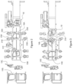
- Figures 2 and 3 schematically illustrate different steps of an example of laser cutting method in the system of figure 1 ;
- component 10C has been picked up from second laser cutting station 400 and is undergoing a visual inspection.
- robot 310 After removing component 10C from the second laser cutting station 400, robot 310 has position component 10B in the second laser cutting station.
- laser cutting actions are being finished on component 10A in the first laser cutting station.
- component 10A is pickup for trepanning and (in some cases) a visual inspection at station 300.
- Substantially simultaneously component 100 is positioned on first fixture 250 for laser cutting in the first laser cutting station 200.
- the speed of processing can be increased to keep pace with the speed of the hot stamping process.
- the cost can be much lower than when using traditional laser cells.
- the efficient arrangement on opposite sides of the fixtures and due to the fact that each of the robots only covers a relatively small area, the footprint of the operation can be kept small.
- left side components and right side components may be handled in parallel.
- one laser line according to the example of figure 1 may be configured to handle left side door panels and may run in parallel with another laser line configured for handling right side door panels.
- FIG 4a and figure 4b schematically illustrates an example of a process chain.
- the process chain may start with a steel coil 1000.
- Ultra high strength steel may be used for the manufacture of high strength components such as e.g. a B-pillar, a rocker or a unitary side panel.
- One example of a suitable steel is 22MnB5, such as Usibor TM .
- This steel may be provided with a protective coating, e.g. an aluminium-silicon coating or a zinc coating.
- Blanks of suitable dimensions may be cut 1010.
- a Tailor Welded Blank may be formed by edge-to-edge welding of several blanks 1030. If a steel with an aluminium silicon coating is used, this coating may be ablated 1020 at suitable locations to avoid the presence of aluminium in the weld area because this could negatively affect the strength.
- a TWB is formed for the manufacture of a unitary side panel.
- the tailor welded blank may be heated to above an austenization temperature, in particular to above Ac3.
- a hot stamping process 1050 is, according to the present invention, performed, optionally including tailored quenching/heating so as to obtain desirable microstructures in selected areas of the side panel. Additionally, localized heating of selected areas may take place to tailor the microstructure and mechanical properties as desired.
- multiple laser heads may substantially simultaneously perform trimming and cutting operations on the component.
- the number of robots with laser heads in e.g. of the stations may vary between one and six, and more particularly between two and four.
- a suitable number of robots may depend on the dimensions of the component to be laser cut and on the number of operations that need to be performed.
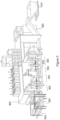
- FIG. 5 schematically illustrates an example of a laser cutting system, which substantially corresponds to the examples described hereinbefore.
- the several cutting stations may be enclosed in a housing 900.
- Auxiliary systems for temperature control, ventilation, electrical power etc. may be arranged on top of housing 900.
- a scrap removal system may be integrated in the laser cutting line as well.
- a scrap removal system 800 includes a scrap conveyor belt 820 which collects scrap from both the laser cutting stations 200 and 400 and moves in the opposite direction to the direction of the components. Scrap may be dropped in a scrap container 810.
- racks may be provided for stacking products in different piles 620 and 640. Multiple racks and piles might be used.
- a robot as used herein is meant to denote an automatically controlled, reprogrammable, multipurpose, manipulator programmable in three or more axes, for use in industrial automation applications.
- Multi-axis robot is preferably to be interpreted as a five or six axis robot.
- Each of the robots in the laser cutting line may be programmed to perform specific tasks. Coordination of the movements of the robots during their different tasks may be necessary so that accidents can be avoided, and the footprint of the laser cutting line may remain relatively small.
Landscapes
- Engineering & Computer Science (AREA)
- Physics & Mathematics (AREA)
- Optics & Photonics (AREA)
- Mechanical Engineering (AREA)
- Plasma & Fusion (AREA)
- Robotics (AREA)
- Laser Beam Processing (AREA)
Applications Claiming Priority (2)
| Application Number | Priority Date | Filing Date | Title |
|---|---|---|---|
| US201862671781P | 2018-05-15 | 2018-05-15 | |
| PCT/US2019/032277 WO2019222256A1 (en) | 2018-05-15 | 2019-05-14 | Laser cutting systems and methods |
Publications (2)
| Publication Number | Publication Date |
|---|---|
| EP3793764A1 EP3793764A1 (en) | 2021-03-24 |
| EP3793764B1 true EP3793764B1 (en) | 2024-11-27 |
Family
ID=66821375
Family Applications (1)
| Application Number | Title | Priority Date | Filing Date |
|---|---|---|---|
| EP19729949.8A Active EP3793764B1 (en) | 2018-05-15 | 2019-05-14 | Method for manufacturing a large structural component of a vehicle ; and method for manufacturing a unitary side panel for a door frame of a vehicle using such method |
Country Status (9)
| Country | Link |
|---|---|
| US (3) | US12275092B2 (cg-RX-API-DMAC10.html) |
| EP (1) | EP3793764B1 (cg-RX-API-DMAC10.html) |
| JP (1) | JP7496319B2 (cg-RX-API-DMAC10.html) |
| KR (1) | KR102745601B1 (cg-RX-API-DMAC10.html) |
| CN (1) | CN112654455A (cg-RX-API-DMAC10.html) |
| CA (1) | CA3099301A1 (cg-RX-API-DMAC10.html) |
| ES (1) | ES3004559T3 (cg-RX-API-DMAC10.html) |
| MX (1) | MX2020012250A (cg-RX-API-DMAC10.html) |
| WO (1) | WO2019222256A1 (cg-RX-API-DMAC10.html) |
Families Citing this family (6)
| Publication number | Priority date | Publication date | Assignee | Title |
|---|---|---|---|---|
| US12093013B2 (en) * | 2020-01-28 | 2024-09-17 | C. R. Onsrud, Inc. | Multi-axis computer numerical control machine tool with integrally-controlled saw and method |
| WO2022106875A1 (en) * | 2020-11-23 | 2022-05-27 | Arcelormittal | Process and equipment to laser cut very high strength metallic material |
| CN115533299A (zh) * | 2022-09-28 | 2022-12-30 | 上海美哲自动化装备有限公司 | 一种激光多头拼接视觉定位加工设备 |
| US20240139875A1 (en) * | 2022-10-26 | 2024-05-02 | GM Global Technology Operations LLC | Method of interface surface preparation for coated steel enabling laser weld or laser brazed assembly |
| CN116871717A (zh) * | 2023-07-31 | 2023-10-13 | 海斯坦普汽车组件(昆山)有限公司 | 一种全自动镭射切割检测设备及其使用方法 |
| CN118287818B (zh) * | 2024-05-08 | 2024-09-10 | 深圳清芬挺秀信息科技有限公司 | 带有散热功能的笔记本电脑外壳加工装置及其使用方法 |
Family Cites Families (35)
| Publication number | Priority date | Publication date | Assignee | Title |
|---|---|---|---|---|
| JPS63165086A (ja) * | 1986-12-26 | 1988-07-08 | Mitsubishi Electric Corp | レ−ザ応用加工組立装置 |
| RU2100168C1 (ru) | 1991-05-03 | 1997-12-27 | Кука Швайсанлаген + Роботер ГмбХ | Станция обработки заготовок преимущественно кузовов автомобилей на автоматической линии |
| US5380978A (en) * | 1991-07-12 | 1995-01-10 | Pryor; Timothy R. | Method and apparatus for assembly of car bodies and other 3-dimensional objects |
| US5223692A (en) * | 1991-09-23 | 1993-06-29 | General Electric Company | Method and apparatus for laser trepanning |
| CA2242139A1 (en) * | 1998-06-29 | 1999-12-29 | Automated Welding Systems Incorporated | Method of laser welding tailored blanks |
| JP3948327B2 (ja) | 2002-04-05 | 2007-07-25 | トヨタ自動車株式会社 | 搬送システム |
| EP1510643B1 (de) | 2003-09-01 | 2017-12-13 | Forster Profilsysteme AG | Profil und Verfahren zum Herstellen eines Profils |
| RU2360758C1 (ru) | 2007-11-01 | 2009-07-10 | Открытое акционерное общество "Магнитогорский металлургический комбинат" | Штамп для получения штамповкой полых изделий со сферическим дном из листового материала толщиной не более 4 мм, нагретого до необходимой температуры деформации |
| US8253064B2 (en) * | 2008-02-20 | 2012-08-28 | Automatic Feed Company | Progressive laser blanking device for high speed cutting |
| JP5266959B2 (ja) | 2008-08-22 | 2013-08-21 | マツダ株式会社 | 異種物品の溶接組立方法及びその装置 |
| JP5196170B2 (ja) | 2008-12-16 | 2013-05-15 | 株式会社Ihi | 溶接加工装置及び溶接加工方法 |
| CN102452002B (zh) * | 2010-10-22 | 2013-07-17 | 宝山钢铁股份有限公司 | 一种汽车板落料方法及系统 |
| RU2500514C2 (ru) | 2011-06-06 | 2013-12-10 | Открытое акционерное общество "АВТОВАЗ" | Способ изготовления листовой сварной заготовки для штамповки деталей автомобиля |
| RU2470769C1 (ru) | 2011-06-08 | 2012-12-27 | Открытое Акционерное Общество "Корпорация Всмпо-Ависма" | Способ вырезки контура металлических изделий |
| WO2013012006A1 (ja) | 2011-07-21 | 2013-01-24 | 株式会社神戸製鋼所 | 熱間プレス成形鋼部材の製造方法 |
| PL2554459T3 (pl) | 2011-08-01 | 2017-07-31 | Comau Spa | System montażu części składowej na konstrukcji nadwozia pojazdu samochodowego |
| KR101313338B1 (ko) * | 2011-12-08 | 2013-09-30 | 에스아이에스 주식회사 | 레이저 커팅 자동화 시스템 |
| RU133241U1 (ru) | 2013-01-29 | 2013-10-10 | Общество с ограниченной ответственностью Научно-производственная фирма "МКТ-АСДМ" | Сварной корпус задвижки |
| CN103600234A (zh) * | 2013-04-28 | 2014-02-26 | 宝山钢铁股份有限公司 | 一种钢板组合剪切方法与系统 |
| CN103624487A (zh) * | 2013-04-28 | 2014-03-12 | 宝山钢铁股份有限公司 | 一种开卷落料成形方法 |
| CN103600173B (zh) * | 2013-04-28 | 2015-12-09 | 宝山钢铁股份有限公司 | 一种二工位快台切割的方法及其系统 |
| CN103600172B (zh) * | 2013-04-28 | 2017-02-08 | 宝山钢铁股份有限公司 | 一种开卷落料方法 |
| DE102013210878A1 (de) * | 2013-06-11 | 2014-12-11 | Schuler Automation Gmbh & Co. Kg | Verfahren und Vorrichtung zur Herstellung eines Blechformteils |
| MX362042B (es) * | 2013-11-12 | 2019-01-07 | Magna Int Inc | Sistema y método para recorte con rayo laser de alto rendimiento. |
| US10086471B2 (en) | 2014-03-31 | 2018-10-02 | Lincoln Global, Inc. | Laser enclosure with reciprocally movable shuttle structure, and method of using same |
| US10391597B2 (en) | 2014-03-31 | 2019-08-27 | Lincoln Global, Inc. | Laser workstation with endless loop conveyor and coordinated access doors |
| CN106536122B (zh) * | 2014-07-23 | 2019-12-31 | 松下知识产权经营株式会社 | 激光加工系统以及激光加工方法 |
| EP3067129A1 (en) * | 2015-03-09 | 2016-09-14 | Autotech Engineering, A.I.E. | Press systems and methods |
| KR101713728B1 (ko) * | 2015-07-31 | 2017-03-09 | 현대자동차 주식회사 | 루프 레이저 브레이징 시스템용 브레이징 어셈블리 |
| CN105081584B (zh) * | 2015-08-31 | 2017-08-25 | 宝山钢铁股份有限公司 | 一种同步通板动态跟随激光切割的方法及其系统 |
| DE102015115463A1 (de) * | 2015-09-14 | 2017-03-16 | Wilco Wilken Lasertechnik GmbH | Vorrichtung und Verfahren zur Bearbeitung von Werkstücken |
| JP6619817B2 (ja) | 2015-11-09 | 2019-12-11 | 株式会社Fuji | 作業実行装置 |
| DE102016112231A1 (de) * | 2016-07-05 | 2018-01-11 | Fraunhofer-Gesellschaft zur Förderung der angewandten Forschung e.V. | Verfahren zur Herstellung eines gehärteten Blechbauteils |
| CN107199410B (zh) * | 2017-07-25 | 2019-04-02 | 东莞市盛雄激光设备有限公司 | 一种激光切割设备及其切割方法 |
| CN207267117U (zh) * | 2017-09-14 | 2018-04-24 | 华工法利莱切焊系统工程有限公司 | 一种汽车车身在线激光切孔装置 |
-
2019
- 2019-05-14 US US17/052,793 patent/US12275092B2/en active Active
- 2019-05-14 WO PCT/US2019/032277 patent/WO2019222256A1/en not_active Ceased
- 2019-05-14 MX MX2020012250A patent/MX2020012250A/es unknown
- 2019-05-14 CN CN201980032237.9A patent/CN112654455A/zh active Pending
- 2019-05-14 CA CA3099301A patent/CA3099301A1/en active Pending
- 2019-05-14 ES ES19729949T patent/ES3004559T3/es active Active
- 2019-05-14 EP EP19729949.8A patent/EP3793764B1/en active Active
- 2019-05-14 KR KR1020207035816A patent/KR102745601B1/ko active Active
- 2019-05-14 JP JP2020564240A patent/JP7496319B2/ja active Active
-
2025
- 2025-03-13 US US19/079,346 patent/US20250205828A1/en active Pending
- 2025-03-13 US US19/079,352 patent/US20250205829A1/en active Pending
Also Published As
| Publication number | Publication date |
|---|---|
| BR112020023114A2 (pt) | 2021-02-02 |
| EP3793764A1 (en) | 2021-03-24 |
| KR102745601B1 (ko) | 2024-12-20 |
| US12275092B2 (en) | 2025-04-15 |
| WO2019222256A1 (en) | 2019-11-21 |
| CA3099301A1 (en) | 2019-11-21 |
| US20210362278A1 (en) | 2021-11-25 |
| CN112654455A (zh) | 2021-04-13 |
| MX2020012250A (es) | 2021-04-28 |
| KR20210020023A (ko) | 2021-02-23 |
| JP7496319B2 (ja) | 2024-06-06 |
| US20250205828A1 (en) | 2025-06-26 |
| US20250205829A1 (en) | 2025-06-26 |
| ES3004559T3 (en) | 2025-03-12 |
| JP2021523020A (ja) | 2021-09-02 |
Similar Documents
| Publication | Publication Date | Title |
|---|---|---|
| US20250205828A1 (en) | Laser cutting systems and methods | |
| US20240425119A1 (en) | Body side structural frame of a vehicle | |
| US9802664B2 (en) | High density welding | |
| US8141230B2 (en) | Press-hardened component and process for producing a press-hardened component | |
| CN107107162A (zh) | 连续冲压线组件 | |
| EP3497254B1 (en) | Centering and selective heating of blanks | |
| JP2021523020A5 (cg-RX-API-DMAC10.html) | ||
| US20190352734A1 (en) | Method for Producing a Sheet Metal Component | |
| CN115961212A (zh) | 具有拼接的机械与腐蚀性质的组件 | |
| US20030046814A1 (en) | Method of making a sheet metal article with zones of different thickness | |
| US11821053B2 (en) | System for conditioning material using a laser and method thereof | |
| RU2804235C2 (ru) | Системы и способы лазерной резки | |
| BR112020023114B1 (pt) | Método para cortar um componente em um sistema de corte a laser,método para fabricar um painel lateral unitário e sistema de corte a laser | |
| RU2855251C2 (ru) | Задняя конструкция для механического транспортного средства | |
| CN218983584U (zh) | 一种敞车下侧门的修边系统 | |
| WO2025021939A1 (en) | Method for heating a blank and heating system | |
| WO2022215425A1 (ja) | プレス成形品の製造方法 | |
| Spoettl | High performance laser welding systems for the production of innovative laser welded automotive components | |
| KR20160127874A (ko) | 고강성 패널을 핫 스탬핑한 부분품의 연화 처리 장치 |
Legal Events
| Date | Code | Title | Description |
|---|---|---|---|
| STAA | Information on the status of an ep patent application or granted ep patent |
Free format text: STATUS: UNKNOWN |
|
| STAA | Information on the status of an ep patent application or granted ep patent |
Free format text: STATUS: THE INTERNATIONAL PUBLICATION HAS BEEN MADE |
|
| PUAI | Public reference made under article 153(3) epc to a published international application that has entered the european phase |
Free format text: ORIGINAL CODE: 0009012 |
|
| STAA | Information on the status of an ep patent application or granted ep patent |
Free format text: STATUS: REQUEST FOR EXAMINATION WAS MADE |
|
| 17P | Request for examination filed |
Effective date: 20201215 |
|
| AK | Designated contracting states |
Kind code of ref document: A1 Designated state(s): AL AT BE BG CH CY CZ DE DK EE ES FI FR GB GR HR HU IE IS IT LI LT LU LV MC MK MT NL NO PL PT RO RS SE SI SK SM TR |
|
| AX | Request for extension of the european patent |
Extension state: BA ME |
|
| DAV | Request for validation of the european patent (deleted) | ||
| DAX | Request for extension of the european patent (deleted) | ||
| P01 | Opt-out of the competence of the unified patent court (upc) registered |
Effective date: 20230530 |
|
| STAA | Information on the status of an ep patent application or granted ep patent |
Free format text: STATUS: EXAMINATION IS IN PROGRESS |
|
| 17Q | First examination report despatched |
Effective date: 20230926 |
|
| GRAP | Despatch of communication of intention to grant a patent |
Free format text: ORIGINAL CODE: EPIDOSNIGR1 |
|
| STAA | Information on the status of an ep patent application or granted ep patent |
Free format text: STATUS: GRANT OF PATENT IS INTENDED |
|
| INTG | Intention to grant announced |
Effective date: 20240517 |
|
| RIN1 | Information on inventor provided before grant (corrected) |
Inventor name: TROJANOWSKI, JAMES JOSEPH |
|
| GRAJ | Information related to disapproval of communication of intention to grant by the applicant or resumption of examination proceedings by the epo deleted |
Free format text: ORIGINAL CODE: EPIDOSDIGR1 |
|
| STAA | Information on the status of an ep patent application or granted ep patent |
Free format text: STATUS: EXAMINATION IS IN PROGRESS |
|
| GRAP | Despatch of communication of intention to grant a patent |
Free format text: ORIGINAL CODE: EPIDOSNIGR1 |
|
| STAA | Information on the status of an ep patent application or granted ep patent |
Free format text: STATUS: GRANT OF PATENT IS INTENDED |
|
| INTC | Intention to grant announced (deleted) | ||
| INTG | Intention to grant announced |
Effective date: 20240722 |
|
| GRAS | Grant fee paid |
Free format text: ORIGINAL CODE: EPIDOSNIGR3 |
|
| GRAA | (expected) grant |
Free format text: ORIGINAL CODE: 0009210 |
|
| STAA | Information on the status of an ep patent application or granted ep patent |
Free format text: STATUS: THE PATENT HAS BEEN GRANTED |
|
| AK | Designated contracting states |
Kind code of ref document: B1 Designated state(s): AL AT BE BG CH CY CZ DE DK EE ES FI FR GB GR HR HU IE IS IT LI LT LU LV MC MK MT NL NO PL PT RO RS SE SI SK SM TR |
|
| REG | Reference to a national code |
Ref country code: GB Ref legal event code: FG4D |
|
| REG | Reference to a national code |
Ref country code: CH Ref legal event code: EP |
|
| REG | Reference to a national code |
Ref country code: IE Ref legal event code: FG4D |
|
| REG | Reference to a national code |
Ref country code: DE Ref legal event code: R096 Ref document number: 602019062559 Country of ref document: DE |
|
| REG | Reference to a national code |
Ref country code: ES Ref legal event code: FG2A Ref document number: 3004559 Country of ref document: ES Kind code of ref document: T3 Effective date: 20250312 |
|
| REG | Reference to a national code |
Ref country code: LT Ref legal event code: MG9D |
|
| REG | Reference to a national code |
Ref country code: NL Ref legal event code: MP Effective date: 20241127 |
|
| PG25 | Lapsed in a contracting state [announced via postgrant information from national office to epo] |
Ref country code: PT Free format text: LAPSE BECAUSE OF FAILURE TO SUBMIT A TRANSLATION OF THE DESCRIPTION OR TO PAY THE FEE WITHIN THE PRESCRIBED TIME-LIMIT Effective date: 20250327 Ref country code: IS Free format text: LAPSE BECAUSE OF FAILURE TO SUBMIT A TRANSLATION OF THE DESCRIPTION OR TO PAY THE FEE WITHIN THE PRESCRIBED TIME-LIMIT Effective date: 20250327 Ref country code: HR Free format text: LAPSE BECAUSE OF FAILURE TO SUBMIT A TRANSLATION OF THE DESCRIPTION OR TO PAY THE FEE WITHIN THE PRESCRIBED TIME-LIMIT Effective date: 20241127 |
|
| PG25 | Lapsed in a contracting state [announced via postgrant information from national office to epo] |
Ref country code: FI Free format text: LAPSE BECAUSE OF FAILURE TO SUBMIT A TRANSLATION OF THE DESCRIPTION OR TO PAY THE FEE WITHIN THE PRESCRIBED TIME-LIMIT Effective date: 20241127 Ref country code: NL Free format text: LAPSE BECAUSE OF FAILURE TO SUBMIT A TRANSLATION OF THE DESCRIPTION OR TO PAY THE FEE WITHIN THE PRESCRIBED TIME-LIMIT Effective date: 20241127 |
|
| REG | Reference to a national code |
Ref country code: AT Ref legal event code: MK05 Ref document number: 1745271 Country of ref document: AT Kind code of ref document: T Effective date: 20241127 |
|
| PG25 | Lapsed in a contracting state [announced via postgrant information from national office to epo] |
Ref country code: BG Free format text: LAPSE BECAUSE OF FAILURE TO SUBMIT A TRANSLATION OF THE DESCRIPTION OR TO PAY THE FEE WITHIN THE PRESCRIBED TIME-LIMIT Effective date: 20241127 |
|
| PG25 | Lapsed in a contracting state [announced via postgrant information from national office to epo] |
Ref country code: NO Free format text: LAPSE BECAUSE OF FAILURE TO SUBMIT A TRANSLATION OF THE DESCRIPTION OR TO PAY THE FEE WITHIN THE PRESCRIBED TIME-LIMIT Effective date: 20250227 |
|
| PG25 | Lapsed in a contracting state [announced via postgrant information from national office to epo] |
Ref country code: LV Free format text: LAPSE BECAUSE OF FAILURE TO SUBMIT A TRANSLATION OF THE DESCRIPTION OR TO PAY THE FEE WITHIN THE PRESCRIBED TIME-LIMIT Effective date: 20241127 Ref country code: GR Free format text: LAPSE BECAUSE OF FAILURE TO SUBMIT A TRANSLATION OF THE DESCRIPTION OR TO PAY THE FEE WITHIN THE PRESCRIBED TIME-LIMIT Effective date: 20250228 Ref country code: AT Free format text: LAPSE BECAUSE OF FAILURE TO SUBMIT A TRANSLATION OF THE DESCRIPTION OR TO PAY THE FEE WITHIN THE PRESCRIBED TIME-LIMIT Effective date: 20241127 |
|
| PG25 | Lapsed in a contracting state [announced via postgrant information from national office to epo] |
Ref country code: PL Free format text: LAPSE BECAUSE OF FAILURE TO SUBMIT A TRANSLATION OF THE DESCRIPTION OR TO PAY THE FEE WITHIN THE PRESCRIBED TIME-LIMIT Effective date: 20241127 |
|
| PG25 | Lapsed in a contracting state [announced via postgrant information from national office to epo] |
Ref country code: RS Free format text: LAPSE BECAUSE OF FAILURE TO SUBMIT A TRANSLATION OF THE DESCRIPTION OR TO PAY THE FEE WITHIN THE PRESCRIBED TIME-LIMIT Effective date: 20250227 |
|
| PG25 | Lapsed in a contracting state [announced via postgrant information from national office to epo] |
Ref country code: SM Free format text: LAPSE BECAUSE OF FAILURE TO SUBMIT A TRANSLATION OF THE DESCRIPTION OR TO PAY THE FEE WITHIN THE PRESCRIBED TIME-LIMIT Effective date: 20241127 |
|
| PG25 | Lapsed in a contracting state [announced via postgrant information from national office to epo] |
Ref country code: DK Free format text: LAPSE BECAUSE OF FAILURE TO SUBMIT A TRANSLATION OF THE DESCRIPTION OR TO PAY THE FEE WITHIN THE PRESCRIBED TIME-LIMIT Effective date: 20241127 |
|
| PG25 | Lapsed in a contracting state [announced via postgrant information from national office to epo] |
Ref country code: EE Free format text: LAPSE BECAUSE OF FAILURE TO SUBMIT A TRANSLATION OF THE DESCRIPTION OR TO PAY THE FEE WITHIN THE PRESCRIBED TIME-LIMIT Effective date: 20241127 |
|
| PG25 | Lapsed in a contracting state [announced via postgrant information from national office to epo] |
Ref country code: RO Free format text: LAPSE BECAUSE OF FAILURE TO SUBMIT A TRANSLATION OF THE DESCRIPTION OR TO PAY THE FEE WITHIN THE PRESCRIBED TIME-LIMIT Effective date: 20241127 |
|
| PG25 | Lapsed in a contracting state [announced via postgrant information from national office to epo] |
Ref country code: SK Free format text: LAPSE BECAUSE OF FAILURE TO SUBMIT A TRANSLATION OF THE DESCRIPTION OR TO PAY THE FEE WITHIN THE PRESCRIBED TIME-LIMIT Effective date: 20241127 |
|
| PG25 | Lapsed in a contracting state [announced via postgrant information from national office to epo] |
Ref country code: CZ Free format text: LAPSE BECAUSE OF FAILURE TO SUBMIT A TRANSLATION OF THE DESCRIPTION OR TO PAY THE FEE WITHIN THE PRESCRIBED TIME-LIMIT Effective date: 20241127 |
|
| PG25 | Lapsed in a contracting state [announced via postgrant information from national office to epo] |
Ref country code: IT Free format text: LAPSE BECAUSE OF FAILURE TO SUBMIT A TRANSLATION OF THE DESCRIPTION OR TO PAY THE FEE WITHIN THE PRESCRIBED TIME-LIMIT Effective date: 20241127 |
|
| REG | Reference to a national code |
Ref country code: DE Ref legal event code: R097 Ref document number: 602019062559 Country of ref document: DE |
|
| PG25 | Lapsed in a contracting state [announced via postgrant information from national office to epo] |
Ref country code: SE Free format text: LAPSE BECAUSE OF FAILURE TO SUBMIT A TRANSLATION OF THE DESCRIPTION OR TO PAY THE FEE WITHIN THE PRESCRIBED TIME-LIMIT Effective date: 20241127 |
|
| PLBE | No opposition filed within time limit |
Free format text: ORIGINAL CODE: 0009261 |
|
| STAA | Information on the status of an ep patent application or granted ep patent |
Free format text: STATUS: NO OPPOSITION FILED WITHIN TIME LIMIT |
|
| REG | Reference to a national code |
Ref country code: CH Ref legal event code: L10 Free format text: ST27 STATUS EVENT CODE: U-0-0-L10-L00 (AS PROVIDED BY THE NATIONAL OFFICE) Effective date: 20251008 |
|
| 26N | No opposition filed |
Effective date: 20250828 |
|
| REG | Reference to a national code |
Ref country code: CH Ref legal event code: H13 Free format text: ST27 STATUS EVENT CODE: U-0-0-H10-H13 (AS PROVIDED BY THE NATIONAL OFFICE) Effective date: 20251223 |
|
| PG25 | Lapsed in a contracting state [announced via postgrant information from national office to epo] |
Ref country code: LU Free format text: LAPSE BECAUSE OF NON-PAYMENT OF DUE FEES Effective date: 20250514 |
|
| PG25 | Lapsed in a contracting state [announced via postgrant information from national office to epo] |
Ref country code: CH Free format text: LAPSE BECAUSE OF NON-PAYMENT OF DUE FEES Effective date: 20250531 |
|
| GBPC | Gb: european patent ceased through non-payment of renewal fee |
Effective date: 20250514 |
|
| REG | Reference to a national code |
Ref country code: BE Ref legal event code: MM Effective date: 20250531 |
|
| PG25 | Lapsed in a contracting state [announced via postgrant information from national office to epo] |
Ref country code: MC Free format text: LAPSE BECAUSE OF FAILURE TO SUBMIT A TRANSLATION OF THE DESCRIPTION OR TO PAY THE FEE WITHIN THE PRESCRIBED TIME-LIMIT Effective date: 20241127 |
|
| PG25 | Lapsed in a contracting state [announced via postgrant information from national office to epo] |
Ref country code: GB Free format text: LAPSE BECAUSE OF NON-PAYMENT OF DUE FEES Effective date: 20250514 |
|
| PG25 | Lapsed in a contracting state [announced via postgrant information from national office to epo] |
Ref country code: IE Free format text: LAPSE BECAUSE OF NON-PAYMENT OF DUE FEES Effective date: 20250514 |
|
| PG25 | Lapsed in a contracting state [announced via postgrant information from national office to epo] |
Ref country code: BE Free format text: LAPSE BECAUSE OF NON-PAYMENT OF DUE FEES Effective date: 20250531 |
|
| PG25 | Lapsed in a contracting state [announced via postgrant information from national office to epo] |
Ref country code: FR Free format text: LAPSE BECAUSE OF NON-PAYMENT OF DUE FEES Effective date: 20250531 |
|
| PG25 | Lapsed in a contracting state [announced via postgrant information from national office to epo] |
Ref country code: LT Free format text: LAPSE BECAUSE OF FAILURE TO SUBMIT A TRANSLATION OF THE DESCRIPTION OR TO PAY THE FEE WITHIN THE PRESCRIBED TIME-LIMIT Effective date: 20241127 |
|
| PGFP | Annual fee paid to national office [announced via postgrant information from national office to epo] |
Ref country code: ES Payment date: 20260601 Year of fee payment: 8 |
|
| PGFP | Annual fee paid to national office [announced via postgrant information from national office to epo] |
Ref country code: DE Payment date: 20260528 Year of fee payment: 8 |
|
| PGFP | Annual fee paid to national office [announced via postgrant information from national office to epo] |
Ref country code: TR Payment date: 20260427 Year of fee payment: 8 |
|
| PG25 | Lapsed in a contracting state [announced via postgrant information from national office to epo] |
Ref country code: CY Free format text: LAPSE BECAUSE OF FAILURE TO SUBMIT A TRANSLATION OF THE DESCRIPTION OR TO PAY THE FEE WITHIN THE PRESCRIBED TIME-LIMIT Effective date: 20241127 |