EP3792667A1 - Container inspection system, port facility and container inspection method - Google Patents
Container inspection system, port facility and container inspection method Download PDFInfo
- Publication number
- EP3792667A1 EP3792667A1 EP19799514.5A EP19799514A EP3792667A1 EP 3792667 A1 EP3792667 A1 EP 3792667A1 EP 19799514 A EP19799514 A EP 19799514A EP 3792667 A1 EP3792667 A1 EP 3792667A1
- Authority
- EP
- European Patent Office
- Prior art keywords
- container
- inspection
- station
- stations
- inspection device
- Prior art date
- Legal status (The legal status is an assumption and is not a legal conclusion. Google has not performed a legal analysis and makes no representation as to the accuracy of the status listed.)
- Granted
Links
Images


Classifications
-
- G—PHYSICS
- G01—MEASURING; TESTING
- G01V—GEOPHYSICS; GRAVITATIONAL MEASUREMENTS; DETECTING MASSES OR OBJECTS; TAGS
- G01V5/00—Prospecting or detecting by the use of ionising radiation, e.g. of natural or induced radioactivity
- G01V5/20—Detecting prohibited goods, e.g. weapons, explosives, hazardous substances, contraband or smuggled objects
- G01V5/22—Active interrogation, i.e. by irradiating objects or goods using external radiation sources, e.g. using gamma rays or cosmic rays
Definitions
- the present disclosure relates to the field of scanning inspection technology, in particular to a container inspection system, a port facility, and a container inspection method.
- scanning inspection is usually performed on containers after cargo is unloaded.
- the container is transported by an AGV transfer trolley (or container transport truck) in a yard to a designated location to perform scanning inspection on the container.
- AGV transfer trolley or container transport truck
- This requires a special area for scanning inspection at the port. Not only is a large space occupied, but also long time is consumed, and the circulation efficiency of the container at the port is low. Besides, dangerous prohibited articles may enter the yard, causing potential safety hazards.
- Embodiments of the present disclosure propose a container inspection system, a port facility, and a container inspection method, to improve the efficiency of scanning inspection as much as possible.
- the present disclosure provides a container inspection system, including:
- the container inspection system further includes a switching mechanism, which is configured to switch the inspection device among the plurality of stations.
- the switching mechanism includes: a rotary switching mechanism, which is connected with the inspection device, for rotating at least part of the inspection device, so that after finishing scanning inspection on the container on one of the plurality of stations, the inspection device is configured to perform scanning inspection on the container on another of the plurality of stations.
- the plurality of stations include a first station and a second station, wherein the first station is arranged on a side of a long edge of the second station, and a long edge of the first station and the long edge of the second station are parallel to each other; and the switching mechanism is configured to rotate at least part of the inspection device 180 degrees.
- the inspection device includes a cabin, a ray source and an L-shaped arm installed with a detector, the ray source being disposed in the cabin and rotatable relative to the cabin, and the L-shaped arm being mounted on the cabin and rotatable relative to the cabin.
- the plurality of stations include a first station and a second station, wherein the first station is arranged on a side of a short edge of the second station, and a short edge of the first station and the short edge of the second station are parallel to each other; and the switching mechanism includes: a linear switching mechanism, which is connected with the inspection device, for enabling the inspection device to continue to move along a long edge of the second station after finishing scanning inspection on the container located on the first station, to perform scanning inspection on the container located on the second station.
- the first hoisting component is further configured to hoist the container on which scanning inspection is completed from the station where the container is located and transport the container to a container transport equipment.
- the quay crane further includes a second hoisting component for hoisting the container on which scanning inspection is completed from the station where the container is located and transporting the container to a container transport equipment.
- the container inspection system further includes a guide mechanism disposed on the inspection platform, for guiding the container to fall in place on at least one of the plurality of stations.
- the guide mechanism includes: a plurality of guide pillars with conic tops and being arranged along edges of at least one of the plurality of stations.
- the guide mechanism is liftable.
- the inspection device includes a cabin, a ray source and an L-shaped arm installed with a detector, the ray source being disposed in the cabin, and the L-shaped arm being mounted on the cabin; and the guide mechanism includes:
- a container inspection system includes:
- the container inspection system further includes: a switching device, in drive connection with the inspection device and configured to drive the inspection device to rotate or perform linear motion relative to the inspection platform, so that the inspection device switches from one to another of the plurality of stations.
- a switching device in drive connection with the inspection device and configured to drive the inspection device to rotate or perform linear motion relative to the inspection platform, so that the inspection device switches from one to another of the plurality of stations.
- the plurality of stations include a first station and a second station, the first station being arranged on a side of the second station along a first direction, the first direction being a length direction of the container; and the switching device is configured to drive the inspection device to rotate 180 degrees relative to the inspection platform, to achieve switching of the inspection device between the first station and the second station.
- the inspection device includes:
- the plurality of stations include a first station and a second station, the first station being arranged on a side of the second station along a second direction, the second direction being a width direction of the container; and the switching device is configured to drive the inspection device to perform linear motion along a first direction, to achieve switching of the inspection device between the first station and the second station, the first direction being a length direction of the container.
- the guide mechanism is liftable relative to the inspection platform.
- the present disclosure further provides a port facility, which includes the above-mentioned container inspection system.
- the present disclosure further provides a container inspection method, including:
- the container inspection method further includes: hoisting the container on which scanning inspection is completed from the station where the container is located and transporting the container to a container transport equipment.
- a container inspection method includes:
- driving an inspection device disposed on the inspection platform to switch among the plurality of stations includes: driving the inspection device disposed on the inspection platform to rotate or perform linear motion relative to the inspection platform, so that the inspection device switches from one to another of the plurality of stations.
- the inspection device in the embodiment of the container inspection system of the present disclosure may switch among the plurality of stations and move relative to the container on each station, respectively, so as to perform scanning inspection on the container on each station, respectively, so that the inspection position of the container inspection system may be more flexible.
- the inspection device is not limited to scanning inspection at a specific station. After finishing scanning inspection on the container on one of the stations, the inspection device may turn to another station and perform scanning inspection on the container on the another station, thereby improving the efficiency of scanning inspection.
- the port facility and the container inspection method provided by the present disclosure also correspondingly have the above-mentioned beneficial technical effects.
- orientation or position relations denoted by the terms “center”, “transverse”, “longitudinal”, “front”, “rear”, “left”, “right”, “upper”, “lower”, “vertical”, “horizontal”, “top”, “bottom”, “inner”, “outer” and the like are orientation or position relations illustrated based on the drawings, are merely for the convenience of describing the present disclosure and simplifying description, instead of indicating or implying the denoted devices or elements must have specific orientations or be constructed and operated in specific orientations, and thus the terms cannot be understood as limiting the protection scope of the present disclosure.
- the container inspection system includes a quay crane 100 and an inspection device 200, wherein the quay crane 100 includes a first hoisting component 101 and an inspection platform 103 provided with a plurality of stations, the first hoisting component 101 being configured to hoist a container 300 and transport the container 300 to at least one of the plurality of stations; and the inspection device 200 is disposed on the inspection platform 103 and configured to move relative to the container 300 on each of the plurality of stations, to perform scanning inspection on the container 300 on each of the plurality of stations, respectively.
- the inspection device 200 is disposed on the inspection platform 103, and thus may move with the movement of the quay crane 100; at the same time, the inspection device 200 may also move on the inspection platform 103 relative to the container 300 on the station to perform scanning inspection on the container 300.
- the inspection device 200 may move relative to the container 300 on each station, respectively, to perform scanning inspection on the container 300 on each station, so that the inspection position of the container inspection system may be more flexible.
- the inspection device 200 is not limited to scanning inspection at a specific station. After finishing scanning inspection on the container 300 on one of the stations, the inspection device 200 may turn to another station and perform scanning inspection on the container 300 on the another station, thus being beneficial to improving the efficiency of scanning inspection.
- a floor area occupied by the inspection device 200 may be reduced, and there is no need to reserve a special inspection location for the inspection device 200 in an area outside the quay crane, so that the overall layout of the port is more reasonable; and arranging the inspection device 200 on the inspection platform 103 of the quay crane 100 may also achieve the scanning inspection during the process of unloading the container 300 from a ship or during the process of loading the container 300 from the ground to a ship, to avoid in-yard inspection, and the process of transferring the container 300 to an AGV trolley and transporting by the AGV trolley the container 300 to an inspection location is omitted, thereby greatly reducing loading, unloading and scanning inspection time of the container 300, shortening the total circulation time of the container 300 at the port, and improving the circulation efficiency; this may also prevent dangerous prohibited articles from entering a yard, and improve the safety.
- the container inspection system further includes a drive mechanism, which is configured to drive the inspection device 200 to move relative to the container 300.
- guide rails are provided on two sides of each station, and the inspection device 200 moves along the guide rails to ensure the accuracy of the movement route of the inspection device 200 and improve the accuracy of scanning inspection.
- the container inspection system further includes a switching mechanism, which is configured to switch the inspection device 200 among the plurality of stations.
- the inspection device 200 may quickly switch among the plurality of stations, and from an attitude capable of scanning inspecting on the container 300 on one station to an attitude capable of scanning inspection on the container 300 on another station, thereby improving the degree of automation of the container inspection system; moreover, after finishing scanning inspection on the container 300 on one station, the inspection device 200 may quickly switch into a state of scanning inspection on the container 300 on another station, instead of that after scanning inspection on the container on an inspection station is finished, it also needs to transfer the container from the inspection station to a temporary storage station, and wait for the next container to arrive at the inspection station so as to start scanning inspection on the next container like in the related art, thus greatly shortening the waiting time for the inspection device 200 to perform scanning inspection on the next container, and improving the scanning inspection efficiency.
- the switching mechanism includes a rotary switching mechanism, which is connected with the inspection device 200, for rotating at least part of the inspection device 200, so that after finishing scanning inspection on the container 300 on one of the plurality of stations, the inspection device 200 can perform scanning inspection on the container 300 on another of the plurality of stations.
- the rotary switching mechanism is simple in movement form and flexible in switching, which is beneficial to shortening the switching time and improving the efficiency of scanning inspection.
- the switch mechanism being configured to be rotary also enables the arrangement of the plurality of stations to be more convenient.
- the plurality of stations include a first station 104 and a second station 105, wherein the first station 104 is arranged on a side of a long edge of the second station 105, and a long edge of the first station 104 and the long edge of the second station 105 are parallel to each other; and the switching mechanism is configured to rotate at least part of the inspection device 200 by 180 degrees. As shown in Figs. 5 and 6 , after finishing scanning inspection on the container 300 on the first station 104, the inspection device 200 rotates 180 degrees and thereby can perform scanning inspection on the container 300 on the second station 105.
- the area ranges of the first station 104 and the second station 105 are roughly similar to the shape of the container 300.
- the container 300 is in the shape of a cuboid.
- the long edge of the first station 104 and the long edge of the second station 105 described above are parallel to a length direction of the container 300 (as a first direction).
- the plurality of stations may also include three stations, which are evenly arranged around the circumference.
- the inspection device 200 may rotate 120 degrees to switch to scanning inspection on the container 300 on another station adjacent thereto.
- the inspection device 200 may also switch to scanning inspection on another container 300 by rotating an appropriate angle, which is not detailed here.
- the inspection device 200 optionally, but not limited to, moves in the length direction of the container 300.
- the inspection device 200 includes a cabin 201, a ray source 202 and an L-shaped arm installed with a detector, the ray source 202 being disposed in the cabin 201 and rotatable relative to the inspection platform 103, and the L-shaped arm being mounted on the cabin 201 and rotatable relative to the inspection platform 103.
- the inspection device 200 includes a rotation drive mechanism, which is configured to drive the ray source 202 and/or the L-shaped arm to rotate relative to the cabin 201.
- the top of the cabin 201 is provided with a slewing bearing 205, wherein an outer ring of the slewing bearing 205 is connected with the cabin 201, an inner ring of the slewing bearing 205 is connected with a horizontally arranged horizonal arm 203 of the L-shaped arm, and a vertically arranged vertical arm 204 is connected with the horizonal arm 203.
- Rotation of the inner ring relative to the outer ring of the slewing bearing 205 may cause the L-shaped arm to rotate relative to the cabin 201, to achieve switching of the inspection device 200 between different stations.
- the slewing bearing 205 may be driven into rotation by a power device such as a hydraulic motor, a friction wheels, or a brake.
- a power device such as a hydraulic motor, a friction wheels, or a brake.
- a rotation mechanism may be provided between the ray source 202 and the cabin 201, so that the ray source 202 can also rotate relative to the cabin 201. This will not be detailed here.
- the switching of the inspection device 200 between different stations may also be achieved in such a manner that the cabin 201 rotates relative to the inspection platform 103 to cause the ray source 202 and the L-shaped arm to rotate.
- the manner that the cabin 201 is fixed relative to the inspection platform 103 and the ray source 202 and the L-shaped arm rotate relative to the inspection platform 103 is not limited by the shape of the cabin 201, and does not involve an increase in the spacing width between two stations due to a reserved space for rotation of the cabin 201.
- the plurality of stations include a first station 104 and a second station 105, wherein the first station 104 is arranged on a side of a short edge of the second station 105, and a short edge of the first station 104 and the short edge of the second station 105 are parallel to each other; and the switching mechanism includes a linear switching mechanism, which is connected with the inspection device 200, for enabling the inspection device 200 to continue to move along a long edge of the second station 105 after finishing scanning inspection on the container 300 located on the first station 104, to perform scanning inspection on the container 300 located on the second station 105.
- the area ranges of the first station 104 and the second station 105 are roughly similar to the shape of the container 300.
- the container 300 is in the shape of a cuboid.
- the short edge of the first station 104 and the short edge of the second station 105 described above are parallel to a width direction of the container 300 (as a second direction).
- the linear switching mechanism may be understood as a mechanism that causes the inspection device 200 to move linearly.
- the linear switching mechanism may cause the inspection device 200 to move along the length direction of the container 300 on the first station 104, and after finishing scanning inspection on the container 300, continues to move along the length direction of the container 300 on the second station 105 to perform scanning inspection on the container 300 on the second station 105.
- the linear switching mechanism and the drive mechanism that drives the inspection device 200 to move may be a same mechanism.
- the drive mechanism in the embodiment drives the inspection device 200 to move along a same direction for longer time.
- the first hoisting component 101 is further configured to hoist the container 300 on which scanning inspection is completed from the station where the container is located and transport the container 300 to a container transport equipment, so as to transport the container 300 to a target location by the container transport equipment.
- the target location in the case where the container is unloaded from a cargo carrying equipment such as a ship, the target location may be a warehouse for storing containers on the ground of a yard of the port, or may also be a freight truck loaded with containers, etc.; and in the case where the container is loaded to a cargo carrying equipment such as a ship, the target location may be a storage bin for storing containers on the cargo carrying equipment such as a ship.
- the above-mentioned container transport equipment may be an AGV trolley, a container transport truck or the like.
- the above-mentioned container moving equipment may be an equipment, disposed on the cargo carrying equipment such as a ship, for placing containers to corresponding storage bins.
- the quay crane 100 further includes a second hoisting component 102 for hoisting the container 300 on which scanning inspection is completed from the station where the container is located and transporting the container 300 to a container transport equipment. That is, the first hoisting component 101 is configured to hoist the container 300 and transport the container 300 to at least one of the plurality of stations, and the second hoisting component 102 is configured to hoist the container 300 on which scanning inspection is completed from the station where the container is located and transport the container 300 to a container transport equipment.
- the first hoisting component 101 is configured to hoist the container 300 and transport the container 300 to at least one of the plurality of stations
- the second hoisting component 102 is configured to hoist the container 300 on which scanning inspection is completed from the station where the container is located and transport the container 300 to a container transport equipment.
- the set height of the second hoisting component 102 is lower than that of the first hoisting component 101 to avoid interference between the two hoisting components on travel routes, and also shorten the path for hoisting and moving away the container 300 and improve the circulation efficiency.
- the container inspection system further includes a guide mechanism disposed on the inspection platform 103, for guiding the container 300 to fall in place on at least one of the plurality of stations.
- the container 300 may fall accurately; it may also limit the container 300 to prevent the container 300 from deviating from the station disposed on the inspection platform 103, and ensure the container 300 may be accurately hoisted every time after the first hoisting component 101 or the second hoisting component 102 falls, thereby reducing the alignment time and improving the circulation efficiency.
- the guide mechanism includes a plurality of guide pillars having conic tops and arranged along edges of at least one of the plurality of stations, such that the container 300 may be guided and positioned by the guide pillars.
- the tops of the guide pillars are cone-shaped, so that the container 300 may be better guided to fall quickly and accurately.
- the guide mechanism is liftable relative to the inspection platform 103.
- the guide mechanism may be raised to guide the container 300; after the container 300 falls in place, the and guide mechanism may be dropped to prevent the guide mechanism from influencing the movement of the inspection device 200; in addition, when the inspection device 200 switches between different stations, the and guide mechanism is dropped so that the guide mechanism may be prevented from interfering with the switching of the inspection device 200.
- the inspection device 200 includes a cabin 201, a ray source 202 and an L-shaped arm installed with a detector, the ray source 202 being disposed in the cabin 201, and the L-shaped arm being mounted on the cabin 201; and the guide mechanism includes a plurality of first guide pillars 106 and a plurality of second guide pillars 107, wherein the first guide pillars 106 are disposed on a side of the plurality of stations close to the cabin 201, the plurality of first guide pillars 106 being non-liftable; and the second guide pillars 107 are disposed on a side of the plurality of stations away from the cabin 201, the plurality of second guide pillars 107 being liftable.
- This arrangement may simplify the control as much as possible and improve the operation efficiency while ensuring the normal movement and switching of the inspection device 200.
- the present disclosure further proposes a port facility, which includes the above-mentioned container inspection system.
- a port facility which includes the above-mentioned container inspection system.
- the present disclosure further proposes a container inspection method, the inspection method including:
- the container inspection method further includes: hoisting the container 300 on which scanning inspection is completed from the station where the container is located and transporting the container 300 to a container transport equipment.
- the method may further include: detecting whether the container 300 is in place; if yes, executing the step of driving the inspection device 200 to move; and if not, performing detection again until detecting that the container 300 is in place.
- the container inspection system includes a quay crane 100, and the quay crane 100 is provided with a first hoisting component 101.
- the first hoisting component 101 hoists the container 300 from a container transport equipment such as a ship and places the container 300 onto an inspection platform 103 disposed on the quay crane 100.
- the inspection platform 103 is provided with a first station 104 and a second station 105, the sizes of the first station 104 and the second station 105 being substantially same as the size of the container 300.
- the container 300 is in the shape of a cuboid.
- the first station 104 is arranged on a side of a long edge of the second station 105, and a long edge of the first station 104 and the long edge of the second station 105 are parallel to each other; and a line connecting the center of the first station 104 and the center of the second station 105, and the long edge of the first station 104 are parallel to each other.
- the inspection device 200 includes a cabin 201, and a ray source 202 disposed in the cabin 201.
- the top of the cabin 201 is provided with a slewing bearing 205, wherein an outer ring of the slewing bearing 205 is connected with the cabin 201, and an inner ring of the slewing bearing 205 is connected with an L-shaped arm.
- the L-shaped arm is installed with a detector, and the L-shaped arm includes a horizontally arranged horizonal arm 203 and a vertically arranged vertical arm 204.
- the cabin 201 is arranged between the first station 104 and the second station 105, and the L-shaped arm spans across the stations on the inspection platform 103.
- a plurality of first guide pillars 106 are disposed on a side of the first station 104 away from the cabin 201 and on a side of the second station 105 away from the cabin 201, with a distance formed between every two adjacent first guide pillars 106, the first guide pillars 106 being liftable; and a plurality of second guide pillars 107 are disposed on a side of the first station 104 close to the cabin 201 and on a side of the second station 105 close to the cabin 201, with a distance formed between every two adjacent second guide pillars 107, the second guide pillars 107 being non-liftable.
- the quay crane 100 is further provided with a second hoisting component 102.
- the container 300 on which scanning inspection is completed on the first station 104 or the second station 105 may be hoisted and transported to a container transport equipment such as an AGV trolley or a container transport truck at a port, and the container is transported to a target location by the container transport equipment.
- a container 300 is hoisted and transported by the first hoisting component 101 from a ship to the first station 104, and after the container 300 is detected to fall in place, the inspection device 200 is started and moves relative to the first station 104, to perform scanning inspection on the container 300 on the first station 104; during the scanning inspection on the container 300 on the first station 104, the first hoisting component 101 may hoist a second container 300 from the ship and transport the second container 300 to the second station 105, and the inspection device 200 rotates 180 degrees after finishing scanning inspection on the container 300 on the first station 104, and the vertical arm 204 rotates from the left side of the first station 104 to the right side of the second station 105, and the inspection device 200 may return to an initial end and then move relative to the second station 105, and perform scanning inspection on the container 300 on the second station 105 during the movement, or the inspection device 200 may not return to the initial end first, but performs scanning inspection on the
- first station 104 and the second station 105 are both empty, it is also possible that a container 300 is hoisted and transported to the first station 104, and a second container 300 is hoisted and transported to the second station 105, by the first hoisting component 101, and then the inspection device 200 is started.
- the container 300 on which scanning inspection is completed on the first station 104 may be hoisted and transported by the first hoisting component 101 or the second hoisting component 102 to an AGV trolley (or container transport truck) on the ground of the port, and then a third container 300 is hoisted and transported by the first hoisting component 101 from a ship to the first station 104, so that after finishing scanning inspection on the container 300 on the second station 105, the inspection device 200 may continue, by switching, to perform scanning inspection on the third container 300 on the first station 104.
- the process proceeds in this way to accomplish continuous scanning inspection on multiple containers 300.
- the first guide pillars 106 on the left side of the first station 104 and on the right side of the second station 105 rise to guide the falling process of the container 300; after the container 300 falls in place, the first guide pillars 106 fall to prevent the first guide pillars 106 from influencing the movement of the inspection device 200; moreover, when the L-shaped arm of the inspection device 200 rotates, the first guide pillars 106 also need to be in a fallen state, to avoid collision with the first guide pillars 106 during rotation the L-shaped arm.
- the embodiments of the container inspection system, the port facility, and the container inspection method of the present disclosure have at least one or more of the following advantages:
Landscapes
- Physics & Mathematics (AREA)
- High Energy & Nuclear Physics (AREA)
- Life Sciences & Earth Sciences (AREA)
- General Life Sciences & Earth Sciences (AREA)
- General Physics & Mathematics (AREA)
- Geophysics (AREA)
- Analysing Materials By The Use Of Radiation (AREA)
- Warehouses Or Storage Devices (AREA)
- Control And Safety Of Cranes (AREA)
Abstract
Description
- The present application is based on and claims priority to Chinese patent application No.
201810426091.3, filed on May 7, 2018 - The present disclosure relates to the field of scanning inspection technology, in particular to a container inspection system, a port facility, and a container inspection method.
- With the development of the vessel industry, the workload of container loading and unloading operations is increasing. As large equipment for loading and unloading containers, quay cranes are increasingly used in various ports to achieve automated loading and unloading.
- To prevent prohibited cargo from entering the territory through ports and ensure the safety of cargo in circulation, scanning inspection is usually performed on containers after cargo is unloaded. At present, generally after a container is unloaded by a quay crane, the container is transported by an AGV transfer trolley (or container transport truck) in a yard to a designated location to perform scanning inspection on the container. This requires a special area for scanning inspection at the port. Not only is a large space occupied, but also long time is consumed, and the circulation efficiency of the container at the port is low. Besides, dangerous prohibited articles may enter the yard, causing potential safety hazards.
- In addition, due to limited space, there is usually only one station for scanning inspection on containers, which greatly limits the efficiency of scanning inspection, resulting in a large accumulation of containers.
- It should be noted that the information disclosed in the background section of the present disclosure is only intended to enhance understanding of the general background of the present disclosure, and should not be considered as an admission or any form of implication that the information constitutes related technology well known to those skilled in the art.
- Embodiments of the present disclosure propose a container inspection system, a port facility, and a container inspection method, to improve the efficiency of scanning inspection as much as possible.
- According to an aspect of the present disclosure, the present disclosure provides a container inspection system, including:
- a quay crane, which includes a first hoisting component and an inspection platform provided with a plurality of stations, the first hoisting component being configured to hoist a container and transport the container to at least one of the plurality of stations; and
- an inspection device, which is disposed on the inspection platform and configured to move relative to the container on each of the plurality of stations, to perform scanning inspection on the container on each of the plurality of stations, respectively.
- In some embodiments, the container inspection system further includes a switching mechanism, which is configured to switch the inspection device among the plurality of stations.
- In some embodiments, the switching mechanism includes:
a rotary switching mechanism, which is connected with the inspection device, for rotating at least part of the inspection device, so that after finishing scanning inspection on the container on one of the plurality of stations, the inspection device is configured to perform scanning inspection on the container on another of the plurality of stations. - In some embodiments, the plurality of stations include a first station and a second station, wherein the first station is arranged on a side of a long edge of the second station, and a long edge of the first station and the long edge of the second station are parallel to each other; and the switching mechanism is configured to rotate at least part of the inspection device 180 degrees.
- In some embodiments, the inspection device includes a cabin, a ray source and an L-shaped arm installed with a detector, the ray source being disposed in the cabin and rotatable relative to the cabin, and the L-shaped arm being mounted on the cabin and rotatable relative to the cabin.
- In some embodiments, the plurality of stations include a first station and a second station, wherein the first station is arranged on a side of a short edge of the second station, and a short edge of the first station and the short edge of the second station are parallel to each other; and the switching mechanism includes:
a linear switching mechanism, which is connected with the inspection device, for enabling the inspection device to continue to move along a long edge of the second station after finishing scanning inspection on the container located on the first station, to perform scanning inspection on the container located on the second station. - In some embodiments, the first hoisting component is further configured to hoist the container on which scanning inspection is completed from the station where the container is located and transport the container to a container transport equipment.
- In some embodiments, the quay crane further includes a second hoisting component for hoisting the container on which scanning inspection is completed from the station where the container is located and transporting the container to a container transport equipment.
- In some embodiments, the container inspection system further includes a guide mechanism disposed on the inspection platform, for guiding the container to fall in place on at least one of the plurality of stations.
- In some embodiments, the guide mechanism includes:
a plurality of guide pillars with conic tops and being arranged along edges of at least one of the plurality of stations. - In some embodiments, the guide mechanism is liftable.
- In some embodiments, the inspection device includes a cabin, a ray source and an L-shaped arm installed with a detector, the ray source being disposed in the cabin, and the L-shaped arm being mounted on the cabin; and the guide mechanism includes:
- a plurality of first guide pillars disposed on a side of the plurality of stations close to the cabin, the plurality of first guide pillars being non-liftable; and
- a plurality of second guide pillars disposed on a side of the plurality of stations away from the cabin, the plurality of second guide pillars being liftable.
- In some embodiments, a container inspection system includes:
- a quay crane, including:
- an inspection platform, provided with a plurality of stations; and
- a first hoisting component, for hoisting a container and transporting the container to at least one of the plurality of stations; and
- an inspection device, disposed on the inspection platform and configured to switch among the plurality of stations, to perform scanning inspection on the container on each of the plurality of stations, respectively.
- In some embodiments, the container inspection system further includes:
a switching device, in drive connection with the inspection device and configured to drive the inspection device to rotate or perform linear motion relative to the inspection platform, so that the inspection device switches from one to another of the plurality of stations. - In some embodiments, the plurality of stations include a first station and a second station, the first station being arranged on a side of the second station along a first direction, the first direction being a length direction of the container; and the switching device is configured to drive the inspection device to rotate 180 degrees relative to the inspection platform, to achieve switching of the inspection device between the first station and the second station.
- In some embodiments, the inspection device includes:
- a cabin;
- a ray source, disposed in the cabin and rotatable relative to the inspection platform;
- an L-shaped arm, mounted on the cabin and rotatable relative to the inspection platform; and
- a detector mounted on the L-shaped arm.
- In some embodiments, the plurality of stations include a first station and a second station, the first station being arranged on a side of the second station along a second direction, the second direction being a width direction of the container; and the switching device is configured to drive the inspection device to perform linear motion along a first direction, to achieve switching of the inspection device between the first station and the second station, the first direction being a length direction of the container.
- In some embodiments, the guide mechanism is liftable relative to the inspection platform.
- According to another aspect of the present disclosure, the present disclosure further provides a port facility, which includes the above-mentioned container inspection system.
- According to yet another aspect of the present disclosure, the present disclosure further provides a container inspection method, including:
- hoisting and transporting, by a first hoisting component of a quay crane, a container to at least one of a plurality of stations disposed on an inspection platform of the quay crane; and
- driving an inspection device disposed on the inspection platform to move relative to the container on each of the plurality of stations to perform scanning inspection on the container on each station, respectively.
- In some embodiments, the container inspection method further includes:
hoisting the container on which scanning inspection is completed from the station where the container is located and transporting the container to a container transport equipment. - In some embodiments, a container inspection method includes:
- hoisting and transporting, by a first hoisting component of a quay crane, a container to at least one of a plurality of stations disposed on an inspection platform of the quay crane; and
- driving an inspection device disposed on the inspection platform to switch among the plurality of stations, to perform scanning inspection on the container on each of the plurality of stations, respectively.
- In some embodiments, driving an inspection device disposed on the inspection platform to switch among the plurality of stations includes:
driving the inspection device disposed on the inspection platform to rotate or perform linear motion relative to the inspection platform, so that the inspection device switches from one to another of the plurality of stations. - Based on the above-mentioned technical solutions, the inspection device in the embodiment of the container inspection system of the present disclosure may switch among the plurality of stations and move relative to the container on each station, respectively, so as to perform scanning inspection on the container on each station, respectively, so that the inspection position of the container inspection system may be more flexible. The inspection device is not limited to scanning inspection at a specific station. After finishing scanning inspection on the container on one of the stations, the inspection device may turn to another station and perform scanning inspection on the container on the another station, thereby improving the efficiency of scanning inspection.
- The port facility and the container inspection method provided by the present disclosure also correspondingly have the above-mentioned beneficial technical effects.
- The drawings described here are used to provide a further understanding of the present disclosure and form a part of the present application. The illustrative embodiments of the present disclosure and description thereof are used for explaining rather than unduly limiting the present disclosure. In the drawings:
-
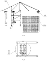
Fig. 1 is a front view of an embodiment of a container inspection system of the present disclosure. -
Fig. 2 is a top view of an inspection platform in an embodiment of a container inspection system of the present disclosure. -
Fig. 3 is a left view of an embodiment of a container inspection system of the present disclosure. -
Fig. 4 is a front view of another embodiment of a container inspection system of the present disclosure. -
Fig. 5 is an enlarged view of a part denoted by sign I inFigs. 1 and4 . -
Fig. 6 is an enlarged view of a part denoted by sign II inFig. 2 . -
- 100. quay crane; 200. inspection device; 300. container;
- 101. first hoisting component; 102. second hoisting component; 103. inspection platform; 104. first station; 105. second station; 106. first guide pillar; 107. second guide pillar;
- 201. cabin; 202. ray source; 203. horizonal arm; 204. vertical arm; 205. slewing bearing.
- The technical solutions in the embodiments will be described clearly and completely below in conjunction with the accompanying drawings in the embodiments of the present disclosure. Obviously, the described embodiments are only a part of the embodiments of the present disclosure, and not all the embodiments. Based on the embodiments of the present disclosure, all other embodiments obtained by those of ordinary skill in the art without creative work shall fall within the protection scope of the present disclosure.
- In description of the present disclosure, it should be understood that orientation or position relations denoted by the terms "center", "transverse", "longitudinal", "front", "rear", "left", "right", "upper", "lower", "vertical", "horizontal", "top", "bottom", "inner", "outer" and the like are orientation or position relations illustrated based on the drawings, are merely for the convenience of describing the present disclosure and simplifying description, instead of indicating or implying the denoted devices or elements must have specific orientations or be constructed and operated in specific orientations, and thus the terms cannot be understood as limiting the protection scope of the present disclosure.
- Referring to
Figs. 1 and5 , in an illustrative embodiment of a container inspection system provided by the present disclosure, the container inspection system includes aquay crane 100 and aninspection device 200, wherein thequay crane 100 includes afirst hoisting component 101 and aninspection platform 103 provided with a plurality of stations, thefirst hoisting component 101 being configured to hoist acontainer 300 and transport thecontainer 300 to at least one of the plurality of stations; and theinspection device 200 is disposed on theinspection platform 103 and configured to move relative to thecontainer 300 on each of the plurality of stations, to perform scanning inspection on thecontainer 300 on each of the plurality of stations, respectively. - The
inspection device 200 is disposed on theinspection platform 103, and thus may move with the movement of thequay crane 100; at the same time, theinspection device 200 may also move on theinspection platform 103 relative to thecontainer 300 on the station to perform scanning inspection on thecontainer 300. - In the above-mentioned illustrative embodiment, the
inspection device 200 may move relative to thecontainer 300 on each station, respectively, to perform scanning inspection on thecontainer 300 on each station, so that the inspection position of the container inspection system may be more flexible. Theinspection device 200 is not limited to scanning inspection at a specific station. After finishing scanning inspection on thecontainer 300 on one of the stations, theinspection device 200 may turn to another station and perform scanning inspection on thecontainer 300 on the another station, thus being beneficial to improving the efficiency of scanning inspection. - Furthermore, in the above-mentioned illustrative embodiment, by arranging the
inspection device 200 on theinspection platform 103 of thequay crane 100, a floor area occupied by theinspection device 200 may be reduced, and there is no need to reserve a special inspection location for theinspection device 200 in an area outside the quay crane, so that the overall layout of the port is more reasonable; and arranging theinspection device 200 on theinspection platform 103 of thequay crane 100 may also achieve the scanning inspection during the process of unloading thecontainer 300 from a ship or during the process of loading thecontainer 300 from the ground to a ship, to avoid in-yard inspection, and the process of transferring thecontainer 300 to an AGV trolley and transporting by the AGV trolley thecontainer 300 to an inspection location is omitted, thereby greatly reducing loading, unloading and scanning inspection time of thecontainer 300, shortening the total circulation time of thecontainer 300 at the port, and improving the circulation efficiency; this may also prevent dangerous prohibited articles from entering a yard, and improve the safety. - In the above-mentioned illustrative embodiment, during the scanning inspection, the
container 300 keeps stationary, and theinspection device 200 moves relative to thecontainer 300. Optionally, the container inspection system further includes a drive mechanism, which is configured to drive theinspection device 200 to move relative to thecontainer 300. - Optionally, guide rails are provided on two sides of each station, and the
inspection device 200 moves along the guide rails to ensure the accuracy of the movement route of theinspection device 200 and improve the accuracy of scanning inspection. - Further, the container inspection system further includes a switching mechanism, which is configured to switch the
inspection device 200 among the plurality of stations. - By providing the switching mechanism, the
inspection device 200 may quickly switch among the plurality of stations, and from an attitude capable of scanning inspecting on thecontainer 300 on one station to an attitude capable of scanning inspection on thecontainer 300 on another station, thereby improving the degree of automation of the container inspection system; moreover, after finishing scanning inspection on thecontainer 300 on one station, theinspection device 200 may quickly switch into a state of scanning inspection on thecontainer 300 on another station, instead of that after scanning inspection on the container on an inspection station is finished, it also needs to transfer the container from the inspection station to a temporary storage station, and wait for the next container to arrive at the inspection station so as to start scanning inspection on the next container like in the related art, thus greatly shortening the waiting time for theinspection device 200 to perform scanning inspection on the next container, and improving the scanning inspection efficiency. - In an optional embodiment, the switching mechanism includes a rotary switching mechanism, which is connected with the
inspection device 200, for rotating at least part of theinspection device 200, so that after finishing scanning inspection on thecontainer 300 on one of the plurality of stations, theinspection device 200 can perform scanning inspection on thecontainer 300 on another of the plurality of stations. - The rotary switching mechanism is simple in movement form and flexible in switching, which is beneficial to shortening the switching time and improving the efficiency of scanning inspection. The switch mechanism being configured to be rotary also enables the arrangement of the plurality of stations to be more convenient.
- Optionally, the plurality of stations include a
first station 104 and asecond station 105, wherein thefirst station 104 is arranged on a side of a long edge of thesecond station 105, and a long edge of thefirst station 104 and the long edge of thesecond station 105 are parallel to each other; and the switching mechanism is configured to rotate at least part of theinspection device 200 by 180 degrees. As shown inFigs. 5 and 6 , after finishing scanning inspection on thecontainer 300 on thefirst station 104, theinspection device 200 rotates 180 degrees and thereby can perform scanning inspection on thecontainer 300 on thesecond station 105. - The area ranges of the
first station 104 and thesecond station 105 are roughly similar to the shape of thecontainer 300. Generally speaking, thecontainer 300 is in the shape of a cuboid. The long edge of thefirst station 104 and the long edge of thesecond station 105 described above are parallel to a length direction of the container 300 (as a first direction). - Optionally, the plurality of stations may also include three stations, which are evenly arranged around the circumference. After finishing scanning inspection on the
container 300 on one station, theinspection device 200 may rotate 120 degrees to switch to scanning inspection on thecontainer 300 on another station adjacent thereto. - Of course, in the case where the plurality stations include four or more stations, the
inspection device 200 may also switch to scanning inspection on anothercontainer 300 by rotating an appropriate angle, which is not detailed here. - In the above-mentioned various embodiments, the
inspection device 200 optionally, but not limited to, moves in the length direction of thecontainer 300. - There may be multiple options for the specific structure of the
inspection device 200, so long as switching of theinspection device 200 between different stations can be achieved by the switching mechanism. - Optionally, the
inspection device 200 includes acabin 201, aray source 202 and an L-shaped arm installed with a detector, theray source 202 being disposed in thecabin 201 and rotatable relative to theinspection platform 103, and the L-shaped arm being mounted on thecabin 201 and rotatable relative to theinspection platform 103. - Specifically, the
inspection device 200 includes a rotation drive mechanism, which is configured to drive theray source 202 and/or the L-shaped arm to rotate relative to thecabin 201. - As shown in
Fig. 5 , the top of thecabin 201 is provided with aslewing bearing 205, wherein an outer ring of the slewing bearing 205 is connected with thecabin 201, an inner ring of the slewing bearing 205 is connected with a horizontally arrangedhorizonal arm 203 of the L-shaped arm, and a vertically arrangedvertical arm 204 is connected with thehorizonal arm 203. Rotation of the inner ring relative to the outer ring of the slewing bearing 205 may cause the L-shaped arm to rotate relative to thecabin 201, to achieve switching of theinspection device 200 between different stations. - The
slewing bearing 205 may be driven into rotation by a power device such as a hydraulic motor, a friction wheels, or a brake. - Correspondingly, a rotation mechanism may be provided between the
ray source 202 and thecabin 201, so that theray source 202 can also rotate relative to thecabin 201. This will not be detailed here. - In addition to the manner that the
cabin 201 is fixed relative to theinspection platform 103, and theray source 202 and the L-shaped arm rotate relative to theinspection platform 103, the switching of theinspection device 200 between different stations may also be achieved in such a manner that thecabin 201 rotates relative to theinspection platform 103 to cause theray source 202 and the L-shaped arm to rotate. The manner that thecabin 201 is fixed relative to theinspection platform 103 and theray source 202 and the L-shaped arm rotate relative to theinspection platform 103 is not limited by the shape of thecabin 201, and does not involve an increase in the spacing width between two stations due to a reserved space for rotation of thecabin 201. - In another optional embodiment, the plurality of stations include a
first station 104 and asecond station 105, wherein thefirst station 104 is arranged on a side of a short edge of thesecond station 105, and a short edge of thefirst station 104 and the short edge of thesecond station 105 are parallel to each other; and the switching mechanism includes a linear switching mechanism, which is connected with theinspection device 200, for enabling theinspection device 200 to continue to move along a long edge of thesecond station 105 after finishing scanning inspection on thecontainer 300 located on thefirst station 104, to perform scanning inspection on thecontainer 300 located on thesecond station 105. - The area ranges of the
first station 104 and thesecond station 105 are roughly similar to the shape of thecontainer 300. Generally speaking, thecontainer 300 is in the shape of a cuboid. The short edge of thefirst station 104 and the short edge of thesecond station 105 described above are parallel to a width direction of the container 300 (as a second direction). - The linear switching mechanism may be understood as a mechanism that causes the
inspection device 200 to move linearly. In the case where thefirst station 104 and thesecond station 105 are arranged in the above-mentioned manner, the linear switching mechanism may cause theinspection device 200 to move along the length direction of thecontainer 300 on thefirst station 104, and after finishing scanning inspection on thecontainer 300, continues to move along the length direction of thecontainer 300 on thesecond station 105 to perform scanning inspection on thecontainer 300 on thesecond station 105. - Specifically, the linear switching mechanism and the drive mechanism that drives the
inspection device 200 to move may be a same mechanism. Compared with a drive mechanism in a container inspection system performing scanning inspection only at an inspection station in the related art, the drive mechanism in the embodiment drives theinspection device 200 to move along a same direction for longer time. - In the above-mentioned various embodiments, the
first hoisting component 101 is further configured to hoist thecontainer 300 on which scanning inspection is completed from the station where the container is located and transport thecontainer 300 to a container transport equipment, so as to transport thecontainer 300 to a target location by the container transport equipment. - As to the above-mentioned target location, in the case where the container is unloaded from a cargo carrying equipment such as a ship, the target location may be a warehouse for storing containers on the ground of a yard of the port, or may also be a freight truck loaded with containers, etc.; and in the case where the container is loaded to a cargo carrying equipment such as a ship, the target location may be a storage bin for storing containers on the cargo carrying equipment such as a ship.
- In the case where the container is unloaded from a cargo carrying equipment such as a ship, the above-mentioned container transport equipment may be an AGV trolley, a container transport truck or the like. In the case where the container is loaded to a cargo carrying equipment such as a ship, the above-mentioned container moving equipment may be an equipment, disposed on the cargo carrying equipment such as a ship, for placing containers to corresponding storage bins.
- In other embodiments, the
quay crane 100 further includes asecond hoisting component 102 for hoisting thecontainer 300 on which scanning inspection is completed from the station where the container is located and transporting thecontainer 300 to a container transport equipment. That is, thefirst hoisting component 101 is configured to hoist thecontainer 300 and transport thecontainer 300 to at least one of the plurality of stations, and thesecond hoisting component 102 is configured to hoist thecontainer 300 on which scanning inspection is completed from the station where the container is located and transport thecontainer 300 to a container transport equipment. Thus, their respective responsibilities are clearer to facilitate control. - Optionally, the set height of the
second hoisting component 102 is lower than that of thefirst hoisting component 101 to avoid interference between the two hoisting components on travel routes, and also shorten the path for hoisting and moving away thecontainer 300 and improve the circulation efficiency. - Optionally, the container inspection system further includes a guide mechanism disposed on the
inspection platform 103, for guiding thecontainer 300 to fall in place on at least one of the plurality of stations. By providing the guide mechanism, thecontainer 300 may fall accurately; it may also limit thecontainer 300 to prevent thecontainer 300 from deviating from the station disposed on theinspection platform 103, and ensure thecontainer 300 may be accurately hoisted every time after thefirst hoisting component 101 or thesecond hoisting component 102 falls, thereby reducing the alignment time and improving the circulation efficiency. - As shown in
Figs. 5 and 6 , the guide mechanism includes a plurality of guide pillars having conic tops and arranged along edges of at least one of the plurality of stations, such that thecontainer 300 may be guided and positioned by the guide pillars. The tops of the guide pillars are cone-shaped, so that thecontainer 300 may be better guided to fall quickly and accurately. - Optionally, the guide mechanism is liftable relative to the
inspection platform 103. Thus, when thecontainer 300 falls, the guide mechanism may be raised to guide thecontainer 300; after thecontainer 300 falls in place, the and guide mechanism may be dropped to prevent the guide mechanism from influencing the movement of theinspection device 200; in addition, when theinspection device 200 switches between different stations, the and guide mechanism is dropped so that the guide mechanism may be prevented from interfering with the switching of theinspection device 200. - Optionally, the
inspection device 200 includes acabin 201, aray source 202 and an L-shaped arm installed with a detector, theray source 202 being disposed in thecabin 201, and the L-shaped arm being mounted on thecabin 201; and the guide mechanism includes a plurality offirst guide pillars 106 and a plurality ofsecond guide pillars 107, wherein thefirst guide pillars 106 are disposed on a side of the plurality of stations close to thecabin 201, the plurality offirst guide pillars 106 being non-liftable; and thesecond guide pillars 107 are disposed on a side of the plurality of stations away from thecabin 201, the plurality ofsecond guide pillars 107 being liftable. This arrangement may simplify the control as much as possible and improve the operation efficiency while ensuring the normal movement and switching of theinspection device 200. - Based on the above-mentioned container inspection system, the present disclosure further proposes a port facility, which includes the above-mentioned container inspection system. The positive technical effects of the container inspection system in the various embodiments described above are also applicable to the port facility and are not repeated here.
- The present disclosure further proposes a container inspection method, the inspection method including:
- hoisting and transporting, by a
first hoisting component 101 of aquay crane 100, acontainer 300 to at least one of a plurality of stations disposed on aninspection platform 103 of thequay crane 100; and - driving an
inspection device 200 disposed on theinspection platform 103 to move relative to thecontainer 300 on each of the plurality of stations to perform scanning inspection on thecontainer 300 on each station, respectively. - Further, the container inspection method further includes:
hoisting thecontainer 300 on which scanning inspection is completed from the station where the container is located and transporting thecontainer 300 to a container transport equipment. - Optionally, before driving the
inspection device 200 to move, the method may further include: detecting whether thecontainer 300 is in place; if yes, executing the step of driving theinspection device 200 to move; and if not, performing detection again until detecting that thecontainer 300 is in place. - A working process of an embodiment of the container inspection system, the port facility, and the container inspection method of the present disclosure will be described below in conjunction with
Figs. 1-6 :
As shown inFigs. 1-3 and5-6 , in an embodiment of the container inspection system provided by the present disclosure, the container inspection system includes aquay crane 100, and thequay crane 100 is provided with afirst hoisting component 101. Thefirst hoisting component 101 hoists thecontainer 300 from a container transport equipment such as a ship and places thecontainer 300 onto aninspection platform 103 disposed on thequay crane 100. - The
inspection platform 103 is provided with afirst station 104 and asecond station 105, the sizes of thefirst station 104 and thesecond station 105 being substantially same as the size of thecontainer 300. Generally, thecontainer 300 is in the shape of a cuboid. In this embodiment, thefirst station 104 is arranged on a side of a long edge of thesecond station 105, and a long edge of thefirst station 104 and the long edge of thesecond station 105 are parallel to each other; and a line connecting the center of thefirst station 104 and the center of thesecond station 105, and the long edge of thefirst station 104 are parallel to each other. - The
inspection device 200 includes acabin 201, and aray source 202 disposed in thecabin 201. The top of thecabin 201 is provided with aslewing bearing 205, wherein an outer ring of the slewing bearing 205 is connected with thecabin 201, and an inner ring of the slewing bearing 205 is connected with an L-shaped arm. The L-shaped arm is installed with a detector, and the L-shaped arm includes a horizontally arrangedhorizonal arm 203 and a vertically arrangedvertical arm 204. Thecabin 201 is arranged between thefirst station 104 and thesecond station 105, and the L-shaped arm spans across the stations on theinspection platform 103. - A plurality of
first guide pillars 106 are disposed on a side of thefirst station 104 away from thecabin 201 and on a side of thesecond station 105 away from thecabin 201, with a distance formed between every two adjacentfirst guide pillars 106, thefirst guide pillars 106 being liftable; and a plurality ofsecond guide pillars 107 are disposed on a side of thefirst station 104 close to thecabin 201 and on a side of thesecond station 105 close to thecabin 201, with a distance formed between every two adjacentsecond guide pillars 107, thesecond guide pillars 107 being non-liftable. - In another embodiment, as shown in
Fig. 4 , thequay crane 100 is further provided with asecond hoisting component 102. By means of thesecond hoisting component 102, thecontainer 300 on which scanning inspection is completed on thefirst station 104 or thesecond station 105 may be hoisted and transported to a container transport equipment such as an AGV trolley or a container transport truck at a port, and the container is transported to a target location by the container transport equipment. - Initially, supposing the
first station 104 and thesecond station 105 are both empty, acontainer 300 is hoisted and transported by thefirst hoisting component 101 from a ship to thefirst station 104, and after thecontainer 300 is detected to fall in place, theinspection device 200 is started and moves relative to thefirst station 104, to perform scanning inspection on thecontainer 300 on thefirst station 104; during the scanning inspection on thecontainer 300 on thefirst station 104, thefirst hoisting component 101 may hoist asecond container 300 from the ship and transport thesecond container 300 to thesecond station 105, and theinspection device 200 rotates 180 degrees after finishing scanning inspection on thecontainer 300 on thefirst station 104, and thevertical arm 204 rotates from the left side of thefirst station 104 to the right side of thesecond station 105, and theinspection device 200 may return to an initial end and then move relative to thesecond station 105, and perform scanning inspection on thecontainer 300 on thesecond station 105 during the movement, or theinspection device 200 may not return to the initial end first, but performs scanning inspection on thecontainer 300 on thesecond station 105 during returning to the initial end. - Of course, initially, if the
first station 104 and thesecond station 105 are both empty, it is also possible that acontainer 300 is hoisted and transported to thefirst station 104, and asecond container 300 is hoisted and transported to thesecond station 105, by thefirst hoisting component 101, and then theinspection device 200 is started. - During the scanning inspection on the
container 300 on thesecond station 105, thecontainer 300 on which scanning inspection is completed on thefirst station 104 may be hoisted and transported by thefirst hoisting component 101 or thesecond hoisting component 102 to an AGV trolley (or container transport truck) on the ground of the port, and then athird container 300 is hoisted and transported by thefirst hoisting component 101 from a ship to thefirst station 104, so that after finishing scanning inspection on thecontainer 300 on thesecond station 105, theinspection device 200 may continue, by switching, to perform scanning inspection on thethird container 300 on thefirst station 104. The process proceeds in this way to accomplish continuous scanning inspection onmultiple containers 300. - Before the
container 300 is hoisted and transported to thefirst station 104 or thesecond station 105, thefirst guide pillars 106 on the left side of thefirst station 104 and on the right side of thesecond station 105 rise to guide the falling process of thecontainer 300; after thecontainer 300 falls in place, thefirst guide pillars 106 fall to prevent thefirst guide pillars 106 from influencing the movement of theinspection device 200; moreover, when the L-shaped arm of theinspection device 200 rotates, thefirst guide pillars 106 also need to be in a fallen state, to avoid collision with thefirst guide pillars 106 during rotation the L-shaped arm. - From the description of multiple embodiments of the container inspection system, the port facility, and the container inspection method of the present disclosure, it can be seen the embodiments of the container inspection system, the port facility, and the container inspection method of the present disclosure have at least one or more of the following advantages:
- 1. the inspection platform is provided with a plurality of stations, and the inspection device may perform scanning inspection on the container on each station, respectively, so that the inspection position is more flexible, which is beneficial to improving the scanning inspection efficiency;
- 2. the switching mechanism is provided so that after scanning inspection on the container on one station is completed, the inspection device may switch to another station to perform scanning inspection on another container without secondary transfer, thereby effectively shorting the interval time and greatly improving the scanning inspection efficiency;
- 3. the inspection device is disposed on the quay crane, and performs scanning inspection during loading or unloading of the container, to avoid in-yard inspection, thereby simplifying the process, reducing the loading, unloading and scanning time, shortening the total circulation time of the container at the port, and improving the circulation efficiency; this also prevents prohibited articles from entering a yard; and by arranging the inspection device on the quay crane, a floor area may also be saved, and there is no need to reserve a special inspection location in an area outside the quay crane, so that the overall layout of the port is more reasonable; and
- 4. the guide mechanism provided on the stations may guide the container to fall in place to improve the falling accuracy.
- Described above are preferred implementations of the present disclosure, and it should be noted that to those of ordinary skill in the art, a number of improvements and modifications may also be made without departing from principles of the present disclosure, and these improvements and modifications should also be encompassed within the protection scope of the present disclosure.
Claims (15)
- A container inspection system, comprising:a quay crane (100), comprising:an inspection platform (103), provided with a plurality of stations; anda first hoisting component (101), for hoisting a container (300) and transporting the container (300) to at least one of the plurality of stations; andan inspection device (200), disposed on the inspection platform (103) and configured to switch among the plurality of stations, to perform scanning inspection on the container (300) on each of the plurality of stations, respectively.
- The container inspection system according to claim 1, further comprising:
a switching device, drivingly connecting with the inspection device (200) and configured to drive the inspection device (200) to rotate or perform linear motion relative to the inspection platform (103), so that the inspection device switches from one to another of the plurality of stations. - The container inspection system according to claim 2, wherein the plurality of stations comprise a first station (104) and a second station (105), the first station (104) being arranged on a side of the second station (105) along a first direction, the first direction being a length direction of the container (300); and the switching device is configured to drive the inspection device (200) to rotate 180 degrees relative to the inspection platform (103), to achieve switching of the inspection device (200) between the first station (104) and the second station (105).
- The container inspection system according to claim 3, wherein the inspection device (200) comprises:a cabin (201);a ray source (202), disposed in the cabin (201) and rotatable relative to the inspection platform (103);an L-shaped arm, mounted on the cabin (201) and rotatable relative to the inspection platform (103); anda detector mounted on the L-shaped arm.
- The container inspection system according to claim 2, wherein the plurality of stations comprise a first station (104) and a second station (105), the first station (104) being arranged on a side of the second station (105) along a second direction, the second direction being a width direction of the container (300); and the switching device is configured to drive the inspection device (200) to perform linear motion along a first direction, to achieve switching of the inspection device (200) between the first station (104) and the second station (105), the first direction being a length direction of the container (300).
- The container inspection system according to claim 1, wherein the first hoisting component (101) is configured to hoist the container (300) on which scanning inspection is completed from a station where the container (300) is located and transporting the container (300) to a container transport equipment.
- The container inspection system according to claim 1, wherein the quay crane (100) further comprises:
a second hoisting component (102), for hoisting the container (300) on which scanning inspection is completed from a station where the container (300) is located and transporting the container (300) to a container transport equipment. - The container inspection system according to claim 1, further comprising:
a guide mechanism, disposed on the inspection platform (103), for guiding the container (300) to fall in place on at least one of the plurality of stations. - The container inspection system according to claim 8, wherein the guide mechanism comprises:
a plurality of guide pillars, with conic tops and being arranged along edges of at least one of the plurality of stations. - The container inspection system according to claim 8, wherein the guide mechanism is liftable relative to the inspection platform (103).
- The container inspection system according to claim 8, wherein the inspection device (200) comprises a cabin (201), a ray source (202) and an L-shaped arm installed with a detector, the ray source (202) being disposed in the cabin (201), and the L-shaped arm being mounted on the cabin (201); and the guide mechanism comprises:a plurality of first guide pillars (106), disposed on a side of the plurality of stations close to the cabin (201), the plurality of first guide pillars (106) being non-liftable; anda plurality of second guide pillars (107), disposed on a side of the plurality of stations away from the cabin (201), the plurality of second guide pillars (107) being liftable.
- A port facility, comprising the container inspection system of any one of claims 1-11.
- A container inspection method, comprising:hoisting and transporting, by a first hoisting component (101) of a quay crane (100), a container (300) to at least one of a plurality of stations disposed on an inspection platform (103) of the quay crane (100); anddriving an inspection device (200) disposed on the inspection platform (103) to switch among the plurality of stations, to perform scanning inspection on the container (300) on each of the plurality of stations, respectively.
- The container inspection method according to claim 13, wherein driving an inspection device (200) disposed on the inspection platform (103) to switch among the plurality of stations comprises:
driving the inspection device (200) disposed on the inspection platform (103) to rotate or perform linear motion relative to the inspection platform (103), so that the inspection device switches from one to another of the plurality of stations. - The container inspection method according to claim 13, further comprising:
hoisting the container (300) on which scanning inspection is completed from a station where the container (300) is located and transporting the container (300) to a container transport equipment.
Applications Claiming Priority (2)
| Application Number | Priority Date | Filing Date | Title |
|---|---|---|---|
| CN201810426091.3A CN108873088A (en) | 2018-05-07 | 2018-05-07 | Container check system, port facilities and inspection of containers method |
| PCT/CN2019/079916 WO2019214357A1 (en) | 2018-05-07 | 2019-03-27 | Container inspection system, port facility and container inspection method |
Publications (3)
| Publication Number | Publication Date |
|---|---|
| EP3792667A1 true EP3792667A1 (en) | 2021-03-17 |
| EP3792667A4 EP3792667A4 (en) | 2022-01-19 |
| EP3792667B1 EP3792667B1 (en) | 2024-09-18 |
Family
ID=64327436
Family Applications (1)
| Application Number | Title | Priority Date | Filing Date |
|---|---|---|---|
| EP19799514.5A Active EP3792667B1 (en) | 2018-05-07 | 2019-03-27 | Container inspection system, port facility and container inspection method |
Country Status (3)
| Country | Link |
|---|---|
| EP (1) | EP3792667B1 (en) |
| CN (1) | CN108873088A (en) |
| WO (1) | WO2019214357A1 (en) |
Families Citing this family (5)
| Publication number | Priority date | Publication date | Assignee | Title |
|---|---|---|---|---|
| CN108508496A (en) * | 2018-04-04 | 2018-09-07 | 同方威视技术股份有限公司 | Container check system, port facilities and inspection of containers method |
| CN108873088A (en) * | 2018-05-07 | 2018-11-23 | 同方威视技术股份有限公司 | Container check system, port facilities and inspection of containers method |
| CN108415095A (en) * | 2018-05-09 | 2018-08-17 | 清华大学 | Vehicle inspection system |
| CN114384596B (en) * | 2020-10-22 | 2023-08-29 | 同方威视技术股份有限公司 | Vehicle security inspection system, vehicle security inspection system combination and security inspection method |
| CN113341475B (en) * | 2021-07-02 | 2025-09-19 | 同方威视技术股份有限公司 | Inspection apparatus and article transfer inspection system |
Family Cites Families (17)
| Publication number | Priority date | Publication date | Assignee | Title |
|---|---|---|---|---|
| DE10160928A1 (en) * | 2001-12-12 | 2003-06-26 | Noell Crane Sys Gmbh | Device and method for contactless load control on crane systems |
| US7317782B2 (en) * | 2003-01-31 | 2008-01-08 | Varian Medical Systems Technologies, Inc. | Radiation scanning of cargo conveyances at seaports and the like |
| DE10313248A1 (en) * | 2003-03-25 | 2004-11-11 | Noell Crane Systems Gmbh | Mobile multi-functional platform for contactless load scanning and transporting of containers has crane on platform for transferring of containers, an X-ray unit, a screen movable over and along container, and wheels for platform |
| US6845873B1 (en) * | 2003-07-17 | 2005-01-25 | Nigel Chattey | Crane apparatus equipped with container security scanning system |
| US7267239B2 (en) * | 2003-08-12 | 2007-09-11 | Toru Takehara | Method for nonintrusive scanning of cargo containers in a buffer operation |
| US7677857B2 (en) * | 2003-08-12 | 2010-03-16 | Paceco Corp. | Mobile cargo container scanning buffer crane |
| JP4274980B2 (en) * | 2004-03-10 | 2009-06-10 | 三井造船株式会社 | Container cargo inspection equipment |
| CN2840027Y (en) * | 2005-09-20 | 2006-11-22 | 赵景岐 | A kind of binary channels combination moving type container or vehicle inspection system |
| CN101062747A (en) * | 2006-04-25 | 2007-10-31 | 宋世鹏 | Container crane |
| EP2670691A2 (en) * | 2011-02-03 | 2013-12-11 | Raadgevend Ingenieursburo F. Koch B.V. | Unloading and loading crane arrangement and assembly of two unloading and loading crane arrangements |
| CN203705662U (en) * | 2013-12-26 | 2014-07-09 | 同方威视技术股份有限公司 | Inspection system for containers |
| CN104749198B (en) * | 2013-12-30 | 2019-08-06 | 同方威视技术股份有限公司 | Binary channels sigmatron fluoroscopy imaging system |
| CN206020303U (en) * | 2016-08-31 | 2017-03-15 | 同方威视技术股份有限公司 | Portable commodity inspection system and harbour |
| CN106226336A (en) * | 2016-08-31 | 2016-12-14 | 同方威视技术股份有限公司 | Portable commodity inspection system, method and harbour |
| CN107860782A (en) * | 2017-09-22 | 2018-03-30 | 北京华力兴科技发展有限责任公司 | Portable commodity inspection system |
| CN208239633U (en) * | 2018-05-07 | 2018-12-14 | 同方威视技术股份有限公司 | Container check system and port facilities |
| CN108873088A (en) * | 2018-05-07 | 2018-11-23 | 同方威视技术股份有限公司 | Container check system, port facilities and inspection of containers method |
-
2018
- 2018-05-07 CN CN201810426091.3A patent/CN108873088A/en active Pending
-
2019
- 2019-03-27 WO PCT/CN2019/079916 patent/WO2019214357A1/en not_active Ceased
- 2019-03-27 EP EP19799514.5A patent/EP3792667B1/en active Active
Also Published As
| Publication number | Publication date |
|---|---|
| EP3792667A4 (en) | 2022-01-19 |
| CN108873088A (en) | 2018-11-23 |
| EP3792667B1 (en) | 2024-09-18 |
| WO2019214357A1 (en) | 2019-11-14 |
Similar Documents
| Publication | Publication Date | Title |
|---|---|---|
| EP3792667B1 (en) | Container inspection system, port facility and container inspection method | |
| JP6215323B2 (en) | Elevated crane and assembly of at least two elevated cranes | |
| JP4142850B2 (en) | Transshipment facilities for small cargo, especially ISO containers | |
| US20200346863A1 (en) | System for the transfer, storage and distribution of intermodal containers | |
| EP3786099B1 (en) | Container inspection system, port facility, and container inspection method | |
| CN106029547B (en) | A stacking crane with an intermediate storage area for containers | |
| WO2012133278A1 (en) | Container terminal and control method therefor | |
| WO2013169110A1 (en) | Overhead crane, assembly of at least two overhead cranes, automated guided vehicle, and assembly thereof | |
| SG185151A1 (en) | Auto stevedore robotic cell | |
| CN107860782A (en) | Portable commodity inspection system | |
| CN110482270B (en) | cargo loading method | |
| PL247665B1 (en) | Container inspection system, transferring method and port facility | |
| JP4171024B2 (en) | Cargo handling facilities at the port or inner port | |
| EP2743217B1 (en) | Loading and unloading system for containers at quayside | |
| CN208239633U (en) | Container check system and port facilities | |
| JP7323873B2 (en) | container terminal | |
| CN107399621B (en) | Shore loading and unloading equipment and loading and unloading method | |
| EP3779519B1 (en) | Container inspection system, port facility, and container inspection method | |
| KR102273793B1 (en) | Smart logistics transfortation system | |
| JP2002145453A (en) | Container storage device | |
| CN208092257U (en) | Container check system and port facilities | |
| CN208092256U (en) | Container check system and port facilities | |
| JP2008528355A (en) | Cargo handling device and system in cargo ship | |
| US10611583B2 (en) | Straddle-type multimodal transportation interworking system | |
| Liu | Research on new structural quay container crane |
Legal Events
| Date | Code | Title | Description |
|---|---|---|---|
| STAA | Information on the status of an ep patent application or granted ep patent |
Free format text: STATUS: THE INTERNATIONAL PUBLICATION HAS BEEN MADE |
|
| PUAI | Public reference made under article 153(3) epc to a published international application that has entered the european phase |
Free format text: ORIGINAL CODE: 0009012 |
|
| STAA | Information on the status of an ep patent application or granted ep patent |
Free format text: STATUS: REQUEST FOR EXAMINATION WAS MADE |
|
| 17P | Request for examination filed |
Effective date: 20201130 |
|
| AK | Designated contracting states |
Kind code of ref document: A1 Designated state(s): AL AT BE BG CH CY CZ DE DK EE ES FI FR GB GR HR HU IE IS IT LI LT LU LV MC MK MT NL NO PL PT RO RS SE SI SK SM TR |
|
| AX | Request for extension of the european patent |
Extension state: BA ME |
|
| DAV | Request for validation of the european patent (deleted) | ||
| DAX | Request for extension of the european patent (deleted) | ||
| RIN1 | Information on inventor provided before grant (corrected) |
Inventor name: LI, YUANJING Inventor name: ZONG, CHUNGUANG Inventor name: SHI, JUNPING Inventor name: SONG, QUANWEI Inventor name: MENG, HUI Inventor name: GUO, YIWEI Inventor name: GU, JINGYU Inventor name: LI, YING Inventor name: SUN, SHANGMIN Inventor name: LI, JIANMIN Inventor name: CHEN, ZHIQIANG |
|
| A4 | Supplementary search report drawn up and despatched |
Effective date: 20211222 |
|
| RIC1 | Information provided on ipc code assigned before grant |
Ipc: G01V 5/00 20060101AFI20211216BHEP |
|
| STAA | Information on the status of an ep patent application or granted ep patent |
Free format text: STATUS: EXAMINATION IS IN PROGRESS |
|
| REG | Reference to a national code |
Ref country code: DE Ref legal event code: R079 Free format text: PREVIOUS MAIN CLASS: G01V0005000000 Ipc: G01V0005220000 Ref document number: 602019059157 Country of ref document: DE |
|
| 17Q | First examination report despatched |
Effective date: 20240229 |
|
| GRAP | Despatch of communication of intention to grant a patent |
Free format text: ORIGINAL CODE: EPIDOSNIGR1 |
|
| STAA | Information on the status of an ep patent application or granted ep patent |
Free format text: STATUS: GRANT OF PATENT IS INTENDED |
|
| RIC1 | Information provided on ipc code assigned before grant |
Ipc: G01V 5/22 20240101AFI20240326BHEP |
|
| INTG | Intention to grant announced |
Effective date: 20240411 |
|
| GRAS | Grant fee paid |
Free format text: ORIGINAL CODE: EPIDOSNIGR3 |
|
| GRAA | (expected) grant |
Free format text: ORIGINAL CODE: 0009210 |
|
| STAA | Information on the status of an ep patent application or granted ep patent |
Free format text: STATUS: THE PATENT HAS BEEN GRANTED |
|
| AK | Designated contracting states |
Kind code of ref document: B1 Designated state(s): AL AT BE BG CH CY CZ DE DK EE ES FI FR GB GR HR HU IE IS IT LI LT LU LV MC MK MT NL NO PL PT RO RS SE SI SK SM TR |
|
| REG | Reference to a national code |
Ref country code: GB Ref legal event code: FG4D |
|
| REG | Reference to a national code |
Ref country code: CH Ref legal event code: EP |
|
| REG | Reference to a national code |
Ref country code: DE Ref legal event code: R096 Ref document number: 602019059157 Country of ref document: DE |
|
| REG | Reference to a national code |
Ref country code: IE Ref legal event code: FG4D |
|
| REG | Reference to a national code |
Ref country code: LT Ref legal event code: MG9D |
|
| PG25 | Lapsed in a contracting state [announced via postgrant information from national office to epo] |
Ref country code: NO Free format text: LAPSE BECAUSE OF FAILURE TO SUBMIT A TRANSLATION OF THE DESCRIPTION OR TO PAY THE FEE WITHIN THE PRESCRIBED TIME-LIMIT Effective date: 20241218 |
|
| PG25 | Lapsed in a contracting state [announced via postgrant information from national office to epo] |
Ref country code: GR Free format text: LAPSE BECAUSE OF FAILURE TO SUBMIT A TRANSLATION OF THE DESCRIPTION OR TO PAY THE FEE WITHIN THE PRESCRIBED TIME-LIMIT Effective date: 20241219 Ref country code: FI Free format text: LAPSE BECAUSE OF FAILURE TO SUBMIT A TRANSLATION OF THE DESCRIPTION OR TO PAY THE FEE WITHIN THE PRESCRIBED TIME-LIMIT Effective date: 20240918 |
|
| PG25 | Lapsed in a contracting state [announced via postgrant information from national office to epo] |
Ref country code: BG Free format text: LAPSE BECAUSE OF FAILURE TO SUBMIT A TRANSLATION OF THE DESCRIPTION OR TO PAY THE FEE WITHIN THE PRESCRIBED TIME-LIMIT Effective date: 20240918 |
|
| PG25 | Lapsed in a contracting state [announced via postgrant information from national office to epo] |
Ref country code: LV Free format text: LAPSE BECAUSE OF FAILURE TO SUBMIT A TRANSLATION OF THE DESCRIPTION OR TO PAY THE FEE WITHIN THE PRESCRIBED TIME-LIMIT Effective date: 20240918 |
|
| PG25 | Lapsed in a contracting state [announced via postgrant information from national office to epo] |
Ref country code: HR Free format text: LAPSE BECAUSE OF FAILURE TO SUBMIT A TRANSLATION OF THE DESCRIPTION OR TO PAY THE FEE WITHIN THE PRESCRIBED TIME-LIMIT Effective date: 20240918 |
|
| REG | Reference to a national code |
Ref country code: NL Ref legal event code: MP Effective date: 20240918 |
|
| PG25 | Lapsed in a contracting state [announced via postgrant information from national office to epo] |
Ref country code: RS Free format text: LAPSE BECAUSE OF FAILURE TO SUBMIT A TRANSLATION OF THE DESCRIPTION OR TO PAY THE FEE WITHIN THE PRESCRIBED TIME-LIMIT Effective date: 20241218 |
|
| PG25 | Lapsed in a contracting state [announced via postgrant information from national office to epo] |
Ref country code: RS Free format text: LAPSE BECAUSE OF FAILURE TO SUBMIT A TRANSLATION OF THE DESCRIPTION OR TO PAY THE FEE WITHIN THE PRESCRIBED TIME-LIMIT Effective date: 20241218 Ref country code: NO Free format text: LAPSE BECAUSE OF FAILURE TO SUBMIT A TRANSLATION OF THE DESCRIPTION OR TO PAY THE FEE WITHIN THE PRESCRIBED TIME-LIMIT Effective date: 20241218 Ref country code: LV Free format text: LAPSE BECAUSE OF FAILURE TO SUBMIT A TRANSLATION OF THE DESCRIPTION OR TO PAY THE FEE WITHIN THE PRESCRIBED TIME-LIMIT Effective date: 20240918 Ref country code: HR Free format text: LAPSE BECAUSE OF FAILURE TO SUBMIT A TRANSLATION OF THE DESCRIPTION OR TO PAY THE FEE WITHIN THE PRESCRIBED TIME-LIMIT Effective date: 20240918 Ref country code: GR Free format text: LAPSE BECAUSE OF FAILURE TO SUBMIT A TRANSLATION OF THE DESCRIPTION OR TO PAY THE FEE WITHIN THE PRESCRIBED TIME-LIMIT Effective date: 20241219 Ref country code: FI Free format text: LAPSE BECAUSE OF FAILURE TO SUBMIT A TRANSLATION OF THE DESCRIPTION OR TO PAY THE FEE WITHIN THE PRESCRIBED TIME-LIMIT Effective date: 20240918 Ref country code: BG Free format text: LAPSE BECAUSE OF FAILURE TO SUBMIT A TRANSLATION OF THE DESCRIPTION OR TO PAY THE FEE WITHIN THE PRESCRIBED TIME-LIMIT Effective date: 20240918 |
|
| REG | Reference to a national code |
Ref country code: AT Ref legal event code: MK05 Ref document number: 1725169 Country of ref document: AT Kind code of ref document: T Effective date: 20240918 |
|
| PG25 | Lapsed in a contracting state [announced via postgrant information from national office to epo] |
Ref country code: NL Free format text: LAPSE BECAUSE OF FAILURE TO SUBMIT A TRANSLATION OF THE DESCRIPTION OR TO PAY THE FEE WITHIN THE PRESCRIBED TIME-LIMIT Effective date: 20240918 |
|
| PG25 | Lapsed in a contracting state [announced via postgrant information from national office to epo] |
Ref country code: IS Free format text: LAPSE BECAUSE OF FAILURE TO SUBMIT A TRANSLATION OF THE DESCRIPTION OR TO PAY THE FEE WITHIN THE PRESCRIBED TIME-LIMIT Effective date: 20250118 Ref country code: PT Free format text: LAPSE BECAUSE OF FAILURE TO SUBMIT A TRANSLATION OF THE DESCRIPTION OR TO PAY THE FEE WITHIN THE PRESCRIBED TIME-LIMIT Effective date: 20250120 |
|
| PG25 | Lapsed in a contracting state [announced via postgrant information from national office to epo] |
Ref country code: SM Free format text: LAPSE BECAUSE OF FAILURE TO SUBMIT A TRANSLATION OF THE DESCRIPTION OR TO PAY THE FEE WITHIN THE PRESCRIBED TIME-LIMIT Effective date: 20240918 Ref country code: RO Free format text: LAPSE BECAUSE OF FAILURE TO SUBMIT A TRANSLATION OF THE DESCRIPTION OR TO PAY THE FEE WITHIN THE PRESCRIBED TIME-LIMIT Effective date: 20240918 |
|
| PG25 | Lapsed in a contracting state [announced via postgrant information from national office to epo] |
Ref country code: ES Free format text: LAPSE BECAUSE OF FAILURE TO SUBMIT A TRANSLATION OF THE DESCRIPTION OR TO PAY THE FEE WITHIN THE PRESCRIBED TIME-LIMIT Effective date: 20240918 |
|
| PG25 | Lapsed in a contracting state [announced via postgrant information from national office to epo] |
Ref country code: EE Free format text: LAPSE BECAUSE OF FAILURE TO SUBMIT A TRANSLATION OF THE DESCRIPTION OR TO PAY THE FEE WITHIN THE PRESCRIBED TIME-LIMIT Effective date: 20240918 Ref country code: AT Free format text: LAPSE BECAUSE OF FAILURE TO SUBMIT A TRANSLATION OF THE DESCRIPTION OR TO PAY THE FEE WITHIN THE PRESCRIBED TIME-LIMIT Effective date: 20240918 |
|
| PG25 | Lapsed in a contracting state [announced via postgrant information from national office to epo] |
Ref country code: PL Free format text: LAPSE BECAUSE OF FAILURE TO SUBMIT A TRANSLATION OF THE DESCRIPTION OR TO PAY THE FEE WITHIN THE PRESCRIBED TIME-LIMIT Effective date: 20240918 Ref country code: CZ Free format text: LAPSE BECAUSE OF FAILURE TO SUBMIT A TRANSLATION OF THE DESCRIPTION OR TO PAY THE FEE WITHIN THE PRESCRIBED TIME-LIMIT Effective date: 20240918 |
|
| PG25 | Lapsed in a contracting state [announced via postgrant information from national office to epo] |
Ref country code: SK Free format text: LAPSE BECAUSE OF FAILURE TO SUBMIT A TRANSLATION OF THE DESCRIPTION OR TO PAY THE FEE WITHIN THE PRESCRIBED TIME-LIMIT Effective date: 20240918 Ref country code: IT Free format text: LAPSE BECAUSE OF FAILURE TO SUBMIT A TRANSLATION OF THE DESCRIPTION OR TO PAY THE FEE WITHIN THE PRESCRIBED TIME-LIMIT Effective date: 20240918 |
|
| REG | Reference to a national code |
Ref country code: DE Ref legal event code: R097 Ref document number: 602019059157 Country of ref document: DE |
|
| PG25 | Lapsed in a contracting state [announced via postgrant information from national office to epo] |
Ref country code: DK Free format text: LAPSE BECAUSE OF FAILURE TO SUBMIT A TRANSLATION OF THE DESCRIPTION OR TO PAY THE FEE WITHIN THE PRESCRIBED TIME-LIMIT Effective date: 20240918 |
|
| PLBE | No opposition filed within time limit |
Free format text: ORIGINAL CODE: 0009261 |
|
| STAA | Information on the status of an ep patent application or granted ep patent |
Free format text: STATUS: NO OPPOSITION FILED WITHIN TIME LIMIT |
|
| 26N | No opposition filed |
Effective date: 20250619 |
|
| PG25 | Lapsed in a contracting state [announced via postgrant information from national office to epo] |
Ref country code: SE Free format text: LAPSE BECAUSE OF FAILURE TO SUBMIT A TRANSLATION OF THE DESCRIPTION OR TO PAY THE FEE WITHIN THE PRESCRIBED TIME-LIMIT Effective date: 20240918 |
|
| REG | Reference to a national code |
Ref country code: DE Ref legal event code: R119 Ref document number: 602019059157 Country of ref document: DE |
|
| PG25 | Lapsed in a contracting state [announced via postgrant information from national office to epo] |
Ref country code: MC Free format text: LAPSE BECAUSE OF FAILURE TO SUBMIT A TRANSLATION OF THE DESCRIPTION OR TO PAY THE FEE WITHIN THE PRESCRIBED TIME-LIMIT Effective date: 20240918 |
|
| REG | Reference to a national code |
Ref country code: CH Ref legal event code: H13 Free format text: ST27 STATUS EVENT CODE: U-0-0-H10-H13 (AS PROVIDED BY THE NATIONAL OFFICE) Effective date: 20251023 |
|
| PG25 | Lapsed in a contracting state [announced via postgrant information from national office to epo] |
Ref country code: LU Free format text: LAPSE BECAUSE OF NON-PAYMENT OF DUE FEES Effective date: 20250327 |
|
| GBPC | Gb: european patent ceased through non-payment of renewal fee |
Effective date: 20250327 |
|
| REG | Reference to a national code |
Ref country code: BE Ref legal event code: MM Effective date: 20250331 |
|
| PG25 | Lapsed in a contracting state [announced via postgrant information from national office to epo] |
Ref country code: DE Free format text: LAPSE BECAUSE OF NON-PAYMENT OF DUE FEES Effective date: 20251001 |
|
| PG25 | Lapsed in a contracting state [announced via postgrant information from national office to epo] |
Ref country code: GB Free format text: LAPSE BECAUSE OF NON-PAYMENT OF DUE FEES Effective date: 20250327 |
|
| PG25 | Lapsed in a contracting state [announced via postgrant information from national office to epo] |
Ref country code: FR Free format text: LAPSE BECAUSE OF NON-PAYMENT OF DUE FEES Effective date: 20250331 |
|
| PG25 | Lapsed in a contracting state [announced via postgrant information from national office to epo] |
Ref country code: BE Free format text: LAPSE BECAUSE OF NON-PAYMENT OF DUE FEES Effective date: 20250331 |
|
| PG25 | Lapsed in a contracting state [announced via postgrant information from national office to epo] |
Ref country code: CH Free format text: LAPSE BECAUSE OF NON-PAYMENT OF DUE FEES Effective date: 20250331 |
|
| PG25 | Lapsed in a contracting state [announced via postgrant information from national office to epo] |
Ref country code: IE Free format text: LAPSE BECAUSE OF NON-PAYMENT OF DUE FEES Effective date: 20250327 |
|
| PG25 | Lapsed in a contracting state [announced via postgrant information from national office to epo] |
Ref country code: CY Free format text: LAPSE BECAUSE OF FAILURE TO SUBMIT A TRANSLATION OF THE DESCRIPTION OR TO PAY THE FEE WITHIN THE PRESCRIBED TIME-LIMIT Effective date: 20240918 |
|
| PG25 | Lapsed in a contracting state [announced via postgrant information from national office to epo] |
Ref country code: LT Free format text: LAPSE BECAUSE OF FAILURE TO SUBMIT A TRANSLATION OF THE DESCRIPTION OR TO PAY THE FEE WITHIN THE PRESCRIBED TIME-LIMIT Effective date: 20240918 |
|
| PG25 | Lapsed in a contracting state [announced via postgrant information from national office to epo] |
Ref country code: TR Free format text: LAPSE BECAUSE OF FAILURE TO SUBMIT A TRANSLATION OF THE DESCRIPTION OR TO PAY THE FEE WITHIN THE PRESCRIBED TIME-LIMIT Effective date: 20240918 |