EP3792144B1 - Schubkarre ausgestattet mit einem schwenkbaren greifsystem - Google Patents
Schubkarre ausgestattet mit einem schwenkbaren greifsystem Download PDFInfo
- Publication number
- EP3792144B1 EP3792144B1 EP20193214.2A EP20193214A EP3792144B1 EP 3792144 B1 EP3792144 B1 EP 3792144B1 EP 20193214 A EP20193214 A EP 20193214A EP 3792144 B1 EP3792144 B1 EP 3792144B1
- Authority
- EP
- European Patent Office
- Prior art keywords
- gripping
- wheelbarrow
- handle
- gripping system
- curved section
- Prior art date
- Legal status (The legal status is an assumption and is not a legal conclusion. Google has not performed a legal analysis and makes no representation as to the accuracy of the status listed.)
- Active
Links
Images


Classifications
-
- B—PERFORMING OPERATIONS; TRANSPORTING
- B62—LAND VEHICLES FOR TRAVELLING OTHERWISE THAN ON RAILS
- B62B—HAND-PROPELLED VEHICLES, e.g. HAND CARTS OR PERAMBULATORS; SLEDGES
- B62B1/00—Hand carts having only one axis carrying one or more transport wheels; Equipment therefor
- B62B1/18—Hand carts having only one axis carrying one or more transport wheels; Equipment therefor in which the load is disposed between the wheel axis and the handles, e.g. wheelbarrows
- B62B1/20—Hand carts having only one axis carrying one or more transport wheels; Equipment therefor in which the load is disposed between the wheel axis and the handles, e.g. wheelbarrows involving parts being collapsible, attachable, detachable or convertible
- B62B1/208—Hand carts having only one axis carrying one or more transport wheels; Equipment therefor in which the load is disposed between the wheel axis and the handles, e.g. wheelbarrows involving parts being collapsible, attachable, detachable or convertible foldable
-
- B—PERFORMING OPERATIONS; TRANSPORTING
- B62—LAND VEHICLES FOR TRAVELLING OTHERWISE THAN ON RAILS
- B62B—HAND-PROPELLED VEHICLES, e.g. HAND CARTS OR PERAMBULATORS; SLEDGES
- B62B5/00—Accessories or details specially adapted for hand carts
- B62B5/06—Hand moving equipment, e.g. handle bars
- B62B5/067—Stowable or retractable handle bars
-
- B—PERFORMING OPERATIONS; TRANSPORTING
- B62—LAND VEHICLES FOR TRAVELLING OTHERWISE THAN ON RAILS
- B62B—HAND-PROPELLED VEHICLES, e.g. HAND CARTS OR PERAMBULATORS; SLEDGES
- B62B2203/00—Grasping, holding, supporting the objects
- B62B2203/05—Rocking means for facilitating tilting of the cart, e.g. by loading
-
- B—PERFORMING OPERATIONS; TRANSPORTING
- B62—LAND VEHICLES FOR TRAVELLING OTHERWISE THAN ON RAILS
- B62B—HAND-PROPELLED VEHICLES, e.g. HAND CARTS OR PERAMBULATORS; SLEDGES
- B62B2205/00—Hand-propelled vehicles or sledges being foldable or dismountable when not in use
- B62B2205/20—Catches; Locking or releasing an articulation
-
- B—PERFORMING OPERATIONS; TRANSPORTING
- B62—LAND VEHICLES FOR TRAVELLING OTHERWISE THAN ON RAILS
- B62B—HAND-PROPELLED VEHICLES, e.g. HAND CARTS OR PERAMBULATORS; SLEDGES
- B62B5/00—Accessories or details specially adapted for hand carts
- B62B5/06—Hand moving equipment, e.g. handle bars
- B62B5/062—Hand moving equipment, e.g. handle bars elastically mounted, e.g. for wheelbarrows
Definitions
- the invention relates to the field of wheelbarrows, and more particularly wheelbarrows provided with pivoting handles.
- wheelbarrow we mean a handling device mounted on one or more wheels, equipped with two stretchers allowing it to be gripped by the user, and comprising a container intended to receive a load to be moved from one place to another.
- Moving a load using a wheelbarrow imposes significant physical effort on the user. Such efforts are for example exerted when the user lifts the loaded wheelbarrow using the handles, and moves the assembly. At the same time, the user must maintain the balance of the load by operating the handles. Furthermore, when dumping the transported loads, the user is generally required to tip the container forward, lifting the handles upwards, which places a strong strain on the upper parts of the user's body.
- MSD musculoskeletal disorders
- the factors favoring the occurrence of MSDs are multiple, and are often classified into three main components, namely organizational factors linked to the organization of work, psychosocial factors referring to the quality of the work environment as perceived by workers, and biomechanical or physical factors, relating to physical constraints at work (see for example Herquelot thesis, Occupational risk factors for musculoskeletal disorders of the elbows and knees, 2015 ).
- the labor code requires that a load greater than 55 kg cannot be carried by a male individual without medical advice, the maximum load in such a case not being able to exceed 105 kg.
- the maximum load is reported at 25 kg, and 40 kg with a wheelbarrow, including the weight of the wheelbarrow.
- the NF X35-109 standard relating to ergonomics in the manual handling of loads which defines reference values, applicable without distinction to men and women aged 18 to 65, recommends a value of 15 kg of load per operation for lifting/carrying activities, limited to 7.5 tonnes per day per person when it appears that it is not possible to eliminate manual handling operations.
- MSDs it is sought to act on the ergonomics of the workstation and tools, so as to avoid making movements that could lead to the occurrence of MSDs. For example, extreme joint positions combined with excessive and repetitive strain have been identified as factors favoring the appearance of MSDs.
- the document US 5153966 (Godwin ) describes a wheelbarrow handle having a loop shape. In this way, the user can lift the wheelbarrow, and hold the wheelbarrow in the unloading position, without bending the wrists. However, the user must bend their wrists to lift the wheelbarrow, or change the position of their wrists during unloading.
- the document US 5799960 (Davis ) describes a wheelbarrow comprising a gripping mechanism provided with rotating handles mounted perpendicular to the ends of the stretchers, which can be connected together, forming a crossbar.
- the user does not need to rotate their wrists.
- the use of handles extending transversely has the effect of exerting a load tending to flex the wrist.
- Such flexion of the wrist can be restrictive, and lead to the risk of MSDs occurring if the load carried is too great.
- protruding handles have the disadvantage of creating hooking points which can be annoying for the user.
- Using a crossbar may create an obstacle when handling the wheelbarrow.
- Such handles are each independently linked in rotation to each stretcher of the wheelbarrow.
- Such handles include a gripping part, allowing the user to grasp the handle, and a connecting part, the connecting part being connected to the stretcher via an axis of rotation.
- the tilting handles move between a raised position, the connecting parts abutting against the end of the stretcher, so as to allow the wheelbarrow to move, and a lowered position used when the wheelbarrow tilts during unloading.
- handles make it possible to limit the effort of dumping.
- the handles can pivot when a user places themselves, for example, in a turn.
- the document US 2011/272924 refers to wheelbarrows incorporating a brake and a bowl locking mechanism.
- the brake keeps the wheel stationary while tipping the wheelbarrow and assists in movement on inclined surfaces.
- the actuation of a trigger allows the stretchers to pivot relative to the rest of the chassis, the handles moving from a horizontal position to a substantially vertical position.
- the document DE 102014002237 describes a wheelbarrow comprising a foot and stretcher assembly pivotally mounted relative to the tank support, and with a pivoting wheel, the wheel being able to be placed parallel to the tank, in the storage position of the wheelbarrow, for example in the trunk of a vehicle .
- the invention aims to respond to the aforementioned drawbacks.
- a first objective is to propose a gripping system intended to be installed on a wheelbarrow, the gripping system making it possible to limit the appearance of MSDs.
- a second objective is to propose such a gripping system which, when installed on a wheelbarrow, can be used without special training, and does not affect the maneuverability of the wheelbarrow.
- a third objective is to propose such a simple-to-obtain gripping system.
- a fourth objective is to propose a wheelbarrow equipped with such a gripping system.
- a gripping system intended to be mounted in rotation on the stretchers of a wheelbarrow, the gripping system being able to move between a transport position and a dumping position, the gripping system comprising a first handle and a second handle, each of the handles comprising a gripping means, a fixing means extending projecting from the gripping means, the fixing means being intended to be mounted in pivot connection on a stretcher, the handles being secured together.
- Such a gripping system notably allows the load of the wheelbarrow to be dumped while limiting the risk of the appearance of MSDs.
- the handling of the wheelbarrow when rolling the wheelbarrow is not affected by the use of the gripping system.
- a wheelbarrow comprising a chassis comprising a pair of stretchers, a wheel, a container, a gripping system as presented above.
- Preferred embodiments of the invention are defined in the dependent claims.
- an internal space is defined between the gripping means of the first handle and the gripping means of the second handle, the fixing means projecting from each gripping means within the internal space, so that when the gripping system is in the transport position, the gripping system comes into contact with a stretcher.
- the stretcher comprises an end part, the fixing means is pivotally mounted on the end part.
- the distance in a transverse direction between the means for fixing the first handle and the means for fixing the second handle is equal to the distance in a transverse direction between the two stretchers.
- the gripping segment extends parallel to the end part when the gripping system is in the transport position.
- the fixing means, the stretchers, the connecting means are formed from a profiled tubular section of identical diameter.
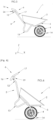
- FIG. 1 representing an example of a wheelbarrow 1 comprising several sub-assembly, namely a container 2, two stretchers 3, a wheel 4, a chassis 5, as well as a gripping system 6 .
- the container 2 is secured to the frame, and the frame is secured to the stretchers 3.
- the wheel 4 is pivotally mounted on the stretchers 3, which makes it possible to roll the wheelbarrow 1, and to transport a load, for example materials (earth, rubble, sand) or tools to a destination site.
- a load for example materials (earth, rubble, sand) or tools to a destination site.
- the gripping system 6 is advantageously pivotally mounted on the stretchers 3, the gripping system 6 moving between a transport position, allowing the wheelbarrow 1 to be moved by gripping the gripping system 6 , and a dumping position, facilitating dumping of the load carried.
- wheelbarrow 1 is in loading configuration.
- the wheelbarrow 1 rests on the ground (not shown on the figure 1 ), the stretchers 3 and the wheel 4 each offering points of contact with the ground, so as to be in balance.
- the wheelbarrow 1 is not lifted by the user, and the container 2 can receive a load.
- wheelbarrow 1 is in rolling configuration.
- the user (not shown) lifts the wheelbarrow 1 via the gripping system 6 , so that the wheelbarrow defines an angle relative to the ground.
- the gripping system 6 in the transport position, allows a grip identical to a grip of a wheelbarrow 1 not equipped with such a system.
- the wheelbarrow 1 can thus be moved from one point to another by rolling.
- the wheelbarrow 1 is shown on the Figure 6 in dumping configuration, the user rotates the wheelbarrow 1 defining an angle with the ground greater than in rolling configuration relative to the ground.
- the gripping system 6 pivots so as to position itself in the dumping position, in order to limit the bending of the user's wrist.
- the load located in the wheelbarrow 1 can thus exit the container 2 by sliding, and fall for example on the ground or any other receiving surface.
- the container 2 advantageously comprises a bottom 7, lateral sides 8 , a front side 9 and a rear side 10 , so as to give the container 2 the shape of a hopper provided with an opening 11 in order to allow filling, rolling and unloading (for example by pouring) a load in a secure manner.
- the container 2 is advantageously made of metallic material, for example steel or aluminum alloy, but in other embodiments, the container 2 is made of polymer or composite material, making it possible to reduce the weight of the wheelbarrow 1, this which is favorable regarding protection against MSDs.
- the container 2 is advantageously secured to the chassis 5 for example by means of securing means such as fixing screws or rivets.
- the container 2 is secured to the chassis by welding.
- the chassis 5 is used to allow the fixing of a wheel 4 and the container 2.
- the chassis 5 thus makes it possible to reinforce the bottom 7 and the front side 9 of the container 2.
- Wheel 4 can be a solid wheel, an inflated wheel or a puncture-proof wheel. Wheel 4 may include rims, in particular metal rims, or even a flange. The wheel 4 advantageously has ball or roller bearings, for comfort in use.
- the stretchers 3 advantageously comprise a free extreme part 12 close to the user, a foot part 13 , and a front part 14 allowing the fixing of the wheel 4.
- the free extreme part 12 extends in a direction opposite the ground when the wheelbarrow 1 is in loading and rolling configuration. This way, the user does not have to bend too far when lifting the wheelbarrow 1 when changing from the loading configuration to the rolling configuration.
- the wheelbarrow 1 has a plane of symmetry, passing in particular through the wheel 4 and the middle of the bottom 7, the front side 9 and the rear side 10 . In this way, the use of the wheelbarrow 1 is facilitated due to the balance resulting from such symmetry, which limits the risk of the appearance of MSDs.
- the gripping system 6 comprises a first handle 15 and a second handle 16, advantageously secured to each other, for example via a connecting means 17 .
- first handle 15 (respectively second handle 16) causes the movement of the second handle 16 (respectively first handle 15), which makes it possible to simplify the movement of the handles from one position to another.
- the pivoting of the handles 15, 16 is also avoided, making it possible to maintain the maneuverability of the wheelbarrow 1.
- the handles 15, 16 are joined together via a connecting means 17 extending substantially transversely, so that the handles 15, 16 and the connecting means 17 form a one-piece structure.
- a connecting means 17 extending substantially transversely, so that the handles 15, 16 and the connecting means 17 form a one-piece structure.
- Such a structure offers robustness allowing it to withstand the forces exerted by the loaded wheelbarrow 1 .
- such a structure allows the gripping system 6 to have no impact on the handling of the wheelbarrow 1 in rolling configuration, in particular for rolling around bends.
- Each of the handles 15, 16 advantageously comprises a gripping means 18 , allowing in particular the gripping of the gripping system 6 , and a fixing means 19 extending projecting from the gripping means 18 , the fixing means 19 making it possible to connect the gripping system 6 to the stretchers 3.
- the gripping means 18 comprises for example a segment 20 of input and a connecting segment 21 .
- the gripping segment 20 allows the gripping system 6 to be gripped by the user's hand, the connecting segment making it possible to connect one of the handles 15, 16 to the connecting means 17 .
- the gripping segment 20 advantageously extends parallel to the free end part 12 of the stretcher 3, when the gripping system 6 is in the transport position. In this way, when the wheelbarrow 1 is in loading configuration or in rolling configuration, the grip segment 20 offers a grip identical to the grip that would be offered by stretchers mounted on a conventional wheelbarrow, that is to say not equipped with a 6 gripping system. The user's habits are therefore not modified by the use of a wheelbarrow equipped with the gripping system 6 .
- the gripping segment 20 is advantageously covered with a tip 22, for example made of polymer material (PVC, synthetic rubber), in order to give the user the most pleasant feeling possible during the gripping action of the means 18 gripping, and to facilitate the handling of the gripping system 6 .
- a tip 22 for example made of polymer material (PVC, synthetic rubber), in order to give the user the most pleasant feeling possible during the gripping action of the means 18 gripping, and to facilitate the handling of the gripping system 6 .
- the fixing means 19 is advantageously provided with an orifice 23 allowing the insertion of an axis 24 passing through a hole 25 made on the extreme part 12 of a stretcher 3. In this way, we obtain a pivot connection between the gripping system 6 and the stretchers 3. The user can thus put the gripping system 6 in the transport or dumping position.
- the pivot connection is formed on a free end part 12 of the stretchers 3, for example near an edge 26.
- the pivot connection is located under the gripping segment 20 , making it possible to avoid having to excessive effort on the wrists when dumping the wheelbarrow 1, improving the ergonomics of the wheelbarrow 1.
- the passage of the gripping system 6 from the transport position to the dumping position can then be carried out by pivoting in a trigonometric direction, in other words downwards when the wheelbarrow 1 is in rolling or loading configuration.
- Such a provision is advantageous when the gripping system 6 is in spill configuration, because the gripping segment 20 can be positioned in an ergonomic position for the user.
- the fixing means 19 comprises a proximal portion 27 and a distal portion 28 , the distal portion 28 projecting from the proximal portion 27 .
- the proximal portion 27 advantageously projects from the connecting segment 21 .
- the proximal portion 27 extends towards the ground, and the distal portion 28 extends parallel to the gripping segment 20 . In this way, when the gripping system 6 is in the transport position, the gripping segment 20 extends in a substantially horizontal direction, making it easier to grip the wheelbarrow 1.
- the fixing means 19 each have the shape of a plate, that is to say they have a transverse dimension that is much smaller than the vertical or longitudinal dimensions.
- the fixing means 19 having an external surface 29 and an internal surface 30 , both parallel to a longitudinal plane.
- the internal surfaces 30 of the fixing means 19 face each other.
- the external surfaces 29 are integrally fixed to the connecting segment 21 , for example by welding.
- the gripping means 18 can thus come into abutment against the stretchers, when a rotation in the opposite direction to the trigonometric direction is applied.
- a lifting force exerted by the user has the effect of blocking the movement of the gripping system 6 , when a user lifts the wheelbarrow 1 via the handles 15, 16.
- the connecting means 17 comprises a first curved section 31 , a second curved section 32 , and a rectilinear section 33 disposed between the first curved section 31 and the second curved section 32 .
- the first curved section 31 is for example secured to the means 18 for gripping the first handle
- the second curved section 32 is secured to the means for gripping the second handle 16
- the first curved section 31 and the second curved section 32 extending in the same direction, so that the connecting means 17 and the gripping means 18 together have a substantially curved shape, for example U-shaped, or horseshoe-shaped.
- the connecting means 17 is arranged directly on the gripping means 18, the rectilinear section 33 is arranged at the height of the wrists of a user.
- the gripping means 18 does not hinder the user's movements, and does not interfere with the user's legs.
- the fixing means 19 , the stretchers 3, the connecting means 17 are formed from a profiled tubular section and have an identical diameter, allowing in particular easier manufacturing.
- the wheelbarrow 1, equipped with the gripping system 6 is intended to be sold assembled, the user being able to use it immediately after purchase.
- the wheelbarrow 1 is sold in individual parts (sale in kits), the end user being responsible for assembling all the parts.
- the wheelbarrow 1 thus has compact packaging, which is, for example, favorable for transport and storage.
- the user grasps the gripping segments 20 of the handles 15, 16 and exerts an effort upwards, away from the ground.
- Such an effort causes a pivoting of the gripping system 6 , which abuts against the stretchers 3.
- the continuation of the effort causes the lifting of the foot part 13 of the stretchers 3, the wheelbarrow 1 being in a rolling configuration , as shown Figure 5 and able to be moved.
- the user When the user wishes to empty the container 2, he simply needs to exert an effort comprising a vertical and longitudinal component. Concretely, the user exerts an effort by simultaneously lifting and pulling the gripping system. Such an action has the effect of rotating the gripping system 6 in a trigonometric direction, which allows the user to limit the flexion of his wrists. As a result, the user's wrists undergo limited effort, which helps to reduce the risk of developing MSDs.
- the gripping system 6 and the wheelbarrow 1 equipped with such a gripping system, find advantageous applications in the field of construction, public works, agricultural and landscaping work, whether for use in a professional setting , or personal.
Landscapes
- Engineering & Computer Science (AREA)
- Chemical & Material Sciences (AREA)
- Combustion & Propulsion (AREA)
- Transportation (AREA)
- Mechanical Engineering (AREA)
- Handcart (AREA)
Claims (8)
- Schubkarre, umfassend:- einen Rahmen (5) mit einem Paar Holme (3),- ein Rad (4),- einen Behälter (2),- wobei jeder Holm (3) einen freien äußersten Teil (12), einen Fußteil (13) und einen vorderen Teil (14) zur Befestigung des Rades (4) umfasst,- ein auf den Holmen (3) drehbar angebrachtes Greifsystem (6), wobei das Greifsystem (6) geeignet ist, zwischen einer Transportposition und einer Auskippposition zu wechseln, wobei das Greifsystem (6) einen ersten Griff (15) und einen zweiten Griff (16) umfasst, wobei jeder der Griffe (15, 16) umfasst:- ein Greifmittel (18), das ein Greifsegment (20) umfasst, das das Ergreifen des Greifsystems (6) mit der Hand des Benutzers ermöglicht,- ein Befestigungsmittel (19), das sich ab dem Greifmittel (18) hervorragend erstreckt, wobei das Befestigungsmittel (19) in Drehverbindung an einem Holm (3) angebracht ist, wobei die Griffe (15,16) fest miteinander verbunden sind,- dadurch gekennzeichnet, dass sich das Greifsegment (20) jedes Greifmittels (18) parallel zum freien äußersten Teil (12) eines Holms (3) erstreckt, wenn sich das Greifsystem (6) in Transportposition befindet.
- Schubkarre nach vorhergehendem Anspruch, dadurch gekennzeichnet, dass die Griffe (15,16) durch ein sich im Wesentlichen quererstreckendes Verbindungsmittel (17) miteinander verbunden sind, so dass mit den Griffen (15, 16) eine einteilige Struktur gebildet wird.
- Schubkarre nach Anspruch 1 oder 2, dadurch gekennzeichnet, dass das Befestigungsmittel (19) einen proximalen Abschnitt (27) und einen freien distalen Abschnitt (28) umfasst, wobei das Greifmittel (18) das Greifsegment (20) und ein Verbindungssegment (21) umfasst, wobei sich der freie distale Abschnitt (28) ab dem Verbindungssegment (21) erstreckt, indem er sich parallel zum Greifsegment (20) erstreckt.
- Schubkarre nach Anspruch 2, dadurch gekennzeichnet, dass das Verbindungsmittel (17) einen ersten gekrümmten Abschnitt (31), einen zweiten gekrümmten Abschnitt (32) und einen geraden Abschnitt (33) umfasst, der zwischen dem ersten gekrümmten Abschnitt (31) und dem zweiten gekrümmten Abschnitt (32) angeordnet ist, wobei der erste gekrümmte Abschnitt (31) fest mit dem Griffmittel (18) des ersten Griffs (15) verbunden ist, wobei der zweite gekrümmte Abschnitt (32) fest mit dem Greifmittel (18) des zweiten Griffs (16) verbunden ist, wobei sich der erste gekrümmte Abschnitt (31) und der zweite gekrümmte Abschnitt (32) in dieselbe Richtung erstrecken, sodass das Verbindungsmittel (17) und die Greifmittel (18) zusammen eine im Wesentlichen gekrümmte Form aufweisen.
- Schubkarre nach einem der vorhergehenden Ansprüche, dadurch gekennzeichnet, dass ein innerer Raum zwischen dem Greifmittel (18) des ersten Griffs (15) und dem Greifmittel (18) des zweiten Griffs (16) definiert ist, wobei die Befestigungsmittel (19) aus jedem Greifmittel (18) innerhalb des inneren Raums herausragen, sodass, wenn sich das Greifsystem (6) in Transportstellung befindet, das Greifsystem (6) einen Holm (3) berührt.
- Schubkarre nach Anspruch 5, dadurch gekennzeichnet, dass das Befestigungsmittel (19) am äußersten Teil (12) drehbar montiert ist.
- Schubkarre nach vorhergehendem Anspruch, dadurch gekennzeichnet, dass der Abstand in Querrichtung zwischen dem Befestigungsmittel (19) des ersten Griffs (15) und dem Befestigungsmittel (19) des zweiten Griffs (16) gleich dem Abstand in Querrichtung zwischen den beiden Holmen (3) ist.
- Schubkarre nach einem der vorhergehenden Ansprüche, dadurch gekennzeichnet, dass das Befestigungsmittel (19), die Holme (3) und das Verbindungsmittel (17) aus Rohrprofilabschnitten mit identischem Durchmesser gebildet sind.
Applications Claiming Priority (1)
| Application Number | Priority Date | Filing Date | Title |
|---|---|---|---|
| FR1910200A FR3100787B1 (fr) | 2019-09-16 | 2019-09-16 | Systeme de prehension pivotant et brouette equipee d'un tel systeme de prehension |
Publications (2)
| Publication Number | Publication Date |
|---|---|
| EP3792144A1 EP3792144A1 (de) | 2021-03-17 |
| EP3792144B1 true EP3792144B1 (de) | 2024-06-12 |
Family
ID=69024376
Family Applications (1)
| Application Number | Title | Priority Date | Filing Date |
|---|---|---|---|
| EP20193214.2A Active EP3792144B1 (de) | 2019-09-16 | 2020-08-27 | Schubkarre ausgestattet mit einem schwenkbaren greifsystem |
Country Status (2)
| Country | Link |
|---|---|
| EP (1) | EP3792144B1 (de) |
| FR (1) | FR3100787B1 (de) |
Family Cites Families (6)
| Publication number | Priority date | Publication date | Assignee | Title |
|---|---|---|---|---|
| US5153966A (en) | 1991-07-11 | 1992-10-13 | Godwin Marvin C | Lifting handle attachment for wheelbarrows |
| US5799960A (en) | 1995-10-27 | 1998-09-01 | Davis, Sr.; Eddie Charles | Rotating safety handles for wheelbarrows |
| US5794307A (en) * | 1996-11-04 | 1998-08-18 | Overcash; Rufus B. | Wheelbarrow handle extension |
| WO2011140207A1 (en) * | 2010-05-04 | 2011-11-10 | Kilen Scott R | Wheelbarrow |
| DE102014002237B4 (de) * | 2014-02-20 | 2019-12-19 | Klaus Martens | Zusammenlegbare Schubkarre |
| US20170113709A1 (en) * | 2015-10-22 | 2017-04-27 | Mason Target Systems, Llc | Clipable modular carts for transporting devices and methods of use |
-
2019
- 2019-09-16 FR FR1910200A patent/FR3100787B1/fr active Active
-
2020
- 2020-08-27 EP EP20193214.2A patent/EP3792144B1/de active Active
Also Published As
| Publication number | Publication date |
|---|---|
| FR3100787B1 (fr) | 2023-01-06 |
| FR3100787A1 (fr) | 2021-03-19 |
| EP3792144A1 (de) | 2021-03-17 |
Similar Documents
| Publication | Publication Date | Title |
|---|---|---|
| FR2887219A3 (fr) | Bicyclette electrique pliante | |
| MXPA05007680A (es) | Carretilla de descarga facil. | |
| EP0252851A1 (de) | Zusammenlegbarer Handwagen, bestimmt für z.B. den Transport von Taschen für Golfclubs | |
| FR3095608A1 (fr) | Dispositif d’assistance physique non robotisé/non motorisé de type exosquelette pour le transport manuel de charges | |
| FR2980449A1 (fr) | Cadre de bicyclette | |
| EP1600134A1 (de) | Aufrichtstuhl mit Aufrichtoperationsuntersetzung | |
| WO2013057510A1 (en) | Attachment device and method of use thereof | |
| FR3065387A1 (fr) | Exosquelette a energie passive et collaboratif | |
| FR2467127A1 (fr) | Perfectionnements a des poussettes de bebe | |
| EP3792144A1 (de) | Schwenkbares greifsystem und schubkarre, die mit einem solchen greifsystem ausgestattet ist | |
| EP2483140B1 (de) | In ein einkaufswagen umwandelbares klapprad | |
| EP2029082A1 (de) | Gehhilfe | |
| FR2969949A1 (fr) | Structure roulante, pour outil a bras connecte a un bloc aspirateur, incluant un dispositif de basculement | |
| FR3053302A1 (fr) | Chariot de manutention motorise | |
| US20110272650A1 (en) | Lifting and Moving Device | |
| EP2893912B1 (de) | MEDIZINISCHER ROLLSTUHL MIT GELENK-FUßSTÜTZE | |
| FR2993237A1 (fr) | Moyen de pliage verrouillage adapte a un vehicule terrestre ayant des elements de structure tubulaire | |
| EP3792143B1 (de) | Schubkarre, die mit einer schwenkbaren greifanordnung ausgestattet ist | |
| BE1009456A6 (fr) | Bagage a main. | |
| EP3383592B1 (de) | Exoskelett zur unterstützung horizontaler versuche | |
| CH717704A1 (fr) | Dispositif d'aide aux personnes à mobilité réduite. | |
| FR2545405A1 (fr) | Dispositif support elevateur pour vehicule a deux roues | |
| FR3107499A1 (fr) | Dispositif de manutention d’un élément au sol de type glissière de sécurité | |
| FR2897037A1 (fr) | Chariot de transport pliable tout terrain et son sac | |
| EP0096633B1 (de) | Kombination von zylindricalem Fass und Karren zum Aufrichten |
Legal Events
| Date | Code | Title | Description |
|---|---|---|---|
| PUAI | Public reference made under article 153(3) epc to a published international application that has entered the european phase |
Free format text: ORIGINAL CODE: 0009012 |
|
| STAA | Information on the status of an ep patent application or granted ep patent |
Free format text: STATUS: THE APPLICATION HAS BEEN PUBLISHED |
|
| AK | Designated contracting states |
Kind code of ref document: A1 Designated state(s): AL AT BE BG CH CY CZ DE DK EE ES FI FR GB GR HR HU IE IS IT LI LT LU LV MC MK MT NL NO PL PT RO RS SE SI SK SM TR |
|
| AX | Request for extension of the european patent |
Extension state: BA ME |
|
| STAA | Information on the status of an ep patent application or granted ep patent |
Free format text: STATUS: REQUEST FOR EXAMINATION WAS MADE |
|
| 17P | Request for examination filed |
Effective date: 20210628 |
|
| RBV | Designated contracting states (corrected) |
Designated state(s): AL AT BE BG CH CY CZ DE DK EE ES FI FR GB GR HR HU IE IS IT LI LT LU LV MC MK MT NL NO PL PT RO RS SE SI SK SM TR |
|
| STAA | Information on the status of an ep patent application or granted ep patent |
Free format text: STATUS: EXAMINATION IS IN PROGRESS |
|
| 17Q | First examination report despatched |
Effective date: 20221026 |
|
| GRAP | Despatch of communication of intention to grant a patent |
Free format text: ORIGINAL CODE: EPIDOSNIGR1 |
|
| STAA | Information on the status of an ep patent application or granted ep patent |
Free format text: STATUS: GRANT OF PATENT IS INTENDED |
|
| INTG | Intention to grant announced |
Effective date: 20240221 |
|
| RIN1 | Information on inventor provided before grant (corrected) |
Inventor name: ESTEVE, CHRISTOPHE |
|
| GRAS | Grant fee paid |
Free format text: ORIGINAL CODE: EPIDOSNIGR3 |
|
| GRAA | (expected) grant |
Free format text: ORIGINAL CODE: 0009210 |
|
| STAA | Information on the status of an ep patent application or granted ep patent |
Free format text: STATUS: THE PATENT HAS BEEN GRANTED |
|
| AK | Designated contracting states |
Kind code of ref document: B1 Designated state(s): AL AT BE BG CH CY CZ DE DK EE ES FI FR GB GR HR HU IE IS IT LI LT LU LV MC MK MT NL NO PL PT RO RS SE SI SK SM TR |
|
| REG | Reference to a national code |
Ref country code: GB Ref legal event code: FG4D Free format text: NOT ENGLISH |
|
| REG | Reference to a national code |
Ref country code: CH Ref legal event code: EP |
|
| REG | Reference to a national code |
Ref country code: DE Ref legal event code: R096 Ref document number: 602020032213 Country of ref document: DE |
|
| REG | Reference to a national code |
Ref country code: IE Ref legal event code: FG4D Free format text: LANGUAGE OF EP DOCUMENT: FRENCH |
|
| PG25 | Lapsed in a contracting state [announced via postgrant information from national office to epo] |
Ref country code: BG Free format text: LAPSE BECAUSE OF FAILURE TO SUBMIT A TRANSLATION OF THE DESCRIPTION OR TO PAY THE FEE WITHIN THE PRESCRIBED TIME-LIMIT Effective date: 20240612 |
|
| PG25 | Lapsed in a contracting state [announced via postgrant information from national office to epo] |
Ref country code: FI Free format text: LAPSE BECAUSE OF FAILURE TO SUBMIT A TRANSLATION OF THE DESCRIPTION OR TO PAY THE FEE WITHIN THE PRESCRIBED TIME-LIMIT Effective date: 20240612 Ref country code: HR Free format text: LAPSE BECAUSE OF FAILURE TO SUBMIT A TRANSLATION OF THE DESCRIPTION OR TO PAY THE FEE WITHIN THE PRESCRIBED TIME-LIMIT Effective date: 20240612 |
|
| REG | Reference to a national code |
Ref country code: LT Ref legal event code: MG9D |
|
| PG25 | Lapsed in a contracting state [announced via postgrant information from national office to epo] |
Ref country code: GR Free format text: LAPSE BECAUSE OF FAILURE TO SUBMIT A TRANSLATION OF THE DESCRIPTION OR TO PAY THE FEE WITHIN THE PRESCRIBED TIME-LIMIT Effective date: 20240913 |
|
| REG | Reference to a national code |
Ref country code: NL Ref legal event code: MP Effective date: 20240612 |
|
| PG25 | Lapsed in a contracting state [announced via postgrant information from national office to epo] |
Ref country code: ES Free format text: LAPSE BECAUSE OF FAILURE TO SUBMIT A TRANSLATION OF THE DESCRIPTION OR TO PAY THE FEE WITHIN THE PRESCRIBED TIME-LIMIT Effective date: 20240612 |
|
| PG25 | Lapsed in a contracting state [announced via postgrant information from national office to epo] |
Ref country code: LV Free format text: LAPSE BECAUSE OF FAILURE TO SUBMIT A TRANSLATION OF THE DESCRIPTION OR TO PAY THE FEE WITHIN THE PRESCRIBED TIME-LIMIT Effective date: 20240612 |
|
| PG25 | Lapsed in a contracting state [announced via postgrant information from national office to epo] |
Ref country code: NO Free format text: LAPSE BECAUSE OF FAILURE TO SUBMIT A TRANSLATION OF THE DESCRIPTION OR TO PAY THE FEE WITHIN THE PRESCRIBED TIME-LIMIT Effective date: 20240912 Ref country code: LV Free format text: LAPSE BECAUSE OF FAILURE TO SUBMIT A TRANSLATION OF THE DESCRIPTION OR TO PAY THE FEE WITHIN THE PRESCRIBED TIME-LIMIT Effective date: 20240612 Ref country code: HR Free format text: LAPSE BECAUSE OF FAILURE TO SUBMIT A TRANSLATION OF THE DESCRIPTION OR TO PAY THE FEE WITHIN THE PRESCRIBED TIME-LIMIT Effective date: 20240612 Ref country code: GR Free format text: LAPSE BECAUSE OF FAILURE TO SUBMIT A TRANSLATION OF THE DESCRIPTION OR TO PAY THE FEE WITHIN THE PRESCRIBED TIME-LIMIT Effective date: 20240913 Ref country code: FI Free format text: LAPSE BECAUSE OF FAILURE TO SUBMIT A TRANSLATION OF THE DESCRIPTION OR TO PAY THE FEE WITHIN THE PRESCRIBED TIME-LIMIT Effective date: 20240612 Ref country code: ES Free format text: LAPSE BECAUSE OF FAILURE TO SUBMIT A TRANSLATION OF THE DESCRIPTION OR TO PAY THE FEE WITHIN THE PRESCRIBED TIME-LIMIT Effective date: 20240612 Ref country code: BG Free format text: LAPSE BECAUSE OF FAILURE TO SUBMIT A TRANSLATION OF THE DESCRIPTION OR TO PAY THE FEE WITHIN THE PRESCRIBED TIME-LIMIT Effective date: 20240612 Ref country code: RS Free format text: LAPSE BECAUSE OF FAILURE TO SUBMIT A TRANSLATION OF THE DESCRIPTION OR TO PAY THE FEE WITHIN THE PRESCRIBED TIME-LIMIT Effective date: 20240912 |
|
| PG25 | Lapsed in a contracting state [announced via postgrant information from national office to epo] |
Ref country code: NL Free format text: LAPSE BECAUSE OF FAILURE TO SUBMIT A TRANSLATION OF THE DESCRIPTION OR TO PAY THE FEE WITHIN THE PRESCRIBED TIME-LIMIT Effective date: 20240612 |
|
| REG | Reference to a national code |
Ref country code: AT Ref legal event code: MK05 Ref document number: 1694009 Country of ref document: AT Kind code of ref document: T Effective date: 20240612 |
|
| PG25 | Lapsed in a contracting state [announced via postgrant information from national office to epo] |
Ref country code: NL Free format text: LAPSE BECAUSE OF FAILURE TO SUBMIT A TRANSLATION OF THE DESCRIPTION OR TO PAY THE FEE WITHIN THE PRESCRIBED TIME-LIMIT Effective date: 20240612 |
|
| PG25 | Lapsed in a contracting state [announced via postgrant information from national office to epo] |
Ref country code: PT Free format text: LAPSE BECAUSE OF FAILURE TO SUBMIT A TRANSLATION OF THE DESCRIPTION OR TO PAY THE FEE WITHIN THE PRESCRIBED TIME-LIMIT Effective date: 20241014 |
|
| PG25 | Lapsed in a contracting state [announced via postgrant information from national office to epo] |
Ref country code: PT Free format text: LAPSE BECAUSE OF FAILURE TO SUBMIT A TRANSLATION OF THE DESCRIPTION OR TO PAY THE FEE WITHIN THE PRESCRIBED TIME-LIMIT Effective date: 20241014 |
|
| PG25 | Lapsed in a contracting state [announced via postgrant information from national office to epo] |
Ref country code: PL Free format text: LAPSE BECAUSE OF FAILURE TO SUBMIT A TRANSLATION OF THE DESCRIPTION OR TO PAY THE FEE WITHIN THE PRESCRIBED TIME-LIMIT Effective date: 20240612 |
|
| PG25 | Lapsed in a contracting state [announced via postgrant information from national office to epo] |
Ref country code: EE Free format text: LAPSE BECAUSE OF FAILURE TO SUBMIT A TRANSLATION OF THE DESCRIPTION OR TO PAY THE FEE WITHIN THE PRESCRIBED TIME-LIMIT Effective date: 20240612 |
|
| PG25 | Lapsed in a contracting state [announced via postgrant information from national office to epo] |
Ref country code: AT Free format text: LAPSE BECAUSE OF FAILURE TO SUBMIT A TRANSLATION OF THE DESCRIPTION OR TO PAY THE FEE WITHIN THE PRESCRIBED TIME-LIMIT Effective date: 20240612 Ref country code: IS Free format text: LAPSE BECAUSE OF FAILURE TO SUBMIT A TRANSLATION OF THE DESCRIPTION OR TO PAY THE FEE WITHIN THE PRESCRIBED TIME-LIMIT Effective date: 20241012 |
|
| PG25 | Lapsed in a contracting state [announced via postgrant information from national office to epo] |
Ref country code: CZ Free format text: LAPSE BECAUSE OF FAILURE TO SUBMIT A TRANSLATION OF THE DESCRIPTION OR TO PAY THE FEE WITHIN THE PRESCRIBED TIME-LIMIT Effective date: 20240612 |
|
| PG25 | Lapsed in a contracting state [announced via postgrant information from national office to epo] |
Ref country code: RO Free format text: LAPSE BECAUSE OF FAILURE TO SUBMIT A TRANSLATION OF THE DESCRIPTION OR TO PAY THE FEE WITHIN THE PRESCRIBED TIME-LIMIT Effective date: 20240612 Ref country code: SK Free format text: LAPSE BECAUSE OF FAILURE TO SUBMIT A TRANSLATION OF THE DESCRIPTION OR TO PAY THE FEE WITHIN THE PRESCRIBED TIME-LIMIT Effective date: 20240612 |
|
| PG25 | Lapsed in a contracting state [announced via postgrant information from national office to epo] |
Ref country code: SM Free format text: LAPSE BECAUSE OF FAILURE TO SUBMIT A TRANSLATION OF THE DESCRIPTION OR TO PAY THE FEE WITHIN THE PRESCRIBED TIME-LIMIT Effective date: 20240612 |
|
| PG25 | Lapsed in a contracting state [announced via postgrant information from national office to epo] |
Ref country code: SM Free format text: LAPSE BECAUSE OF FAILURE TO SUBMIT A TRANSLATION OF THE DESCRIPTION OR TO PAY THE FEE WITHIN THE PRESCRIBED TIME-LIMIT Effective date: 20240612 Ref country code: SK Free format text: LAPSE BECAUSE OF FAILURE TO SUBMIT A TRANSLATION OF THE DESCRIPTION OR TO PAY THE FEE WITHIN THE PRESCRIBED TIME-LIMIT Effective date: 20240612 Ref country code: RO Free format text: LAPSE BECAUSE OF FAILURE TO SUBMIT A TRANSLATION OF THE DESCRIPTION OR TO PAY THE FEE WITHIN THE PRESCRIBED TIME-LIMIT Effective date: 20240612 Ref country code: PL Free format text: LAPSE BECAUSE OF FAILURE TO SUBMIT A TRANSLATION OF THE DESCRIPTION OR TO PAY THE FEE WITHIN THE PRESCRIBED TIME-LIMIT Effective date: 20240612 Ref country code: IS Free format text: LAPSE BECAUSE OF FAILURE TO SUBMIT A TRANSLATION OF THE DESCRIPTION OR TO PAY THE FEE WITHIN THE PRESCRIBED TIME-LIMIT Effective date: 20241012 Ref country code: EE Free format text: LAPSE BECAUSE OF FAILURE TO SUBMIT A TRANSLATION OF THE DESCRIPTION OR TO PAY THE FEE WITHIN THE PRESCRIBED TIME-LIMIT Effective date: 20240612 Ref country code: CZ Free format text: LAPSE BECAUSE OF FAILURE TO SUBMIT A TRANSLATION OF THE DESCRIPTION OR TO PAY THE FEE WITHIN THE PRESCRIBED TIME-LIMIT Effective date: 20240612 Ref country code: AT Free format text: LAPSE BECAUSE OF FAILURE TO SUBMIT A TRANSLATION OF THE DESCRIPTION OR TO PAY THE FEE WITHIN THE PRESCRIBED TIME-LIMIT Effective date: 20240612 |
|
| PG25 | Lapsed in a contracting state [announced via postgrant information from national office to epo] |
Ref country code: IT Free format text: LAPSE BECAUSE OF FAILURE TO SUBMIT A TRANSLATION OF THE DESCRIPTION OR TO PAY THE FEE WITHIN THE PRESCRIBED TIME-LIMIT Effective date: 20240612 |
|
| REG | Reference to a national code |
Ref country code: DE Ref legal event code: R097 Ref document number: 602020032213 Country of ref document: DE |
|
| REG | Reference to a national code |
Ref country code: CH Ref legal event code: PL |
|
| PG25 | Lapsed in a contracting state [announced via postgrant information from national office to epo] |
Ref country code: DK Free format text: LAPSE BECAUSE OF FAILURE TO SUBMIT A TRANSLATION OF THE DESCRIPTION OR TO PAY THE FEE WITHIN THE PRESCRIBED TIME-LIMIT Effective date: 20240612 |
|
| PG25 | Lapsed in a contracting state [announced via postgrant information from national office to epo] |
Ref country code: LU Free format text: LAPSE BECAUSE OF NON-PAYMENT OF DUE FEES Effective date: 20240827 |
|
| PLBE | No opposition filed within time limit |
Free format text: ORIGINAL CODE: 0009261 |
|
| STAA | Information on the status of an ep patent application or granted ep patent |
Free format text: STATUS: NO OPPOSITION FILED WITHIN TIME LIMIT |
|
| PG25 | Lapsed in a contracting state [announced via postgrant information from national office to epo] |
Ref country code: MC Free format text: LAPSE BECAUSE OF FAILURE TO SUBMIT A TRANSLATION OF THE DESCRIPTION OR TO PAY THE FEE WITHIN THE PRESCRIBED TIME-LIMIT Effective date: 20240612 Ref country code: CH Free format text: LAPSE BECAUSE OF NON-PAYMENT OF DUE FEES Effective date: 20240831 |
|
| 26N | No opposition filed |
Effective date: 20250313 |
|
| GBPC | Gb: european patent ceased through non-payment of renewal fee |
Effective date: 20240912 |
|
| REG | Reference to a national code |
Ref country code: BE Ref legal event code: MM Effective date: 20240831 |
|
| PG25 | Lapsed in a contracting state [announced via postgrant information from national office to epo] |
Ref country code: GB Free format text: LAPSE BECAUSE OF NON-PAYMENT OF DUE FEES Effective date: 20240912 |
|
| PG25 | Lapsed in a contracting state [announced via postgrant information from national office to epo] |
Ref country code: BE Free format text: LAPSE BECAUSE OF NON-PAYMENT OF DUE FEES Effective date: 20240831 |
|
| REG | Reference to a national code |
Ref country code: DE Ref legal event code: R081 Ref document number: 602020032213 Country of ref document: DE Owner name: HAEMMERLIN, FR Free format text: FORMER OWNER: CDH GROUP, ROMILLY SUR ANDELLE, FR |
|
| PG25 | Lapsed in a contracting state [announced via postgrant information from national office to epo] |
Ref country code: IE Free format text: LAPSE BECAUSE OF NON-PAYMENT OF DUE FEES Effective date: 20240827 |
|
| PG25 | Lapsed in a contracting state [announced via postgrant information from national office to epo] |
Ref country code: SE Free format text: LAPSE BECAUSE OF FAILURE TO SUBMIT A TRANSLATION OF THE DESCRIPTION OR TO PAY THE FEE WITHIN THE PRESCRIBED TIME-LIMIT Effective date: 20240612 |
|
| PGFP | Annual fee paid to national office [announced via postgrant information from national office to epo] |
Ref country code: DE Payment date: 20250724 Year of fee payment: 6 |
|
| PGFP | Annual fee paid to national office [announced via postgrant information from national office to epo] |
Ref country code: FR Payment date: 20250804 Year of fee payment: 6 |
|
| PG25 | Lapsed in a contracting state [announced via postgrant information from national office to epo] |
Ref country code: CY Free format text: LAPSE BECAUSE OF FAILURE TO SUBMIT A TRANSLATION OF THE DESCRIPTION OR TO PAY THE FEE WITHIN THE PRESCRIBED TIME-LIMIT; INVALID AB INITIO Effective date: 20200827 |
|
| PG25 | Lapsed in a contracting state [announced via postgrant information from national office to epo] |
Ref country code: HU Free format text: LAPSE BECAUSE OF FAILURE TO SUBMIT A TRANSLATION OF THE DESCRIPTION OR TO PAY THE FEE WITHIN THE PRESCRIBED TIME-LIMIT; INVALID AB INITIO Effective date: 20200827 |