EP3383592B1 - Exoskelett zur unterstützung horizontaler versuche - Google Patents
Exoskelett zur unterstützung horizontaler versuche Download PDFInfo
- Publication number
- EP3383592B1 EP3383592B1 EP16813093.8A EP16813093A EP3383592B1 EP 3383592 B1 EP3383592 B1 EP 3383592B1 EP 16813093 A EP16813093 A EP 16813093A EP 3383592 B1 EP3383592 B1 EP 3383592B1
- Authority
- EP
- European Patent Office
- Prior art keywords
- connecting member
- arm
- legs
- user
- axis
- Prior art date
- Legal status (The legal status is an assumption and is not a legal conclusion. Google has not performed a legal analysis and makes no representation as to the accuracy of the status listed.)
- Active
Links
Images


Classifications
-
- B—PERFORMING OPERATIONS; TRANSPORTING
- B25—HAND TOOLS; PORTABLE POWER-DRIVEN TOOLS; MANIPULATORS
- B25J—MANIPULATORS; CHAMBERS PROVIDED WITH MANIPULATION DEVICES
- B25J9/00—Program-controlled manipulators
- B25J9/0006—Exoskeletons, i.e. resembling a human figure
Definitions
- the present invention relates to the field of robotics and more particularly robots capable of collaborating with an operator, commonly designated by the term “cobot” or exoskeleton.
- the invention relates to a device of the exoskeleton type intended to assist the horizontal forces of a valid operator.
- It also relates to a method of using such a device.
- This device of the exoskeleton type comprises two legs arranged to be coupled to the feet of a user, a connecting member between the upper ends of the legs to which it is articulated, as well as a tool-carrying arm connected to the connecting member.
- This device can in particular be used with tools generating great strenuousness, in particular due to the significant horizontal forces to be provided at the level of the tool itself.
- the invention can thus be used advantageously in the construction and public works sectors and in any other type of industry requiring the use of tools and therefore assistance in the work of these tools, such as rakes or else any tool whose handling generates significant horizontal forces, such as perforators for vertical walls.
- the device according to the invention will thus be advantageously used by an operator who, in the context of a road construction site for example, produces coatings in products which require spreading, such as coated materials.
- the realization of the coating requires repetitive gestures over long periods, these gestures causing a torsion of the operator's trunk, as well as a strong stress on the shoulder and back.
- exoskeletons for using tools, to increase the physical capacities of a user.
- Some of them are very sophisticated, including systems actuation of the lower limbs, associated with direction sensors and calculation means.
- the object of the present invention is therefore to provide a device of the exoskeleton type and a method of using such a device making it possible to provide effective assistance to the horizontal efforts of an operator, while being robust and of reasonable cost .
- the invention proposes in particular a device of the exoskeleton type comprising two legs arranged to be coupled to the feet of a user, a connecting member between the upper ends of the legs to which it is articulated and a tool-carrying arm, connected to the liaison body, characterized in that the legs and the connecting member are arranged to substantially form a triangle, an apex of which belongs to the connecting member, so that all of the applied forces converge at the apex of said triangle.
- the device allows these forces to be transferred directly to the ground, without passing through the body of the operator whose weight is simply used to maintain balance.
- the body (back, arm) of the user provides less effort since the device allows actuation of the tool arm and therefore provides mechanical assistance to the user, and facilitates balance.
- the invention also provides a method of using a device of the exoskeleton type according to the invention, comprising two legs, a connecting member between the upper ends of the legs to which it is articulated and a tool-carrying arm connected to the connecting member, the legs and the connecting member being arranged to substantially form a triangle, an apex of which belongs to the connecting member, and said arm being slidably mounted on the and being provided actuation means controlled by means for detecting the intention of the user, such as a force sensor, a method according to which it is detected whether the user intends to exercise a force on the tool-carrying arm, thanks to said means for detecting the intention of the user and, when the detection is positive, said means for actuating the arm are controlled to ensure its movement in rectilinear translation, the direction of movement being identical to that detected by the detection means.
- the invention also relates to the use of the device as described above in parallel with the legs of another exoskeleton.
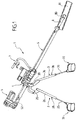
- figures 1 and 2 illustrate a device of the exoskeleton type according to an embodiment of the invention.
- This device 1 comprises two legs 2 and 3 and a connecting member 4 between the upper ends 20 and 30 of the legs, to which it is articulated.
- This triangle structure has the advantage of high rigidity for a given mass and size. It is therefore particularly robust.
- the legs 2 and 3 are connected to soles 22, 32, which comprise an actual sole 23, 33 and a stirrup 24, 34.
- the operator positions his feet on the soles 22 and 32.
- the undersides of the soles proper 23 and 33 are covered with a layer ensuring a good coefficient of adhesion between the sole and the ground. Indeed, this adhesion contributes to the balance of the operator and the device.
- the figures 6 to 8 show that the connecting member 4 is arranged to be positioned under the operator's pelvis, when the latter holds the device by the handles 6 and 7.
- connection means of harness type, between the connection member and the operator can be provided.
- This harness comprises a vest 90 worn by the operator and straps or elastic elements 91 intended to be connected to the connecting member 4.
- Each leg 2, 3 has two rods, a lower rod 25, 35 and an upper rod 26, 36, these two rods being slidably mounted relative to one another.
- the upper rods 26 and 36 have the shape of a tube whose diameter is greater than that of the lower rods 25 and 35, these lower rods being able to slide inside the upper rods 26 and 36.
- Blocking means 28, 38 for example formed by retractable blocking pins integral with one of the rods cooperating with orifices facing each other in the rod, are provided on the upper rods 26, 36 to fix the relative position of the lower rods and the upper rods. They are necessary to ensure the recovery of effort.
- the locking means are, in this embodiment, actuated manually.
- a ball joint 27, 37 connects a lower rod 25, 35 of a leg 2, 3 to a sole 22, 32.
- This ball joint is positioned to ensure the correct balance of the assembly constituted by the device and the operator, by eliminating the tilting effect of the foot and by promoting the support of the operator on a single foot.
- this ball joint can be positioned on the inside of the foot, about half of the heel and in height, for example over 100 mm.
- the device 1 comprises a tool-carrying arm 5 which here has the form of a tube. It is connected to the connecting member 4 so as to be inclined towards the ground, when the device is in use.
- the arm 5 On the side opposite to the handles 6 and 7, the arm 5 comprises a rod 8 which is mounted movable in rotation about the longitudinal axis Y of the arm.
- the rod 8 At one end 80, intended to be close to the ground, when the device is used, the rod 8 comprises a blade-type tool 81.
- the first handle 6 is fixed on the arm 5.
- this first handle is intended for gripping the device by an operator.
- this second handle 7 which is fixed to the connecting member 4 and which is therefore spaced from the first handle 6 by a non-zero distance.
- this second handle is located downstream of the connecting member 4 in the direction of inclination of the arm 5.
- the respective arrangement of the handles 6 and 7 on the arm 5 and on the connecting member 4 allows a user to return to the slotted position which he naturally adopts when handling a rake ( figure 6 ), but by correcting his posture to allow him to keep his back straight. All the applied forces are substantially in the same plane which is that of the triangle structure.
- the second handle 7 is mounted on a part 70, on which the connecting member is articulated, as will be described with reference to figures 3 and 4 .
- the arm 5 passes through this part 70 and is slidably mounted on this part 70 and therefore on the connecting member 4. Therefore, the distance between the two handles 6 and 7 can vary during the use of the device .
- actuation means 71 are controlled by means 72 for detecting the intention of the operator.
- These detection means 72 are for example in the form of a force sensor and they are provided at the level of the handle 6.
- Presence sensors 73 for example of the cell type in infrared beam mode, make it possible to ensure that the intention is voluntarily supplied by the hand of the operator.
- the actuating means 71 in particular supplied with electrical energy 74, thus make it possible to ensure the displacement in rectilinear translation of the arm 5, either in the direction of the ground, or in the direction of the operator, so as to assist the efforts of the operator, thanks to an amplification of its efforts, for example by a factor of 10.
- the force applied by the device to the tool can also be limited to prevent the risk of falling due to the forces which are not taken up by the structure and the operator, i.e. forces which do not belong to the plane defined by the triangle structure.
- This limitation is for example proportional to the weight of the operator or to the angular sweep of the rake around the Z axis.
- the rod 8 can rotate inside the arm 5, around its longitudinal axis Y (cf. figure 4 ). It is therefore movable in rotation relative to the connecting member 4. This rotation is obtained manually by the operator by acting on the first handle 6 through the transmission means 75. It could also be motorized. It makes it possible to make a turn of the rod and / or to adjust the orientation of the blade 81.
- the connecting member 4 makes it possible to ensure several degrees of freedom thanks to a double gimbal structure which is schematically illustrated in the figure 4 .
- This double gimbal comprises a first part 40, shown in the figure 4 in the form of two bent elements 400 and 401. These two elements are, in practice, a single piece.
- This universal joint comprises a second part 41 formed by two bent elements 410 and 411. They are represented in the form of two independent elements on the figure 4 but in practice constitute a unique piece.
- a first end of these elements 400 and 401 is connected to the part 70 in which the arm 5 is slidably mounted.
- Each of the bent elements 400 and 401 of the first part 40 are connected at their other end to a first end of the bent elements 410 and 411.
- the second end of these elements 410 and 411 is, for its part, connected to one end of other bent elements 28 and 38, the other end of which is fixed to one of the legs 2, 3.
- connection between the elements 400, 401 of the first part 40 and the elements 410 and 411 of the second part 41 is carried out by means of an articulation 42 allowing rotation around an axis Z.
- This axis Z passes between the two legs 2 and 3 and it is substantially vertical when the device is in use.
- these articulations 42 allow the arm 5 to rotate about the axis Z in order to achieve an angular scanning of the arm 5 and therefore of the blade 81.
- connection between the bent elements 400 and 401 of the first part 40 and the part 70 is produced by means of two articulations 43.
- joints 43 allow rotation between the elements 400 and 401 and the part 70 around an axis X which is perpendicular both to the axis Z and to the longitudinal axis Y of the arm.
- This rotational movement makes it possible to tilt the arm 5 during the use of the device to adapt this inclination to the work to be carried out.
- this rotation is obtained manually by the operator by acting on the second handle 7 which is connected to the part 70.
- Means could be provided to motorize this rotational movement, in particular in the context of working with a shovel (torque allowing the shovel to be lifted).
- connection between the bent elements 410 and 411 of the second part 41 and the bent parts 28 and 38 connected to legs 2 and 3 is carried out by means of joints 44.
- These joints 44 allow rotation along the axis X between the second part 41 and each of the legs 2 and 3, when the joints are in the rest position illustrated in the figure 4 .
- this rotation takes place around an axis X 'situated in a plane containing the axis X and perpendicular to the axis Z.
- the angle between the axes X and X' is between - 40 ° and + 40 °.
- first and second parts 40 and 41 do not have an imposed position, in the event of rotation alignment of the arm 5 with that of the legs. This remains of no consequence, insofar as the parts 40 and 41 are light and can be replaced without significant effort.
- the device according to the invention therefore comprises many degrees of freedom both in rotation and in translation. They allow the user to reproduce, with the device, the movements that he normally performs with a conventional tool such as a rake.
- FIGS. 6 to 8 respectively illustrate an intermediate working position ( figure 6 ) in which the handle 6 is at the height of the user's hip, an extreme high working position ( figure 7 ) or the tool is close to one foot of the user and an extremely low working position ( figure 8 ) where the tool is furthest from the user.
- this connecting member 4 is a vertex of the triangle-shaped structure which it forms with the legs.
- Means could be provided in order to inform the operator of his position, and thus assist him in the gesture that he must perform.
- this device provides the user with assistance with efforts, in particular horizontal efforts, and allows him to adopt a non-traumatic posture, while retaining his mobility.
- the architecture of the device according to the invention has the advantage of not resting on the user but of exploiting its weight to ensure the balance of the assembly that it forms with the device.
- This architecture promotes balance by positioning the tool holder arm in the plane formed by the ball joints and the operator's center of gravity and by lowering the point of transfer of forces (top of the triangle formed by the tool holder arm and the legs) on the device itself and in particular at the level of its connecting member.
- the arrow F1 represents the force on the tool-carrying arm, the arrow F2, the weight of the operator and the contact forces on the ground, and the arrow F3, the reaction of the ground on the device.
- This arrangement eliminates the risks of pivoting of the assembly formed by the device and the operator relative to the ground and has a significant advantage over known devices.
- the device allows him to work with his back straight and limit the movement of his weight to an oscillation between his two support points on the ground.
- the degrees of freedom of the device are sufficient for the operator to be able to carry out the gestures necessary for the performance of his work.
- the device according to the invention is very compact, which facilitates its use by the operator.
- the device according to the invention is not designed to be anthropomorphic, which considerably reduces its complexity and therefore the cost price.
- the device according to the invention does not have degrees of freedom in bending and extension of man. However, this does not hinder the movement of the operator.
- the rigidity of the structure has been favored in order to increase its robustness.
- the device according to the invention does not allow the operator to move easily during large movements (walking at high speed), it allows him to perform the gestures necessary for the performance of the required work.
- the greater displacements of the user will preferably be carried out without being equipped with the device according to the invention.
- the device which has been described previously could be modified to provide motorizations of the leg slides and which, coupled to the lower limbs of a user would facilitate walking on large displacements.
- Means for actuating the legs articulated as a function of the movements of the user could also be provided, as already described for many devices of the state of the art.
- the device is positioned in front of the operator. Another positioning of the legs is possible, for example at the rear of the operator.
- a variant consists in also fixing the first handle on the connecting member, the arm extending downstream of the connecting member and then being for example of the telescopic type.
- at least a part of the arm is fixedly mounted on the connecting member.
- the present invention is not limited to the embodiments more particularly described. On the contrary, it embraces all variants, and in particular those where the energies used are hydraulic and / or pneumatic rather than electric.
Landscapes
- Engineering & Computer Science (AREA)
- Robotics (AREA)
- Mechanical Engineering (AREA)
- Prostheses (AREA)
- Manipulator (AREA)
- Road Repair (AREA)
Claims (15)
- Vorrichtung von der Art eines Exoskeletts mit zwei Beinen (2, 3), die angeordnet sind, um mit den Füßen eines Benutzers gekoppelt zu werden, einem Verbindungsorgan (4) zwischen den oberen Enden der Beine, an die sie angelenkt ist, und einem mit dem Verbindungsorgan verbundenen Werkzeugtragarm (5),
dadurch gekennzeichnet,
dass die Beine und das Verbindungsorgan angeordnet sind, um im Wesentlichen ein Dreieck zu bilden, bei dem eine Spitze dem Verbindungsorgan gehört, so dass die gesamten auf die Vorrichtung angewendeten Kräfte zur Spitze des Dreiecks konvergieren. - Vorrichtung nach Anspruch 1,
dadurch gekennzeichnet,
dass mindestens ein Teil des Arms (5) verschiebbar auf dem Verbindungsorgan (4) angeordnet ist und die Vorrichtung Mittel (71) zur Betätigung des Arms in Abhängigkeit von den Bewegungen des Benutzers aufweist, um seine geradlinige translatorische Bewegung zu gewährleisten. - Vorrichtung nach Anspruch 2,
dadurch gekennzeichnet,
dass sie Mittel zum Erfassen der Absicht (72) des Benutzers aufweist, welche mit den Betätigungsmitteln (71) verbunden sind, um diese zu steuern, wobei diese Steuerung in Abhängigkeit von dem Niveau des erfassten Kraftaufwandes sowie von dessen Richtung ausgebildet ist. - Vorrichtung nach einem der Ansprüche 1 bis 3,
dadurch gekennzeichnet,
dass der Arm (5) auf dem Verbindungsorgan (4) drehbeweglich um eine während der Benutzung der Vorrichtung im Wesentlichen senkrechte Achse Z angeordnet ist. - Vorrichtung nach einem der Ansprüche 1 bis 4,
dadurch gekennzeichnet,
dass der Arm (5) auf dem Verbindungsorgan (4) drehbeweglich um eine Achse X angeordnet ist, die im Wesentlichen senkrecht zur Längsachse Y des Arms und zur Achse Z ist. - Vorrichtung nach einem der Ansprüche 1 bis 5,
dadurch gekennzeichnet,
dass das Verbindungsorgan (4) an das jeweilige Bein (2, 3) um eine Ache X angelenkt ist, die im Wesentlichen senkrecht zur Achse Z und zur Längsachse Y des Arms ist, wenn die Vorrichtung ruht. - Vorrichtung nach einem der Ansprüche 1 bis 6,
dadurch gekennzeichnet,
dass der Arm eine Stange mit einem Werkzeug an einem Ende aufweist, welches dazu bestimmt ist, mit dem Boden in Kontakt zu stehen. - Vorrichtung nach Anspruch 7,
dadurch gekennzeichnet,
dass der Arm eine Stange aufweist, die drehbeweglich in Bezug auf den Arm um dessen Längsachse Y angeordnet ist. - Vorrichtung nach einem der Ansprüche 1 bis 8,
dadurch gekennzeichnet,
dass das jeweilige Bein (2, 3) zwei Stangen (25, 26; 35, 36) aufweist, welche verschiebbar in Bezug aufeinander angeordnet sind, wobei Arretierungsmittel vorgesehen sind. - Vorrichtung nach einem der Ansprüche 1 bis 9,
dadurch gekennzeichnet,
dass sie mindestens einen ersten Griff (6) aufweist, der für das Greifen der Vorrichtung durch einen Benutzer bestimmt ist und in dem die Mittel zum Erfassen der Absicht des Benutzers vorgesehen sind. - Vorrichtung nach einem der Ansprüche 1 bis 10,
dadurch gekennzeichnet,
dass sie einen zweiten Griff (7) aufweist, der um einen Abstand nicht gleich Null von dem ersten (6) beabstandet und an dem Verbindungsorgan (4) befestigt ist. - Vorrichtung nach einem der Ansprüche 1 bis 11,
dadurch gekennzeichnet,
dass die Beine (2, 3) über Kugelgelenke (27, 37) mit den Sohlen (22) und (32) verbunden sind. - Vorrichtung nach einem der Ansprüche 1 bis 12,
dadurch gekennzeichnet,
dass die Beine (2, 3) motorisiert sind. - Verfahren zur Verwendung einer Vorrichtung (1) von der Art eines Exoskeletts nach Anspruch 3 mit zwei Beinen (2, 3), einem Verbindungsorgan (4) zwischen den oberen Enden der Beine, an die es angelenkt ist, und einem mit dem Verbindungsorgan verbundenen Werkzeugtragarm (5),
wobei die Beine und das Verbindungsorgan angeordnet sind, um im Wesentlichen ein Dreieck zu bilden, bei dem eine Spitze dem Verbindungsorgan gehört, und
wobei der Arm (5) verschiebbar auf dem Verbindungsorgan (4) angeordnet ist und wobei Betätigungsmittel (71) vorgesehen sind, die durch Mittel zum Erfassen der Absicht des Benutzers (72) gesteuert werden, wie ein Kraftaufwandsensor,
bei dem erfasst wird, ob der Benutzer die Absicht hat, mithilfe der Benutzererfassungsmittel einen Kraftaufwand auf den Werkzeugtragarm auszuüben, und bei positiver Erfassung die Mittel zur Betätigung des Arms gesteuert werden, um seine geradlinige translatorische Bewegung zu gewährleisten, wobei die Bewegungsrichtung und die von den Erfassungsmitteln erfasste Richtung identisch sind. - Verwendung der Verrichtung nach einem der Ansprüche 1 bis 13 parallel zu den Beinen eines anderen Exoskeletts.
Applications Claiming Priority (2)
| Application Number | Priority Date | Filing Date | Title |
|---|---|---|---|
| FR1561585A FR3044252B1 (fr) | 2015-11-30 | 2015-11-30 | Exosquelette pour assistance aux efforts horizontaux |
| PCT/FR2016/053131 WO2017093651A1 (fr) | 2015-11-30 | 2016-11-29 | Exosquelette pour assistance aux efforts horizontaux. |
Publications (2)
| Publication Number | Publication Date |
|---|---|
| EP3383592A1 EP3383592A1 (de) | 2018-10-10 |
| EP3383592B1 true EP3383592B1 (de) | 2020-01-29 |
Family
ID=55300594
Family Applications (1)
| Application Number | Title | Priority Date | Filing Date |
|---|---|---|---|
| EP16813093.8A Active EP3383592B1 (de) | 2015-11-30 | 2016-11-29 | Exoskelett zur unterstützung horizontaler versuche |
Country Status (4)
| Country | Link |
|---|---|
| EP (1) | EP3383592B1 (de) |
| JP (1) | JP2019500184A (de) |
| FR (1) | FR3044252B1 (de) |
| WO (1) | WO2017093651A1 (de) |
Families Citing this family (1)
| Publication number | Priority date | Publication date | Assignee | Title |
|---|---|---|---|---|
| DE102017123574A1 (de) * | 2017-10-10 | 2019-04-11 | Exoiq Gmbh | System zur muskelkraftunterstützung |
Family Cites Families (6)
| Publication number | Priority date | Publication date | Assignee | Title |
|---|---|---|---|---|
| JP4178185B2 (ja) * | 2004-02-17 | 2008-11-12 | 国立大学法人 筑波大学 | 装着式動作補助装置、及び装着式動作補助装置における駆動源の制御方法、及びプログラム |
| JP2007130234A (ja) * | 2005-11-10 | 2007-05-31 | Matsushita Electric Ind Co Ltd | 人体動作補助装置 |
| JP2012045194A (ja) * | 2010-08-27 | 2012-03-08 | Advanced Telecommunication Research Institute International | 外骨格型ロボット |
| WO2012154580A1 (en) * | 2011-05-06 | 2012-11-15 | Equipois Inc. | Exoskeleton arm interface |
| WO2013106532A1 (en) * | 2012-01-11 | 2013-07-18 | Brown Garrett W | Load and torque resistant caliper exoskeleton |
| FR3016821B1 (fr) * | 2014-01-29 | 2019-08-02 | Robotiques 3 Dimensions | Exosquelette a port frontal et procede d'utilisation d'un tel exosquelette. |
-
2015
- 2015-11-30 FR FR1561585A patent/FR3044252B1/fr not_active Expired - Fee Related
-
2016
- 2016-11-29 WO PCT/FR2016/053131 patent/WO2017093651A1/fr not_active Ceased
- 2016-11-29 JP JP2018546770A patent/JP2019500184A/ja active Pending
- 2016-11-29 EP EP16813093.8A patent/EP3383592B1/de active Active
Non-Patent Citations (1)
| Title |
|---|
| None * |
Also Published As
| Publication number | Publication date |
|---|---|
| JP2019500184A (ja) | 2019-01-10 |
| WO2017093651A1 (fr) | 2017-06-08 |
| EP3383592A1 (de) | 2018-10-10 |
| FR3044252A1 (fr) | 2017-06-02 |
| FR3044252B1 (fr) | 2017-12-22 |
Similar Documents
| Publication | Publication Date | Title |
|---|---|---|
| EP3125848B1 (de) | Exoskelett mit einer fussstruktur | |
| US20210094647A1 (en) | Self-balancing foot platform devices | |
| FR3046744A1 (fr) | Exosquelette avec jambes telescopiques a l’arriere. | |
| FR2716777A1 (fr) | Membre d'interface pied-sol pour assister le travail musculaire d'un être humain. | |
| WO2001053145A1 (fr) | Vehicule pour terrain accidente | |
| WO2019234369A1 (fr) | Châssis de véhicule agricole de largeur réglable et véhicule agricole | |
| EP3383592A1 (de) | Exoskelett zur unterstützung horizontaler versuche | |
| EP3328593B1 (de) | Kollaborativer roboter auf motorisiertem wagen zur unterstützung des bedieners | |
| FR3063035A1 (fr) | Exosquelette ameliore pour assistance aux efforts horizontaux. | |
| FR2969949A1 (fr) | Structure roulante, pour outil a bras connecte a un bloc aspirateur, incluant un dispositif de basculement | |
| EP2959759B1 (de) | Landwirtschaftliche maschine, die mit einer zentriervorrichtung ausgestattet ist | |
| FR3126958A1 (fr) | Véhicule terrestre compact à haute mobilité | |
| EP2836413B1 (de) | Schwenkbarer wagen oder werkzeugsträger wobei der fahrer am boden steht | |
| WO1997010033A1 (fr) | Patin a roues en ligne | |
| EP3414058B1 (de) | Mobiler unterstützungsroboter mit mindestens einem trägersystem | |
| FR3026335A1 (fr) | Exosquelette avec porte outil et procede d'utilisation d'un tel exosquelette. | |
| EP3518858B1 (de) | Mobiler assistenzroboter mit mindestens einem schwenkbaren trägersystem | |
| EP3784950B1 (de) | Haltevorrichtung für einen berührungsbildschirm | |
| EP2910513A1 (de) | Hebevorrichtung mit einer Regulierung der Höhenlage | |
| EP3792144B1 (de) | Schubkarre ausgestattet mit einem schwenkbaren greifsystem | |
| EP3973754B1 (de) | Drehpflug vom typ aufsattelpflug mit wagen oder einzelrad | |
| CA1227080A (fr) | Appareil a disques pour le travail du sol | |
| EP4356705A1 (de) | Klappbare landwirtschaftliche maschine mit kinematisch miteinander verbundenen komponenten | |
| WO2024110172A1 (fr) | Robot à une roue sphérique mobile comprenant un tronc articulé | |
| EP4412553A1 (de) | Stabilisator für medizinwagen |
Legal Events
| Date | Code | Title | Description |
|---|---|---|---|
| STAA | Information on the status of an ep patent application or granted ep patent |
Free format text: STATUS: UNKNOWN |
|
| STAA | Information on the status of an ep patent application or granted ep patent |
Free format text: STATUS: THE INTERNATIONAL PUBLICATION HAS BEEN MADE |
|
| PUAI | Public reference made under article 153(3) epc to a published international application that has entered the european phase |
Free format text: ORIGINAL CODE: 0009012 |
|
| STAA | Information on the status of an ep patent application or granted ep patent |
Free format text: STATUS: REQUEST FOR EXAMINATION WAS MADE |
|
| 17P | Request for examination filed |
Effective date: 20180525 |
|
| AK | Designated contracting states |
Kind code of ref document: A1 Designated state(s): AL AT BE BG CH CY CZ DE DK EE ES FI FR GB GR HR HU IE IS IT LI LT LU LV MC MK MT NL NO PL PT RO RS SE SI SK SM TR |
|
| AX | Request for extension of the european patent |
Extension state: BA ME |
|
| DAV | Request for validation of the european patent (deleted) | ||
| DAX | Request for extension of the european patent (deleted) | ||
| GRAP | Despatch of communication of intention to grant a patent |
Free format text: ORIGINAL CODE: EPIDOSNIGR1 |
|
| STAA | Information on the status of an ep patent application or granted ep patent |
Free format text: STATUS: GRANT OF PATENT IS INTENDED |
|
| INTG | Intention to grant announced |
Effective date: 20190812 |
|
| GRAS | Grant fee paid |
Free format text: ORIGINAL CODE: EPIDOSNIGR3 |
|
| GRAA | (expected) grant |
Free format text: ORIGINAL CODE: 0009210 |
|
| STAA | Information on the status of an ep patent application or granted ep patent |
Free format text: STATUS: THE PATENT HAS BEEN GRANTED |
|
| AK | Designated contracting states |
Kind code of ref document: B1 Designated state(s): AL AT BE BG CH CY CZ DE DK EE ES FI FR GB GR HR HU IE IS IT LI LT LU LV MC MK MT NL NO PL PT RO RS SE SI SK SM TR |
|
| REG | Reference to a national code |
Ref country code: GB Ref legal event code: FG4D Free format text: NOT ENGLISH |
|
| REG | Reference to a national code |
Ref country code: CH Ref legal event code: EP |
|
| REG | Reference to a national code |
Ref country code: AT Ref legal event code: REF Ref document number: 1228146 Country of ref document: AT Kind code of ref document: T Effective date: 20200215 |
|
| REG | Reference to a national code |
Ref country code: IE Ref legal event code: FG4D Free format text: LANGUAGE OF EP DOCUMENT: FRENCH |
|
| REG | Reference to a national code |
Ref country code: DE Ref legal event code: R096 Ref document number: 602016028888 Country of ref document: DE |
|
| REG | Reference to a national code |
Ref country code: NL Ref legal event code: MP Effective date: 20200129 |
|
| PG25 | Lapsed in a contracting state [announced via postgrant information from national office to epo] |
Ref country code: RS Free format text: LAPSE BECAUSE OF FAILURE TO SUBMIT A TRANSLATION OF THE DESCRIPTION OR TO PAY THE FEE WITHIN THE PRESCRIBED TIME-LIMIT Effective date: 20200129 Ref country code: NO Free format text: LAPSE BECAUSE OF FAILURE TO SUBMIT A TRANSLATION OF THE DESCRIPTION OR TO PAY THE FEE WITHIN THE PRESCRIBED TIME-LIMIT Effective date: 20200429 Ref country code: PT Free format text: LAPSE BECAUSE OF FAILURE TO SUBMIT A TRANSLATION OF THE DESCRIPTION OR TO PAY THE FEE WITHIN THE PRESCRIBED TIME-LIMIT Effective date: 20200621 Ref country code: FI Free format text: LAPSE BECAUSE OF FAILURE TO SUBMIT A TRANSLATION OF THE DESCRIPTION OR TO PAY THE FEE WITHIN THE PRESCRIBED TIME-LIMIT Effective date: 20200129 |
|
| REG | Reference to a national code |
Ref country code: LT Ref legal event code: MG4D |
|
| PG25 | Lapsed in a contracting state [announced via postgrant information from national office to epo] |
Ref country code: LV Free format text: LAPSE BECAUSE OF FAILURE TO SUBMIT A TRANSLATION OF THE DESCRIPTION OR TO PAY THE FEE WITHIN THE PRESCRIBED TIME-LIMIT Effective date: 20200129 Ref country code: SE Free format text: LAPSE BECAUSE OF FAILURE TO SUBMIT A TRANSLATION OF THE DESCRIPTION OR TO PAY THE FEE WITHIN THE PRESCRIBED TIME-LIMIT Effective date: 20200129 Ref country code: HR Free format text: LAPSE BECAUSE OF FAILURE TO SUBMIT A TRANSLATION OF THE DESCRIPTION OR TO PAY THE FEE WITHIN THE PRESCRIBED TIME-LIMIT Effective date: 20200129 Ref country code: IS Free format text: LAPSE BECAUSE OF FAILURE TO SUBMIT A TRANSLATION OF THE DESCRIPTION OR TO PAY THE FEE WITHIN THE PRESCRIBED TIME-LIMIT Effective date: 20200529 Ref country code: BG Free format text: LAPSE BECAUSE OF FAILURE TO SUBMIT A TRANSLATION OF THE DESCRIPTION OR TO PAY THE FEE WITHIN THE PRESCRIBED TIME-LIMIT Effective date: 20200429 Ref country code: GR Free format text: LAPSE BECAUSE OF FAILURE TO SUBMIT A TRANSLATION OF THE DESCRIPTION OR TO PAY THE FEE WITHIN THE PRESCRIBED TIME-LIMIT Effective date: 20200430 |
|
| PG25 | Lapsed in a contracting state [announced via postgrant information from national office to epo] |
Ref country code: NL Free format text: LAPSE BECAUSE OF FAILURE TO SUBMIT A TRANSLATION OF THE DESCRIPTION OR TO PAY THE FEE WITHIN THE PRESCRIBED TIME-LIMIT Effective date: 20200129 |
|
| PG25 | Lapsed in a contracting state [announced via postgrant information from national office to epo] |
Ref country code: RO Free format text: LAPSE BECAUSE OF FAILURE TO SUBMIT A TRANSLATION OF THE DESCRIPTION OR TO PAY THE FEE WITHIN THE PRESCRIBED TIME-LIMIT Effective date: 20200129 Ref country code: SK Free format text: LAPSE BECAUSE OF FAILURE TO SUBMIT A TRANSLATION OF THE DESCRIPTION OR TO PAY THE FEE WITHIN THE PRESCRIBED TIME-LIMIT Effective date: 20200129 Ref country code: ES Free format text: LAPSE BECAUSE OF FAILURE TO SUBMIT A TRANSLATION OF THE DESCRIPTION OR TO PAY THE FEE WITHIN THE PRESCRIBED TIME-LIMIT Effective date: 20200129 Ref country code: LT Free format text: LAPSE BECAUSE OF FAILURE TO SUBMIT A TRANSLATION OF THE DESCRIPTION OR TO PAY THE FEE WITHIN THE PRESCRIBED TIME-LIMIT Effective date: 20200129 Ref country code: CZ Free format text: LAPSE BECAUSE OF FAILURE TO SUBMIT A TRANSLATION OF THE DESCRIPTION OR TO PAY THE FEE WITHIN THE PRESCRIBED TIME-LIMIT Effective date: 20200129 Ref country code: DK Free format text: LAPSE BECAUSE OF FAILURE TO SUBMIT A TRANSLATION OF THE DESCRIPTION OR TO PAY THE FEE WITHIN THE PRESCRIBED TIME-LIMIT Effective date: 20200129 Ref country code: EE Free format text: LAPSE BECAUSE OF FAILURE TO SUBMIT A TRANSLATION OF THE DESCRIPTION OR TO PAY THE FEE WITHIN THE PRESCRIBED TIME-LIMIT Effective date: 20200129 Ref country code: SM Free format text: LAPSE BECAUSE OF FAILURE TO SUBMIT A TRANSLATION OF THE DESCRIPTION OR TO PAY THE FEE WITHIN THE PRESCRIBED TIME-LIMIT Effective date: 20200129 |
|
| REG | Reference to a national code |
Ref country code: DE Ref legal event code: R097 Ref document number: 602016028888 Country of ref document: DE |
|
| REG | Reference to a national code |
Ref country code: AT Ref legal event code: MK05 Ref document number: 1228146 Country of ref document: AT Kind code of ref document: T Effective date: 20200129 |
|
| PLBE | No opposition filed within time limit |
Free format text: ORIGINAL CODE: 0009261 |
|
| STAA | Information on the status of an ep patent application or granted ep patent |
Free format text: STATUS: NO OPPOSITION FILED WITHIN TIME LIMIT |
|
| 26N | No opposition filed |
Effective date: 20201030 |
|
| PG25 | Lapsed in a contracting state [announced via postgrant information from national office to epo] |
Ref country code: AT Free format text: LAPSE BECAUSE OF FAILURE TO SUBMIT A TRANSLATION OF THE DESCRIPTION OR TO PAY THE FEE WITHIN THE PRESCRIBED TIME-LIMIT Effective date: 20200129 Ref country code: IT Free format text: LAPSE BECAUSE OF FAILURE TO SUBMIT A TRANSLATION OF THE DESCRIPTION OR TO PAY THE FEE WITHIN THE PRESCRIBED TIME-LIMIT Effective date: 20200129 |
|
| PGFP | Annual fee paid to national office [announced via postgrant information from national office to epo] |
Ref country code: FR Payment date: 20201013 Year of fee payment: 5 |
|
| PG25 | Lapsed in a contracting state [announced via postgrant information from national office to epo] |
Ref country code: PL Free format text: LAPSE BECAUSE OF FAILURE TO SUBMIT A TRANSLATION OF THE DESCRIPTION OR TO PAY THE FEE WITHIN THE PRESCRIBED TIME-LIMIT Effective date: 20200129 Ref country code: SI Free format text: LAPSE BECAUSE OF FAILURE TO SUBMIT A TRANSLATION OF THE DESCRIPTION OR TO PAY THE FEE WITHIN THE PRESCRIBED TIME-LIMIT Effective date: 20200129 |
|
| REG | Reference to a national code |
Ref country code: DE Ref legal event code: R119 Ref document number: 602016028888 Country of ref document: DE |
|
| PG25 | Lapsed in a contracting state [announced via postgrant information from national office to epo] |
Ref country code: MC Free format text: LAPSE BECAUSE OF FAILURE TO SUBMIT A TRANSLATION OF THE DESCRIPTION OR TO PAY THE FEE WITHIN THE PRESCRIBED TIME-LIMIT Effective date: 20200129 |
|
| REG | Reference to a national code |
Ref country code: CH Ref legal event code: PL |
|
| GBPC | Gb: european patent ceased through non-payment of renewal fee |
Effective date: 20201129 |
|
| PG25 | Lapsed in a contracting state [announced via postgrant information from national office to epo] |
Ref country code: LU Free format text: LAPSE BECAUSE OF NON-PAYMENT OF DUE FEES Effective date: 20201129 |
|
| REG | Reference to a national code |
Ref country code: BE Ref legal event code: MM Effective date: 20201130 |
|
| PG25 | Lapsed in a contracting state [announced via postgrant information from national office to epo] |
Ref country code: CH Free format text: LAPSE BECAUSE OF NON-PAYMENT OF DUE FEES Effective date: 20201130 Ref country code: LI Free format text: LAPSE BECAUSE OF NON-PAYMENT OF DUE FEES Effective date: 20201130 |
|
| REG | Reference to a national code |
Ref country code: IE Ref legal event code: MM4A |
|
| PG25 | Lapsed in a contracting state [announced via postgrant information from national office to epo] |
Ref country code: IE Free format text: LAPSE BECAUSE OF NON-PAYMENT OF DUE FEES Effective date: 20201129 |
|
| PG25 | Lapsed in a contracting state [announced via postgrant information from national office to epo] |
Ref country code: GB Free format text: LAPSE BECAUSE OF NON-PAYMENT OF DUE FEES Effective date: 20201129 Ref country code: DE Free format text: LAPSE BECAUSE OF NON-PAYMENT OF DUE FEES Effective date: 20210601 |
|
| PG25 | Lapsed in a contracting state [announced via postgrant information from national office to epo] |
Ref country code: TR Free format text: LAPSE BECAUSE OF FAILURE TO SUBMIT A TRANSLATION OF THE DESCRIPTION OR TO PAY THE FEE WITHIN THE PRESCRIBED TIME-LIMIT Effective date: 20200129 Ref country code: MT Free format text: LAPSE BECAUSE OF FAILURE TO SUBMIT A TRANSLATION OF THE DESCRIPTION OR TO PAY THE FEE WITHIN THE PRESCRIBED TIME-LIMIT Effective date: 20200129 Ref country code: CY Free format text: LAPSE BECAUSE OF FAILURE TO SUBMIT A TRANSLATION OF THE DESCRIPTION OR TO PAY THE FEE WITHIN THE PRESCRIBED TIME-LIMIT Effective date: 20200129 |
|
| PG25 | Lapsed in a contracting state [announced via postgrant information from national office to epo] |
Ref country code: MK Free format text: LAPSE BECAUSE OF FAILURE TO SUBMIT A TRANSLATION OF THE DESCRIPTION OR TO PAY THE FEE WITHIN THE PRESCRIBED TIME-LIMIT Effective date: 20200129 Ref country code: AL Free format text: LAPSE BECAUSE OF FAILURE TO SUBMIT A TRANSLATION OF THE DESCRIPTION OR TO PAY THE FEE WITHIN THE PRESCRIBED TIME-LIMIT Effective date: 20200129 |
|
| PG25 | Lapsed in a contracting state [announced via postgrant information from national office to epo] |
Ref country code: BE Free format text: LAPSE BECAUSE OF NON-PAYMENT OF DUE FEES Effective date: 20201130 |
|
| PG25 | Lapsed in a contracting state [announced via postgrant information from national office to epo] |
Ref country code: FR Free format text: LAPSE BECAUSE OF NON-PAYMENT OF DUE FEES Effective date: 20211130 |