EP4356705A1 - Klappbare landwirtschaftliche maschine mit kinematisch miteinander verbundenen komponenten - Google Patents
Klappbare landwirtschaftliche maschine mit kinematisch miteinander verbundenen komponenten Download PDFInfo
- Publication number
- EP4356705A1 EP4356705A1 EP23203266.4A EP23203266A EP4356705A1 EP 4356705 A1 EP4356705 A1 EP 4356705A1 EP 23203266 A EP23203266 A EP 23203266A EP 4356705 A1 EP4356705 A1 EP 4356705A1
- Authority
- EP
- European Patent Office
- Prior art keywords
- component
- section
- movement
- functional part
- machine
- Prior art date
- Legal status (The legal status is an assumption and is not a legal conclusion. Google has not performed a legal analysis and makes no representation as to the accuracy of the status listed.)
- Pending
Links
- 230000005540 biological transmission Effects 0.000 claims description 3
- 230000003111 delayed effect Effects 0.000 claims description 2
- 238000006073 displacement reaction Methods 0.000 claims description 2
- 239000002184 metal Substances 0.000 claims description 2
- 230000001360 synchronised effect Effects 0.000 claims description 2
- 238000012423 maintenance Methods 0.000 description 3
- 238000010276 construction Methods 0.000 description 2
- 238000009331 sowing Methods 0.000 description 2
- 208000031968 Cadaver Diseases 0.000 description 1
- 240000008042 Zea mays Species 0.000 description 1
- 230000009286 beneficial effect Effects 0.000 description 1
- 230000002457 bidirectional effect Effects 0.000 description 1
- 210000004027 cell Anatomy 0.000 description 1
- 230000000295 complement effect Effects 0.000 description 1
- 239000000470 constituent Substances 0.000 description 1
- 230000005484 gravity Effects 0.000 description 1
- 239000000463 material Substances 0.000 description 1
- 238000012986 modification Methods 0.000 description 1
- 230000004048 modification Effects 0.000 description 1
- 238000006467 substitution reaction Methods 0.000 description 1
- 230000009466 transformation Effects 0.000 description 1
Images


Classifications
-
- A—HUMAN NECESSITIES
- A01—AGRICULTURE; FORESTRY; ANIMAL HUSBANDRY; HUNTING; TRAPPING; FISHING
- A01B—SOIL WORKING IN AGRICULTURE OR FORESTRY; PARTS, DETAILS, OR ACCESSORIES OF AGRICULTURAL MACHINES OR IMPLEMENTS, IN GENERAL
- A01B73/00—Means or arrangements to facilitate transportation of agricultural machines or implements, e.g. folding frames to reduce overall width
- A01B73/02—Folding frames
- A01B73/04—Folding frames foldable about a horizontal axis
- A01B73/044—Folding frames foldable about a horizontal axis the axis being oriented in a longitudinal direction
-
- A—HUMAN NECESSITIES
- A01—AGRICULTURE; FORESTRY; ANIMAL HUSBANDRY; HUNTING; TRAPPING; FISHING
- A01B—SOIL WORKING IN AGRICULTURE OR FORESTRY; PARTS, DETAILS, OR ACCESSORIES OF AGRICULTURAL MACHINES OR IMPLEMENTS, IN GENERAL
- A01B76/00—Parts, details or accessories of agricultural machines or implements, not provided for in groups A01B51/00 - A01B75/00
-
- A—HUMAN NECESSITIES
- A01—AGRICULTURE; FORESTRY; ANIMAL HUSBANDRY; HUNTING; TRAPPING; FISHING
- A01C—PLANTING; SOWING; FERTILISING
- A01C7/00—Sowing
- A01C7/20—Parts of seeders for conducting and depositing seed
- A01C7/208—Chassis; Coupling means to a tractor or the like; Lifting means; Side markers
-
- B—PERFORMING OPERATIONS; TRANSPORTING
- B60—VEHICLES IN GENERAL
- B60R—VEHICLES, VEHICLE FITTINGS, OR VEHICLE PARTS, NOT OTHERWISE PROVIDED FOR
- B60R3/00—Arrangements of steps or ladders facilitating access to or on the vehicle, e.g. running-boards
- B60R3/007—Removable steps or ladders, e.g. foldable
Definitions
- the invention relates to the general field of agricultural machines, motorized, towed or carried, and more particularly that of agricultural machines comprising folding parts or sections.
- Such a folding agricultural machine thus comprises at least one functional part or section mounted in an articulated manner and capable of being moved alternately between at least a first deployed position (to the side, forwards, backwards, downwards) and at least a second folded position.
- the deployed and folded positions of said parts or sections are defined in relation to the chassis of the machine, to a part of this chassis or to a central element of the machine (hopper, tank, main body, etc.).
- the deployed position normally corresponds to a position of use or work of the part or section considered, and the folded position to a position of non-use, transport or storage, or even maneuvering without work.
- foldable functional part(s) or section(s) may vary (side branches of seeder, sprayer, mower, harrow, etc.). .).
- these components or accessories cannot be mounted directly on these sections or side parts (and therefore cannot be folded with them), particularly when they must be located in height, for example clearly above said parts or sections, or be hung on another part of the machine, such as for example the side of a hopper.
- this folding is manual and carried out by the operator (component mounted in rotation that the operator tilts by hand).
- tie rod an arm or a cylinder creates a material obstacle that can hinder lateral access to the machine.
- the present invention aims in particular to propose a simple and adaptable solution, making it possible to move a component or accessory of an agricultural machine without implementing any specific active means and preferably while definitely avoiding any interference (during folding) between said component or accessory and a folding part or section, while at least overcoming the main limitations of the existing solutions indicated above.
- a folding agricultural machine which comprises, on the one hand, at least one functional part or section mounted in an articulated manner and capable of being moved alternately between at least a first deployed position and at least a second position folded and, on the other hand, at least one component mounted in an articulated manner and capable of being moved between a first deployed and/or operational position and a second non-operational and/or folded or retracted position, agricultural machine characterized in that said or each component is connected kinematically, at least in traction, via at least one link non-elastic flexible mechanics, to the functional part or section considered, in such a way that a movement of said functional part or section between its first position and its second position automatically leads to a similar movement of said or each component between its first and second positions.
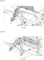
- THE figures 1 to 6 illustrate, for some only partially, a folding agricultural machine (1), which comprises, on the one hand, at least one functional part or section (2) mounted in an articulated manner and capable of being moved alternately between at least a first deployed position and at least one second folded position and, on the other hand, at least one component (3) mounted in an articulated manner and capable of being moved between a first deployed and/or operational position and a second non-operational and/or folded or retracted position.
- a folding agricultural machine (1) which comprises, on the one hand, at least one functional part or section (2) mounted in an articulated manner and capable of being moved alternately between at least a first deployed position and at least one second folded position and, on the other hand, at least one component (3) mounted in an articulated manner and capable of being moved between a first deployed and/or operational position and a second non-operational and/or folded or retracted position.
- said or each component (3) is connected kinematically, at least in traction, via at least one non-elastic flexible mechanical link (4), to the or one functional part or section (2 ) considered, in such a way that a movement of said functional part or section (2) between its first position and its second position automatically leads to a similar movement of said or each component (3) between its first and second positions.
- a link (4) has minimal bulk and can be installed with minimal lateral space relative to the machine.
- the link (4) can be at least partially integrated into the structure of the machine (1) itself and extend along and/or between constituent elements thereof.
- “functional part or section (2)” of the machine (1) we mean a part of the machine which carries, integrates or constitutes at least one tool or working instrument of this machine. Such a part is typically movable between a working position, generally associated with a deployed state, and a transport (or non-use) position, generally associated with a folded state.
- the link (4) makes it possible to reliably control the position or state of said component (3) to the position or state of said functional part (2) to which it is connected.
- the link (4) can be single or multiple (that is to say be formed of a single element or of several elements, in particular at least two elements) depending on the mass to be moved in particular and/or the size of the component.
- the implementation of the aforementioned solution according to the invention is particularly beneficial, in the case where said at least one component (3) is arranged in or on the machine (1) with a positioning such that it interferes with the movement of the functional part or section (2) - from its first to its second position - when said component (3) is outside its second position.
- the invention provides a simple, reliable and adaptable solution, certainly avoiding any interference (during the folding of this part) between said component and said folding part and making it possible to avoid any oversight or error.
- the link (4) will be configured in such a way that at least the volume of potential interference, occupied both by the component in the deployed state and by the folding part in the folded state , is released (or is gradually released at least) by the component when the folding part engages with it (and possibly vice versa).
- inventive solution does not require or depend on any actuator and does not need any source of energy (electric, pneumatic or hydraulic) and constitutes a safety element in the use of the machine ( 1) by automating a securing operation which could be forgotten by the operator and cause damage to the machine.
- the latter comprises at least one sliding guide means (5), where appropriate with a change of direction, for the or each mechanical link (4).
- the or each mechanical link (4) consists of an elongated flexible element that is substantially non-elastic, at least in its longitudinal direction, such as a chain, a ribbon or a cable, advantageously with metal strands.
- said machine (1) comprises at least one means (5) for guiding this mechanical link (4), in particular in sliding, with or without change of direction, under the shape of a rail, an angle gear, a tube, a ring, a pulley, a pinion or the like, this or each guide means (5) being located on the path of the or each mechanical link (4) and of course adapted to the nature of said link (4).
- guide means (5) in the form of tube portions are shown, but those skilled in the art will understand that at the level of changes in direction of the flexible mechanical link (4) of the returns (pulley, rail , pinions, etc.7) are typically present to guide its movement.
- a guiding means (5) in the form of a tube can extend around and over one or more portions or over the entire length of a mechanical link (4) in the form of a cable , thus forming a Bowden type cable.
- a mechanical link (4) in the form of a cable thus forming a Bowden type cable.
- the presence of such guiding means can be easily identified by those skilled in the art, even if they are not specifically represented (see in particular at the places of change of direction/orientation of the link mechanical).
- the link (4) can comprise at least two cables (or at least one cable and at least one chain) having the same attachment point ((2' ) and/or (3')) or preferably distinct fixing points ((2') and/or (3')) making it possible to distribute the stresses at the level of the component and/or part concerned.
- the connection of the latter with the functional part (2) can be carried out indifferently at any location of the latter, which leads to less dependence on the kinematics and the configuration of this part.
- the movement of movement of the functional part or section (2) considered between its first position and its second position consists of a pivoting around a folding axis (AR ), the latter connecting said functional part or section (2) to a chassis part (1') or to a similar supporting structure of the machine (1).
- the movement of movement of the component (3) considered between its first position and its second position under the action of the mechanical link (4) comprises , in particular or exclusively, a pivoting around an axis (AR'), which advantageously connects said component (3) to the chassis (1') or to a similar supporting structure of the machine (1).
- This axis (AR') can be parallel, perpendicular ( figures 5 And 6 ) or inclined ( figures 1 to 4 ) relative to an axis or the folding axis (AR) connecting said functional part or section (2) to the chassis (1') or to a similar supporting structure of the machine (1).
- the movement of movement of the component (3) considered between its first position and its second position under the action of the mechanical link (4) further comprises sliding and /or a pivot around another axis, the displacement movements respectively of a functional part or section (2) and of a component (3) connected to the latter by a mechanical link (4) being of angular amplitude identical or different and/or synchronous or temporally delayed.
- the mechanical link (4) is removably fixed to the component (3) and/or to the functional part or section (2) considered, the where necessary interchangeable without tools (fixing by nesting or hanging).
- its length can be adjustable.
- a device for maintaining constant tension on the link (4) can also be provided, to guarantee movement synchronism without dead band, for example mounted at one of the fixing points of said link (4).
- Such a tensioning device can for example simply consist of a spring presenting a resistance to deformation compatible with the load to be moved.
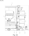
- said at least one component (3) considered is mounted articulated on a chassis part (1') or a similar supporting structure of the machine (1), against which the functional part or section (2) folds in its second position, said component (3) also being folded against said chassis part (1') or similar supporting structure in its second position, being located between this chassis part (1') or similar supporting structure and said functional part or section (2).
- said at least one component (3) considered is mounted articulated on a chassis part (1') or a similar supporting structure of the machine (1), against which comes against fold the functional part or section (2) into its second position, said component (3) being moved outside the path of movement of said chassis part (1') or similar supporting structure towards a second retracted position located in the outside the space between this frame part (1') or similar supporting structure and said functional part or section (2) in its second position.
- the mechanical link (4) can have axial rigidity properties, allowing the transmission of a thrust force requesting the movement of the component (3) from its second position to its first position when the functional part or section (2) moves from its second position to its first position.
- a small initial thrust of the mechanical link (4) is sufficient for this return to take place automatically.
- said at least one component (3) consists of a support, access and/or circulation means for an operator, such as a ladder, a footbridge, a platform or the like and is advantageously mounted in an articulated manner on a frame part (1') of the hopper type or a similar tank, or on a support structure of the latter.
- a mechanical link (4) such a component (3) which is only useful during the work and maintenance phases and whose bulk must be reduced as much as possible during the transport and storage, is automatically retracted and folded by drive depending on the folding movement of the lateral part (2) to which it is directly connected by this link.
- This retraction movement illustrated herein as being an upward folding movement by pivoting, can alternatively be a combined movement (rotation around several axes, rotation + translation), a sliding movement or other.
- a mechanical link (4) in the form of a flexible cable allows a wide variety of transformation and transmission of movement.
- the interest of the invention is of course crucial when the constitution of the machine (1) is such that the component (3) risks being crushed by the functional part (2) which folds, in particular due to a oversight on the part of the operator.
- the machine (1) can include another component (6) of the medium support type, complementary to the component in the form of a staircase.
- This other component (6) can possibly, depending on its location in particular, also be mounted in an articulated manner and undergo movement between an deployed position and a folded position depending on the configuration of the machine (1). This movement can be carried out independently of the movement of a folding functional part (2), or be controlled beforehand or simultaneously with it (by means of an actuator for example, dedicated or not).
- this other component (6) can also, like the aforementioned articulated component (3), be connected kinematically by a mechanical link to the folding functional part (2) concerned and be moved together with it (not shown) .
- the functional part or section (2) in its second position constitutes a holding stop of the component (3) in its second position, in particular when the latter constitutes an unstable raised position.
Landscapes
- Life Sciences & Earth Sciences (AREA)
- Soil Sciences (AREA)
- Engineering & Computer Science (AREA)
- Mechanical Engineering (AREA)
- Environmental Sciences (AREA)
- Agricultural Machines (AREA)
Applications Claiming Priority (1)
| Application Number | Priority Date | Filing Date | Title |
|---|---|---|---|
| FR2210668A FR3140733B1 (fr) | 2022-10-17 | 2022-10-17 | Machine agricole repliable avec une partie et un composant reliés cinématiquement entre eux |
Publications (1)
| Publication Number | Publication Date |
|---|---|
| EP4356705A1 true EP4356705A1 (de) | 2024-04-24 |
Family
ID=84362443
Family Applications (1)
| Application Number | Title | Priority Date | Filing Date |
|---|---|---|---|
| EP23203266.4A Pending EP4356705A1 (de) | 2022-10-17 | 2023-10-12 | Klappbare landwirtschaftliche maschine mit kinematisch miteinander verbundenen komponenten |
Country Status (2)
| Country | Link |
|---|---|
| EP (1) | EP4356705A1 (de) |
| FR (1) | FR3140733B1 (de) |
Citations (4)
| Publication number | Priority date | Publication date | Assignee | Title |
|---|---|---|---|---|
| DE3925033A1 (de) * | 1989-07-28 | 1991-02-07 | Deere & Co | Leiter mit einem oberen und einem unteren sprossenteil |
| US7431221B2 (en) * | 2005-05-16 | 2008-10-07 | Cnh Canada, Ltd. | Lock assembly for a multiple stage folding boom assembly |
| US7469915B2 (en) * | 2006-05-03 | 2008-12-30 | Cnh America, Llc | Access assembly to adjacent product storage tanks on a planting implement |
| WO2022010405A1 (en) * | 2020-07-06 | 2022-01-13 | Väderstad Holding Ab | Agricultural implement with folding operator platform and method of folding an operator platform |
-
2022
- 2022-10-17 FR FR2210668A patent/FR3140733B1/fr active Active
-
2023
- 2023-10-12 EP EP23203266.4A patent/EP4356705A1/de active Pending
Patent Citations (4)
| Publication number | Priority date | Publication date | Assignee | Title |
|---|---|---|---|---|
| DE3925033A1 (de) * | 1989-07-28 | 1991-02-07 | Deere & Co | Leiter mit einem oberen und einem unteren sprossenteil |
| US7431221B2 (en) * | 2005-05-16 | 2008-10-07 | Cnh Canada, Ltd. | Lock assembly for a multiple stage folding boom assembly |
| US7469915B2 (en) * | 2006-05-03 | 2008-12-30 | Cnh America, Llc | Access assembly to adjacent product storage tanks on a planting implement |
| WO2022010405A1 (en) * | 2020-07-06 | 2022-01-13 | Väderstad Holding Ab | Agricultural implement with folding operator platform and method of folding an operator platform |
Also Published As
| Publication number | Publication date |
|---|---|
| FR3140733B1 (fr) | 2024-11-08 |
| FR3140733A1 (fr) | 2024-04-19 |
Similar Documents
| Publication | Publication Date | Title |
|---|---|---|
| CA2744503C (fr) | Dispositif de raccourcissement d'un atterrisseur d'aeronef | |
| EP0511922B1 (de) | Mähmaschine mit schwenkbarer Kupplungsstruktur | |
| EP2225933B1 (de) | Bewegliche Schneidevorrichtung | |
| EP0570314A1 (de) | Maschine zum Schneiden, insbesondere Mähmaschine, die sich den Bodenunebenheiten leicht anpasst | |
| WO2011157807A1 (fr) | Atterrisseur principal d'aeronef a deux balanciers articules sur la structure de l'aeronef | |
| EP0552120B1 (de) | Heumaschine mit dynamischer Entlastungsvorrichtung | |
| WO2011157808A1 (fr) | Atterrisseur principal d'aeronef a deux balanciers et structure a parallelogramme deformable | |
| EP3713391B1 (de) | Landwirtschaftliche maschine mit einem vereinfachten sicherheitssystem, das es einem werkzeug oder einer gruppe von werkzeugen, die durch einen tragarm mit einem anhängebock verbunden sind, ermöglicht, eine sicherheitsbewegung auszuführen | |
| FR2643610A1 (fr) | Atterrisseur d'avion a roues orientables lors du relevage de l'atterrisseur | |
| FR2887396A1 (fr) | Tondeuse a gazon autoportee ayant une unite de tondeuse frontale | |
| FR2816166A1 (fr) | Machine robotisee de taille d'arbustes ou d'arbres tels que des arbres fruitiers | |
| EP4356705A1 (de) | Klappbare landwirtschaftliche maschine mit kinematisch miteinander verbundenen komponenten | |
| EP1072553A1 (de) | Zusammenklappvorrichtung eines Kranauslegers mit ineinandersetzbaren Elementen | |
| EP2959759B1 (de) | Landwirtschaftliche maschine, die mit einer zentriervorrichtung ausgestattet ist | |
| EP3787392A1 (de) | Landwirtschaftliche maschine mit einem förderer zum ernten von pflanzen | |
| CA3082840A1 (fr) | Machine agricole avec un systeme de securite a cinematique de declenchement amelioree | |
| EP0579564B1 (de) | Mit einem Schlepper zu verbindender Mäher mit einer verbesserten Abstellvorrichtung | |
| FR2627441A1 (fr) | Potence de chargement/dechargement a bras retractable, et vehicule la comportant | |
| EP3868189B1 (de) | Gelenkzugarmvorrichtung und mit einem solchen arm ausgestattete landwirtschaftliche maschine | |
| EP1053670A1 (de) | Böschungsmäher | |
| FR2717344A1 (fr) | Dispositif de manÓoeuvre d'une rampe de pulvérisation. | |
| FR2509711A1 (fr) | Dispositif elevateur a cabine ou plate-forme de travail | |
| FR2786454A1 (fr) | Hayon elevateur retractable | |
| FR2718326A1 (fr) | Dispositif d'effacement de barre de coupe. | |
| FR2882621A1 (fr) | Andaineuse reversible |
Legal Events
| Date | Code | Title | Description |
|---|---|---|---|
| PUAI | Public reference made under article 153(3) epc to a published international application that has entered the european phase |
Free format text: ORIGINAL CODE: 0009012 |
|
| STAA | Information on the status of an ep patent application or granted ep patent |
Free format text: STATUS: THE APPLICATION HAS BEEN PUBLISHED |
|
| AK | Designated contracting states |
Kind code of ref document: A1 Designated state(s): AL AT BE BG CH CY CZ DE DK EE ES FI FR GB GR HR HU IE IS IT LI LT LU LV MC ME MK MT NL NO PL PT RO RS SE SI SK SM TR |
|
| STAA | Information on the status of an ep patent application or granted ep patent |
Free format text: STATUS: REQUEST FOR EXAMINATION WAS MADE |
|
| 17P | Request for examination filed |
Effective date: 20241024 |
|
| RBV | Designated contracting states (corrected) |
Designated state(s): AL AT BE BG CH CY CZ DE DK EE ES FI FR GB GR HR HU IE IS IT LI LT LU LV MC ME MK MT NL NO PL PT RO RS SE SI SK SM TR |