EP3791782A1 - Katheter mit flexibler leiterplatte und fertigungsverfahren für flexible leiterplatte - Google Patents
Katheter mit flexibler leiterplatte und fertigungsverfahren für flexible leiterplatte Download PDFInfo
- Publication number
- EP3791782A1 EP3791782A1 EP19196443.6A EP19196443A EP3791782A1 EP 3791782 A1 EP3791782 A1 EP 3791782A1 EP 19196443 A EP19196443 A EP 19196443A EP 3791782 A1 EP3791782 A1 EP 3791782A1
- Authority
- EP
- European Patent Office
- Prior art keywords
- circuit board
- catheter
- printed circuit
- flexible
- tube
- Prior art date
- Legal status (The legal status is an assumption and is not a legal conclusion. Google has not performed a legal analysis and makes no representation as to the accuracy of the status listed.)
- Granted
Links
Images



Classifications
-
- A—HUMAN NECESSITIES
- A61—MEDICAL OR VETERINARY SCIENCE; HYGIENE
- A61B—DIAGNOSIS; SURGERY; IDENTIFICATION
- A61B5/00—Measuring for diagnostic purposes; Identification of persons
- A61B5/68—Arrangements of detecting, measuring or recording means, e.g. sensors, in relation to patient
- A61B5/6846—Arrangements of detecting, measuring or recording means, e.g. sensors, in relation to patient specially adapted to be brought in contact with an internal body part, i.e. invasive
- A61B5/6847—Arrangements of detecting, measuring or recording means, e.g. sensors, in relation to patient specially adapted to be brought in contact with an internal body part, i.e. invasive mounted on an invasive device
- A61B5/6852—Catheters
-
- A—HUMAN NECESSITIES
- A61—MEDICAL OR VETERINARY SCIENCE; HYGIENE
- A61M—DEVICES FOR INTRODUCING MEDIA INTO, OR ONTO, THE BODY; DEVICES FOR TRANSDUCING BODY MEDIA OR FOR TAKING MEDIA FROM THE BODY; DEVICES FOR PRODUCING OR ENDING SLEEP OR STUPOR
- A61M25/00—Catheters; Hollow probes
- A61M25/0067—Catheters; Hollow probes characterised by the distal end, e.g. tips
- A61M25/0082—Catheter tip comprising a tool
-
- A—HUMAN NECESSITIES
- A61—MEDICAL OR VETERINARY SCIENCE; HYGIENE
- A61B—DIAGNOSIS; SURGERY; IDENTIFICATION
- A61B18/00—Surgical instruments, devices or methods for transferring non-mechanical forms of energy to or from the body
- A61B18/04—Surgical instruments, devices or methods for transferring non-mechanical forms of energy to or from the body by heating
- A61B18/12—Surgical instruments, devices or methods for transferring non-mechanical forms of energy to or from the body by heating by passing a current through the tissue to be heated, e.g. high-frequency current
- A61B18/14—Probes or electrodes therefor
-
- A—HUMAN NECESSITIES
- A61—MEDICAL OR VETERINARY SCIENCE; HYGIENE
- A61B—DIAGNOSIS; SURGERY; IDENTIFICATION
- A61B18/00—Surgical instruments, devices or methods for transferring non-mechanical forms of energy to or from the body
- A61B18/04—Surgical instruments, devices or methods for transferring non-mechanical forms of energy to or from the body by heating
- A61B18/12—Surgical instruments, devices or methods for transferring non-mechanical forms of energy to or from the body by heating by passing a current through the tissue to be heated, e.g. high-frequency current
- A61B18/14—Probes or electrodes therefor
- A61B18/1492—Probes or electrodes therefor having a flexible, catheter-like structure, e.g. for heart ablation
-
- A—HUMAN NECESSITIES
- A61—MEDICAL OR VETERINARY SCIENCE; HYGIENE
- A61B—DIAGNOSIS; SURGERY; IDENTIFICATION
- A61B5/00—Measuring for diagnostic purposes; Identification of persons
- A61B5/24—Detecting, measuring or recording bioelectric or biomagnetic signals of the body or parts thereof
- A61B5/25—Bioelectric electrodes therefor
- A61B5/279—Bioelectric electrodes therefor specially adapted for particular uses
- A61B5/28—Bioelectric electrodes therefor specially adapted for particular uses for electrocardiography [ECG]
- A61B5/283—Invasive
- A61B5/287—Holders for multiple electrodes, e.g. electrode catheters for electrophysiological study [EPS]
-
- A—HUMAN NECESSITIES
- A61—MEDICAL OR VETERINARY SCIENCE; HYGIENE
- A61N—ELECTROTHERAPY; MAGNETOTHERAPY; RADIATION THERAPY; ULTRASOUND THERAPY
- A61N1/00—Electrotherapy; Circuits therefor
- A61N1/02—Details
- A61N1/04—Electrodes
- A61N1/05—Electrodes for implantation or insertion into the body, e.g. heart electrode
-
- A—HUMAN NECESSITIES
- A61—MEDICAL OR VETERINARY SCIENCE; HYGIENE
- A61N—ELECTROTHERAPY; MAGNETOTHERAPY; RADIATION THERAPY; ULTRASOUND THERAPY
- A61N1/00—Electrotherapy; Circuits therefor
- A61N1/18—Applying electric currents by contact electrodes
- A61N1/32—Applying electric currents by contact electrodes alternating or intermittent currents
- A61N1/36—Applying electric currents by contact electrodes alternating or intermittent currents for stimulation
- A61N1/362—Heart stimulators
-
- H—ELECTRICITY
- H05—ELECTRIC TECHNIQUES NOT OTHERWISE PROVIDED FOR
- H05K—PRINTED CIRCUITS; CASINGS OR CONSTRUCTIONAL DETAILS OF ELECTRIC APPARATUS; MANUFACTURE OF ASSEMBLAGES OF ELECTRICAL COMPONENTS
- H05K1/00—Printed circuits
- H05K1/02—Details
- H05K1/0277—Bendability or stretchability details
- H05K1/028—Bending or folding regions of flexible printed circuits
-
- H—ELECTRICITY
- H05—ELECTRIC TECHNIQUES NOT OTHERWISE PROVIDED FOR
- H05K—PRINTED CIRCUITS; CASINGS OR CONSTRUCTIONAL DETAILS OF ELECTRIC APPARATUS; MANUFACTURE OF ASSEMBLAGES OF ELECTRICAL COMPONENTS
- H05K3/00—Apparatus or processes for manufacturing printed circuits
- H05K3/0011—Working of insulating substrates or insulating layers
- H05K3/0044—Mechanical working of the substrate, e.g. drilling or punching
-
- A—HUMAN NECESSITIES
- A61—MEDICAL OR VETERINARY SCIENCE; HYGIENE
- A61B—DIAGNOSIS; SURGERY; IDENTIFICATION
- A61B18/00—Surgical instruments, devices or methods for transferring non-mechanical forms of energy to or from the body
- A61B2018/00571—Surgical instruments, devices or methods for transferring non-mechanical forms of energy to or from the body for achieving a particular surgical effect
- A61B2018/00577—Ablation
-
- A—HUMAN NECESSITIES
- A61—MEDICAL OR VETERINARY SCIENCE; HYGIENE
- A61B—DIAGNOSIS; SURGERY; IDENTIFICATION
- A61B18/00—Surgical instruments, devices or methods for transferring non-mechanical forms of energy to or from the body
- A61B2018/00571—Surgical instruments, devices or methods for transferring non-mechanical forms of energy to or from the body for achieving a particular surgical effect
- A61B2018/00601—Cutting
-
- A—HUMAN NECESSITIES
- A61—MEDICAL OR VETERINARY SCIENCE; HYGIENE
- A61B—DIAGNOSIS; SURGERY; IDENTIFICATION
- A61B18/00—Surgical instruments, devices or methods for transferring non-mechanical forms of energy to or from the body
- A61B18/04—Surgical instruments, devices or methods for transferring non-mechanical forms of energy to or from the body by heating
- A61B18/12—Surgical instruments, devices or methods for transferring non-mechanical forms of energy to or from the body by heating by passing a current through the tissue to be heated, e.g. high-frequency current
- A61B18/14—Probes or electrodes therefor
- A61B2018/1405—Electrodes having a specific shape
- A61B2018/1435—Spiral
-
- A—HUMAN NECESSITIES
- A61—MEDICAL OR VETERINARY SCIENCE; HYGIENE
- A61B—DIAGNOSIS; SURGERY; IDENTIFICATION
- A61B2562/00—Details of sensors; Constructional details of sensor housings or probes; Accessories for sensors
- A61B2562/02—Details of sensors specially adapted for in-vivo measurements
- A61B2562/0209—Special features of electrodes classified in A61B5/24, A61B5/25, A61B5/283, A61B5/291, A61B5/296, A61B5/053
-
- A—HUMAN NECESSITIES
- A61—MEDICAL OR VETERINARY SCIENCE; HYGIENE
- A61B—DIAGNOSIS; SURGERY; IDENTIFICATION
- A61B2562/00—Details of sensors; Constructional details of sensor housings or probes; Accessories for sensors
- A61B2562/12—Manufacturing methods specially adapted for producing sensors for in-vivo measurements
-
- A—HUMAN NECESSITIES
- A61—MEDICAL OR VETERINARY SCIENCE; HYGIENE
- A61B—DIAGNOSIS; SURGERY; IDENTIFICATION
- A61B2562/00—Details of sensors; Constructional details of sensor housings or probes; Accessories for sensors
- A61B2562/16—Details of sensor housings or probes; Details of structural supports for sensors
- A61B2562/164—Details of sensor housings or probes; Details of structural supports for sensors the sensor is mounted in or on a conformable substrate or carrier
-
- A—HUMAN NECESSITIES
- A61—MEDICAL OR VETERINARY SCIENCE; HYGIENE
- A61B—DIAGNOSIS; SURGERY; IDENTIFICATION
- A61B2562/00—Details of sensors; Constructional details of sensor housings or probes; Accessories for sensors
- A61B2562/16—Details of sensor housings or probes; Details of structural supports for sensors
- A61B2562/166—Details of sensor housings or probes; Details of structural supports for sensors the sensor is mounted on a specially adapted printed circuit board
-
- A—HUMAN NECESSITIES
- A61—MEDICAL OR VETERINARY SCIENCE; HYGIENE
- A61B—DIAGNOSIS; SURGERY; IDENTIFICATION
- A61B2562/00—Details of sensors; Constructional details of sensor housings or probes; Accessories for sensors
- A61B2562/22—Arrangements of medical sensors with cables or leads; Connectors or couplings specifically adapted for medical sensors
- A61B2562/221—Arrangements of sensors with cables or leads, e.g. cable harnesses
- A61B2562/222—Electrical cables or leads therefor, e.g. coaxial cables or ribbon cables
-
- H—ELECTRICITY
- H05—ELECTRIC TECHNIQUES NOT OTHERWISE PROVIDED FOR
- H05K—PRINTED CIRCUITS; CASINGS OR CONSTRUCTIONAL DETAILS OF ELECTRIC APPARATUS; MANUFACTURE OF ASSEMBLAGES OF ELECTRICAL COMPONENTS
- H05K2203/00—Indexing scheme relating to apparatus or processes for manufacturing printed circuits covered by H05K3/00
- H05K2203/02—Details related to mechanical or acoustic processing, e.g. drilling, punching, cutting, using ultrasound
- H05K2203/0228—Cutting, sawing, milling or shearing
Definitions
- the invention relates to a catheter according to the preamble of claim 1 with a flexible printed circuit board and a method for manufacturing a flexible printed circuit board according to claim 6.
- catheters that carry electrodes, such as those in the DE 694 01 562 T2 are described.
- mapping catheters for example for three-dimensional recording of the anatomy of a heart chamber, which must have a large number of electrodes, are also known.
- the object of the present invention is to create an inexpensive and at the same time flexible catheter and to at least partially remedy the disadvantages of the prior art. Another object is to describe a cost-effective manufacturing process for flexible printed circuit boards which can be used in such a catheter.
- the catheter has the shape of an elongated, hollow and flexible tube, which could also be referred to as a hose. It is a hollow catheter.
- the catheter has at least one electrode for carrying out a diagnosis, for example a measurement such as an electrophysiological examination, or for carrying out a therapy, for example an operation such as a catheter ablation, in each case in the human body.
- the at least one electrode is arranged at one end region of the tube and an electrical connection is attached to the other end region of the tube for electrically connecting the catheter to a control device, so that there is a current-conducting and data transmission connection between the at least one electrode and the electrical connection.
- the at least one electrode and the electrical connection are advantageously connected to one another in an electrically conductive manner by means of conductor tracks on at least one flexible printed circuit board.
- the flexible printed circuit board is in particular film-like and pliable but not necessarily stretchable. Polyimide (PI), for example, can be used as the material.
- the conductor tracks can in particular be made of copper or of copper alloys.
- the flexible printed circuit board is arranged in the tube, ie inside the hollow tube. Such a catheter is particularly inexpensive to manufacture, since no individual electrical conductors have to be laid. By using a flexible circuit board inside the tube, the catheter is also very flexible.
- the circuit board has the shape of a long strip. This has the advantage that a single printed circuit board can then be sufficient to establish the connection between the electrode and the electrical connection over the entire length of the pipe.
- the strip is cut out of a flexible printed circuit board in a spiral shape as a strip of constant width.
- a flexible printed circuit board is particularly inexpensive to manufacture. Further details can be found below from the description of the manufacturing method according to the invention.
- the band is undulating, ie is wound in a spiral shape in its longitudinal axis direction.
- the tape can be pleated, ie provided with a zigzag fold.
- a deformed printed circuit board of this type is particularly good at coping with the bending movements of the pipe, tolerates even tight bending radii, and prevents the printed circuit board from being subjected to high expansions during the bending movement and from breaking the conductor tracks. If the circuit board is also rotated about the longitudinal axis of the catheter, the degrees of freedom of the circuit board are further increased and damage to the circuit board is prevented even better.
- Such a manufacturing method for producing a flexible printed circuit board is particularly cost-effective because on the one hand it saves material and on the other hand it is fast because a device for applying the conductor tracks and a tool for cutting out only a comparatively small area must be able to achieve, so only small relative movements have to be realized. It is also advantageous that the strip-shaped printed circuit board is automatically undulated and thus good flexibility of the printed circuit board is achieved.
- the spiral has a constant winding spacing, so that a band of constant width is created.
- the spiral is then an involute of a circle.
- the separation takes place by punching or cutting, in particular flame cutting or beam cutting, such as, for example, water jet cutting or laser beam cutting.
- pleating i.e. zigzag folding, of the tape can be carried out.
- the invention also relates to the use of a catheter as described above as a cardiac catheter which is used in the diagnosis or therapy of the human heart.
- Fig. 1 shows a catheter 10 according to the invention, which has the shape of an elongated, flexible tube 1. At least one electrode 2 is arranged at one of its end regions. An electrical connection 3 is attached to its other end region. The at least one electrode 2 is connected via conductor tracks 5 on an elastically stretchable printed circuit board 4 (not shown in detail here) within the tube 1 to the electrical connection 3 in terms of data transmission and electricity. A control device 11, which is used to control the catheter 10, is connected to the connection 3.
- Fig. 2a shows a material-saving and cost-effective way of manufacturing a printed circuit board 4.
- a flexible carrier plate 8 is provided.
- conductor tracks 5 are applied to the flexible ones Carrier plate 8 for producing a flat printed circuit board 4.
- the conductor tracks 5 are only indicated in the figure.
- a strip is then severed from the flat printed circuit board 4, the dividing line 9 having the shape of a helical spiral, i.e. h an Archimedean spiral.
- the winding spacing a of the spiral is constant, so that a band of constant width is created.
- Figure 2b shows an alternative, material-saving and cost-effective option for manufacturing a printed circuit board 4, which is particularly advantageous when a plurality of electrodes are provided on a catheter.
- a flexible carrier plate 8 is first provided.
- conductor tracks 5 are applied to the flexible carrier plate 8 to produce a flat circuit board 4.
- the conductor tracks 5 are only indicated as lines in the figure, although in practice they preferably have a meander shape .
- the electrodes 2 and electrical connections 3 can also be applied.
- a strip is then cut out of the flat circuit board 4, the dividing line 9 having the shape of a string of a straight line, a semicircle and another straight line, i.e. a U-shape with two legs and a curvature connecting the legs.
- Electrodes 2 and electrical connections 3 are in the straight areas and can thus be produced more easily.
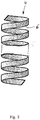
- Fig. 3 shows a printed circuit board 4 in the form of a long strip with undulation 6, which extends through the in Fig. 2 Manufacturing process shown results.
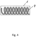
- Such an undulated circuit board 4 can be positioned within a tube 1 to create a catheter 10, as in FIG Fig. 4 shown.
- Fig. 5 shows the process of pleating a strip-shaped printed circuit board 4.
- Pleating that is to say creating a pleated blind 7, takes place by folding the printed circuit board 4 in a zigzag fashion.
Landscapes
- Health & Medical Sciences (AREA)
- Life Sciences & Earth Sciences (AREA)
- Engineering & Computer Science (AREA)
- Veterinary Medicine (AREA)
- Public Health (AREA)
- Biomedical Technology (AREA)
- Heart & Thoracic Surgery (AREA)
- General Health & Medical Sciences (AREA)
- Animal Behavior & Ethology (AREA)
- Surgery (AREA)
- Medical Informatics (AREA)
- Molecular Biology (AREA)
- Physics & Mathematics (AREA)
- Biophysics (AREA)
- Cardiology (AREA)
- Nuclear Medicine, Radiotherapy & Molecular Imaging (AREA)
- Pathology (AREA)
- Microelectronics & Electronic Packaging (AREA)
- Radiology & Medical Imaging (AREA)
- Otolaryngology (AREA)
- Plasma & Fusion (AREA)
- Anesthesiology (AREA)
- Hematology (AREA)
- Pulmonology (AREA)
- Manufacturing & Machinery (AREA)
- Physiology (AREA)
- Media Introduction/Drainage Providing Device (AREA)
- Structure Of Printed Boards (AREA)
Abstract
Description
- Die Erfindung betrifft einen Katheter gemäß dem Oberbegriff von Anspruch 1 mit einer flexiblen Leiterplatte und ein Verfahren zur Fertigung einer flexiblen Leiterplatte gemäß Anspruch 6.
- Aus dem Stand der Technik sind unterschiedlichste Bauformen von Kathetern bekannt, welche ihrer medizinischen Anwendung entsprechend aufgebaut sind. Darunter sind auch elektrodentragende Katheter wie sie beispielsweise in der
DE 694 01 562 T2 beschrieben sind. Auch bekannt sind sogenannte Mappingkatheter, beispielsweise zur 3-dimensionalen Erfassung der Anatomie einer Herzkammer, welche eine hohe Anzahl an Elektroden aufweisen müssen. - Bei den aus dem Stand der Technik bekannten Kathetern entstehen hohe Produktionskosten, weil die zu den Elektroden führenden Leiterbahnen aufwändig im Katheterrohr untergebracht werden müssen. Weiter problematisch ist, dass sich auf Grund der verwendeten Materialien eine Beschränkung bzgl. des Biegeradius des Katheters ergeben kann und damit eine Einschränkung in dessen Einsatz.
- Aufgabe der vorliegenden Erfindung ist es, einen kostengünstigen und gleichzeitig flexiblen Katheter zu schaffen und die Nachteile des Standes der Technik zumindest teilweise zu beheben. Weitere Aufgabe ist es, ein kostengünstiges Fertigungsverfahren für flexible Leiterplatten zu beschreiben, welche in einem solchen Katheter eingesetzt werden können.
- Gelöst wird diese Aufgabe durch einen Katheter mit den Merkmalen von Anspruch 1.
- Erfindungsgemäß wurde als vorteilhaft erkannt eine flexible Leiterplatte mit Leiterbahnen zu verwenden:
Der Katheter hat die Form eines länglichen, hohlen und flexiblen Rohres, welches auch als Schlauch bezeichnet werden könnte. Es handelt sich um einen Hohlkatheter. Der Katheter besitzt mindestens eine Elektrode zur Durchführung einer Diagnose, beispielsweise einer Messung wie einer elektrophysiologischen Untersuchung, oder zur Durchführung einer Therapie, beispielsweise einer Operation wie einer Katheterablation, jeweils im menschlichen Körper. Die mindestens eine Elektrode ist an einem Endbereich des Rohres angeordnet und am anderen Endbereich des Rohres ist ein elektrischer Anschluss angebracht zum elektrischen Verbinden des Katheters mit einer Steuereinrichtung, sodass eine stromleitende und datenübertragungstechnische Verbindung zwischen der mindestens eine Elektrode und dem elektrischen Anschluss besteht. - In vorteilhafter Weise sind die mindestens eine Elektrode und der elektrische Anschluss mittels Leiterbahnen auf mindestens einer flexiblen Leiterplatte elektrisch leitend miteinander verbunden. Die flexible Leiterplatte ist insbesondere filmartig und biegeschlaff aber nicht notwendigerweise dehnbar. Als Material kann beispielsweise Polyimid (PI) eingesetzt werden. Die Leiterbahnen können insbesondere aus Kupfer oder aus Kupferlegierungen gefertigt sein. Gemäß der Erfindung ist die flexible Leiterplatte in dem Rohr angeordnet, d. h. innerhalb des hohlen Rohres.
Ein derartiger Katheter ist besonders kostengünstig in seiner Fertigung, da keine einzelnen Stromleiter verlegt werden müssen. Durch die Verwendung einer flexiblen Leiterplatte im Inneren des Rohres ist der Katheter auch sehr flexibel. - In einer besonders vorteilhaften und daher bevorzugten Weiterbildung des erfindungsgemäßen Katheters weist die Leiterplatte die Form eines langen Bandes auf. Dies hat den Vorteil, dass dann eine einzige Leiterplatte genügen kann, um die Verbindung von Elektrode und elektrischen Anschluss über die ganze Länge des Rohres herzustellen.
- Besonders vorteilhaft erscheint es, wenn das Band als Band konstanter Breite schneckenförmig aus einer flexiblen Leiterplatte herausgetrennt ist. Eine derartige flexible Leiterplatte ist besonders kostengünstig in ihrer Herstellung. Näheres geht untenstehend aus der Beschreibung des erfindungsgemäßen Fertigungsverfahrens hervor.
- Es hat sich als besonders vorteilhaft erwiesen, wenn das Band onduliert ist, d.h. in seiner Längsachsrichtung spiralförmig gewunden ist. Zusätzlich oder alternativ kann das Band plissiert sein, d. h. mit einer Zickzack Faltung versehen sein.
- Eine derartige verformte Leiterplatte kann Biegebewegungen des Rohres besonders gut mitmachen, toleriert selbst enge Biegeradien, und es wird verhindert, dass auf die Leiterplatte bei der Biegebewegung hohe Dehnungen wirken und die Leiterbahnen brechen könnten.
Erfolgt zusätzlich ein Verdrehen der Leiterplatte um die Längsachse des Katheters, so werden die Freiheitsgrade der Leiterplatte weiter erhöht und eine Beschädigung der Leiterplatte noch besser verhindert. - Die Erfindung betrifft auch ein Verfahren zur Fertigung einer flexiblen Leiterplatte in Form eines langen Bandes, insbesondere für einen Katheter wie obenstehend beschrieben, mit folgenden Schritten:
- a. Bereitstellen einer flexiblen Trägerplatte.
- b. Aufbringen von Leiterbahnen auf die flexiblen Trägerplatte zur Herstellung einer flächigen Leiterplatte.
- c. Heraustrennen eines Bandes aus der flächigen Leiterplatte, wobei die Trennlinie die Form einer schneckenförmigen Spirale aufweist, d. h einer Archimedischen Spirale. In einer Alternativen Verfahrensvariante kann die Trennlinie eine U-Form aufweisen, mit zwei Schenkeln und einer die Schenkel verbindenden Krümmung.
- d. Als zusätzlicher fakultativer Schritt kann abschließend ein Strecken des Bandes durch Aufbringen von entgegengesetzten Zugkräften an den Enden des Bandes erfolgen. Dadurch wird die Spirale zu einem langen, ondulierten Band aufgezogen.
- Ein derartiges Fertigungsverfahren zur Herstellung einer flexiblen Leiterplatte ist besonders kostengünstig, da es zum einen materialsparend ist und zum anderen schnell ist, weil eine Einrichtung zum Aufbringen der Leiterbahnen und ein Werkzeug zum Heraustrennen nur eine vergleichsweise kleine Fläche erreichen können muss, also nur kleine Relativbewegungen realisiert werden müssen.
Weiter vorteilhaft ist, dass sich eine Ondulierung der bandförmigen Leiterplatte automatisch ergibt und damit eine gute Flexibilität der Leiterplatte erreicht wird. - Es hat sich als besonders vorteilhaft erwiesen, wenn die Spirale einen konstanten Windungsabstand aufweist, derart dass ein Band konstanter Breite entsteht. Bei der Spirale handelt es sich dann um eine Kreisevolvente.
- In vorteilhafter Weiterbildung des erfindungsgemäßen Verfahrens erfolgt das Trennen durch Stanzen oder Schneiden, insbesondere Brennschneiden oder Strahlschneiden, wie beispielsweise Wasserstrahlschneiden oder Laserstrahlschneiden.
- Fakultativ kann in einem zusätzlichen Schritt des Verfahrens ein Plissieren, d.h. Zickzack-Falten des Bandes erfolgen.
- Die Erfindung betrifft auch die Verwendung eines wie obenstehend beschriebenen Katheters als Herzkatheter, welcher in der Diagnose oder Therapie des menschlichen Herzens zum Einsatz gelangt.
- Die beschriebene Erfindung und die beschriebenen vorteilhaften Weiterbildungen der Erfindung stellen auch in Kombination miteinander - soweit dies technisch sinnvoll ist - vorteilhafte Weiterbildungen der Erfindung dar.
- Hinsichtlich weiterer Vorteile und in konstruktiver und funktioneller Hinsicht vorteilhafter Ausgestaltungen der Erfindung wird auf die Unteransprüche sowie die Beschreibung von Ausführungsbeispielen unter Bezugnahme auf die beiliegenden Figuren verwiesen.
- Die Erfindung soll an Hand beigefügter Figuren noch näher erläutert werden. Einander entsprechende Elemente und Bauteile sind in den Figuren mit gleichen Bezugszeichen versehen. Zugunsten einer besseren Übersichtlichkeit der Figuren wurde auf eine maßstabsgetreue Darstellung verzichtet.
Es zeigen in schematischer Darstellung - Fig. 1
- einen erfindungsgemäßen Katheter
- Fig. 2a
- eine materialsparende und kostengünstige Fertigung einer Leiterplatte
- Fig. 2b
- eine alternative materialsparende und kostengünstige Fertigung einer Leiterplatte
- Fig. 3
- eine Leiterplatte in ondulierter Form
- Fig. 4
- eine ondulierte Leiterplatte innerhalb eines Rohres
- Fig. 5
- den Vorgang des Plissierens einer Leiterplatte
-
Fig. 1 zeigt einen erfindungsgemäßen Katheter 10, welcher die Form eines länglichen, flexiblen Rohres 1 besitzt. An seinem einen Endbereich ist mindestens eine Elektrode 2 angeordnet. An seinem anderen Endbereich ist ein elektrischer Anschluss 3 angebracht. Die mindestens eine Elektrode 2 ist über Leiterbahnen 5 auf einer elastisch dehnbaren Leiterplatte 4 (hier nicht näher dargestellt) innerhalb des Rohres 1 mit dem elektrischen Anschluss 3 datenübertragungstechnisch und stromleitend verbunden. An den Anschluss 3 ist eine Steuereinrichtung 11 angeschlossen, welche zur Steuerung des Katheters 10 dient. -
Fig. 2a zeigt eine materialsparende und kostengünstige Möglichkeit zur Fertigung einer Leiterplatte 4. Es erfolgt zuerst ein Bereitstellen einer flexiblen Trägerplatte 8. Danach erfolgt ein Aufbringen von Leiterbahnen 5 auf die flexiblen Trägerplatte 8 zur Herstellung einer flächigen Leiterplatte 4. Die Leiterbahnen 5 sind in der Figur nur angedeutet. Sodann erfolgt ein Heraustrennen eines Bandes aus der flächigen Leiterplatte 4, wobei die Trennlinie 9 die Form einer schneckenförmigen Spirale aufweist, d. h einer Archimedischen Spirale. Der Windungsabstand a der Spirale ist konstant, derart, dass ein Band konstanter Breite entsteht. -
Fig. 2b zeigt eine alternative materialsparende und kostengünstige Möglichkeit zur Fertigung einer Leiterplatte 4, welche besonders vorteilhaft ist, wenn mehrere Elektroden an einem Katheder vorgesehen sind. Es erfolgt zuerst ein Bereitstellen einer flexiblen Trägerplatte 8. Danach erfolgt ein Aufbringen von Leiterbahnen 5 auf die flexiblen Trägerplatte 8 zur Herstellung einer flächigen Leiterplatte 4. Die Leiterbahnen 5 sind in der Figur nur als Linien angedeutet, obwohl sie in der Praxis bevorzugt eine Mäanderform aufweisen. Auch die Elektroden 2 und elektrischen Anschlüsse 3 können aufgebracht werden. Sodann erfolgt ein Heraustrennen eines Bandes aus der flächigen Leiterplatte 4, wobei die Trennlinie 9 die Form einer Aneinanderreihung einer Geraden, eines Halbkreises und nochmals einer Geraden aufweist, also einer U-Form mit zwei Schenkeln und einer die Schenkel verbindenden Krümmung. Elektroden 2 und elektrische Anschlüsse 3 liegen in den geraden Bereichen und können so einfacher hergestellt werden. -
Fig. 3 zeigt eine Leiterplatte 4 in Form eines langen Bandes mit Ondulierung 6, welche sich durch das inFig. 2 gezeigte Fertigungsverfahren ergibt. Eine derartig ondulierte Leiterplatte 4 kann zur Schaffung eines Katheters 10 innerhalb eines Rohres 1 positioniert sein, wie inFig. 4 gezeigt. -
Fig. 5 zeigt den Vorgang des Plissierens einer bandförmigen Leiterplatte 4. Das Plissieren, d.h. Erzeugen eines Plissee 7 erfolgt durch zickzackartiges Falten der Leiterplatte 4. -
- 1
- Rohr
- 2
- Elektrode
- 3
- Anschluss
- 4
- Leiterplatte
- 5
- Position Leiterbahn
- 6
- Ondulierung
- 7
- Plissee
- 8
- Trägerplatte
- 9
- Trennlinie
- 10
- Katheter
- 11
- Steuereinrichtung
- a
- Windungsabstand
Claims (9)
- Katheter (10) in Form eines länglichen, hohlen und flexiblen Rohres (1) mit mindestens einer Elektrode (2) zur Durchführung einer Diagnose oder Therapie im menschlichen Körper, wobei die mindestens eine Elektrode (2) an einem Endbereich des Rohres (1) angeordnet ist und am anderen Endbereich des Rohres (1) ein elektrischer Anschluss (3) angebracht ist, zum elektrischen Verbinden des Katheters (10) mit einer Steuereinrichtung (11),
dadurch gekennzeichnet, dass
die mindestens eine Elektrode (2) und der elektrische Anschluss (3) mittels Leiterbahnen (5) auf einer flexiblen Leiterplatte (4) elektrische leitend miteinander verbunden sind und, dass
die flexible Leiterplatte (4) in dem Rohr (1) angeordnet ist. - Katheter nach Anspruch 1, dadurch gekennzeichnet, dass
die Leiterplatte (4) die Form eines langen Bandes aufweist. - Katheter nach Anspruch 2, dadurch gekennzeichnet, dass
das Band als Band konstanter Breite schneckenförmig aus einer flexiblen Leiterplatte (4) herausgetrennt ist. - Katheter nach einem der Ansprüche 2 oder 3, dadurch gekennzeichnet, dass
das Band onduliert ist. - Katheter nach einem der Ansprüche 2 bis 4, dadurch gekennzeichnet, dass
das Band plissiert ist. - Verfahren zur Fertigung einer flexiblen Leiterplatte (4) in Form eines langen Bandes, insbesondere für einen Katheter (10) nach einem der vorangehenden Ansprüche,
mit folgenden Schritten:a. Bereitstellen einer flexiblen Trägerplatte (8),b. Aufbringen von Leiterbahnen (5) auf die flexiblen Trägerplatte (8) zur Herstellung einer flächigen Leiterplatte (4),c. Heraustrennen eines Bandes aus der flächigen Leiterplatte (4), wobei die Trennlinie (9) die Form einer schneckenförmigen Spirale oder eine U-Form aufweist. - Verfahren nach Anspruch 6, dadurch gekennzeichnet, dass
die Spirale einen konstanten Windungsabstand (a) aufweist. - Verfahren nach einem der Ansprüche 6 oder 7 dadurch gekennzeichnet, dass
das Heraustrennen durch Stanzen oder Schneiden erfolgt. - Verfahren nach einem der Ansprüche 6 bis 8 mit dem zusätzlichen Schritt- Plissieren (7) des Bandes.
Priority Applications (2)
| Application Number | Priority Date | Filing Date | Title |
|---|---|---|---|
| EP19196443.6A EP3791782B8 (de) | 2019-09-10 | 2019-09-10 | Katheter mit flexibler leiterplatte und fertigungsverfahren für flexible leiterplatte |
| US17/015,099 US20210069469A1 (en) | 2019-09-10 | 2020-09-09 | Catheter comprising flexible printed circuit board and manufacturing method for flexible circuit board |
Applications Claiming Priority (1)
| Application Number | Priority Date | Filing Date | Title |
|---|---|---|---|
| EP19196443.6A EP3791782B8 (de) | 2019-09-10 | 2019-09-10 | Katheter mit flexibler leiterplatte und fertigungsverfahren für flexible leiterplatte |
Publications (3)
| Publication Number | Publication Date |
|---|---|
| EP3791782A1 true EP3791782A1 (de) | 2021-03-17 |
| EP3791782B1 EP3791782B1 (de) | 2023-08-02 |
| EP3791782B8 EP3791782B8 (de) | 2023-09-06 |
Family
ID=68109085
Family Applications (1)
| Application Number | Title | Priority Date | Filing Date |
|---|---|---|---|
| EP19196443.6A Active EP3791782B8 (de) | 2019-09-10 | 2019-09-10 | Katheter mit flexibler leiterplatte und fertigungsverfahren für flexible leiterplatte |
Country Status (2)
| Country | Link |
|---|---|
| US (1) | US20210069469A1 (de) |
| EP (1) | EP3791782B8 (de) |
Citations (8)
| Publication number | Priority date | Publication date | Assignee | Title |
|---|---|---|---|---|
| DE69401562T2 (de) | 1993-10-12 | 1997-05-15 | Arrow Int Investment | Katheter mit einer Elektrode sowie Verfahren zu ihrer Herstellung |
| JP2006244968A (ja) * | 2005-03-07 | 2006-09-14 | Fujikura Ltd | 配線構造 |
| US20060244177A1 (en) * | 2005-04-19 | 2006-11-02 | Masayuki Kaneto | Flexible printed circuit board for catheter, catheter using same, and production method of catheter |
| US20070219551A1 (en) * | 2003-09-22 | 2007-09-20 | Honour Kirk S | Medical device with flexible printed circuit |
| US20120172696A1 (en) * | 2009-09-10 | 2012-07-05 | Cathprint Ab | Flexible Conductor Carrier for Catheter and Catheter Fitted with a Conductor Carrier |
| US20160113729A1 (en) * | 2009-03-10 | 2016-04-28 | Medtronic Xomed, Inc. | Navigated Malleable Surgical Instrument |
| WO2016171597A1 (en) * | 2015-04-24 | 2016-10-27 | Cathprint Ab | Flexible pcb with mounted components |
| US20190175056A1 (en) * | 2017-12-07 | 2019-06-13 | Biosense Webster (Israel) Ltd. | Catheter and method for catheter assembly |
Family Cites Families (2)
| Publication number | Priority date | Publication date | Assignee | Title |
|---|---|---|---|---|
| US5795299A (en) * | 1997-01-31 | 1998-08-18 | Acuson Corporation | Ultrasonic transducer assembly with extended flexible circuits |
| US20160270732A1 (en) * | 2015-03-17 | 2016-09-22 | Cathprint Ab | Low profile medical device with bonded base for electrical components |
-
2019
- 2019-09-10 EP EP19196443.6A patent/EP3791782B8/de active Active
-
2020
- 2020-09-09 US US17/015,099 patent/US20210069469A1/en not_active Abandoned
Patent Citations (8)
| Publication number | Priority date | Publication date | Assignee | Title |
|---|---|---|---|---|
| DE69401562T2 (de) | 1993-10-12 | 1997-05-15 | Arrow Int Investment | Katheter mit einer Elektrode sowie Verfahren zu ihrer Herstellung |
| US20070219551A1 (en) * | 2003-09-22 | 2007-09-20 | Honour Kirk S | Medical device with flexible printed circuit |
| JP2006244968A (ja) * | 2005-03-07 | 2006-09-14 | Fujikura Ltd | 配線構造 |
| US20060244177A1 (en) * | 2005-04-19 | 2006-11-02 | Masayuki Kaneto | Flexible printed circuit board for catheter, catheter using same, and production method of catheter |
| US20160113729A1 (en) * | 2009-03-10 | 2016-04-28 | Medtronic Xomed, Inc. | Navigated Malleable Surgical Instrument |
| US20120172696A1 (en) * | 2009-09-10 | 2012-07-05 | Cathprint Ab | Flexible Conductor Carrier for Catheter and Catheter Fitted with a Conductor Carrier |
| WO2016171597A1 (en) * | 2015-04-24 | 2016-10-27 | Cathprint Ab | Flexible pcb with mounted components |
| US20190175056A1 (en) * | 2017-12-07 | 2019-06-13 | Biosense Webster (Israel) Ltd. | Catheter and method for catheter assembly |
Also Published As
| Publication number | Publication date |
|---|---|
| EP3791782B1 (de) | 2023-08-02 |
| EP3791782B8 (de) | 2023-09-06 |
| US20210069469A1 (en) | 2021-03-11 |
Similar Documents
| Publication | Publication Date | Title |
|---|---|---|
| DE69924082T2 (de) | Aktives schlankes Röhrchen und Verfahren zur Herstellung | |
| DE69929963T2 (de) | Medizinische Leitung mit einem Sigmamerkmal | |
| DE69630305T2 (de) | Elektrodenkatheter | |
| DE3779828T2 (de) | Schraubenfoermig gewickelter flexibler schlauch. | |
| EP2384248B1 (de) | Dreidimensionale drahtstruktur in leichtbauweise und verfahren zu deren herstellung | |
| EP3181188B1 (de) | Dehnbare elektrode | |
| DE1955516B2 (de) | Implantable elektrodenanordnung | |
| DE102013109505A1 (de) | Medizinisches Instrument und elektrochirurgisches System | |
| EP1038547A2 (de) | Dilatierbare Herzelektrodenanordnung zur Implantation insbesondere im Koronarsinus des Herzens | |
| DE2329426C3 (de) | Elektrischer Verbinder und Verfahren zu seiner Herstellung | |
| EP3970261A1 (de) | Stator für eine elektrische maschine mit bandförmiger wicklungseinheit für eine statorwicklung und verfahren zu dessen herstellung | |
| DE3031752A1 (de) | Mehrpolige schrittmacherleistung | |
| EP3756725A1 (de) | Implantierbare elktrodenleitung mit zu einem geflechtverbundenen leitern | |
| EP3791782B1 (de) | Katheter mit flexibler leiterplatte und fertigungsverfahren für flexible leiterplatte | |
| DE2361270A1 (de) | Gedruckter flachspulensatz | |
| EP0092797B1 (de) | Mehrpolige elektrische Leitung | |
| EP0335109A1 (de) | Verfahren zur Herstellung eines Heizelements | |
| DE1265807B (de) | Elektrische Kleinsteckverbindung und Verfahren zu ihrer Herstellung | |
| EP3797678A1 (de) | Katheter mit dehnbarer leiterplatte | |
| DE3038815A1 (de) | Sonde fuer ein stroemungsgeschwindigkeits-messgeraet | |
| EP3473200B1 (de) | Ablationskatheter mit mikroelektrode und verfahren zum herstellen eines ablationskatheters | |
| DE102004035002A1 (de) | Elektrische Verbindungsleitung für implantierte Komponenten sowie Verfahren zur Herstellung | |
| EP3957231A1 (de) | Flexible leiterplatte und katheter mit einer solchen leiterplatte | |
| DE2629032A1 (de) | Schlauch, insbesondere saugschlauch mit einer elektrischen leitung | |
| DE102024108531A1 (de) | Leitung für eine medizinische Vorrichtung |
Legal Events
| Date | Code | Title | Description |
|---|---|---|---|
| PUAI | Public reference made under article 153(3) epc to a published international application that has entered the european phase |
Free format text: ORIGINAL CODE: 0009012 |
|
| STAA | Information on the status of an ep patent application or granted ep patent |
Free format text: STATUS: THE APPLICATION HAS BEEN PUBLISHED |
|
| AK | Designated contracting states |
Kind code of ref document: A1 Designated state(s): AL AT BE BG CH CY CZ DE DK EE ES FI FR GB GR HR HU IE IS IT LI LT LU LV MC MK MT NL NO PL PT RO RS SE SI SK SM TR |
|
| AX | Request for extension of the european patent |
Extension state: BA ME |
|
| RAP1 | Party data changed (applicant data changed or rights of an application transferred) |
Owner name: FREUDENBERG SE |
|
| STAA | Information on the status of an ep patent application or granted ep patent |
Free format text: STATUS: REQUEST FOR EXAMINATION WAS MADE |
|
| 17P | Request for examination filed |
Effective date: 20210902 |
|
| RBV | Designated contracting states (corrected) |
Designated state(s): AL AT BE BG CH CY CZ DE DK EE ES FI FR GB GR HR HU IE IS IT LI LT LU LV MC MK MT NL NO PL PT RO RS SE SI SK SM TR |
|
| REG | Reference to a national code |
Ref country code: DE Ref legal event code: R079 Free format text: PREVIOUS MAIN CLASS: A61B0005042000 Ipc: A61B0005287000 Ref country code: DE Ref legal event code: R079 Ref document number: 502019008730 Country of ref document: DE Free format text: PREVIOUS MAIN CLASS: A61B0005042000 Ipc: A61B0005287000 |
|
| GRAP | Despatch of communication of intention to grant a patent |
Free format text: ORIGINAL CODE: EPIDOSNIGR1 |
|
| STAA | Information on the status of an ep patent application or granted ep patent |
Free format text: STATUS: GRANT OF PATENT IS INTENDED |
|
| RIC1 | Information provided on ipc code assigned before grant |
Ipc: A61B 5/287 20210101AFI20230203BHEP |
|
| INTG | Intention to grant announced |
Effective date: 20230309 |
|
| GRAS | Grant fee paid |
Free format text: ORIGINAL CODE: EPIDOSNIGR3 |
|
| GRAA | (expected) grant |
Free format text: ORIGINAL CODE: 0009210 |
|
| STAA | Information on the status of an ep patent application or granted ep patent |
Free format text: STATUS: THE PATENT HAS BEEN GRANTED |
|
| REG | Reference to a national code |
Ref country code: DE Ref legal event code: R081 Ref document number: 502019008730 Country of ref document: DE Owner name: CARL FREUDENBERG KG, DE Free format text: FORMER OWNER: FREUDENBERG SE, 69469 WEINHEIM, DE |
|
| AK | Designated contracting states |
Kind code of ref document: B1 Designated state(s): AL AT BE BG CH CY CZ DE DK EE ES FI FR GB GR HR HU IE IS IT LI LT LU LV MC MK MT NL NO PL PT RO RS SE SI SK SM TR |
|
| REG | Reference to a national code |
Ref country code: GB Ref legal event code: FG4D Free format text: NOT ENGLISH |
|
| REG | Reference to a national code |
Ref country code: CH Ref legal event code: PK Free format text: BERICHTIGUNG B8 Ref country code: CH Ref legal event code: EP |
|
| RAP2 | Party data changed (patent owner data changed or rights of a patent transferred) |
Owner name: CARL FREUDENBERG KG |
|
| REG | Reference to a national code |
Ref country code: DE Ref legal event code: R096 Ref document number: 502019008730 Country of ref document: DE |
|
| REG | Reference to a national code |
Ref country code: IE Ref legal event code: FG4D Free format text: LANGUAGE OF EP DOCUMENT: GERMAN |
|
| P01 | Opt-out of the competence of the unified patent court (upc) registered |
Effective date: 20230816 |
|
| REG | Reference to a national code |
Ref country code: LT Ref legal event code: MG9D |
|
| REG | Reference to a national code |
Ref country code: NL Ref legal event code: MP Effective date: 20230802 |
|
| PG25 | Lapsed in a contracting state [announced via postgrant information from national office to epo] |
Ref country code: GR Free format text: LAPSE BECAUSE OF FAILURE TO SUBMIT A TRANSLATION OF THE DESCRIPTION OR TO PAY THE FEE WITHIN THE PRESCRIBED TIME-LIMIT Effective date: 20231103 |
|
| PG25 | Lapsed in a contracting state [announced via postgrant information from national office to epo] |
Ref country code: IS Free format text: LAPSE BECAUSE OF FAILURE TO SUBMIT A TRANSLATION OF THE DESCRIPTION OR TO PAY THE FEE WITHIN THE PRESCRIBED TIME-LIMIT Effective date: 20231202 |
|
| PG25 | Lapsed in a contracting state [announced via postgrant information from national office to epo] |
Ref country code: SE Free format text: LAPSE BECAUSE OF FAILURE TO SUBMIT A TRANSLATION OF THE DESCRIPTION OR TO PAY THE FEE WITHIN THE PRESCRIBED TIME-LIMIT Effective date: 20230802 Ref country code: RS Free format text: LAPSE BECAUSE OF FAILURE TO SUBMIT A TRANSLATION OF THE DESCRIPTION OR TO PAY THE FEE WITHIN THE PRESCRIBED TIME-LIMIT Effective date: 20230802 Ref country code: PT Free format text: LAPSE BECAUSE OF FAILURE TO SUBMIT A TRANSLATION OF THE DESCRIPTION OR TO PAY THE FEE WITHIN THE PRESCRIBED TIME-LIMIT Effective date: 20231204 Ref country code: NO Free format text: LAPSE BECAUSE OF FAILURE TO SUBMIT A TRANSLATION OF THE DESCRIPTION OR TO PAY THE FEE WITHIN THE PRESCRIBED TIME-LIMIT Effective date: 20231102 Ref country code: NL Free format text: LAPSE BECAUSE OF FAILURE TO SUBMIT A TRANSLATION OF THE DESCRIPTION OR TO PAY THE FEE WITHIN THE PRESCRIBED TIME-LIMIT Effective date: 20230802 Ref country code: LV Free format text: LAPSE BECAUSE OF FAILURE TO SUBMIT A TRANSLATION OF THE DESCRIPTION OR TO PAY THE FEE WITHIN THE PRESCRIBED TIME-LIMIT Effective date: 20230802 Ref country code: LT Free format text: LAPSE BECAUSE OF FAILURE TO SUBMIT A TRANSLATION OF THE DESCRIPTION OR TO PAY THE FEE WITHIN THE PRESCRIBED TIME-LIMIT Effective date: 20230802 Ref country code: IS Free format text: LAPSE BECAUSE OF FAILURE TO SUBMIT A TRANSLATION OF THE DESCRIPTION OR TO PAY THE FEE WITHIN THE PRESCRIBED TIME-LIMIT Effective date: 20231202 Ref country code: HR Free format text: LAPSE BECAUSE OF FAILURE TO SUBMIT A TRANSLATION OF THE DESCRIPTION OR TO PAY THE FEE WITHIN THE PRESCRIBED TIME-LIMIT Effective date: 20230802 Ref country code: GR Free format text: LAPSE BECAUSE OF FAILURE TO SUBMIT A TRANSLATION OF THE DESCRIPTION OR TO PAY THE FEE WITHIN THE PRESCRIBED TIME-LIMIT Effective date: 20231103 Ref country code: FI Free format text: LAPSE BECAUSE OF FAILURE TO SUBMIT A TRANSLATION OF THE DESCRIPTION OR TO PAY THE FEE WITHIN THE PRESCRIBED TIME-LIMIT Effective date: 20230802 |
|
| PG25 | Lapsed in a contracting state [announced via postgrant information from national office to epo] |
Ref country code: PL Free format text: LAPSE BECAUSE OF FAILURE TO SUBMIT A TRANSLATION OF THE DESCRIPTION OR TO PAY THE FEE WITHIN THE PRESCRIBED TIME-LIMIT Effective date: 20230802 |
|
| PG25 | Lapsed in a contracting state [announced via postgrant information from national office to epo] |
Ref country code: ES Free format text: LAPSE BECAUSE OF FAILURE TO SUBMIT A TRANSLATION OF THE DESCRIPTION OR TO PAY THE FEE WITHIN THE PRESCRIBED TIME-LIMIT Effective date: 20230802 |
|
| PG25 | Lapsed in a contracting state [announced via postgrant information from national office to epo] |
Ref country code: SM Free format text: LAPSE BECAUSE OF FAILURE TO SUBMIT A TRANSLATION OF THE DESCRIPTION OR TO PAY THE FEE WITHIN THE PRESCRIBED TIME-LIMIT Effective date: 20230802 Ref country code: RO Free format text: LAPSE BECAUSE OF FAILURE TO SUBMIT A TRANSLATION OF THE DESCRIPTION OR TO PAY THE FEE WITHIN THE PRESCRIBED TIME-LIMIT Effective date: 20230802 Ref country code: ES Free format text: LAPSE BECAUSE OF FAILURE TO SUBMIT A TRANSLATION OF THE DESCRIPTION OR TO PAY THE FEE WITHIN THE PRESCRIBED TIME-LIMIT Effective date: 20230802 Ref country code: EE Free format text: LAPSE BECAUSE OF FAILURE TO SUBMIT A TRANSLATION OF THE DESCRIPTION OR TO PAY THE FEE WITHIN THE PRESCRIBED TIME-LIMIT Effective date: 20230802 Ref country code: DK Free format text: LAPSE BECAUSE OF FAILURE TO SUBMIT A TRANSLATION OF THE DESCRIPTION OR TO PAY THE FEE WITHIN THE PRESCRIBED TIME-LIMIT Effective date: 20230802 Ref country code: CZ Free format text: LAPSE BECAUSE OF FAILURE TO SUBMIT A TRANSLATION OF THE DESCRIPTION OR TO PAY THE FEE WITHIN THE PRESCRIBED TIME-LIMIT Effective date: 20230802 Ref country code: SK Free format text: LAPSE BECAUSE OF FAILURE TO SUBMIT A TRANSLATION OF THE DESCRIPTION OR TO PAY THE FEE WITHIN THE PRESCRIBED TIME-LIMIT Effective date: 20230802 |
|
| REG | Reference to a national code |
Ref country code: CH Ref legal event code: PL |
|
| REG | Reference to a national code |
Ref country code: DE Ref legal event code: R097 Ref document number: 502019008730 Country of ref document: DE |
|
| PG25 | Lapsed in a contracting state [announced via postgrant information from national office to epo] |
Ref country code: LU Free format text: LAPSE BECAUSE OF NON-PAYMENT OF DUE FEES Effective date: 20230910 |
|
| REG | Reference to a national code |
Ref country code: BE Ref legal event code: MM Effective date: 20230930 |
|
| PG25 | Lapsed in a contracting state [announced via postgrant information from national office to epo] |
Ref country code: LU Free format text: LAPSE BECAUSE OF NON-PAYMENT OF DUE FEES Effective date: 20230910 Ref country code: MC Free format text: LAPSE BECAUSE OF FAILURE TO SUBMIT A TRANSLATION OF THE DESCRIPTION OR TO PAY THE FEE WITHIN THE PRESCRIBED TIME-LIMIT Effective date: 20230802 |
|
| PLBE | No opposition filed within time limit |
Free format text: ORIGINAL CODE: 0009261 |
|
| STAA | Information on the status of an ep patent application or granted ep patent |
Free format text: STATUS: NO OPPOSITION FILED WITHIN TIME LIMIT |
|
| 26N | No opposition filed |
Effective date: 20240503 |
|
| PG25 | Lapsed in a contracting state [announced via postgrant information from national office to epo] |
Ref country code: CH Free format text: LAPSE BECAUSE OF NON-PAYMENT OF DUE FEES Effective date: 20230930 |
|
| PG25 | Lapsed in a contracting state [announced via postgrant information from national office to epo] |
Ref country code: CH Free format text: LAPSE BECAUSE OF NON-PAYMENT OF DUE FEES Effective date: 20230930 Ref country code: SI Free format text: LAPSE BECAUSE OF FAILURE TO SUBMIT A TRANSLATION OF THE DESCRIPTION OR TO PAY THE FEE WITHIN THE PRESCRIBED TIME-LIMIT Effective date: 20230802 |
|
| PG25 | Lapsed in a contracting state [announced via postgrant information from national office to epo] |
Ref country code: BE Free format text: LAPSE BECAUSE OF NON-PAYMENT OF DUE FEES Effective date: 20230930 |
|
| PG25 | Lapsed in a contracting state [announced via postgrant information from national office to epo] |
Ref country code: BG Free format text: LAPSE BECAUSE OF FAILURE TO SUBMIT A TRANSLATION OF THE DESCRIPTION OR TO PAY THE FEE WITHIN THE PRESCRIBED TIME-LIMIT Effective date: 20230802 |
|
| PG25 | Lapsed in a contracting state [announced via postgrant information from national office to epo] |
Ref country code: BG Free format text: LAPSE BECAUSE OF FAILURE TO SUBMIT A TRANSLATION OF THE DESCRIPTION OR TO PAY THE FEE WITHIN THE PRESCRIBED TIME-LIMIT Effective date: 20230802 |
|
| PG25 | Lapsed in a contracting state [announced via postgrant information from national office to epo] |
Ref country code: CY Free format text: LAPSE BECAUSE OF FAILURE TO SUBMIT A TRANSLATION OF THE DESCRIPTION OR TO PAY THE FEE WITHIN THE PRESCRIBED TIME-LIMIT; INVALID AB INITIO Effective date: 20190910 |
|
| PG25 | Lapsed in a contracting state [announced via postgrant information from national office to epo] |
Ref country code: HU Free format text: LAPSE BECAUSE OF FAILURE TO SUBMIT A TRANSLATION OF THE DESCRIPTION OR TO PAY THE FEE WITHIN THE PRESCRIBED TIME-LIMIT; INVALID AB INITIO Effective date: 20190910 |
|
| PGFP | Annual fee paid to national office [announced via postgrant information from national office to epo] |
Ref country code: DE Payment date: 20250926 Year of fee payment: 7 |
|
| PGFP | Annual fee paid to national office [announced via postgrant information from national office to epo] |
Ref country code: IT Payment date: 20250922 Year of fee payment: 7 |
|
| PGFP | Annual fee paid to national office [announced via postgrant information from national office to epo] |
Ref country code: GB Payment date: 20250923 Year of fee payment: 7 |
|
| PGFP | Annual fee paid to national office [announced via postgrant information from national office to epo] |
Ref country code: FR Payment date: 20250925 Year of fee payment: 7 |
|
| PGFP | Annual fee paid to national office [announced via postgrant information from national office to epo] |
Ref country code: IE Payment date: 20250917 Year of fee payment: 7 |
|
| REG | Reference to a national code |
Ref country code: AT Ref legal event code: MM01 Ref document number: 1593736 Country of ref document: AT Kind code of ref document: T Effective date: 20240910 |
|
| PG25 | Lapsed in a contracting state [announced via postgrant information from national office to epo] |
Ref country code: TR Free format text: LAPSE BECAUSE OF FAILURE TO SUBMIT A TRANSLATION OF THE DESCRIPTION OR TO PAY THE FEE WITHIN THE PRESCRIBED TIME-LIMIT Effective date: 20230802 |
|
| PG25 | Lapsed in a contracting state [announced via postgrant information from national office to epo] |
Ref country code: AT Free format text: LAPSE BECAUSE OF NON-PAYMENT OF DUE FEES Effective date: 20240910 |
|
| PGFP | Annual fee paid to national office [announced via postgrant information from national office to epo] |
Ref country code: AT Payment date: 20260410 Year of fee payment: 5 |