EP3791759A1 - Verfahren zum manipulieren von ablagen oder unterteilungen von mobilen vorratselementen mittels einer handlingvorrichtung und mobiles vorratselement - Google Patents
Verfahren zum manipulieren von ablagen oder unterteilungen von mobilen vorratselementen mittels einer handlingvorrichtung und mobiles vorratselement Download PDFInfo
- Publication number
- EP3791759A1 EP3791759A1 EP20188341.0A EP20188341A EP3791759A1 EP 3791759 A1 EP3791759 A1 EP 3791759A1 EP 20188341 A EP20188341 A EP 20188341A EP 3791759 A1 EP3791759 A1 EP 3791759A1
- Authority
- EP
- European Patent Office
- Prior art keywords
- storage element
- shelf
- mobile storage
- mobile
- shelves
- Prior art date
- Legal status (The legal status is an assumption and is not a legal conclusion. Google has not performed a legal analysis and makes no representation as to the accuracy of the status listed.)
- Granted
Links
- 238000000034 method Methods 0.000 title claims abstract description 8
- 238000001514 detection method Methods 0.000 claims description 4
- 238000004519 manufacturing process Methods 0.000 claims description 2
- 239000002023 wood Substances 0.000 description 4
- 238000005192 partition Methods 0.000 description 3
- 239000002983 wood substitute Substances 0.000 description 3
- 230000004888 barrier function Effects 0.000 description 1
- 238000009434 installation Methods 0.000 description 1
Images


Classifications
-
- A—HUMAN NECESSITIES
- A47—FURNITURE; DOMESTIC ARTICLES OR APPLIANCES; COFFEE MILLS; SPICE MILLS; SUCTION CLEANERS IN GENERAL
- A47F—SPECIAL FURNITURE, FITTINGS, OR ACCESSORIES FOR SHOPS, STOREHOUSES, BARS, RESTAURANTS OR THE LIKE; PAYING COUNTERS
- A47F5/00—Show stands, hangers, or shelves characterised by their constructional features
- A47F5/10—Adjustable or foldable or dismountable display stands
-
- A—HUMAN NECESSITIES
- A47—FURNITURE; DOMESTIC ARTICLES OR APPLIANCES; COFFEE MILLS; SPICE MILLS; SUCTION CLEANERS IN GENERAL
- A47F—SPECIAL FURNITURE, FITTINGS, OR ACCESSORIES FOR SHOPS, STOREHOUSES, BARS, RESTAURANTS OR THE LIKE; PAYING COUNTERS
- A47F5/00—Show stands, hangers, or shelves characterised by their constructional features
- A47F5/0018—Display racks with shelves or receptables
-
- A—HUMAN NECESSITIES
- A47—FURNITURE; DOMESTIC ARTICLES OR APPLIANCES; COFFEE MILLS; SPICE MILLS; SUCTION CLEANERS IN GENERAL
- A47F—SPECIAL FURNITURE, FITTINGS, OR ACCESSORIES FOR SHOPS, STOREHOUSES, BARS, RESTAURANTS OR THE LIKE; PAYING COUNTERS
- A47F7/00—Show stands, hangers, or shelves, adapted for particular articles or materials
- A47F7/0042—Show stands, hangers, or shelves, adapted for particular articles or materials for flat articles, e.g. panels, tiles
-
- B—PERFORMING OPERATIONS; TRANSPORTING
- B23—MACHINE TOOLS; METAL-WORKING NOT OTHERWISE PROVIDED FOR
- B23Q—DETAILS, COMPONENTS, OR ACCESSORIES FOR MACHINE TOOLS, e.g. ARRANGEMENTS FOR COPYING OR CONTROLLING; MACHINE TOOLS IN GENERAL CHARACTERISED BY THE CONSTRUCTION OF PARTICULAR DETAILS OR COMPONENTS; COMBINATIONS OR ASSOCIATIONS OF METAL-WORKING MACHINES, NOT DIRECTED TO A PARTICULAR RESULT
- B23Q7/00—Arrangements for handling work specially combined with or arranged in, or specially adapted for use in connection with, machine tools, e.g. for conveying, loading, positioning, discharging, sorting
- B23Q7/10—Arrangements for handling work specially combined with or arranged in, or specially adapted for use in connection with, machine tools, e.g. for conveying, loading, positioning, discharging, sorting by means of magazines
- B23Q7/103—Arrangements for handling work specially combined with or arranged in, or specially adapted for use in connection with, machine tools, e.g. for conveying, loading, positioning, discharging, sorting by means of magazines for flat material
-
- B—PERFORMING OPERATIONS; TRANSPORTING
- B27—WORKING OR PRESERVING WOOD OR SIMILAR MATERIAL; NAILING OR STAPLING MACHINES IN GENERAL
- B27M—WORKING OF WOOD NOT PROVIDED FOR IN SUBCLASSES B27B - B27L; MANUFACTURE OF SPECIFIC WOODEN ARTICLES
- B27M1/00—Working of wood not provided for in subclasses B27B - B27L, e.g. by stretching
- B27M1/08—Working of wood not provided for in subclasses B27B - B27L, e.g. by stretching by multi-step processes
-
- B—PERFORMING OPERATIONS; TRANSPORTING
- B60—VEHICLES IN GENERAL
- B60B—VEHICLE WHEELS; CASTORS; AXLES FOR WHEELS OR CASTORS; INCREASING WHEEL ADHESION
- B60B33/00—Castors in general; Anti-clogging castors
-
- B—PERFORMING OPERATIONS; TRANSPORTING
- B65—CONVEYING; PACKING; STORING; HANDLING THIN OR FILAMENTARY MATERIAL
- B65G—TRANSPORT OR STORAGE DEVICES, e.g. CONVEYORS FOR LOADING OR TIPPING, SHOP CONVEYOR SYSTEMS OR PNEUMATIC TUBE CONVEYORS
- B65G1/00—Storing articles, individually or in orderly arrangement, in warehouses or magazines
- B65G1/02—Storage devices
Definitions
- the invention relates to a handling arrangement for plate-shaped products made of wood or wood substitutes according to the preamble of claim 1.
- the object of the present invention is therefore to provide a handling arrangement for plate-shaped products in which the disadvantages described do not occur.
- the handling device is now able to manipulate shelves or partitions on the mobile storage elements. At least one shelf and / or at least one subdivision device of at least one mobile storage element are thus designed according to the invention so that they can be manipulated by the handling device.
- the handling device is now designed to manipulate the at least one storage and / or subdivision device in such a way that plate-shaped products can be processed by the machine control the specified parts plan can be found in the relevant storage element.
- the mobile storage element is set up by the handling device, which sets up or sets up each mobile storage element individually according to a specified parts plan and thereby removes, takes in, moves, etc.
- the manipulatable shelf and / or dividing device is / are removable and / or displaceable and / or pivotable and / or displaceable.
- the handling device which preferably comprises a handling robot, the mobile storage elements can be adapted and set up very individually to the specified parts plan and the parts to be accommodated in each mobile storage element according to the parts plan.
- the mobile storage element or elements can be designed as a rack trolley so that they can also be easily moved through the work space for transport purposes, also coupled to one another.
- At least one storage element has a detection device which is the correct one or which is not Detects proper reception of one or a plurality of plate-shaped products by the storage element.
- the detection device can be, for example, a light barrier or also a mechanical device which, for example, indicates the slipping of a plate part placed in the storage element and signals to the handling device that a certain part is not in the intended location.
- At least one storage element comprises a stowage device for receiving unneeded shelves and / or dividing devices. These storage elements are then able to fasten parts that are not required or to hang them on them, so that the storage element can also be transported in this configuration in the form of a tray trolley.
- This also includes the possibility of pivoting existing shelves and / or dividing devices from a position of use into a stowed position. For this purpose, the shelves and / or dividing devices are then pivotably arranged on the storage element.
- the handling arrangement according to the invention further comprises a shelf device which has a plurality of receiving spaces for receiving storage elements.
- a shelf device which has a plurality of receiving spaces for receiving storage elements.
- each receiving space has a positioning device and each storage element has a positioning aid that matches it.
- the positioning device and the positioning aid work together in such a way that each storage element is arranged in a defined position at the receiving area. In this way it is ensured that the handling device can then set up and equip the storage elements without errors and in a precisely positioned manner.
- At least one storage element comprises a base - in particular with at least one receptacle - wherein the base is designed to grip a forklift.
- the handling arrangement described above can also be improved by creating an identification system.
- an identification system can be used in different ways.
- the loading status and setup status of the storage elements can be recorded and evaluated. It can also be determined, for example, via tracking devices such as RFID chips, barcodes, QR codes or the like, which are attached in particular to the storage elements and can be detected via a scanning or detection system of the identification system which position a certain supply element is currently located.
- This also includes, in particular, information about where a corresponding storage element is arranged on the shelf of a handling arrangement, how it is equipped and which shelves and / or dividing devices are currently present in the relevant storage element.
- the handling arrangement comprises an identification device which is designed to identify different storage elements with regard to their loading with workpieces and / or their state of equipment, in particular the presence or position of shelves and / or dividing devices.
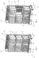
- the storage element 1 shown is preferably designed as a rack trolley with rollers 13 which are attached to a base 10, the following description not necessarily assuming that the mobile storage element 1 must be designed as a trolley. Consequently, the further description also expressly discloses a storage element 1 without rollers.
- the base 10 can have recesses 11, 12 which are suitable, for example, for inserting the fork of a forklift. In this way, the storage element 1 can be lifted and, for example, placed on a shelf (cf. Figure 5 ).
- the storage element 1 also has storage shelves on which plate-shaped workpieces 2 can be placed.
- a rear wall 15 is also provided. The shelves, partitions and / or the rear wall can be brushed to protect the workpieces placed on them (for example indicated by the black stripes in the Figures 1 to 4 ) be coated.
- the storage element 1 has vertical subdivisions 16, 17, a rear wall and a number of shelves, not shown here, on which the workpieces are attached.
- the base 10 also forms in the shown Example of a shelf for workpieces 2.
- a handling device for example a handling robot
- Setting up means here that, depending on the expected part size, subdivisions 16, 17 and trays 18, 19 are individually positioned by the handling device.
- the positioning can either consist in the specific arrangement of the named components on the storage element 1, but it can also consist in the fact that corresponding components are pivoted away, removed or relocated.
- a storage shelf 18 has been removed from its horizontal arrangement and hung on a storage device 20. In this way, the unused part 18 remains on the storage element 1 and is available for a further set-up process.
- FIG 3 is opposite Figure 2 another storage compartment cleared so that the storage shelf 19 can be seen here.
- This storage shelf 19 can, for example, also be removed in the course of the set-up process, and can be hung on a further storage device 20 or swiveled there. This situation is in Figure 4 shown.
- the storage element 1 according to the invention can preferably also comprise a positioning aid 14, which as in the example shown in FIG Figures 1 to 4 is designed as a recess or recess or receptacle.
- a positioning aid 14 provided at the installation site of the storage element 1, can also be used 31 (compare Figure 5 ), be correspondingly conically shaped, for example designed as a bolt, so that it can be received in the positioning aid 14.
- This positioning aid 14 is used for a defined alignment of the storage element 1 so that it can be recognized, for example, by a handling device and properly loaded or equipped.
- FIG. 5 a part of a handling arrangement according to the invention is shown.
- This is a shelf 30 which, in the example shown, has two floors, but can also have more or fewer floors.
- the shelf 30 can accommodate a plurality of storage elements 1.
- Positioning devices 31 are then provided on one or both sides of the storage element 1 at each storage space of the shelf 30, which, after the storage element 1 has been placed on a storage space, can be brought into engagement with the positioning aids 14 provided on the storage element 1.
- the positioning aids 14 have recesses
- the positioning devices 31 are, for example, bolts tapering towards the storage element 1, which in the drawing of FIG Figure 5 can be moved in the horizontal direction for locking and positioning the storage element 1 in the shelf 30.
- other types of positioning devices e.g.
- FIG. 6 an embodiment of a handling arrangement according to the invention is shown in a side view.
- this includes the shelf 30, a handling robot 40 and a further storage area 50 on the side of the handling robot 40 opposite the shelf.
- the handling robot 40 can equip storage elements 1 as described above and then remove plate-shaped workpieces (not shown in this figure) Take tray 50 and sort them into a corresponding storage element 1 in accordance with a predetermined parts plan, or remove corresponding parts from storage element 1 and place them on tray 50.
- the present invention provides a handling arrangement which is able to accommodate workpieces much more effectively in mobile storage elements 1, in particular in the form of mobile storage trolleys. This is achieved in that, depending on a specified parts plan, the handling device, in particular the handling robot, first equips the corresponding mobile storage elements 1 by appropriately positioning, removing, adding, pivoting, etc., shelves or dividing elements. In this way, storage elements 1 are created which enable workpieces to be accommodated in an optimized manner in the work process. In this way, not only can empty spaces be minimized, but parts commissions that belong together can also be distributed to a minimum of storage elements.
Landscapes
- Engineering & Computer Science (AREA)
- Mechanical Engineering (AREA)
- Life Sciences & Earth Sciences (AREA)
- Wood Science & Technology (AREA)
- Forests & Forestry (AREA)
- Warehouses Or Storage Devices (AREA)
Abstract
Description
- Die Erfindung betrifft eine Handlinganordnung für plattenförmige Erzeugnisse aus Holz oder Holzersatzstoffen nach dem Oberbegriff des Anspruchs 1.
- Bei der Holzverarbeitung müssen plattenförmige Erzeugnisse vor ihrer Bearbeitung und gegebenenfalls auch danach sortiert, abgelegt oder sonst wie gefördert oder bevorratet werden. Nicht selten kommen dabei sogenannte mobile Vorratselemente zum Einsatz, beispielsweise sogenannte Hordenwagen, auf denen einzelne Werkstücke platziert werden. Die mobilen Vorratselemente weisen dazu eine Ablage oder eine Mehrzahl Ablagen auf. In der Regel sind diese mobilen Vorratselemente entsprechend den Anforderungen unterteilt und/oder vorgerüstet.
- Zumeist werden für die mobilen Vorratselemente daher standardisierte Einrichtungen verwendet, die eine Vielzahl unterschiedlicher Werkstücke aufnehmen können. Dabei kommt es durchaus vor, dass möglicherweise vorhandene Kapazitäten nicht oder nur unzureichend genutzt werden. Folglich wird die Bestückung der einzelnen mobilen Vorratselemente in der Regel nach einem vorgegebenen Teileplan vorgenommen, um "Leerstellen" in den mobilen Vorratselementen möglichst zu vermeiden. Dies hat wiederum den Nachteil, dass möglicherweise zu einer Kommission gehörende Teile auf unterschiedlichen mobilen Vorratselementen untergebracht werden müssen. Dies ist nachteilig. Folglich kommt es in der Praxis immer wieder vor, dass mobile Vorratselemente nicht optimal ausgelastet sind.
- Aufgabe der vorliegenden Erfindung ist es daher, eine Handlinganordnung für plattenförmige Erzeugnisse zur Verfügung zu stellen, bei welcher die geschilderten Nachteile nicht auftreten.
- Gelöst wird diese Aufgabe durch eine Handlinganordnung mit den Merkmalen des Anspruchs 1. Vorteilhafte Ausführungsformen finden sich in den Unteransprüchen.
- Erfindungsgemäß weist die Handlinganordnung für plattenförmige Erzeugnisse aus Holz oder Holzersatzstoffen dazu folgendes auf:
- Eine Handlingvorrichtung mit einer Mehrzahl zur Aufnahme von plattenförmigen Erzeugnissen ausgelegten mobilen Vorratselementen,
- eine Mehrzahl plattenförmige Erzeugnisse aus Holz oder Holzersatzstoffen und
- eine Maschinensteuerung. Dabei ist vorgesehen, dass jedes mobile Vorratselement wenigstens eine Ablage zur Aufnahme und/oder Ablage von plattenförmigen Erzeugnissen umfasst.
- Erfindungsgemäß ist nun die Handlingvorrichtung in der Lage, Ablagen oder Unterteilungen an den mobilen Vorratselementen zu manipulieren. Wenigstens eine Ablage und/oder wenigstens eine Unterteilungseinrichtung wenigstens eines mobilen Vorratselements sind also erfindungsgemäß durch die Handlingvorrichtung manipulierbar ausgebildet. Die Handlingvorrichtung ist dabei nun dazu ausgelegt, die wenigstens eine Ablage und/oder Unterteilungseinrichtung derart zu manipulieren, dass plattenförmige Erzeugnisse nach einem durch die Maschinensteuerung vorgegebenen Teileplan in dem betreffenden Vorratselement Platz finden. Das Rüsten des mobilen Vorratselements erfolgt also erfindungsgemäß bereits durch die Handlingvorrichtung, die jedes mobile Vorratselement dazu individuell nach einem vorgegebenen Teileplan einrichtet bzw. rüstet und dabei Ablagen und/oder Unterteilungen herausnimmt, hereinnimmt, verschiebt usw. Auf diese Weise ist es möglich, bereits vor der Produktion der nach einem Teileplan vorgegebenen Teile entsprechende Ablagemöglichkeiten so zu schaffen, dass der durch die mobilen Vorratselemente zur Verfügung gestellte Raum individuell und bestmöglich genutzt werden kann. So kann auch erreicht werden, dass zusammengehörige Kommissionen von Plattenteilen auf möglichst wenige mobile Vorratselemente verteilt werden.
- Nach einer vorteilhaften Ausführungsform kann vorgesehen sein, dass die manipulierbare Ablage und/oder Unterteilungseinrichtung entfernbar und/oder versetzbar und/oder verschwenkbar und/oder verschiebbar ist/sind. Auf diese Weise lassen sich mit Hilfe der Handlingvorrichtung, die bevorzugt einen Handlingroboter umfasst, die mobilen Vorratselemente sehr individuell auf den vorgegebenen Teileplan und die in jedem mobilen Vorratselement laut Teileplan unterzubringenden Teile anpassen und rüsten.
- Das oder die mobilen Vorratselemente können dabei als Hordenwagen ausgebildet sein, so dass sie sich auch leicht - auch miteinander gekoppelt - zu Transportzwecken durch den Arbeitsraum bewegen lassen.
- Nach einer weiteren Ausführungsform kann vorgesehen sein, dass wenigstens ein Vorratselement eine Erkennungsvorrichtung aufweist, welche die ordnungsgemäße oder nicht ordnungsgemäße Aufnahme eines oder einer Mehrzahl plattenförmiger Erzeugnisse durch das Vorratselement erkennt. Die Erkennungsvorrichtung kann zum Beispiel eine Lichtschranke oder auch eine mechanische Einrichtung sein, die beispielsweise das Verrutschen eines im Vorratselement platzierten Plattenteils anzeigt und der Handlingvorrichtung signalisiert, dass sich ein bestimmtes Teil nicht am vorgesehenen Ort befindet.
- Beim Rüsten des Vorratselements durch die Handlingvorrichtung kann es vorkommen, dass einzelne Ablageelemente oder Unterteilungen gar nicht benötigt werden. In einem solchen Fall kann es sich anbieten, dass diese nicht benötigten Elemente trotzdem am Vorratselement verbleiben. Dazu kann insbesondere vorgesehen sein, dass wenigstens ein Vorratselement eine Verstaueinrichtung zur Aufnahme nicht benötigter Ablagen und/oder Unterteilungseinrichtungen umfasst. Diese Vorratselemente sind dann in der Lage, entsprechend nicht benötigte Teile zu befestigen oder an ihnen einzuhängen, sodass das Vorratselement auch in Ausgestaltung als Hordenwagen in dieser Konfiguration transportiert werden kann. Dies umfasst auch die Möglichkeit, vorhandene Ablagen und/oder Unterteilungseinrichtungen aus einer Gebrauchslage in eine Verstaulage zu verschwenken. Dazu sind die Ablagen und/oder Unterteilungseinrichtungen dann schwenkbar an dem Vorratselement angeordnet.
- Nach einer besonderen Ausführungsform der vorliegenden Erfindung umfasst die erfindungsgemäße Handlinganordnung weiter eine Regalvorrichtung, die eine Mehrzahl Aufnahmeplätze zur Aufnahme von Vorratselementen aufweist. Auf diese Weise ist es möglich, dass die Handlingvorrichtung die einzelnen Vorratselemente auf geringem Raum rüsten und mit Platten bestücken kann.
- Insbesondere kann hierbei vorgesehen sein, dass jeder Aufnahmeplatz eine Positioniereinrichtung und jedes Vorratselement eine dazu passende Positionierhilfe aufweist. Dabei wirken die Positioniereinrichtung und die Positionierhilfe so zusammen, dass jedes Vorratselement in einer definierten Lage am Aufnahmeplatz angeordnet ist. Auf diese Weise wird sichergestellt, dass dann das Rüsten und Bestücken der Vorratselemente durch die Handlingvorrichtung fehlerfrei und positionsgenau erfolgen kann.
- Bei der Benutzung der Vorratselemente kann es vorkommen, dass diese angehoben werden müssen. Dies kann natürlich durch die Handlingvorrichtung geschehen, beispielsweise aber auch durch Manipulation mit einem Stapler. Folglich ist nach einer weiteren Ausführungsform der vorliegenden Erfindung vorgesehen, dass wenigstens ein Vorratselement einen Sockel - insbesondere mit wenigstens einer Aufnahme umfasst - wobei der Sockel zum Angreifen eines Hubstaplers ausgelegt ist.
- Die oben beschriebene Handlinganordnung kann auch dadurch verbessert werden, dass man ein Identifizierungssystem schafft. Ein solches Identifizierungssystem lässt sich auf unterschiedliche Weise einsetzen. So können beispielsweise der Beladezustand und Rüstzustand der Vorratselemente erfasst und ausgewertet werden. Auch kann beispielsweise über Nachverfolgungseinrichtungen wie RFID-Chips, Barcodes, QR-Codes oder dergleichen, die insbesondere an den Vorratselementen angebracht sind und über ein Scan- bzw. Erfassungssystem des Identifizierungssystems erfasst werden können, bestimmt werden, an welcher Stelle sich ein bestimmtes Vorratselement gerade befindet. Dies umfasst insbesondere auch Informationen darüber, an welcher Stelle im Regal einer Handlinganordnung ein entsprechendes Vorratselement angeordnet ist, wie es bestückt ist und welche Ablagen und/oder Unterteilungseinrichtungen gerade in dem betreffenden Vorratselement vorhanden sind. Nach einer erfindungsgemäßen Ausführungsform ist deshalb vorgesehen, dass die Handlinganordnung eine Identifizierungseinrichtung umfasst, welche dazu ausgelegt ist, unterschiedliche Vorratselemente hinsichtlich ihrer Bestückung mit Werkstücken und/oder ihres Rüstzustands, insbesondere des Vorhandenseins oder der Position von Ablagen und/oder Unterteilungseinrichtungen, zu identifizieren.
- Die Erfindung wird nachfolgend anhand der
Figuren 1 bis 6 näher erläutert. -
Figur 1 zeigt ein erfindungsgemäßes Vorratselement in perspektivischer Ansicht in einer ersten Rüstkonfiguration. -
Figur 2 zeigt ein erfindungsgemäßes Vorratselement in perspektivischer Ansicht in einer zweiten Rüstkonfiguration. -
Figur 3 zeigt ein erfindungsgemäßes Vorratselement in perspektivischer Ansicht in einer dritten Rüstkonfiguration. -
Figur 4 zeigt ein erfindungsgemäßes Vorratselement in perspektivischer Ansicht in einer vierten Rüstkonfiguration. -
Figur 5 zeigt in seitlicher Ansicht eine Regalvorrichtung, in welche eine Mehrzahl Vorratselemente aufgenommen ist. -
Figur 6 zeigt eine erfindungsgemäße Handlinganordnung in seitlicher Ansicht. - Das in den
Figuren 1 bis 4 gezeigte Vorratselement 1 ist bevorzugt als Hordenwagen mit Laufrollen 13 ausgebildet, die an einem Sockel 10 angebracht sind, wobei die folgende Beschreibung nicht zwingend voraussetzt, dass das mobile Vorratselement 1 als Wagen ausgebildet sein muss. Folglich offenbart die weitere Beschreibung ausdrücklich auch ein Vorratselement 1 ohne Rollen. Der Sockel 10 kann zusätzlich oder ergänzend zu den Rollen 13 Aussparungen 11, 12 aufweisen, die etwa zum Einbringen der Gabel eines Hubstaplers geeignet sind. Auf diese Weise lässt sich das Vorratselement 1 anheben und beispielsweise auf einem Regal abstellen (vergleicheFigur 5 ). - Weiter weist das Vorratselement 1 Ablageböden auf, auf denen plattenförmige Werkstücke 2 abgestellt werden können. Zudem gibt es am Vorratselement 1 vertikale Unterteilungen, die als Seitenwände 16 oder Zwischenwände 17 ausgebildet sein können. Ferner ist eine Rückwand 15 vorgesehen. Die Ablagen, Unterteilungen und/oder die Rückwand können zur Schonung der darauf abgelegten Werkstücke mit Bürsten (zum Beispiel angedeutet durch die schwarzen Streifen in den
Figuren 1 bis 4 ) beschichtet sein. - In
Figur 1 weist das Vorratselement 1 vertikale Unterteilungen 16, 17, eine Rückwand und eine Reihe von hier nicht dargestellten Ablagen auf, auf denen die Werkstücke angebracht sind. Auch der Sockel 10 bildet im gezeigten Beispiel eine Ablage für Werkstücke 2. Erfindungsgemäß ist es nun möglich, über eine Handlingvorrichtung (zum Beispiel einen Handlingroboter) das Vorratselement 13 in Abhängigkeit eines vorgesehenen Teileplans zu rüsten. Rüsten bedeutet hier, dass abhängig von der zu erwartenden Teilegröße Unterteilungen 16, 17 sowie Ablagen 18, 19 individuell durch die Handlingvorrichtung positioniert werden. Das Positionieren kann entweder im konkreten Anordnen der genannten Bauteile am Vorratselement 1 bestehen, kann aber auch darin bestehen, dass entsprechende Bauteile weggeschwenkt, entfernt oder versetzt werden. Im Beispiel derFigur 2 ist beispielsweise ein Ablageboden 18 aus seiner horizontalen Anordnung entfernt worden und an einer Verstaueinrichtung 20 eingehängt. Auf diese Weise bleibt das nicht verwendete Teil 18 am Vorratselement 1 vorhanden und steht für einen weiteren Rüstvorgang zur Verfügung. - In
Figur 3 ist gegenüberFigur 2 ein weiteres Ablagefach leergeräumt, sodass hier der Ablageboden 19 zu erkennen ist. Dieser Ablageboden 19 lässt sich im Wege des Rüstvorganges beispielsweise ebenfalls entfernen, und an einer weiteren Verstaueinrichtung 20 einhängen oder dorthin verschwenken. Diese Situation ist inFigur 4 dargestellt. - Das erfindungsgemäße Vorratselement 1 kann bevorzugt auch eine Positionierhilfe 14 umfassen, die wie im gezeigten Beispiel der
Figuren 1 bis 4 als Vertiefung oder Aussparung oder Aufnahme ausgebildet ist. Eine solche Aufnahme kann insbesondere innen konisch zulaufend ausgebildet sein, sodass sie zusätzlich eine Zentrierfunktion aufweist. Ebenso kann das Gegenstück, eine am Aufstellungsort des Vorratselements 1 vorgesehene Positioniereinrichtung 31 (vergleicheFigur 5 ), entsprechend konisch geformt sein, etwa als Bolzen ausgebildet sein, sodass es in die Positionierhilfe 14 aufgenommen werden kann. Diese Positionierhilfe 14 dient einer definierten Ausrichtung des Vorratselements 1, sodass es beispielsweise durch eine Handlingvorrichtung erkannt und ordnungsgemäß beschickt oder gerüstet werden kann. - In
Figur 5 ist ein Teil einer erfindungsgemäßen Handlinganordnung gezeigt. Es handelt sich dabei um ein Regal 30, welches im gezeigten Beispiel zwei Etagen aufweist, allerdings auch mehr oder weniger Etagen aufweisen kann. Das Regal 30 kann eine Mehrzahl Vorratselemente 1 aufnehmen. An jedem Ablageplatz des Regals 30 sind dann einseitig oder beidseitig des Vorratselements 1 Positioniereinrichtungen 31 vorgesehen, die nach Ablage des Vorratselements 1 auf einem Ablageplatz in Eingriff mit den am Vorratselement 1 vorgesehenen Positionierhilfen 14 gebracht werden können. Im gezeigten Beispiel weisen die Positionierhilfen 14 Aussparungen auf, die Positioniereinrichtungen 31 sind beispielsweise in Richtung des Vorratselements 1 konisch zulaufende Bolzen, die in der Zeichnung derFigur 5 zur Arretierung und Positionierung des Vorratselements 1 im Regal 30 in horizontaler Richtung verschoben werden können. Natürlich sind auch andere Arten von Positioniereinrichtungen (z. B. Haken, Schrägflächen usw.) denkbar. Wichtig ist, dass beim Zusammenwirken der Positioniereinrichtungen 31 mit den entsprechenden Positionierhilfen 14 eine definierte Positionierung des Vorratselements 1 erzielt wird, sodass eine nicht gezeigte Maschinensteuerung, die eine Handlingvorrichtung steuert, über Informationen über die genauen Positionen der einzelnen Vorratselemente 1 und der darin abgelegten Teile 2 verfügt. - In
Figur 6 ist schließlich in Seitenansicht eine erfindungsgemäße Ausführungsform einer Handlinganordnung gezeigt. Diese umfasst im vorliegenden Fall das Regal 30, einen Handlingroboter 40 sowie eine weitere Ablagefläche 50 auf der dem Regal gegenüberliegenden Seite des Handlingroboters 40. Der Handlingroboter 40 kann Vorratselemente 1 wie oben beschrieben rüsten und sodann plattenförmige Werkstücke (in dieser Abbildung nicht gezeigt) von der Ablage 50 nehmen und in ein entsprechendes Vorratselement 1 entsprechend einem vorgegebenen Teileplan einsortieren oder aber entsprechende Teile aus dem Vorratselement 1 entnehmen und auf der Ablage 50 ablegen. - Mit der vorliegenden Erfindung wird eine Handlinganordnung bereitgestellt, die in der Lage ist, Werkstücke wesentlich effektiver in - insbesondere als Hordenwagen ausgebildeten - mobilen Vorratselementen 1 unterzubringen. Dies wird dadurch erreicht, dass abhängig von einem vorgegebenen Teileplan zunächst durch die Handlingvorrichtung, insbesondere den Handlingroboter, eine Rüstung der entsprechenden mobilen Vorratselemente 1 erfolgt, indem Ablagen oder Unterteilungselemente entsprechend positioniert, entfernt, hinzugefügt, verschwenkt usw. werden. Auf diese Weise entstehen Vorratselemente 1, die im Arbeitsprozess eine optimierte Unterbringung von Werkstücken ermöglichen. Auf diese Weise können nicht nur Leerräume minimiert werden, sondern es können auch zusammengehörende Teilekommissionen auf ein Minimum von Vorratselementen verteilt werden.
Claims (8)
- Verfahren zum Manipulieren von Ablagen oder Unterteilungen von mobilen Vorratselementen (1) mittels einer Handlingvorrichtung, wobei jedes mobile Vorratselement (1) wenigstens eine Ablage (18, 19) und/oder Unterteilungseinrichtung (16, 17) zur Aufnahme und/ oder Ablage von plattenförmigen Erzeugnissen (2) umfasst,
wobei die Handlingvorrichtung die wenigstens eine Ablage (18, 19) und/oder Unterteilungseinrichtung (16, 17) eines der Vorratselemente (1) derart manipuliert, dass plattenförmige Erzeugnisse (2) nach einem durch vorgegebenen Teileplan in dem betreffenden Vorratselement (1) Platz finden. - Verfahren nach Anspruch 1,
dadurch gekennzeichnet,
dass das mobile Vorratselement (1) gerüstet wird, indem wenigstens eine Ablage (18, 19) und/oder wenigstens eine Unterteilungseinrichtung (16, 17) manipuliert wird, indem die manipulierbare Ablage (18, 19) und/oder Unterteilungseinrichtung (16, 17) durch die Handlingvorrichtung entfernt und/oder versetzt und/oder verschwenkt und/oder verschoben wird/werden. - Verfahren nach einem der vorigen Ansprüche,
dadurch gekennzeichnet,
dass die Manipulation von wenigstens einem der Vorratselemente (1) vor der Produktion der nach einem Teileplan vorgegebenen Teile erfolgt. - Mobiles Vorratselement (1), umfassend wenigstens eine Ablage (18, 19) und/oder Unterteilungseinrichtung (16, 17),
dadurch gekennzeichnet,
dass wenigstens eine Ablage (18, 19) und/oder wenigstens eine Unterteilungseinrichtung (16, 17) so manipulierbar ausgebildet ist, wobei die manipulierbare Ablage (18, 19) und/oder Unterteilungseinrichtung (16, 17) entfernbar und/oder versetzbar und/oder verschwenkbar und/oder verschiebbar ist/sind. - Mobiles Vorratselement (1) nach Anspruch 4,
dadurch gekennzeichnet,
dass es als Hordenwagen ausgebildet ist. - Mobiles Vorratselement (1) nach Anspruch 4 oder 5,
dadurch gekennzeichnet,
dass es eine Erkennungsvorrichtung aufweist, welche die ordnungsgemäße oder nicht ordnungsgemäße Aufnahme eines oder einer Mehrzahl plattenförmiger Erzeugnisse (2) durch das Vorratselement (1) erkennt. - Mobiles Vorratselement (1) nach einem der Ansprüche 4 bis 6
dadurch gekennzeichnet,
dass es eine Verstaueinrichtung (20) zur Aufnahme nicht benötigter Ablagen (18, 19) und/oder Unterteilungseinrichtungen (16, 17) umfasst. - Mobiles Vorratselement (1) nach einem der Ansprüche 4 bis 7,
dadurch gekennzeichnet,
dass es einen Sockel (10), insbesondere mit wenigstens einer Aufnahme (11, 12) umfasst, wobei der Sockel (10) zum Angreifen eines Hubstaplers ausgelegt ist.
Applications Claiming Priority (2)
| Application Number | Priority Date | Filing Date | Title |
|---|---|---|---|
| DE102017131003.7A DE102017131003A1 (de) | 2017-12-21 | 2017-12-21 | Handlinganordnung |
| EP18213278.7A EP3520655B1 (de) | 2017-12-21 | 2018-12-18 | Handlinganordnung |
Related Parent Applications (2)
| Application Number | Title | Priority Date | Filing Date |
|---|---|---|---|
| EP18213278.7A Division-Into EP3520655B1 (de) | 2017-12-21 | 2018-12-18 | Handlinganordnung |
| EP18213278.7A Division EP3520655B1 (de) | 2017-12-21 | 2018-12-18 | Handlinganordnung |
Publications (3)
| Publication Number | Publication Date |
|---|---|
| EP3791759A1 true EP3791759A1 (de) | 2021-03-17 |
| EP3791759C0 EP3791759C0 (de) | 2023-06-14 |
| EP3791759B1 EP3791759B1 (de) | 2023-06-14 |
Family
ID=64744549
Family Applications (2)
| Application Number | Title | Priority Date | Filing Date |
|---|---|---|---|
| EP20188341.0A Active EP3791759B1 (de) | 2017-12-21 | 2018-12-18 | Verfahren zum manipulieren von ablagen oder unterteilungen von mobilen vorratselementen mittels einer handlingvorrichtung |
| EP18213278.7A Active EP3520655B1 (de) | 2017-12-21 | 2018-12-18 | Handlinganordnung |
Family Applications After (1)
| Application Number | Title | Priority Date | Filing Date |
|---|---|---|---|
| EP18213278.7A Active EP3520655B1 (de) | 2017-12-21 | 2018-12-18 | Handlinganordnung |
Country Status (3)
| Country | Link |
|---|---|
| EP (2) | EP3791759B1 (de) |
| DE (1) | DE102017131003A1 (de) |
| PL (2) | PL3520655T3 (de) |
Families Citing this family (3)
| Publication number | Priority date | Publication date | Assignee | Title |
|---|---|---|---|---|
| CN112244576B (zh) * | 2020-10-12 | 2021-09-14 | 温州大学 | 一种大学生创新创业作品布展用运输及展示装置 |
| DE102020130799A1 (de) | 2020-11-20 | 2022-05-25 | E. Zoller GmbH & Co. KG Einstell- und Messgeräte | Bestückungsvorrichtung, Bestückungssystem, Transportsystem, Anlage und Verfahren zu einer Bestückung der Anlage |
| DE102021113522A1 (de) | 2021-05-26 | 2022-12-01 | BJK MUC UG (haftungsbeschränkt) | Lagereinrichtung und Verfahren zum Ein-, Aus und/oder Umlagern von Gegenständen, Verfahren, Steuer- und/oder Regeleinrichtung sowie Lagersystem |
Citations (7)
| Publication number | Priority date | Publication date | Assignee | Title |
|---|---|---|---|---|
| US6126131A (en) * | 1998-10-22 | 2000-10-03 | Tietz; Wayne D. | Pallet for chests and boxes with casters |
| US20040217028A1 (en) * | 2003-04-29 | 2004-11-04 | Peter Ploumitsakos | Tool transport box |
| EP2253422A1 (de) * | 2009-05-19 | 2010-11-24 | Burkhardt GmbH Maschinenfabrik | Plattenbearbeitungsmaschine von Platten aus Stein, Holz, Metall und/oder deren Ersatzwerkstoffen |
| EP2527112A2 (de) * | 2011-05-27 | 2012-11-28 | Homag Holzbearbeitungssysteme GmbH | Bearbeitungsvorrichtung |
| DE102013106640A1 (de) * | 2013-06-25 | 2015-01-08 | Motum | Lager- und Kommissioniersystem zum Kommissionieren mit autonom verfahrbaren Regalbediengeräten |
| WO2016168006A1 (en) * | 2015-04-15 | 2016-10-20 | Snap-On Incorporated | Automated asset management system with multiple sensing technologies |
| CN206344105U (zh) * | 2016-08-31 | 2017-07-21 | 车急修汽车科技有限公司 | 具备可锁定柜室门和叉车托架的阻燃车漆快修集成柜 |
-
2017
- 2017-12-21 DE DE102017131003.7A patent/DE102017131003A1/de not_active Withdrawn
-
2018
- 2018-12-18 PL PL18213278T patent/PL3520655T3/pl unknown
- 2018-12-18 EP EP20188341.0A patent/EP3791759B1/de active Active
- 2018-12-18 EP EP18213278.7A patent/EP3520655B1/de active Active
- 2018-12-18 PL PL20188341.0T patent/PL3791759T3/pl unknown
Patent Citations (7)
| Publication number | Priority date | Publication date | Assignee | Title |
|---|---|---|---|---|
| US6126131A (en) * | 1998-10-22 | 2000-10-03 | Tietz; Wayne D. | Pallet for chests and boxes with casters |
| US20040217028A1 (en) * | 2003-04-29 | 2004-11-04 | Peter Ploumitsakos | Tool transport box |
| EP2253422A1 (de) * | 2009-05-19 | 2010-11-24 | Burkhardt GmbH Maschinenfabrik | Plattenbearbeitungsmaschine von Platten aus Stein, Holz, Metall und/oder deren Ersatzwerkstoffen |
| EP2527112A2 (de) * | 2011-05-27 | 2012-11-28 | Homag Holzbearbeitungssysteme GmbH | Bearbeitungsvorrichtung |
| DE102013106640A1 (de) * | 2013-06-25 | 2015-01-08 | Motum | Lager- und Kommissioniersystem zum Kommissionieren mit autonom verfahrbaren Regalbediengeräten |
| WO2016168006A1 (en) * | 2015-04-15 | 2016-10-20 | Snap-On Incorporated | Automated asset management system with multiple sensing technologies |
| CN206344105U (zh) * | 2016-08-31 | 2017-07-21 | 车急修汽车科技有限公司 | 具备可锁定柜室门和叉车托架的阻燃车漆快修集成柜 |
Also Published As
| Publication number | Publication date |
|---|---|
| DE102017131003A1 (de) | 2019-06-27 |
| EP3791759C0 (de) | 2023-06-14 |
| PL3791759T3 (pl) | 2023-11-27 |
| PL3520655T3 (pl) | 2021-04-19 |
| EP3520655B1 (de) | 2020-09-23 |
| EP3791759B1 (de) | 2023-06-14 |
| EP3520655A1 (de) | 2019-08-07 |
Similar Documents
| Publication | Publication Date | Title |
|---|---|---|
| EP3520655B1 (de) | Handlinganordnung | |
| EP2353778B1 (de) | Regalmagazin | |
| CH669580A5 (de) | ||
| DE102009038124A1 (de) | Lager- und Kommissioniersystem mit einem universell einsetzbaren Winkelladungsträger | |
| DE102019204612A1 (de) | Fertigungsstation zur Bearbeitung von Bauteilen | |
| DE202006002586U1 (de) | Vorrichtung zur Lagerung von Gegenständen | |
| DE102019115634B3 (de) | Sortiersystem für eine Werkzeugmaschine, Werkzeugmaschine und Verfahren zum Sortieren von Schnittteilen | |
| EP2452900B1 (de) | Rollcontainer-Beladestation, Kommissioniervorrichtung mit einer solchen Station und entsprechende Verfahren | |
| EP1837134B1 (de) | Handhabungsvorrichtung und Verfahren zum Handhaben von Werkstücken | |
| DE102017003503A1 (de) | Verfahren zur Herstellung von Stapeln aus Bögen | |
| DE102019128197A1 (de) | Depalettieranordnung mit einer Vorrichtung zum Depalettieren von stapelbaren Stückgutgebinden und Verfahren zum Depalettieren von stapelbaren Stückgutgebinden | |
| WO2018210722A1 (de) | Beschickungsvorrichtung und beschickungsverfahren | |
| DE102017116176A1 (de) | Tasten-Bearbeitung und -Montage mittels Trays | |
| DE102010011697A1 (de) | Verfahren und Vorrichtung zum Kommissionieren flächiger Gegenstände | |
| EP0352785A1 (de) | Vorrichtung zur Handhabung und Speicherung von Paletten und palettenähnlichen oder auch anderen Gegenständen | |
| DE102010034992A1 (de) | Verfahren und Einrichtung zur Kommissionierung quaderförmiger Gegenstände | |
| DE102009042161B4 (de) | Ladehilfsmittel mit konvex gewölbtem Boden, Einsatz für ein Ladehilfsmittel, Kommissioniersystem und Kommissionierverfahren | |
| DE102014019611B4 (de) | Stapeleinrichtung für großformatige Platten und Plattenabschnitte | |
| DE102011016369B3 (de) | Bestückungsautomat für eine Laschplattform | |
| DE102009022488B4 (de) | Abstapelanlage | |
| EP1440923B1 (de) | Anordnung und Verfahren zum sortierten Abstapeln von in Form und/oder Grösse unterschiedlicher Lagen aus blattförmigen Materialien | |
| EP3294508B1 (de) | Werkstückzuführvorrichtung bzw. werkstückabführvorrichtung | |
| DE10327843A1 (de) | Regal zum Ablegen von Stapeln aus blattförmigen Materialien während und/oder nach deren Bearbeitung | |
| DE102012005736A1 (de) | Roboterhandhabungssystem | |
| DE102019109864A1 (de) | Verfahren und Vorrichtung zum Ausrichten plattenförmiger Werkstücke |
Legal Events
| Date | Code | Title | Description |
|---|---|---|---|
| PUAI | Public reference made under article 153(3) epc to a published international application that has entered the european phase |
Free format text: ORIGINAL CODE: 0009012 |
|
| STAA | Information on the status of an ep patent application or granted ep patent |
Free format text: STATUS: THE APPLICATION HAS BEEN PUBLISHED |
|
| AC | Divisional application: reference to earlier application |
Ref document number: 3520655 Country of ref document: EP Kind code of ref document: P |
|
| AK | Designated contracting states |
Kind code of ref document: A1 Designated state(s): AL AT BE BG CH CY CZ DE DK EE ES FI FR GB GR HR HU IE IS IT LI LT LU LV MC MK MT NL NO PL PT RO RS SE SI SK SM TR |
|
| STAA | Information on the status of an ep patent application or granted ep patent |
Free format text: STATUS: REQUEST FOR EXAMINATION WAS MADE |
|
| 17P | Request for examination filed |
Effective date: 20210521 |
|
| RBV | Designated contracting states (corrected) |
Designated state(s): AL AT BE BG CH CY CZ DE DK EE ES FI FR GB GR HR HU IE IS IT LI LT LU LV MC MK MT NL NO PL PT RO RS SE SI SK SM TR |
|
| GRAP | Despatch of communication of intention to grant a patent |
Free format text: ORIGINAL CODE: EPIDOSNIGR1 |
|
| STAA | Information on the status of an ep patent application or granted ep patent |
Free format text: STATUS: GRANT OF PATENT IS INTENDED |
|
| INTG | Intention to grant announced |
Effective date: 20230123 |
|
| GRAS | Grant fee paid |
Free format text: ORIGINAL CODE: EPIDOSNIGR3 |
|
| GRAA | (expected) grant |
Free format text: ORIGINAL CODE: 0009210 |
|
| STAA | Information on the status of an ep patent application or granted ep patent |
Free format text: STATUS: THE PATENT HAS BEEN GRANTED |
|
| AC | Divisional application: reference to earlier application |
Ref document number: 3520655 Country of ref document: EP Kind code of ref document: P |
|
| AK | Designated contracting states |
Kind code of ref document: B1 Designated state(s): AL AT BE BG CH CY CZ DE DK EE ES FI FR GB GR HR HU IE IS IT LI LT LU LV MC MK MT NL NO PL PT RO RS SE SI SK SM TR |
|
| REG | Reference to a national code |
Ref country code: CH Ref legal event code: EP |
|
| REG | Reference to a national code |
Ref country code: DE Ref legal event code: R096 Ref document number: 502018012500 Country of ref document: DE |
|
| REG | Reference to a national code |
Ref country code: AT Ref legal event code: REF Ref document number: 1578578 Country of ref document: AT Kind code of ref document: T Effective date: 20230715 |
|
| U01 | Request for unitary effect filed |
Effective date: 20230615 |
|
| U07 | Unitary effect registered |
Designated state(s): AT BE BG DE DK EE FI FR IT LT LU LV MT NL PT SE SI Effective date: 20230622 |
|
| REG | Reference to a national code |
Ref country code: LT Ref legal event code: MG9D |
|
| PG25 | Lapsed in a contracting state [announced via postgrant information from national office to epo] |
Ref country code: NO Free format text: LAPSE BECAUSE OF FAILURE TO SUBMIT A TRANSLATION OF THE DESCRIPTION OR TO PAY THE FEE WITHIN THE PRESCRIBED TIME-LIMIT Effective date: 20230914 Ref country code: ES Free format text: LAPSE BECAUSE OF FAILURE TO SUBMIT A TRANSLATION OF THE DESCRIPTION OR TO PAY THE FEE WITHIN THE PRESCRIBED TIME-LIMIT Effective date: 20230614 |
|
| PG25 | Lapsed in a contracting state [announced via postgrant information from national office to epo] |
Ref country code: RS Free format text: LAPSE BECAUSE OF FAILURE TO SUBMIT A TRANSLATION OF THE DESCRIPTION OR TO PAY THE FEE WITHIN THE PRESCRIBED TIME-LIMIT Effective date: 20230614 Ref country code: HR Free format text: LAPSE BECAUSE OF FAILURE TO SUBMIT A TRANSLATION OF THE DESCRIPTION OR TO PAY THE FEE WITHIN THE PRESCRIBED TIME-LIMIT Effective date: 20230614 Ref country code: GR Free format text: LAPSE BECAUSE OF FAILURE TO SUBMIT A TRANSLATION OF THE DESCRIPTION OR TO PAY THE FEE WITHIN THE PRESCRIBED TIME-LIMIT Effective date: 20230915 |
|
| PG25 | Lapsed in a contracting state [announced via postgrant information from national office to epo] |
Ref country code: SK Free format text: LAPSE BECAUSE OF FAILURE TO SUBMIT A TRANSLATION OF THE DESCRIPTION OR TO PAY THE FEE WITHIN THE PRESCRIBED TIME-LIMIT Effective date: 20230614 |
|
| PG25 | Lapsed in a contracting state [announced via postgrant information from national office to epo] |
Ref country code: IS Free format text: LAPSE BECAUSE OF FAILURE TO SUBMIT A TRANSLATION OF THE DESCRIPTION OR TO PAY THE FEE WITHIN THE PRESCRIBED TIME-LIMIT Effective date: 20231014 |
|
| PG25 | Lapsed in a contracting state [announced via postgrant information from national office to epo] |
Ref country code: SM Free format text: LAPSE BECAUSE OF FAILURE TO SUBMIT A TRANSLATION OF THE DESCRIPTION OR TO PAY THE FEE WITHIN THE PRESCRIBED TIME-LIMIT Effective date: 20230614 Ref country code: SK Free format text: LAPSE BECAUSE OF FAILURE TO SUBMIT A TRANSLATION OF THE DESCRIPTION OR TO PAY THE FEE WITHIN THE PRESCRIBED TIME-LIMIT Effective date: 20230614 Ref country code: RO Free format text: LAPSE BECAUSE OF FAILURE TO SUBMIT A TRANSLATION OF THE DESCRIPTION OR TO PAY THE FEE WITHIN THE PRESCRIBED TIME-LIMIT Effective date: 20230614 Ref country code: IS Free format text: LAPSE BECAUSE OF FAILURE TO SUBMIT A TRANSLATION OF THE DESCRIPTION OR TO PAY THE FEE WITHIN THE PRESCRIBED TIME-LIMIT Effective date: 20231014 Ref country code: CZ Free format text: LAPSE BECAUSE OF FAILURE TO SUBMIT A TRANSLATION OF THE DESCRIPTION OR TO PAY THE FEE WITHIN THE PRESCRIBED TIME-LIMIT Effective date: 20230614 |
|
| U20 | Renewal fee paid [unitary effect] |
Year of fee payment: 6 Effective date: 20231227 |
|
| PGFP | Annual fee paid to national office [announced via postgrant information from national office to epo] |
Ref country code: PL Payment date: 20230911 Year of fee payment: 6 |
|
| REG | Reference to a national code |
Ref country code: DE Ref legal event code: R097 Ref document number: 502018012500 Country of ref document: DE |
|
| PLBE | No opposition filed within time limit |
Free format text: ORIGINAL CODE: 0009261 |
|
| STAA | Information on the status of an ep patent application or granted ep patent |
Free format text: STATUS: NO OPPOSITION FILED WITHIN TIME LIMIT |
|
| 26N | No opposition filed |
Effective date: 20240315 |