EP3790730B1 - Verfahren zum applizieren eines werkstoffes auf ein faserverbundbauteil - Google Patents
Verfahren zum applizieren eines werkstoffes auf ein faserverbundbauteil Download PDFInfo
- Publication number
- EP3790730B1 EP3790730B1 EP19723107.9A EP19723107A EP3790730B1 EP 3790730 B1 EP3790730 B1 EP 3790730B1 EP 19723107 A EP19723107 A EP 19723107A EP 3790730 B1 EP3790730 B1 EP 3790730B1
- Authority
- EP
- European Patent Office
- Prior art keywords
- fiber
- monofilament fabric
- fiber composite
- fabric
- matrix material
- Prior art date
- Legal status (The legal status is an assumption and is not a legal conclusion. Google has not performed a legal analysis and makes no representation as to the accuracy of the status listed.)
- Active
Links
Images


Classifications
-
- B—PERFORMING OPERATIONS; TRANSPORTING
- B29—WORKING OF PLASTICS; WORKING OF SUBSTANCES IN A PLASTIC STATE IN GENERAL
- B29C—SHAPING OR JOINING OF PLASTICS; SHAPING OF MATERIAL IN A PLASTIC STATE, NOT OTHERWISE PROVIDED FOR; AFTER-TREATMENT OF THE SHAPED PRODUCTS, e.g. REPAIRING
- B29C70/00—Shaping composites, i.e. plastics material comprising reinforcements, fillers or preformed parts, e.g. inserts
- B29C70/04—Shaping composites, i.e. plastics material comprising reinforcements, fillers or preformed parts, e.g. inserts comprising reinforcements only, e.g. self-reinforcing plastics
- B29C70/28—Shaping operations therefor
- B29C70/54—Component parts, details or accessories; Auxiliary operations, e.g. feeding or storage of prepregs or SMC after impregnation or during ageing
- B29C70/546—Measures for feeding or distributing the matrix material in the reinforcing structure
- B29C70/547—Measures for feeding or distributing the matrix material in the reinforcing structure using channels or porous distribution layers incorporated in or associated with the product
-
- B—PERFORMING OPERATIONS; TRANSPORTING
- B29—WORKING OF PLASTICS; WORKING OF SUBSTANCES IN A PLASTIC STATE IN GENERAL
- B29C—SHAPING OR JOINING OF PLASTICS; SHAPING OF MATERIAL IN A PLASTIC STATE, NOT OTHERWISE PROVIDED FOR; AFTER-TREATMENT OF THE SHAPED PRODUCTS, e.g. REPAIRING
- B29C66/00—General aspects of processes or apparatus for joining preformed parts
- B29C66/01—General aspects dealing with the joint area or with the area to be joined
- B29C66/02—Preparation of the material, in the area to be joined, prior to joining or welding
- B29C66/022—Mechanical pre-treatments, e.g. reshaping
- B29C66/0222—Mechanical pre-treatments, e.g. reshaping without removal of material, e.g. cleaning by air blowing or using brushes
-
- B—PERFORMING OPERATIONS; TRANSPORTING
- B29—WORKING OF PLASTICS; WORKING OF SUBSTANCES IN A PLASTIC STATE IN GENERAL
- B29C—SHAPING OR JOINING OF PLASTICS; SHAPING OF MATERIAL IN A PLASTIC STATE, NOT OTHERWISE PROVIDED FOR; AFTER-TREATMENT OF THE SHAPED PRODUCTS, e.g. REPAIRING
- B29C59/00—Surface shaping of articles, e.g. embossing; Apparatus therefor
- B29C59/005—Surface shaping of articles, e.g. embossing; Apparatus therefor characterised by the choice of material
-
- B—PERFORMING OPERATIONS; TRANSPORTING
- B29—WORKING OF PLASTICS; WORKING OF SUBSTANCES IN A PLASTIC STATE IN GENERAL
- B29C—SHAPING OR JOINING OF PLASTICS; SHAPING OF MATERIAL IN A PLASTIC STATE, NOT OTHERWISE PROVIDED FOR; AFTER-TREATMENT OF THE SHAPED PRODUCTS, e.g. REPAIRING
- B29C59/00—Surface shaping of articles, e.g. embossing; Apparatus therefor
- B29C59/02—Surface shaping of articles, e.g. embossing; Apparatus therefor by mechanical means, e.g. pressing
- B29C59/026—Surface shaping of articles, e.g. embossing; Apparatus therefor by mechanical means, e.g. pressing of layered or coated substantially flat surfaces
-
- B—PERFORMING OPERATIONS; TRANSPORTING
- B29—WORKING OF PLASTICS; WORKING OF SUBSTANCES IN A PLASTIC STATE IN GENERAL
- B29C—SHAPING OR JOINING OF PLASTICS; SHAPING OF MATERIAL IN A PLASTIC STATE, NOT OTHERWISE PROVIDED FOR; AFTER-TREATMENT OF THE SHAPED PRODUCTS, e.g. REPAIRING
- B29C65/00—Joining or sealing of preformed parts, e.g. welding of plastics materials; Apparatus therefor
- B29C65/48—Joining or sealing of preformed parts, e.g. welding of plastics materials; Apparatus therefor using adhesives, i.e. using supplementary joining material; solvent bonding
-
- B—PERFORMING OPERATIONS; TRANSPORTING
- B29—WORKING OF PLASTICS; WORKING OF SUBSTANCES IN A PLASTIC STATE IN GENERAL
- B29C—SHAPING OR JOINING OF PLASTICS; SHAPING OF MATERIAL IN A PLASTIC STATE, NOT OTHERWISE PROVIDED FOR; AFTER-TREATMENT OF THE SHAPED PRODUCTS, e.g. REPAIRING
- B29C66/00—General aspects of processes or apparatus for joining preformed parts
- B29C66/01—General aspects dealing with the joint area or with the area to be joined
- B29C66/02—Preparation of the material, in the area to be joined, prior to joining or welding
- B29C66/022—Mechanical pre-treatments, e.g. reshaping
- B29C66/0224—Mechanical pre-treatments, e.g. reshaping with removal of material
-
- B—PERFORMING OPERATIONS; TRANSPORTING
- B29—WORKING OF PLASTICS; WORKING OF SUBSTANCES IN A PLASTIC STATE IN GENERAL
- B29C—SHAPING OR JOINING OF PLASTICS; SHAPING OF MATERIAL IN A PLASTIC STATE, NOT OTHERWISE PROVIDED FOR; AFTER-TREATMENT OF THE SHAPED PRODUCTS, e.g. REPAIRING
- B29C66/00—General aspects of processes or apparatus for joining preformed parts
- B29C66/01—General aspects dealing with the joint area or with the area to be joined
- B29C66/05—Particular design of joint configurations
- B29C66/10—Particular design of joint configurations particular design of the joint cross-sections
- B29C66/11—Joint cross-sections comprising a single joint-segment, i.e. one of the parts to be joined comprising a single joint-segment in the joint cross-section
- B29C66/112—Single lapped joints
- B29C66/1122—Single lap to lap joints, i.e. overlap joints
-
- B—PERFORMING OPERATIONS; TRANSPORTING
- B29—WORKING OF PLASTICS; WORKING OF SUBSTANCES IN A PLASTIC STATE IN GENERAL
- B29C—SHAPING OR JOINING OF PLASTICS; SHAPING OF MATERIAL IN A PLASTIC STATE, NOT OTHERWISE PROVIDED FOR; AFTER-TREATMENT OF THE SHAPED PRODUCTS, e.g. REPAIRING
- B29C66/00—General aspects of processes or apparatus for joining preformed parts
- B29C66/01—General aspects dealing with the joint area or with the area to be joined
- B29C66/05—Particular design of joint configurations
- B29C66/303—Particular design of joint configurations the joint involving an anchoring effect
- B29C66/3034—Particular design of joint configurations the joint involving an anchoring effect making use of additional elements, e.g. meshes
- B29C66/30341—Particular design of joint configurations the joint involving an anchoring effect making use of additional elements, e.g. meshes non-integral with the parts to be joined, e.g. making use of extra elements
-
- B—PERFORMING OPERATIONS; TRANSPORTING
- B29—WORKING OF PLASTICS; WORKING OF SUBSTANCES IN A PLASTIC STATE IN GENERAL
- B29C—SHAPING OR JOINING OF PLASTICS; SHAPING OF MATERIAL IN A PLASTIC STATE, NOT OTHERWISE PROVIDED FOR; AFTER-TREATMENT OF THE SHAPED PRODUCTS, e.g. REPAIRING
- B29C66/00—General aspects of processes or apparatus for joining preformed parts
- B29C66/40—General aspects of joining substantially flat articles, e.g. plates, sheets or web-like materials; Making flat seams in tubular or hollow articles; Joining single elements to substantially flat surfaces
- B29C66/47—Joining single elements to sheets, plates or other substantially flat surfaces
-
- B—PERFORMING OPERATIONS; TRANSPORTING
- B29—WORKING OF PLASTICS; WORKING OF SUBSTANCES IN A PLASTIC STATE IN GENERAL
- B29C—SHAPING OR JOINING OF PLASTICS; SHAPING OF MATERIAL IN A PLASTIC STATE, NOT OTHERWISE PROVIDED FOR; AFTER-TREATMENT OF THE SHAPED PRODUCTS, e.g. REPAIRING
- B29C66/00—General aspects of processes or apparatus for joining preformed parts
- B29C66/40—General aspects of joining substantially flat articles, e.g. plates, sheets or web-like materials; Making flat seams in tubular or hollow articles; Joining single elements to substantially flat surfaces
- B29C66/47—Joining single elements to sheets, plates or other substantially flat surfaces
- B29C66/472—Joining single elements to sheets, plates or other substantially flat surfaces said single elements being substantially flat
-
- B—PERFORMING OPERATIONS; TRANSPORTING
- B29—WORKING OF PLASTICS; WORKING OF SUBSTANCES IN A PLASTIC STATE IN GENERAL
- B29C—SHAPING OR JOINING OF PLASTICS; SHAPING OF MATERIAL IN A PLASTIC STATE, NOT OTHERWISE PROVIDED FOR; AFTER-TREATMENT OF THE SHAPED PRODUCTS, e.g. REPAIRING
- B29C66/00—General aspects of processes or apparatus for joining preformed parts
- B29C66/50—General aspects of joining tubular articles; General aspects of joining long products, i.e. bars or profiled elements; General aspects of joining single elements to tubular articles, hollow articles or bars; General aspects of joining several hollow-preforms to form hollow or tubular articles
- B29C66/51—Joining tubular articles, profiled elements or bars; Joining single elements to tubular articles, hollow articles or bars; Joining several hollow-preforms to form hollow or tubular articles
- B29C66/53—Joining single elements to tubular articles, hollow articles or bars
- B29C66/532—Joining single elements to the wall of tubular articles, hollow articles or bars
-
- B—PERFORMING OPERATIONS; TRANSPORTING
- B29—WORKING OF PLASTICS; WORKING OF SUBSTANCES IN A PLASTIC STATE IN GENERAL
- B29C—SHAPING OR JOINING OF PLASTICS; SHAPING OF MATERIAL IN A PLASTIC STATE, NOT OTHERWISE PROVIDED FOR; AFTER-TREATMENT OF THE SHAPED PRODUCTS, e.g. REPAIRING
- B29C66/00—General aspects of processes or apparatus for joining preformed parts
- B29C66/50—General aspects of joining tubular articles; General aspects of joining long products, i.e. bars or profiled elements; General aspects of joining single elements to tubular articles, hollow articles or bars; General aspects of joining several hollow-preforms to form hollow or tubular articles
- B29C66/51—Joining tubular articles, profiled elements or bars; Joining single elements to tubular articles, hollow articles or bars; Joining several hollow-preforms to form hollow or tubular articles
- B29C66/53—Joining single elements to tubular articles, hollow articles or bars
- B29C66/532—Joining single elements to the wall of tubular articles, hollow articles or bars
- B29C66/5326—Joining single elements to the wall of tubular articles, hollow articles or bars said single elements being substantially flat
-
- B—PERFORMING OPERATIONS; TRANSPORTING
- B29—WORKING OF PLASTICS; WORKING OF SUBSTANCES IN A PLASTIC STATE IN GENERAL
- B29C—SHAPING OR JOINING OF PLASTICS; SHAPING OF MATERIAL IN A PLASTIC STATE, NOT OTHERWISE PROVIDED FOR; AFTER-TREATMENT OF THE SHAPED PRODUCTS, e.g. REPAIRING
- B29C66/00—General aspects of processes or apparatus for joining preformed parts
- B29C66/70—General aspects of processes or apparatus for joining preformed parts characterised by the composition, physical properties or the structure of the material of the parts to be joined; Joining with non-plastics material
- B29C66/72—General aspects of processes or apparatus for joining preformed parts characterised by the composition, physical properties or the structure of the material of the parts to be joined; Joining with non-plastics material characterised by the structure of the material of the parts to be joined
- B29C66/721—Fibre-reinforced materials
-
- B—PERFORMING OPERATIONS; TRANSPORTING
- B29—WORKING OF PLASTICS; WORKING OF SUBSTANCES IN A PLASTIC STATE IN GENERAL
- B29C—SHAPING OR JOINING OF PLASTICS; SHAPING OF MATERIAL IN A PLASTIC STATE, NOT OTHERWISE PROVIDED FOR; AFTER-TREATMENT OF THE SHAPED PRODUCTS, e.g. REPAIRING
- B29C66/00—General aspects of processes or apparatus for joining preformed parts
- B29C66/70—General aspects of processes or apparatus for joining preformed parts characterised by the composition, physical properties or the structure of the material of the parts to be joined; Joining with non-plastics material
- B29C66/73—General aspects of processes or apparatus for joining preformed parts characterised by the composition, physical properties or the structure of the material of the parts to be joined; Joining with non-plastics material characterised by the intensive physical properties of the material of the parts to be joined, by the optical properties of the material of the parts to be joined, by the extensive physical properties of the parts to be joined, by the state of the material of the parts to be joined or by the material of the parts to be joined being a thermoplastic or a thermoset
- B29C66/731—General aspects of processes or apparatus for joining preformed parts characterised by the composition, physical properties or the structure of the material of the parts to be joined; Joining with non-plastics material characterised by the intensive physical properties of the material of the parts to be joined, by the optical properties of the material of the parts to be joined, by the extensive physical properties of the parts to be joined, by the state of the material of the parts to be joined or by the material of the parts to be joined being a thermoplastic or a thermoset characterised by the intensive physical properties of the material of the parts to be joined
- B29C66/7316—Surface properties
- B29C66/73161—Roughness or rugosity
-
- B—PERFORMING OPERATIONS; TRANSPORTING
- B29—WORKING OF PLASTICS; WORKING OF SUBSTANCES IN A PLASTIC STATE IN GENERAL
- B29C—SHAPING OR JOINING OF PLASTICS; SHAPING OF MATERIAL IN A PLASTIC STATE, NOT OTHERWISE PROVIDED FOR; AFTER-TREATMENT OF THE SHAPED PRODUCTS, e.g. REPAIRING
- B29C66/00—General aspects of processes or apparatus for joining preformed parts
- B29C66/70—General aspects of processes or apparatus for joining preformed parts characterised by the composition, physical properties or the structure of the material of the parts to be joined; Joining with non-plastics material
- B29C66/73—General aspects of processes or apparatus for joining preformed parts characterised by the composition, physical properties or the structure of the material of the parts to be joined; Joining with non-plastics material characterised by the intensive physical properties of the material of the parts to be joined, by the optical properties of the material of the parts to be joined, by the extensive physical properties of the parts to be joined, by the state of the material of the parts to be joined or by the material of the parts to be joined being a thermoplastic or a thermoset
- B29C66/737—General aspects of processes or apparatus for joining preformed parts characterised by the composition, physical properties or the structure of the material of the parts to be joined; Joining with non-plastics material characterised by the intensive physical properties of the material of the parts to be joined, by the optical properties of the material of the parts to be joined, by the extensive physical properties of the parts to be joined, by the state of the material of the parts to be joined or by the material of the parts to be joined being a thermoplastic or a thermoset characterised by the state of the material of the parts to be joined
- B29C66/7375—General aspects of processes or apparatus for joining preformed parts characterised by the composition, physical properties or the structure of the material of the parts to be joined; Joining with non-plastics material characterised by the intensive physical properties of the material of the parts to be joined, by the optical properties of the material of the parts to be joined, by the extensive physical properties of the parts to be joined, by the state of the material of the parts to be joined or by the material of the parts to be joined being a thermoplastic or a thermoset characterised by the state of the material of the parts to be joined uncured, partially cured or fully cured
- B29C66/73753—General aspects of processes or apparatus for joining preformed parts characterised by the composition, physical properties or the structure of the material of the parts to be joined; Joining with non-plastics material characterised by the intensive physical properties of the material of the parts to be joined, by the optical properties of the material of the parts to be joined, by the extensive physical properties of the parts to be joined, by the state of the material of the parts to be joined or by the material of the parts to be joined being a thermoplastic or a thermoset characterised by the state of the material of the parts to be joined uncured, partially cured or fully cured the to-be-joined area of at least one of the parts to be joined being partially cured, i.e. partially cross-linked, partially vulcanized
-
- B—PERFORMING OPERATIONS; TRANSPORTING
- B29—WORKING OF PLASTICS; WORKING OF SUBSTANCES IN A PLASTIC STATE IN GENERAL
- B29C—SHAPING OR JOINING OF PLASTICS; SHAPING OF MATERIAL IN A PLASTIC STATE, NOT OTHERWISE PROVIDED FOR; AFTER-TREATMENT OF THE SHAPED PRODUCTS, e.g. REPAIRING
- B29C66/00—General aspects of processes or apparatus for joining preformed parts
- B29C66/70—General aspects of processes or apparatus for joining preformed parts characterised by the composition, physical properties or the structure of the material of the parts to be joined; Joining with non-plastics material
- B29C66/73—General aspects of processes or apparatus for joining preformed parts characterised by the composition, physical properties or the structure of the material of the parts to be joined; Joining with non-plastics material characterised by the intensive physical properties of the material of the parts to be joined, by the optical properties of the material of the parts to be joined, by the extensive physical properties of the parts to be joined, by the state of the material of the parts to be joined or by the material of the parts to be joined being a thermoplastic or a thermoset
- B29C66/737—General aspects of processes or apparatus for joining preformed parts characterised by the composition, physical properties or the structure of the material of the parts to be joined; Joining with non-plastics material characterised by the intensive physical properties of the material of the parts to be joined, by the optical properties of the material of the parts to be joined, by the extensive physical properties of the parts to be joined, by the state of the material of the parts to be joined or by the material of the parts to be joined being a thermoplastic or a thermoset characterised by the state of the material of the parts to be joined
- B29C66/7375—General aspects of processes or apparatus for joining preformed parts characterised by the composition, physical properties or the structure of the material of the parts to be joined; Joining with non-plastics material characterised by the intensive physical properties of the material of the parts to be joined, by the optical properties of the material of the parts to be joined, by the extensive physical properties of the parts to be joined, by the state of the material of the parts to be joined or by the material of the parts to be joined being a thermoplastic or a thermoset characterised by the state of the material of the parts to be joined uncured, partially cured or fully cured
- B29C66/73755—General aspects of processes or apparatus for joining preformed parts characterised by the composition, physical properties or the structure of the material of the parts to be joined; Joining with non-plastics material characterised by the intensive physical properties of the material of the parts to be joined, by the optical properties of the material of the parts to be joined, by the extensive physical properties of the parts to be joined, by the state of the material of the parts to be joined or by the material of the parts to be joined being a thermoplastic or a thermoset characterised by the state of the material of the parts to be joined uncured, partially cured or fully cured the to-be-joined area of at least one of the parts to be joined being fully cured, i.e. fully cross-linked, fully vulcanized
-
- B—PERFORMING OPERATIONS; TRANSPORTING
- B29—WORKING OF PLASTICS; WORKING OF SUBSTANCES IN A PLASTIC STATE IN GENERAL
- B29C—SHAPING OR JOINING OF PLASTICS; SHAPING OF MATERIAL IN A PLASTIC STATE, NOT OTHERWISE PROVIDED FOR; AFTER-TREATMENT OF THE SHAPED PRODUCTS, e.g. REPAIRING
- B29C66/00—General aspects of processes or apparatus for joining preformed parts
- B29C66/70—General aspects of processes or apparatus for joining preformed parts characterised by the composition, physical properties or the structure of the material of the parts to be joined; Joining with non-plastics material
- B29C66/73—General aspects of processes or apparatus for joining preformed parts characterised by the composition, physical properties or the structure of the material of the parts to be joined; Joining with non-plastics material characterised by the intensive physical properties of the material of the parts to be joined, by the optical properties of the material of the parts to be joined, by the extensive physical properties of the parts to be joined, by the state of the material of the parts to be joined or by the material of the parts to be joined being a thermoplastic or a thermoset
- B29C66/739—General aspects of processes or apparatus for joining preformed parts characterised by the composition, physical properties or the structure of the material of the parts to be joined; Joining with non-plastics material characterised by the intensive physical properties of the material of the parts to be joined, by the optical properties of the material of the parts to be joined, by the extensive physical properties of the parts to be joined, by the state of the material of the parts to be joined or by the material of the parts to be joined being a thermoplastic or a thermoset characterised by the material of the parts to be joined being a thermoplastic or a thermoset
- B29C66/7394—General aspects of processes or apparatus for joining preformed parts characterised by the composition, physical properties or the structure of the material of the parts to be joined; Joining with non-plastics material characterised by the intensive physical properties of the material of the parts to be joined, by the optical properties of the material of the parts to be joined, by the extensive physical properties of the parts to be joined, by the state of the material of the parts to be joined or by the material of the parts to be joined being a thermoplastic or a thermoset characterised by the material of the parts to be joined being a thermoplastic or a thermoset characterised by the material of at least one of the parts being a thermoset
-
- B—PERFORMING OPERATIONS; TRANSPORTING
- B29—WORKING OF PLASTICS; WORKING OF SUBSTANCES IN A PLASTIC STATE IN GENERAL
- B29C—SHAPING OR JOINING OF PLASTICS; SHAPING OF MATERIAL IN A PLASTIC STATE, NOT OTHERWISE PROVIDED FOR; AFTER-TREATMENT OF THE SHAPED PRODUCTS, e.g. REPAIRING
- B29C73/00—Repairing of articles made from plastics or substances in a plastic state, e.g. of articles shaped or produced by using techniques covered by this subclass or subclass B29D
- B29C73/04—Repairing of articles made from plastics or substances in a plastic state, e.g. of articles shaped or produced by using techniques covered by this subclass or subclass B29D using preformed elements
- B29C73/10—Repairing of articles made from plastics or substances in a plastic state, e.g. of articles shaped or produced by using techniques covered by this subclass or subclass B29D using preformed elements using patches sealing on the surface of the article
-
- B—PERFORMING OPERATIONS; TRANSPORTING
- B29—WORKING OF PLASTICS; WORKING OF SUBSTANCES IN A PLASTIC STATE IN GENERAL
- B29C—SHAPING OR JOINING OF PLASTICS; SHAPING OF MATERIAL IN A PLASTIC STATE, NOT OTHERWISE PROVIDED FOR; AFTER-TREATMENT OF THE SHAPED PRODUCTS, e.g. REPAIRING
- B29C65/00—Joining or sealing of preformed parts, e.g. welding of plastics materials; Apparatus therefor
- B29C65/48—Joining or sealing of preformed parts, e.g. welding of plastics materials; Apparatus therefor using adhesives, i.e. using supplementary joining material; solvent bonding
- B29C65/4805—Joining or sealing of preformed parts, e.g. welding of plastics materials; Apparatus therefor using adhesives, i.e. using supplementary joining material; solvent bonding characterised by the type of adhesives
- B29C65/483—Reactive adhesives, e.g. chemically curing adhesives
-
- B—PERFORMING OPERATIONS; TRANSPORTING
- B29—WORKING OF PLASTICS; WORKING OF SUBSTANCES IN A PLASTIC STATE IN GENERAL
- B29K—INDEXING SCHEME ASSOCIATED WITH SUBCLASSES B29B, B29C OR B29D, RELATING TO MOULDING MATERIALS OR TO MATERIALS FOR MOULDS, REINFORCEMENTS, FILLERS OR PREFORMED PARTS, e.g. INSERTS
- B29K2105/00—Condition, form or state of moulded material or of the material to be shaped
- B29K2105/06—Condition, form or state of moulded material or of the material to be shaped containing reinforcements, fillers or inserts
- B29K2105/08—Condition, form or state of moulded material or of the material to be shaped containing reinforcements, fillers or inserts of continuous length, e.g. cords, rovings, mats, fabrics, strands or yarns
- B29K2105/0809—Fabrics
- B29K2105/0845—Woven fabrics
Definitions
- the invention relates to a method for applying a material to a fiber composite component within an application area of the fiber composite component, wherein the fiber composite component is produced from a fiber composite material comprising a fiber material and a matrix material.
- the invention also relates to a corresponding use for this.
- Fiber composite materials Due to their weight-specific strength and rigidity, fiber composite materials have become indispensable in the production of any component.
- Fiber composite materials mainly have two essential components, namely a fiber material and a matrix material.
- the fiber material When producing fiber composite components from such a fiber composite material, the fiber material is usually brought into the corresponding future component shape and then the matrix material embedding the fiber material is hardened.
- hardening occurs by applying temperature and possibly pressure, whereby the hardening forces the load-bearing fibers of the fiber material in their predetermined direction and, together with the hardened matrix material, form an integral unit for load transfer.
- the matrix material which appropriately embeds the fiber material of the fiber composite material, can already be contained in the fiber material (so-called prepregs) or can later be infused into a so-called fiber preform, which is made up of dry fiber materials.
- a fiber preform represents a type of front component that is formed from the fiber material of the fiber composite material and thereby at least partially preserves the later component shape of the fiber composite component to be produced.
- the fiber preform can therefore be produced both from dry fiber material and from pre-impregnated fiber materials of a fiber composite material.
- fiber composite components When manufactured, fiber composite components have some disadvantages compared to isotropic materials, since the component shape of a fiber composite component usually has to be formed using appropriate molding tools, which represent a kind of negative impression of the later component. Therefore, it is not uncommon for complex fiber composite components made of various components, which are either made from fiber composite materials or are composed of isotropic materials, to be glued together in order to be able to produce the complex geometry.
- fiber composite components can also be repaired by gluing repair patches by first removing the fiber material and matrix material from the damaged area and thus preparing the damaged area and then gluing in a repair patch so that the free space created by the repair process is through the Repair patch is filled out.
- Such bonding in which at least one of the joining partners is a fiber composite component made of a fiber composite material, is not entirely uncritical with regard to certification and validation.
- high standards must be set for such an adhesive connection in order to meet safety requirements, especially for safety-critical components. It is therefore of particular interest to carry out such adhesive connections reliably.
- Such fiber composite components are often also refined by painting and coatings, so that such materials that are applied to such a finished fiber composite component must be applied in a process-reliable manner and must be held securely on the surface of such a fiber composite component. There is fundamentally the need for such coatings to adhere securely to the surface of the fiber composite component even under given stress conditions.
- a method for testing a joining surface of a fiber composite component and a method for bonding are known in which a test fabric with an adhesive primer is glued to the fiber composite component and cured and then torn off, the joining surface being qualitatively analyzed with regard to the fracture pattern.
- a fracture pattern which was formed by the adhesive primer, can also be produced by applying an adhesive material and joining it with another component to produce an adhesive connection.
- the US 4,902,215 discloses a flow aid in an infusion process in the production of fiber composite components.
- the document shows a classic infusion process in which a fabric is arranged between the component to be produced and a flow and distribution layer for the matrix material. The fabric is hardened together with the component and peeled off from the manufactured component at a later point in time.
- the GB 2 360 483 A also discloses a distribution layer for the matrix material in an infusion process, as in the US 4,902,215 this distribution layer does not serve as a preparatory measure for the application of additional materials after the component has been manufactured.
- a method for applying a material to a fiber composite component within an application area of the fiber composite component is proposed, wherein the fiber composite component is made from a fiber composite material comprising a fiber material and a matrix material.
- the material to be applied can be, for example, an adhesive in order to join the fiber composite component to another component.
- the material can also be used to coat the fiber composite component, for example in the form of paint.
- Applying a material to a fiber composite component is understood to mean that a material is cohesively connected to the fiber composite component, for example a material that is foreign to the fiber composite material or other material that is not Fiber composite material is so that the applied material holds materially on the fiber composite component.
- the material should be applied in particular after the matrix material embedding the fiber material has completely hardened. However, it is also conceivable that the application takes place at a point in time at which the matrix material has not yet completely hardened, for example due to an incomplete curing reaction or due to a specially adapted resin/hardener ratio in the matrix material embedding the fiber material.
- At least one monofilament fabric in which several or all threads each consist of a single filament.
- a monofilament fabric therefore has threads (weft thread, warp thread) which do not each consist of a plurality of individual filaments, as is the case with a multifilament fabric, but in which the individual threads themselves represent a single filament.
- Such a thread of a monofilament fabric therefore does not have a plurality of individual filaments, but is formed exclusively from a single filament.
- the individual threads or individual filaments are usually processed in a single processing step.
- Such a monofilament fabric is now arranged in the form of a tear-off fabric on the fiber preform in the application area.
- the fiber preform is formed from the fiber material of the fiber composite material and can in particular be formed from dry or pre-impregnated fiber materials.
- the monofilament fabric in the application area later serves to prepare the surface within the application area so that the surface in the application area has a high surface energy and is therefore appropriately prepared for the application of the material.
- the matrix material embedding the fiber material of the fiber preform and a matrix material embedding the monofilament fabric are cured in a common process step in order in particular to produce the fiber composite component.
- the same matrix material can be used both for the fiber material of the fiber preform and for the monofilament fabric be used, so that the same matrix material is used for the monofilament fabric as for the fiber material of the fiber preform.
- the corresponding material is then applied within the application area after the monofilament fabric has been torn off. It was advantageously recognized in the present invention that by using a monofilament fabric as a tear-off fabric to prepare an application surface, it can be achieved that, despite a high proportion of cohesive fracture, hardly any damage to the laminate occurs when the tear-off fabric is removed. Multifilament fabrics known from practice often lead to laminate damage despite a very low proportion of cohesive failure. In multifilament fabrics there is often extensive contact and partial sliding between reinforcing fibers and the large number of neighboring filaments of the tear-off fabric. This sometimes leads to undesirable detachment of reinforcing fibers when removing the tear-off fabric.
- a monofilament fabric as a tear-off fabric leads to a very strong surface enlargement and surface texturing.
- the enlarged surface is particularly advantageous for subsequent coating operations, as more contact surface is available for the development of adhesion forces.
- the surface texturing can also create a positive fit, so that coatings and adhesives in particular adhere particularly well to surfaces prepared in this way.
- a monofilament fabric is provided in which the sum of all open areas of the stitches of the monofilament fabric corresponds to at least 30% of the total base area of the monofilament fabric.
- the monofilament fabric can be, for example, a plain weave, twill weave, satin weave, braid fabric, leno fabric and/or triaxial fabric.
- the fiber composite component is not a test specimen that is only manufactured for testing and verification purposes and is then no longer used. Rather, the fiber composite component in the sense of the present invention is a real component that has a corresponding intended use after production.
- the monofilament fabric is designed in such a way that one or more weft threads and/or one or more warp threads each consist of a single filament, but advantageously all weft threads and all warp threads are designed as individual filaments.
- a monofilament fabric in which the sum of all open areas of the stitches of the monofilament fabric corresponds to at least 50%, preferably between 50% and 70%, of the total base area of the monofilament fabric.
- the open areas of a stitch of the monofilament fabric are defined by the extent of the stitches in a first dimension and in a second areal dimension (usually square), whereby the sum of the open areas of all stitches corresponds to at least 30% of the total area of the entire monofilament fabric.
- a monofilament fabric which, after being torn off from the fiber composite component, has a cohesively broken area which corresponds to at least 30%, preferably at least 50%, particularly preferably between 50% and 70% of the geometric area of the application area .
- a cohesively broken area which corresponds to at least 30%, preferably at least 50%, particularly preferably between 50% and 70% of the geometric area of the application area .
- the monofilament fabric is provided with individual filaments made of polyester, polyethylene, polyethylene terephthalate, polyamide and/or metal, in particular steel.
- a tear-off fabric made of steel, in particular stainless steel with, for example, a chromium oxide layer prepares the surface of the component to be bonded particularly well for bonding, since the proportion of cohesive fracture is particularly high and hardly any residue remains on the surface , which have a negative effect on bonding.
- the background is probably that there is no interaction detrimental to bonding between the inert chromium oxide layer on the surface of stainless steel fabric and the matrix material.
- tear-off fabrics made of polymeric materials residues can remain on the component surface, which negatively affect the adhesion of the adhesive.
- an adhesive is applied as the material and a component is adhesively joined to the fiber composite component using the applied adhesive.
- Such an adhesive can be applied separately to the application area on the cohesively broken surface, with the component to be joined then being glued on.
- the adhesive and the component to be attached are attached to the cohesively broken surface in the application area in a common process step.
- a coating is applied as a material, such as paint.
- one or more threads, preferably all threads or individual filaments, of the monofilament fabric have a functional coating, with at least part of the coating material remaining on the fiber composite component after it has been torn off (e.g. in the impression areas of the individual filaments) and taking on other functions , for example as a crack stopper or as an adhesion promoter).
- the functional coating forms a firm bond with the matrix material of the component and detaches from the fiber as soon as the fabric is torn off.
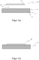
- a fiber preform 10 is initially provided, which at least partially has the later component shape of the fiber composite component to be produced.
- the fiber preform 10 has been formed from a fiber material 11 by placing several layers of fiber materials on top of each other.
- a very simplified component shape is shown. It goes without saying that any complex component shape can be manufactured here.
- pre-impregnated fiber materials 11 were used, so that the matrix material 12 embedding the fiber material 11 is already contained in the fiber preform 10 during the production of the fiber preform 10.
- a monofilament fabric 20 is provided, which also already contains a matrix material 21 and is therefore also pre-impregnated.
- the monofilament fabric 20 has a plurality of fabric threads 22, which are designed as individual filaments.
- step 1b the monofilament fabric 20 is now arranged within an application area 13 of the fiber preform, with a different material being applied later within the application area 13.
- step 1b the monofilament fabric 20 is first arranged in the application area 13, with the matrix material 12 of the fiber preform 10 and the matrix material 21 of the monofilament fabric 20 coming into contact with one another and possibly mixing with one another in the boundary area (boundary layer).
- the matrix material 12 of the fiber preform 10 and the matrix material 21 of the monofilament fabric 20 are then at least partially cured, whereby the monofilament fabric 20 is cohesively connected to the fiber preform 10 or the fiber composite component.
- the monofilament fabric 20 is torn perpendicular to the fiber preform 10 or the fiber composite component, so that the cohesive connection between the monofilament fabric 20 and the fiber composite component or the fiber preform 10 is cohesively broken within the application area 13.
- the resulting rough surface 14 within the application area 13 has a high surface energy, the use of a monofilament fabric in particular preventing reinforcing fibers of the fiber material 11 of the fiber preform 10 from being torn out and damaged.
- the proportion of the cohesively broken surface within the application area 13 can be adjusted by the open areas or the mesh size of the monofilament fabric 20, whereby it must be taken into account that the monofilament fabric as a tear-off fabric is also removed from the fiber preform 10 after it has been bonded to the fiber preform 10 needs to be done without it tearing.
- the actual material 30 is applied within the application area 13, which can be done, for example, using an applicator 31.
- FIG. 2 shows a schematically very simplified section of a monofilament fabric 20, in which the warp threads 23 and the weft thread(s) 24 consist of a single filament.
- the warp threads 23 or the weft threads 24 are not multifilaments and therefore do not have several filaments per se. Rather, each warp thread 23 or weft thread 24 consists of a single filament.
- a stitch 25 is delimited by the respective warp thread or weft thread, the open area 26 of a stitch 25 being the area that is geometrically defined by the mesh width or mesh height.
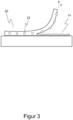
- Figure 3 shows schematically the process of tearing the monofilament fabric 20 from the fiber preform 10. As can be seen, the cohesive connection between the individual filaments 22 is broken coherently, so that a cohesive surface 14 results here.
Landscapes
- Engineering & Computer Science (AREA)
- Mechanical Engineering (AREA)
- Chemical & Material Sciences (AREA)
- Composite Materials (AREA)
- Reinforced Plastic Materials (AREA)
- Woven Fabrics (AREA)
- Treatments For Attaching Organic Compounds To Fibrous Goods (AREA)
Description
- Die Erfindung betrifft ein Verfahren zum Applizieren eines Werkstoffes auf ein Faserverbundbauteil innerhalb eines Applikationsbereiches des Faserverbundbauteils, wobei das Faserverbundbauteil aus einem Faserverbundwerkstoff aufweisend ein Fasermaterial und ein Matrixmaterial hergestellt wird. Die Erfindung betrifft ebenso eine entsprechende Verwendung hierzu.
- Aufgrund ihrer gewichtsspezifischen Festigkeit und Steifigkeit sind Faserverbundwerkstoffe bei der Herstellung von jedweden Bauteilen kaum mehr wegzudenken. Faserverbundwerkstoffe weisen dabei hauptsächlich zwei wesentliche Bestandteile auf, nämlich zum einen ein Fasermaterial und zum anderen ein Matrixmaterial. Bei der Herstellung von Faserverbundbauteilen aus einem solchen Faserverbundwerkstoff wird dabei in der Regel das Fasermaterial in die entsprechende spätere Bauteilform gebracht und dann das das Fasermaterial einbettende Matrixmaterial ausgehärtet. Das Aushärten geschieht in den allermeisten Fällen durch Temperatur- und ggf. Druckbeaufschlagung, wobei durch das Aushärten die lasttragenden Fasern des Fasermaterials in ihre vorbestimmte Richtung gezwungen werden und dabei zusammen mit dem ausgehärteten Matrixmaterial eine integrale Einheit zur Lastabtragung bilden.
- Das Matrixmaterial, welches das Fasermaterial des Faserverbundwerkstoffes entsprechend einbettet, kann dabei bereits in dem Fasermaterial enthalten sein (sogenannte Prepregs) oder später in eine sogenannte Faserpreform, die aus trockenen Fasermaterialien aufgebaut wurde, infundiert werden. Eine Faserpreform stellt dabei eine Art Vorbauteil dar, das aus dem Fasermaterial des Faserverbundwerkstoffes gebildet und dabei zumindest teilweise die spätere Bauteilform des herzustellenden Faserverbundbauteils erhält. Durch das Aushärten des Matrixmaterials, welches in dem Fasermaterial der Faserpreform eingebettet ist, kann so das Faserverbundbauteil hergestellt werden. Die Faserpreform kann demzufolge sowohl aus trockenem Fasermaterial als auch aus vorimprägnierten Fasermaterialien eines Faserverbundwerkstoffes hergestellt werden.
- Faserverbundbauteile weisen bei der Herstellung einige Nachteile gegenüber isotropen Werkstoffen auf, da die Bauteilform eines Faserverbundbauteils in der Regel durch entsprechende Formwerkzeuge gebildet werden muss, welche eine Art Negativabdruck des späteren Bauteils darstellen. Daher werden nicht selten komplexe Faserverbundbauteile aus verschiedenen Bauelementen, die entweder aus Faserverbundwerkstoffen hergestellt wurden oder aus isotropen Werkstoffen zusammengesetzt werden, miteinander verklebt, um die komplexe Geometrie herstellen zu können.
- Auch die Reparatur von Faserverbundbauteilen kann bei lokalen Beschädigungen durch Kleben von Reparaturpatches erfolgen, indem zunächst an der beschädigten Stelle das Fasermaterial und Matrixmaterial entfernt und so die beschädigte Stelle vorbereitet wird und anschließend dann ein Reparaturpatch eingeklebt wird, sodass der durch den Reparaturvorgang gebildete Freiraum durch den Reparaturpatch ausgefüllt wird. Ein derartiges Kleben, bei dem mindestens einer der Fügepartner ein Faserverbundbauteil aus einem Faserverbundwerkstoff ist, ist dabei nicht ganz unkritisch hinsichtlich der Zertifizierung und Validierung. So müssen gerade im Bereich der Luft- und Raumfahrt hohe Maßstäbe an eine derartige Klebverbindung gestellt werden, um insbesondere auch bei sicherheitskritischen Bauteilen den Anforderungen an die Sicherheit zu genügen. Es ist daher von besonderem Interesse, derartige Klebverbindungen prozesssicher auszuführen.
- Oftmals werden solche Faserverbundbauteile auch durch Lackierungen und Beschichtungen veredelt, so dass derartige Werkstoffe, die auf ein solches fertig hergestelltes Faserverbundbauteil appliziert werden, prozesssicher aufgebracht und auf der Oberfläche eines solchen Faserverbundbauteils sicher halten müssen. Dabei besteht grundsätzlich das Bedürfnis, dass derartige Beschichtungen auch unter gegebenen Stressbedingungen sicher an der Oberfläche des Faserverbundbauteils haften.
- Aus der nachveröffentlichten
DE 10 2017 113 430.1 ist ein Verfahren zum Prüfen einer Fügeoberfläche eines Faserverbundbauteils sowie ein Verfahren zum Verkleben bekannt, indem ein Prüfgewebe mit einer Klebstoffgrundierung auf das Faserverbundbauteil aufgeklebt und ausgehärtet und anschließend abgerissen wird, wobei die Fügeoberfläche qualitativ hinsichtlich des Bruchbildes analysiert wird. Außerdem lässt sich auch ein derartiges Bruchbild, das durch die Klebstoffgrundierung gebildet wurde, durch Auftragen eines Klebwerkstoffes und Fügen mit einem weiteren Bauteil eine Klebverbindung herstellen. - Es hat sich allerdings gezeigt, dass die zusätzliche Klebstoffgrundierung den gesamten Herstellungsprozess verkomplizieren kann. Es hat sich außerdem gezeigt, dass die in der Praxis oftmals verwendeten Multifilamentgewebe als Abreißgewebe für ein derartiges Verfahren bei bestimmten zu applizierenden Werkstoffen nicht geeignet sind. Denn einerseits soll durch das Abreißen des Gewebes eine saubere, aktivierte Oberfläche erzeugt werden, während andererseits das Gewebe möglichst ohne hohen Kraftaufwand händisch abgezogen werden soll, wobei das Bauteil dabei nicht beschädigt werden darf. Um eine besonders adhäsionsfähige Oberfläche zu erzeugen, müssen bei polymeren Matrixwerkstoffen chemische Ketten des Matrixwerkstoffes aufgebrochen werden. Dies gelingt dadurch, dass mit dem Gewebe ein Teil des darunterliegenden Matrixmaterials entfernt wird. Um Matrixmaterial herauszubrechen, wird jedoch ein erhöhter Kraftaufwand benötigt und die Gefahr einer Beschädigung der Faserverbundstruktur, insbesondere der Verstärkungsfasern, steigt dadurch deutlich an.
- Bei der Verwendung eines Multifilamentgewebes als Abreißgewebe, die zum Zwecke des leichten Ablösens sehr dicht gewoben und keine oder nur sehr geringe Freiräume zwischen den Schuss- und Kettfäden aufweisen, entsteht nach dem Abreißvorgang daher meist eine völlig glatte Oberfläche, welche lediglich eine wellige Topologie durch den Abdruck der Gewebefäden aufweist. Eine umfangreiche chemische Aktivierung findet jedoch in den seltensten Fällen statt. Hierzu kommt, dass auf der generierten Oberfläche Rückstände der Fasern oder von Stoffen, welche sich auf den Fasern befunden haben, zurückbleiben können. Somit kann keine gesicherte Aussage getroffen werden, ob auf der durch dieses Verfahren erzeugten Oberfläche sicher geklebt oder lackiert werden kann. Aufwendige Kontrollen, Nacharbeit durch Schleifen oder Strahlen und ein hoher Aufwand bei der Qualitätssicherung sind demzufolge notwendig.
- Aus der
US 7,736,452 B2 ist ein Verfahren zum zerstörungsfreien Überprüfen einer Klebverbindung bei der Reparatur von Faserverbundbauteilen bekannt, wobei hier die Überprüfung der Klebverbindung indirekt erfolgt. Die beschädigte Stelle an dem Faserverbundbauteil wird in einem ersten Schritt repariert und ein entsprechendes eingeklebtes Reparaturpatch verwendet. Anschließend wird in der näheren Umgebung der reparierten Stelle ein Testpatch, welches die gleichen Eigenschaften und das gleiche Material aufweist, wie das Reparaturpatch, aufgeklebt und nach dem Aushärten der Klebverbindung mit einer entsprechenden Kraft belastet. Hält der Testpatch der derart aufgebrachten Kraft stand, so wird von der Haltbarkeit der reparierten Stelle ausgegangen. - Aus der
US 2008/0011075 A1 ist ein Verfahren zur Qualitätskontrolle eines Faserverbundbauteils und einer möglichen Klebverbindung bekannt, wobei hier eine metallische Struktur auf die Oberfläche des Faserverbundbauteils aufgeklebt wird. Die metallische Struktur weist dabei eine Sollbruchstelle auf. Nach dem Aushärten der Klebverbindung wird die metallische Struktur nun mit einer Kraft beaufschlagt, wobei von einer wirksamen Klebverbindung mit der Oberfläche des Faserverbundbauteils dann ausgegangen wird, wenn zunächst die Sollbruchstelle bricht. Bricht anstelle der Sollbruchstelle jedoch die Klebverbindung, so war diese nicht fehlerfrei. - Die Forumsdiskussion Reefmagnet: "Peel ply... how difficult / easy...", 19. November 2014 (2014-11-19), Gefunden im Internet: URL: http://www.cruisersforum.com/forums/f55/peel-ply -how-difficult-easy-136700.html (abgerufen am 25. Juli 2019) beschäftigt sich mit der Vorbehandlung von Oberflächen. Hierfür wird ein mit einem Epoxidharz getränktes Abreißtextil (peel ply) vorgeschlagen, was jedoch auf bereits bestehende, fertige Bauteile aufgeklebt werden soll. Nach dem Abreißen dieses Abreißtextils soll die dadurch entstandene Oberfläche für eine weitere Behandlung entsprechend vorbereitet sein.
- Die
US 4,902,215 offenbart eine Fließhilfe in einem Infusionsprozess bei der Herstellung von Faserverbundbauteilen. Das Dokument zeigt dabei einen klassischen Infusionsprozess, bei dem ein Gewebe zwischen dem herzustellenden Bauteil und einer Fließ- und Verteilschicht für das Matrixmaterial angeordnet ist. Das Gewebe wird dabei zusammen mit dem Bauteil ausgehärtet und zu einem späteren Zeitpunkt von dem hergestellten Bauteil abgeschält. - Die
GB 2 360 483 A US 4,902,215 diese Verteilschicht nicht als vorbereitende Maßnahme für das Applizieren zusätzlicher Werkstoffe nach dem Herstellen des Bauteils dient. - Es ist demzufolge Aufgabe der vorliegenden Erfindung ein verbessertes Verfahren zum Applizieren eines Werkstoffes anzugeben, mit dem die Oberfläche des Faserverbundbauteils so vorbereitet werden kann, dass ein Anhaften des Werkstoffes unter den gegebenen Prozessparametern gewährleistet werden kann.
- Die Aufgabe wird mit dem Verfahren gemäß Anspruch 1 erfindungsgemäß gelöst. Gemäß Anspruch 1 wird ein Verfahren zum Applizieren eines Werkstoffes auf ein Faserverbundbauteil innerhalb eines Applikationsbereiches des Faserverbundbauteils vorgeschlagen, wobei das Faserverbundbauteil aus einem Faserverbundwerkstoff aufweisend ein Fasermaterial und ein Matrixmaterial hergestellt wird. Der zu applizierende Werkstoff kann dabei beispielsweise ein Klebstoff sein, um das Faserverbundbauteil mit einem anderen Bauelement zu fügen. Der Werkstoff kann aber auch der Beschichtung des Faserverbundbauteils dienen, beispielsweise in Form von Lacken. Unter dem Applizieren eines Werkstoffes auf ein Faserverbundbauteil wird dabei verstanden, dass ein Werkstoff stoffschlüssig mit dem Faserverbundbauteil verbunden wird, bspw. ein dem Faserverbundwerkstoff fremder oder anderer Werkstoff, der kein Faserverbundwerkstoff ist, so dass der applizierte Werkstoff stoffschlüssig an dem Faserverbundbauteil hält. Das Applizieren des Werkstoffes soll dabei insbesondere nach dem vollständigen Aushärten des das Fasermaterial einbettenden Matrixmaterials erfolgen. Denkbar ist aber auch, dass das Applizieren bereits zu einem Zeitpunkt erfolgt, zu dem das Matrixmaterial noch nicht vollständig ausgehärtet ist, z.B. durch eine nicht vollständig abgelaufene Härtungsreaktion oder durch ein speziell angepasstes Harz-Härter-Verhältnis in dem das Fasermaterial einbettenden Matrixmaterials.
- Erfindungsgemäß wird dabei zumindest ein Monofilamentgewebe bereitgestellt, bei dem mehrere oder alle Fäden jeweils aus einem Einzelfilament bestehen. Ein derartiges Monofilamentgewebe weist somit Fäden (Schussfaden, Kettfaden) auf, die nicht wie bei einem Multifilamentgewebe jeweils aus einer Mehrzahl von Einzelfilamenten bestehen, sondern bei dem die einzelnen Fäden an sich ein einzelnes Filament darstellen. Ein derartiger Faden eines Monofilamentgewebes weist demzufolge nicht eine Mehrzahl von Einzelfilamenten auf, sondern wird ausschließlich aus einem Einzelfilament gebildet. Üblicherweise werden die einzelnen Fäden bzw. Einzelfilamente in einem einzigen Verarbeitungsschritt verarbeitet.
- Ein derartiges Monofilamentgewebe wird nun in Form eines Abreißgewebes auf die Faserpreform im Applikationsbereich angeordnet. Die Faserpreform wird dabei aus dem Fasermaterial des Faserverbundwerkstoffes gebildet und kann insbesondere aus trockenen oder vorimprägnierten Fasermaterialien gebildet werden. Das Monofilamentgewebe im Applikationsbereich dient später dazu, die Oberfläche innerhalb des Applikationsbereiches dahingehend vorzubereiten, dass die Oberfläche im Applikationsbereich eine hohe Oberflächenenergie aufweist und somit für das Applizieren des Werkstoffes entsprechend vorbereitet ist.
- Nachdem das Monofilamentgewebe auf das Fasermaterial der Faserpreform im Applikationsbereich angeordnet wurde, wird das das Fasermaterial der Faserpreform einbettende Matrixmaterial sowie ein das Monofilamentgewebe einbettendes Matrixmaterial in einem gemeinsamen Prozessschritt ausgehärtet, um so insbesondere auch das Faserverbundbauteil herzustellen. Dabei kann sowohl für das Fasermaterial der Faserpreform als auch für das Monofilamentgewebe dasselbe Matrixmaterial verwendet werden, so dass für das Monofilamentgewebe das gleiche Matrixmaterial verwendet wird, wie für das Fasermaterial der Faserpreform. Denkbar ist allerdings auch, dass hier unterschiedliche Fasermaterialien verwendet würden, was beispielsweise dann sinnvoll ist, wenn vorimprägnierte Materialien verwendet werden, d.h. das Fasermaterial der Faserpreform und/oder das Monofilamentgewebe sind bereits mit dem jeweiligen Matrixmaterial vorimprägniert.
- Durch das Aushärten der Matrixmaterialien entsteht somit im Grenzbereich zwischen Faserpreform und Monofilamentgewebe eine feste Verbindung, wodurch das Monofilamentgewebe zunächst stoffschlüssig mit dem Faserverbundbauteil im Applikationsbereich verbunden wird. Nachdem das Matrixmaterial der Faserpreform und das Matrixmaterial des Monofilamentgewebes somit zumindest teilweise ausgehärtet ist, d.h. zumindest eine Teilreaktion hinsichtlich der Polyreaktion oder Polymerisation stattgefunden hat und somit das Monofilamentgewebe stoffschlüssig an die Faserpreform angefügt wurde, wird das mit der Faserpreform stoffschlüssig verbundene Monofilamentgewebe abgerissen, wodurch das Matrixmaterial im Applikationsbereich insbesondere kohäsiv gebrochen wird. Kohäsiv gebrochen bedeutet, dass das Matrixmaterial in sich selbst gebrochen ist, d.h. beim Bruch geht ein Riss durch das Material. Die so entstandene Oberfläche ist besonders erwünscht und erzeugt dabei eine hohe Oberflächenenergie, an der andere Werkstoffe besonders gut anhaften und die gut benetzbar ist.
- Anschließend wird der entsprechende Werkstoff innerhalb des Applikationsbereiches nach dem Abreißen des Monofilamentgewebes appliziert. Es wurde bei der vorliegenden Erfindung vorteilhafterweise erkannt, dass durch die Verwendung eines Monofilamentgewebes als Abreißgewebe zur Vorbereitung einer Applikationsoberfläche erreicht werden kann, dass trotz hohem Anteil an Kohäsionsbruch kaum Laminatschäden beim Entfernen des Abreißgewebes auftreten. Aus der Praxis bekannte Multifilamentgewebe führen trotz sehr geringem Anteil an Kohäsionsbruch häufig zu Laminatschäden. In Multifilamentgeweben kommt es häufig zu einem großflächigen Kontakt und zum teilweisen Ineinandergleiten zwischen Verstärkungsfasern und der Vielzahl von benachbarten Filamenten des Abreißgewebes. Dies führt teilweise zum unerwünschten Herauslösen von Verstärkungsfasern beim Entfernen des Abreißgewebes. Die Verwendung eines Monofilamentgewebes hingegen erzeugt diese Nachteile nicht und bieten aufgrund ihrer in der Regel vielfach größeren Filamentdurchmesser und den freiliegenden Filamenten (ohne direkte Nachbarn) wenig Möglichkeit zum Mitreißen von Verstärkungsfasern. Der Kohäsivbruch wird in der Regel im Bereich des dünnsten Querschnitts der Gewebeöffnung erzeugt und ist somit räumlich von den Verstärkungsfasern getrennt, wobei die beim Bruch anliegende mechanische Spannung im Bereich der entstehenden Bruchfläche aufgrund der Kerbwirkung größer ist, als auf der Ebene der Verstärkungsfasern.
- Es wurde bei der vorliegenden Erfindung vorteilhafterweise weiterhin erkannt, dass der Einsatz von Monofilamentgeweben zu einem rückstandsfreien Herauslösen des Abreißgewebes führt. Dies ist ebenfalls der freiliegenden Filamente und ihrer größeren Durchmesser geschuldet. Im Falle von Multifilamentgeweben bleiben häufig Teile oder Bruchstücke der Filamente auf der Bauteiloberfläche zurück, welche für einen nachfolgenden Prozess zum stoffschlüssigen Fügen besonders nachteilhaft sind.
- Des Weiteren führt die Verwendung eines Monofilamentgewebes als Abreißgewebe zu einer sehr starken Oberflächenvergrößerung und Oberflächentexturierung. Die vergrößerte Oberfläche ist dabei besonders vorteilhaft für nachfolgende Beschichtungsoperationen, da mehr Kontaktfläche zur Ausbildung von Adhäsionskräften zur Verfügung steht. Durch die Oberflächentexturierung kann sich zusätzlich ein Formschluss ausbilden, sodass insbesondere Beschichtungen und Klebstoffe besonders gut an derartig vorbereiteten Oberflächen haften.
- Erfindungsgemäß ist vorgesehen, dass ein Monofilamentgewebe bereitgestellt wird, bei dem die Summe aller offenen Flächen der Maschen des Monofilamentgewebes mindestens 30 % der gesamten Grundfläche des Monofilamentgewebes entspricht.
- Hierdurch wird erreicht, dass innerhalb der offenen Flächen einer Masche beim Abreißen des Monofilamentgewebes eine kohäsive Bruchfläche entsteht, was durch die Ausführung des Monofilamentgewebes aus Einzelfilamenten besonders begünstigt wird. Diese kohäsiven Bruchflächen sind dabei besonders wünschenswert, da sie eine besonders hohe Oberflächenenergie aufweisen.
- Bei dem Monofilamentgewebe kann es sich beispielsweise um eine Leinwandbindung, Köperbindung, Atlasbindung, Tressengewebe, Drehergewebe und/oder triaxiales Gewebe handeln.
- Bei dem Faserverbundbauteil handelt es sich nicht um einen Prüfkörper, der lediglich zu Test- und Überprüfungszwecken hergestellt wird und danach keine weitere Verwendung findet. Vielmehr handelt es sich bei dem Faserverbundbauteil im Sinne der vorliegenden Erfindung um ein reales Bauteil, dass nach der Herstellung einen entsprechenden vorgesehenen Verwendungszweck hat.
- In einer weiteren vorteilhaften Ausführungsform ist das Monofilamentgewebe derart ausgebildet, dass ein oder mehrere Schussfäden und/oder ein oder mehrere Kettfäden jeweils aus einem Einzelfilament bestehen, vorteilhafterweise sind jedoch sämtliche Schussfäden und sämtliche Kettfäden als Einzelfilamente ausgebildet.
- In einer besonders vorteilhaften Ausführungsform wird ein Monofilamentgewebe bereitgestellt, bei dem die Summe aller offenen Flächen der Maschen des Monofilamentgewebes mindestens 50 %, vorzugsweise zwischen 50% und 70% der gesamten Grundfläche des Monofilamentgewebes entspricht. Die offenen Flächen einer Masche des Monofilamentgewebes definiert sich dabei aus der Ausdehnung der Maschen in eine erste Dimension und in eine zweite flächige Dimension (meist quadratisch), wobei die Summe der offenen Flächen aller Maschen mindestens 30 % der Gesamtfläche des gesamten Monofilamentgewebes entspricht.
- Daher ist es ebenso besonders vorteilhaft, wenn ein Monofilamentgewebe bereitgestellt wird, welches nach dem Abreißen von dem Faserverbundbauteil eine kohäsiv gebrochene Fläche hat, die mindestens 30 %, vorzugsweise mindestens 50%, besonders vorzugsweise zwischen 50% und 70% der geometrischen Fläche des Applikationsbereiches entspricht. Das heißt, die Summe aller kohäsiv gebrochenen Flächen innerhalb des Applikationsbereiches entspricht in Summe mindestens 30 %, vorzugweise mindestens 50 %, besonders vorzugsweise zwischen 50% und 70% der gesamten Fläche des Applikationsbereiches.
- In einer weiteren vorteilhaften Ausführungsform wird das Monofilamentgewebe mit Einzelfilamenten aus Polyester, Polyethylen, Polyethylenterephthalat, Polyamid und/oder Metall, insbesondere Stahl, bereitgestellt.
- So hat es sich gezeigt, dass einem Abreißgewebe aus Stahl, insbesondere rostfreiem Stahl mit bspw. einer Chromoxidschicht, die zu verklebende Oberfläche des Bauteils besonders gut auf eine Klebung vorbereitet wird, da der Anteil des Kohäsivbruches besonders hoch ist und auf der Oberfläche kaum Rückstände verbleiben, die eine Klebung negativ beeinflussen. Dadurch können auch weniger robuste Klebstoffe auf der Faseroberfläche sehr gut und dauerhaft anhaften. Hintergrund ist vermutlich, dass zwischen der inerten Chromoxidschicht an der Oberfläche von Gewebe aus rostfreiem Stahl und dem Matrixmaterial keine für das Kleben abträgliche Interaktion stattfindet. Bei der Verwendung von Abreißgeweben aus polymeren Werkstoffen können hingegen Rückstände auf der Bauteiloberfläche verbleiben, die eine Anhaftung des Klebstoffes negativ beeinträchtigen.
- Des Weiteren ist es denkbar, dass als Werkstoff ein Klebstoff appliziert und ein Bauelement mittels des applizierten Klebstoffes an das Faserverbundbauteil klebend gefügt wird. Ein solcher Klebstoff kann dabei separat in den Applikationsbereich auf die kohäsiv gebrochene Oberfläche aufgetragen werden, wobei anschließend dann das zu fügende Bauelement angeklebt wird. Denkbar ist aber auch, dass Klebstoff und anzufügendes Bauelement in einem gemeinsamen Prozessschritt auf die kohäsiv gebrochene Oberfläche im Applikationsbereich angefügt wird. Des Weiteren ist es denkbar, dass als Werkstoff eine Beschichtung appliziert wird, wie beispielsweise Lacke.
- In einer weiteren vorteilhaften Ausführungsform weisen ein oder mehrere Fäden, vorzugsweise alle Fäden bzw. Einzelfilamente des Monofilamentgewebes eine funktionale Beschichtung auf, wobei zumindest ein Teil des Beschichtungsstoffes nach dem Abreißen auf dem Faserverbundbauteil verbleibt (bspw. in den Abdruckbereichen der Einzelfilamente) und weitere Funktionen übernimmt, bspw. als Rissstopper oder als Haftvermittler). Die funktionale Beschichtung geht eine feste Verbindung mit dem Matrixmaterial des Bauteils ein und löst sich von der Faser ab, sobald das Gewebe abgerissen wird.
- Die Aufgabe wird im Übrigen auch mit dem Verwendungsanspruch 11 gelöst, wobei hier eine Verwendung eines Monofilamentgewebes, bei dem mehrere oder alle Fäden jeweils aus einem Einzelfilament bestehen, als Abreißgewebe beim Applizieren eines Werkstoffes auf ein Faserverbundwerkstoff gemäß dem vorstehend beschriebenen Verfahren beansprucht wird.
- Die Erfindung wird anhand der beigefügten Figuren beispielhaft näher erläutert. Es zeigen:
- Figur 1a-1d -
- Schematische Darstellung der wesentlichen Verfahrensschritte des erfindungsgemäßen Verfahrens;
- Figur 2 -
- Schematische Darstellung eines Monofilamentgewebes;
- Figur 3 -
- Schematisch-Makroskopische Darstellung eines Bruchbildes.
- In den
Figuren 1a-1d wird ein möglicher Verlauf des erfindungsgemäßen Verfahrens zum Applizieren eines Werkstoffes dargestellt. So wird im ersten Schritt 1a zunächst eine Faserpreform 10 bereitgestellt, die zumindest teilweise die spätere Bauteilform des herzustellenden Faserverbundbauteils aufweist. Die Faserpreform 10 ist dabei aus einem Fasermaterial 11 gebildet worden, indem mehrere Lagen Fasermaterialien übereinandergelegt wurden. Im Beispiel derFigur 1a ist eine sehr stark vereinfachte Bauteilform dargestellt. Es ist selbstverständlich, dass hier jede beliebige komplexe Bauteilform hergestellt werden kann. - Des Weiteren wurden vorimprägnierte Fasermaterialien 11 verwendet, so dass bereits bei der Herstellung der Faserpreform 10 das das Fasermaterial 11 einbettende Matrixmaterial 12 in der Faserpreform 10 enthalten ist.
- Des Weiteren wird ein Monofilamentgewebe 20 bereitgestellt, das ebenfalls bereits ein Matrixmaterial 21 enthält und somit ebenfalls vorimprägniert ist. Das Monofilamentgewebe 20 weist eine Mehrzahl von Gewebefäden 22 auf, die als Einzelfilamente ausgebildet sind.
- Im nächsten Verfahrensschritt 1b wird nun das Monofilamentgewebe 20 innerhalb eines Applikationsbereiches 13 der Faserpreform angeordnet, wobei innerhalb des Applikationsbereiches 13 später ein anderer Werkstoff appliziert werden soll. Im Schritt 1b wird aber nun zunächst in den Applikationsbereich 13 das Monofilamentgewebe 20 angeordnet, wobei dabei das Matrixmaterial 12 der Faserpreform 10 und das Matrixmaterial 21 des Monofilamentgewebes 20 miteinander in Berührung kommen und ggf. sich miteinander im Grenzbereich (Grenzschicht) vermischen.
- Anschließend wird das Matrixmaterial 12 der Faserpreform 10 und das Matrixmaterial 21 des Monofilamentgewebes 20 zumindest teilweise ausgehärtet, wobei hierdurch das Monofilamentgewebe 20 stoffschlüssig mit der Faserpreform 10 bzw. dem Faserverbundbauteil verbunden wird.
- Anschließend wird, wie in
Figur 1c gezeigt, das Monofilamentgewebe 20 senkrecht zu der Faserpreform 10 bzw. des Faserverbundbauteils abgerissen, so dass die stoffschlüssige Verbindung zwischen dem Monofilamentgewebe 20 und dem Faserverbundbauteil bzw. der Faserpreform 10 innerhalb des Applikationsbereiches 13 kohäsiv aufgebrochen wird. Die dabei entstandene raue Oberfläche 14 innerhalb des Applikationsbereiches 13 weist dabei eine hohe Oberflächenenergie auf, wobei durch die Verwendung eines Monofilamentgewebes insbesondere verhindert wird, dass Verstärkungsfasern des Fasermaterials 11 der Faserpreform 10 mit herausgerissen und beschädigt werden. - Der Anteil der kohäsiv gebrochenen Oberfläche innerhalb des Applikationsbereiches 13 kann dabei durch die offenen Flächen bzw. die Maschenweite des Monofilamentgewebes 20 eingestellt werden, wobei hierbei berücksichtigt werden muss, dass das Monofilamentgewebe als Abreißgewebe nach dem stoffschlüssigen Verbinden mit der Faserpreform 10 auch von dieser noch entfernt werden muss, ohne dass es hierbei reißt. Anschließend wird im Schritt 1d der eigentliche Werkstoff 30 innerhalb des Applikationsbereiches 13 appliziert, was beispielsweise mithilfe eines Applikators 31 erfolgen kann.
-
Figur 2 zeigt schematisch stark vereinfacht einen Ausschnitt aus einem Monofilamentgewebe 20, bei dem die Kettfäden 23 und der oder die Schussfäden 24 aus einem Einzelfilament bestehen. Das bedeutet, dass die Kettfäden 23 bzw. die Schussfäden 24 keine Multifilamente sind und somit nicht mehrere Filamente an sich aufweisen. Vielmehr besteht jeder Kettfaden 23 oder Schussfaden 24 aus einem einzelnen Filament. Eine Masche 25 wird dabei durch den jeweiligen Kettfaden bzw. Schussfaden begrenzt, wobei die offene Fläche 26 einer Masche 25 dabei derjenige Bereich ist, der durch die Maschenweite bzw. Maschenhöhe geometrisch definiert wird. - Innerhalb dieser offenen Fläche 26 wird dabei die stoffschlüssige Verbindung zwischen dem Monofilamentgewebe 20 und der Faserpreform bzw. dem Faserverbundbauteil 10 kohäsiv gebrochen, was zu der gewünschten Oberflächenenergie führt.
-
Figur 3 zeigt schematisch den Vorgang des Abreißens des Monofilamentgewebes 20 von der Faserpreform 10. Wie zu erkennen ist, werden zwischen den Einzelfilamenten 22 die stoffschlüssige Verbindung jeweils kohärent gebrochen, so dass sich hier eine kohäsive Oberfläche 14 ergibt. -
- 10 -
- Faserpreform
- 11 -
- Fasermaterial
- 12 -
- Matrixmaterial
- 13 -
- Applikationsbereich
- 14 -
- kohäsiv gebrochene Oberfläche
- 20 -
- Monofilamentgewebe
- 21 -
- Matrixmaterial des Monofilamentgewebes
- 22 -
- Gewebefäden
- 23 -
- Kettfäden
- 24 -
- Schussfäden
- 25 -
- Maschen
- 26 -
- offene Flächen
- 30 -
- zu applizierender Werkstoff
- 31 -
- Applikator
Claims (11)
- Verfahren zum Applizieren eines Werkstoffes auf ein Faserverbundbauteil innerhalb eines Applikationsbereiches (13) des Faserverbundbauteils, wobei das Faserverbundbauteil aus einem Faserverbundwerkstoff aufweisend ein Fasermaterial (11) und ein Matrixmaterial (12) hergestellt wird, dadurch gekennzeichnet, dass das Verfahren die folgenden Schritte umfasst:- Bereitstellen zumindest eines Monofilamentgewebes (20), bei dem mehrere oder alle Fäden jeweils aus einem Einzelfilament bestehen, wobei das Monofilamentgewebe derart bereitgestellt wird, dass die Summe aller offenen Flächen der Maschen des Monofilamentgewebes mindestens 30 % der gesamten Grundfläche des Monofilamentgewebes entspricht,- Anordnen des mindestens einen Monofilamentgewebes (20) auf eine aus dem Fasermaterial (11) des Faserverbundwerkstoffes gebildeten Faserpreform (10) im Applikationsbereich (13),- Aushärten des das Fasermaterial (11) der Faserpreform (10) einbettenden Matrixmaterials (12) des Faserverbundwerkstoffes sowie ein das Monofilamentgewebe (20) einbettendes Matrixmaterial (21) in einem gemeinsamen Prozessschritt, undnachdem das Matrixmaterial (12) der Faserpreform (10) und das Matrixmaterial (21) des Monofilamentgewebes (20) zumindest teilweise ausgehärtet ist,- Abreißen des mit der Faserpreform (10) stoffschlüssig verbundenen Monofilamentgewebes (20), und- Applizieren des Werkstoffes (30) in den Applikationsbereich (13) nach dem Abreißen des Monofilamentgewebes (20).
- Verfahren nach Anspruch 1, dadurch gekennzeichnet, dass das Monofilamentgewebe (20) als Leinwandbindung, Köperbindung, Atlasbindung, Tressengewebe, Drehergewebe und/oder triaxiales Gewebe bereitgestellt wird.
- Verfahren nach Anspruch 1 oder 2, dadurch gekennzeichnet, dass das Monofilamentgewebe (20) derart bereitgestellt wird, dass der oder die Schussfäden (24) und/oder oder die Kettfäden (23) jeweils aus einem Einzelfilamenten bestehen.
- Verfahren nach einem der vorhergehenden Ansprüche, dadurch gekennzeichnet, dass das Monofilamentgewebe (20) derart bereitgestellt wird, dass die Summe aller offenen Flächen (26) der Maschen (25) des Monofilamentgewebes (20) mindestens 50%, vorzugsweise zwischen 50% und 70% der gesamten Grundfläche des Monofilamentgewebes (20) entspricht.
- Verfahren nach einem der vorhergehenden Ansprüche, dadurch gekennzeichnet, dass das Monofilamentgewebe (20) derart bereitgestellt wird, dass die Summe aller kohäsiv gebrochenen Bereiche nach dem Abreißen des Monofilamentgewebes (20) innerhalb des Applikationsbereiches (13) mindestens 30%, vorzugsweise mindestens 50%, besonders vorzugsweise zwischen 50% und 70% der Gesamtfläche des Applikationsbereiches (13) entspricht.
- Verfahren nach einem der vorhergehenden Ansprüche, dadurch gekennzeichnet, dass das Monofilamentgewebe (20) mit Einzelfilamenten aus Polyester, Polyethylen, Polyethylenterephthalat, Polyamid und/oder Metall, insbesondere Stahl, bereitgestellt wird.
- Verfahren nach einem der vorhergehenden Ansprüche, dadurch gekennzeichnet, dass das Matrixmaterial (21), welches das Monofilamentgewebe (20) einbettet, das Matrixmaterial (12) des Faserverbundwerkstoffes ist, welches auch das Fasermaterial (11) der Faserpreform (10) einbettet, oder dass das Matrixmaterial (21), welches das Monofilamentgewebe (20) einbettet, ein von dem Matrixmaterial (12) des Faserverbundwerkstoffes, welches das Fasermaterial (11) der Faserpreform (10) einbettet, verschiedenes Material ist.
- Verfahren nach einem der vorhergehenden Ansprüche, dadurch gekennzeichnet, dass das Fasermaterial (11) und/oder das Monofilamentgewebe (20) mit dem jeweiligen Matrixmaterial (12, 21) vorimprägniert ist oder dass das Matrixmaterial (12) des Faserverbundwerkstoffes in einem Infusionsschritt in das Fasermaterial (11) der Faserpreform (10) infundiert wird.
- Verfahren nach einem der vorhergehenden Ansprüche, dadurch gekennzeichnet, dass als Werkstoff (30) ein Klebstoff appliziert und ein Bauelement mittels des applizierten Klebstoffes an das Faserverbundbauteil klebend gefügt wird und/oder dass als Werkstoff (30) eine Beschichtung appliziert wird.
- Verfahren nach einem der vorhergehenden Ansprüche, dadurch gekennzeichnet, dass das ein oder mehrere Fäden des Monofilamentgewebes eine funktionale Beschichtung aufweisen, wobei zumindest ein Teil des Beschichtungsstoffes nach dem Abreißen auf dem Faserverbundbauteil verbleibt und weitere Funktionen übernimmt.
- Verwendung eines Monofilamentgewebes (20), bei dem mehrere oder alle Fäden jeweils aus einem Einzelfilament bestehen, als Abreißgewebe beim Applizieren eines Werkstoffes (30) auf ein Faserverbundbauteil gemäß dem Verfahren nach einem der vorhergehenden Ansprüche.
Applications Claiming Priority (2)
| Application Number | Priority Date | Filing Date | Title |
|---|---|---|---|
| DE102018111306.4A DE102018111306B4 (de) | 2018-05-11 | 2018-05-11 | Verfahren zum Applizieren eines Werkstoffes auf ein Faserverbundbauteil |
| PCT/EP2019/061961 WO2019215294A1 (de) | 2018-05-11 | 2019-05-09 | Verfahren zum applizieren eines werkstoffes auf ein faserverbundbauteil |
Publications (2)
| Publication Number | Publication Date |
|---|---|
| EP3790730A1 EP3790730A1 (de) | 2021-03-17 |
| EP3790730B1 true EP3790730B1 (de) | 2024-02-07 |
Family
ID=66476655
Family Applications (1)
| Application Number | Title | Priority Date | Filing Date |
|---|---|---|---|
| EP19723107.9A Active EP3790730B1 (de) | 2018-05-11 | 2019-05-09 | Verfahren zum applizieren eines werkstoffes auf ein faserverbundbauteil |
Country Status (5)
| Country | Link |
|---|---|
| US (1) | US11858222B2 (de) |
| EP (1) | EP3790730B1 (de) |
| DE (1) | DE102018111306B4 (de) |
| ES (1) | ES2974027T3 (de) |
| WO (1) | WO2019215294A1 (de) |
Families Citing this family (7)
| Publication number | Priority date | Publication date | Assignee | Title |
|---|---|---|---|---|
| DE102018130330B4 (de) * | 2018-11-29 | 2023-02-09 | Deutsches Zentrum für Luft- und Raumfahrt e.V. | Verfahren zur Herstellung eines Prüfkörpers |
| DE102019121563A1 (de) | 2019-08-09 | 2021-02-11 | Deutsches Zentrum für Luft- und Raumfahrt e.V. | Verfahren zur Herstellung eines Bauteils sowie Bauteil hierzu |
| DE102019121592B3 (de) * | 2019-08-09 | 2020-08-27 | Deutsches Zentrum für Luft- und Raumfahrt e.V. | Verfahren zur Herstellung eines Bauteils sowie Bauteil hierzu |
| DE102020108240A1 (de) | 2020-03-25 | 2021-09-30 | Deutsches Zentrum für Luft- und Raumfahrt e.V. | Verfahren zur Herstellung einer Prüfklebung sowie Bauteil und Vakuumaufbau hierzu |
| DE102021122791A1 (de) | 2021-08-23 | 2023-02-23 | Faserverbund Innovations UG (haftungsbeschränkt) | Preform-Patch und Verfahren zur nachträglichen Verstärkung eines Faserverbundbauteils |
| EP4392239A1 (de) | 2021-08-23 | 2024-07-03 | Faserverbund Innovations UG (haftungsbeschränkt) | Preform-patch und verfahren zur nachträglichen verstärkung eines faserverbundbauteils |
| DE102022105181A1 (de) | 2022-03-04 | 2023-09-07 | Deutsches Zentrum für Luft- und Raumfahrt e.V. | Verfahren zum Applizieren eines Werkstoffes auf ein Faserverbundbauteil |
Family Cites Families (13)
| Publication number | Priority date | Publication date | Assignee | Title |
|---|---|---|---|---|
| DE3527917A1 (de) | 1985-08-03 | 1987-02-12 | Boehler Ag | Federblatt und verfahren zur herstellung desselben |
| US4902215A (en) * | 1988-06-08 | 1990-02-20 | Seemann Iii William H | Plastic transfer molding techniques for the production of fiber reinforced plastic structures |
| GB2360483A (en) * | 2000-03-02 | 2001-09-26 | Slingsby Aviat Ltd | Improvements in the manufacture of resin-impregnated components |
| GB0130853D0 (en) | 2001-12-22 | 2002-02-06 | Bae Systems Plc | Method of forming a bond on or in an aircraft component |
| CA2656276C (en) | 2006-06-30 | 2013-09-17 | Airbus Espana, S.L. | Quality control process for a structural bonded joint |
| JP2009221390A (ja) | 2008-03-18 | 2009-10-01 | Jamco Corp | 複合材連続成形用プリプレグピールプライ |
| DK2285553T3 (da) | 2008-05-16 | 2013-03-18 | Xemc Darwind Bv | Fremgangsmåde til at producere en turbinebladhalvdel og fremgangsmåde til at producere en turbineblad |
| DE102011010384B4 (de) | 2011-02-05 | 2015-06-11 | Premium Aerotec Gmbh | Verfahren zur Herstellung eines Faserverbundbauteils |
| DE102011082664C5 (de) | 2011-09-14 | 2017-08-10 | Senvion Gmbh | Form zur Herstellung eines Steges und Steg für ein Rotorblatt einer Windenergieanlage |
| ES2693221T3 (es) * | 2011-12-30 | 2018-12-10 | Cytec Technology Corp. | Capa despegable |
| FR3025131B1 (fr) * | 2014-09-03 | 2016-09-16 | Airbus Group Sas | Piece composite thermodurcissable pre-polymerisee et procedes de realisation d'une telle piece |
| EP3227363B1 (de) * | 2014-11-03 | 2020-10-07 | Cytec Industries Inc. | Bonding von verbundstoffen |
| DE102017113430A1 (de) | 2017-06-19 | 2018-12-20 | Deutsches Zentrum für Luft- und Raumfahrt e.V. | Verfahren und Vorrichtung zum Überprüfen einer Fügeoberfläche |
-
2018
- 2018-05-11 DE DE102018111306.4A patent/DE102018111306B4/de active Active
-
2019
- 2019-05-09 WO PCT/EP2019/061961 patent/WO2019215294A1/de not_active Ceased
- 2019-05-09 EP EP19723107.9A patent/EP3790730B1/de active Active
- 2019-05-09 US US17/054,263 patent/US11858222B2/en active Active
- 2019-05-09 ES ES19723107T patent/ES2974027T3/es active Active
Also Published As
| Publication number | Publication date |
|---|---|
| DE102018111306B4 (de) | 2022-10-20 |
| US11858222B2 (en) | 2024-01-02 |
| US20210316496A1 (en) | 2021-10-14 |
| DE102018111306A1 (de) | 2019-11-14 |
| ES2974027T3 (es) | 2024-06-25 |
| EP3790730A1 (de) | 2021-03-17 |
| WO2019215294A1 (de) | 2019-11-14 |
Similar Documents
| Publication | Publication Date | Title |
|---|---|---|
| DE102018111306B4 (de) | Verfahren zum Applizieren eines Werkstoffes auf ein Faserverbundbauteil | |
| DE102011004775B4 (de) | Verfahren zum Herstellen einer Verbindung, Verbindung sowie Luft- oder Raumfahrzeug | |
| DE102011014017B4 (de) | Verfahren zur Vorbehandlung eines Faserverbundwerkstoffs | |
| DE102017113430A1 (de) | Verfahren und Vorrichtung zum Überprüfen einer Fügeoberfläche | |
| EP1738895B1 (de) | Gelenk | |
| DE102011056088B4 (de) | Reparaturverfahren | |
| DE2825191A1 (de) | Verfahren zur herstellung eines durch kohlefaeden verstaerkten zahnradmaterials sowie das dabei erhaltene material | |
| DE102018130330B4 (de) | Verfahren zur Herstellung eines Prüfkörpers | |
| EP4010178B1 (de) | Verfahren zum reparieren eines faserverbundbauteils | |
| EP3527641B1 (de) | Klebefilm sowie anordnung und verfahren zur überprüfung einer klebeanbindung | |
| DE102010003356B4 (de) | Verfahren zur Herstellung eines Bauteils aus einem Verbundmaterial und Komponente für ein Bauteil aus einem Verbundmaterial | |
| DE102008051380B4 (de) | Verfahren zur Reparatur von faserverstärkten Kunststoffbauteilen | |
| WO2009112017A2 (de) | Verfahren zur herstellung eines rotorblattes für eine windkraftanlage sowie ein nach diesem verfahren hergestelltes rotorblatt | |
| DE102011010384B4 (de) | Verfahren zur Herstellung eines Faserverbundbauteils | |
| DE102019121563A1 (de) | Verfahren zur Herstellung eines Bauteils sowie Bauteil hierzu | |
| EP3892451B1 (de) | Herstellungsverfahren zum herstellen eines endlosfaserverstärkten bauteils | |
| WO2005102697A1 (de) | Verbundbauteil für eine fahrzeugkarosserie, insbesondere ein fahrzeugdach, sowie herstellungsverfahren dafür | |
| DE10323132B4 (de) | Verstellbare Leitschaufel und Verfahren zur Herstellung derselben | |
| DE102018131797A1 (de) | Verfahren und Vorrichtung zum Überprüfen einer Fügeoberfläche | |
| DE102014200923A1 (de) | Verfahren zum Kennzeichnen von textilen Faserhalbzeugen | |
| DE102019121592B3 (de) | Verfahren zur Herstellung eines Bauteils sowie Bauteil hierzu | |
| DE102014005146A1 (de) | Verfahren zum Bereitstellen von Abstandshaltern | |
| EP4238747A1 (de) | Verfahren zum applizieren eines werkstoffes auf ein faserverbundbauteil | |
| DE102016200958A1 (de) | Eindreh-Insert zum Integrieren in ein Faserhalbzeug | |
| DE102020128398A1 (de) | Verbundbauteilsystem, Verwendung eines Verbundbauteilsystems sowie Verfahren zum Reparieren eines Verbundbauteilsystems |
Legal Events
| Date | Code | Title | Description |
|---|---|---|---|
| STAA | Information on the status of an ep patent application or granted ep patent |
Free format text: STATUS: UNKNOWN |
|
| STAA | Information on the status of an ep patent application or granted ep patent |
Free format text: STATUS: THE INTERNATIONAL PUBLICATION HAS BEEN MADE |
|
| PUAI | Public reference made under article 153(3) epc to a published international application that has entered the european phase |
Free format text: ORIGINAL CODE: 0009012 |
|
| STAA | Information on the status of an ep patent application or granted ep patent |
Free format text: STATUS: REQUEST FOR EXAMINATION WAS MADE |
|
| 17P | Request for examination filed |
Effective date: 20201029 |
|
| AK | Designated contracting states |
Kind code of ref document: A1 Designated state(s): AL AT BE BG CH CY CZ DE DK EE ES FI FR GB GR HR HU IE IS IT LI LT LU LV MC MK MT NL NO PL PT RO RS SE SI SK SM TR |
|
| AX | Request for extension of the european patent |
Extension state: BA ME |
|
| DAV | Request for validation of the european patent (deleted) | ||
| DAX | Request for extension of the european patent (deleted) | ||
| GRAP | Despatch of communication of intention to grant a patent |
Free format text: ORIGINAL CODE: EPIDOSNIGR1 |
|
| STAA | Information on the status of an ep patent application or granted ep patent |
Free format text: STATUS: GRANT OF PATENT IS INTENDED |
|
| INTG | Intention to grant announced |
Effective date: 20230220 |
|
| GRAJ | Information related to disapproval of communication of intention to grant by the applicant or resumption of examination proceedings by the epo deleted |
Free format text: ORIGINAL CODE: EPIDOSDIGR1 |
|
| STAA | Information on the status of an ep patent application or granted ep patent |
Free format text: STATUS: REQUEST FOR EXAMINATION WAS MADE |
|
| INTC | Intention to grant announced (deleted) | ||
| GRAP | Despatch of communication of intention to grant a patent |
Free format text: ORIGINAL CODE: EPIDOSNIGR1 |
|
| STAA | Information on the status of an ep patent application or granted ep patent |
Free format text: STATUS: GRANT OF PATENT IS INTENDED |
|
| INTG | Intention to grant announced |
Effective date: 20230821 |
|
| GRAS | Grant fee paid |
Free format text: ORIGINAL CODE: EPIDOSNIGR3 |
|
| GRAA | (expected) grant |
Free format text: ORIGINAL CODE: 0009210 |
|
| STAA | Information on the status of an ep patent application or granted ep patent |
Free format text: STATUS: THE PATENT HAS BEEN GRANTED |
|
| AK | Designated contracting states |
Kind code of ref document: B1 Designated state(s): AL AT BE BG CH CY CZ DE DK EE ES FI FR GB GR HR HU IE IS IT LI LT LU LV MC MK MT NL NO PL PT RO RS SE SI SK SM TR |
|
| REG | Reference to a national code |
Ref country code: GB Ref legal event code: FG4D Free format text: NOT ENGLISH |
|
| REG | Reference to a national code |
Ref country code: DE Ref legal event code: R081 Ref document number: 502019010540 Country of ref document: DE Owner name: DEUTSCHES ZENTRUM FUER LUFT- UND RAUMFAHRT E.V, DE Free format text: FORMER OWNER: ANMELDERANGABEN UNKLAR / UNVOLLSTAENDIG, 80297 MUENCHEN, DE |
|
| REG | Reference to a national code |
Ref country code: CH Ref legal event code: EP |
|
| REG | Reference to a national code |
Ref country code: IE Ref legal event code: FG4D Free format text: LANGUAGE OF EP DOCUMENT: GERMAN |
|
| REG | Reference to a national code |
Ref country code: DE Ref legal event code: R096 Ref document number: 502019010540 Country of ref document: DE |
|
| REG | Reference to a national code |
Ref country code: LT Ref legal event code: MG9D |
|
| REG | Reference to a national code |
Ref country code: NL Ref legal event code: MP Effective date: 20240207 |
|
| REG | Reference to a national code |
Ref country code: ES Ref legal event code: FG2A Ref document number: 2974027 Country of ref document: ES Kind code of ref document: T3 Effective date: 20240625 |
|
| PG25 | Lapsed in a contracting state [announced via postgrant information from national office to epo] |
Ref country code: IS Free format text: LAPSE BECAUSE OF FAILURE TO SUBMIT A TRANSLATION OF THE DESCRIPTION OR TO PAY THE FEE WITHIN THE PRESCRIBED TIME-LIMIT Effective date: 20240607 |
|
| PG25 | Lapsed in a contracting state [announced via postgrant information from national office to epo] |
Ref country code: LT Free format text: LAPSE BECAUSE OF FAILURE TO SUBMIT A TRANSLATION OF THE DESCRIPTION OR TO PAY THE FEE WITHIN THE PRESCRIBED TIME-LIMIT Effective date: 20240207 |
|
| PG25 | Lapsed in a contracting state [announced via postgrant information from national office to epo] |
Ref country code: GR Free format text: LAPSE BECAUSE OF FAILURE TO SUBMIT A TRANSLATION OF THE DESCRIPTION OR TO PAY THE FEE WITHIN THE PRESCRIBED TIME-LIMIT Effective date: 20240508 |
|
| PG25 | Lapsed in a contracting state [announced via postgrant information from national office to epo] |
Ref country code: HR Free format text: LAPSE BECAUSE OF FAILURE TO SUBMIT A TRANSLATION OF THE DESCRIPTION OR TO PAY THE FEE WITHIN THE PRESCRIBED TIME-LIMIT Effective date: 20240207 Ref country code: NL Free format text: LAPSE BECAUSE OF FAILURE TO SUBMIT A TRANSLATION OF THE DESCRIPTION OR TO PAY THE FEE WITHIN THE PRESCRIBED TIME-LIMIT Effective date: 20240207 Ref country code: RS Free format text: LAPSE BECAUSE OF FAILURE TO SUBMIT A TRANSLATION OF THE DESCRIPTION OR TO PAY THE FEE WITHIN THE PRESCRIBED TIME-LIMIT Effective date: 20240507 |
|
| PG25 | Lapsed in a contracting state [announced via postgrant information from national office to epo] |
Ref country code: RS Free format text: LAPSE BECAUSE OF FAILURE TO SUBMIT A TRANSLATION OF THE DESCRIPTION OR TO PAY THE FEE WITHIN THE PRESCRIBED TIME-LIMIT Effective date: 20240507 Ref country code: NO Free format text: LAPSE BECAUSE OF FAILURE TO SUBMIT A TRANSLATION OF THE DESCRIPTION OR TO PAY THE FEE WITHIN THE PRESCRIBED TIME-LIMIT Effective date: 20240507 Ref country code: NL Free format text: LAPSE BECAUSE OF FAILURE TO SUBMIT A TRANSLATION OF THE DESCRIPTION OR TO PAY THE FEE WITHIN THE PRESCRIBED TIME-LIMIT Effective date: 20240207 Ref country code: LT Free format text: LAPSE BECAUSE OF FAILURE TO SUBMIT A TRANSLATION OF THE DESCRIPTION OR TO PAY THE FEE WITHIN THE PRESCRIBED TIME-LIMIT Effective date: 20240207 Ref country code: IS Free format text: LAPSE BECAUSE OF FAILURE TO SUBMIT A TRANSLATION OF THE DESCRIPTION OR TO PAY THE FEE WITHIN THE PRESCRIBED TIME-LIMIT Effective date: 20240607 Ref country code: HR Free format text: LAPSE BECAUSE OF FAILURE TO SUBMIT A TRANSLATION OF THE DESCRIPTION OR TO PAY THE FEE WITHIN THE PRESCRIBED TIME-LIMIT Effective date: 20240207 Ref country code: GR Free format text: LAPSE BECAUSE OF FAILURE TO SUBMIT A TRANSLATION OF THE DESCRIPTION OR TO PAY THE FEE WITHIN THE PRESCRIBED TIME-LIMIT Effective date: 20240508 Ref country code: FI Free format text: LAPSE BECAUSE OF FAILURE TO SUBMIT A TRANSLATION OF THE DESCRIPTION OR TO PAY THE FEE WITHIN THE PRESCRIBED TIME-LIMIT Effective date: 20240207 Ref country code: BG Free format text: LAPSE BECAUSE OF FAILURE TO SUBMIT A TRANSLATION OF THE DESCRIPTION OR TO PAY THE FEE WITHIN THE PRESCRIBED TIME-LIMIT Effective date: 20240207 |
|
| PG25 | Lapsed in a contracting state [announced via postgrant information from national office to epo] |
Ref country code: PT Free format text: LAPSE BECAUSE OF FAILURE TO SUBMIT A TRANSLATION OF THE DESCRIPTION OR TO PAY THE FEE WITHIN THE PRESCRIBED TIME-LIMIT Effective date: 20240607 Ref country code: PL Free format text: LAPSE BECAUSE OF FAILURE TO SUBMIT A TRANSLATION OF THE DESCRIPTION OR TO PAY THE FEE WITHIN THE PRESCRIBED TIME-LIMIT Effective date: 20240207 |
|
| PG25 | Lapsed in a contracting state [announced via postgrant information from national office to epo] |
Ref country code: SE Free format text: LAPSE BECAUSE OF FAILURE TO SUBMIT A TRANSLATION OF THE DESCRIPTION OR TO PAY THE FEE WITHIN THE PRESCRIBED TIME-LIMIT Effective date: 20240207 Ref country code: PT Free format text: LAPSE BECAUSE OF FAILURE TO SUBMIT A TRANSLATION OF THE DESCRIPTION OR TO PAY THE FEE WITHIN THE PRESCRIBED TIME-LIMIT Effective date: 20240607 Ref country code: PL Free format text: LAPSE BECAUSE OF FAILURE TO SUBMIT A TRANSLATION OF THE DESCRIPTION OR TO PAY THE FEE WITHIN THE PRESCRIBED TIME-LIMIT Effective date: 20240207 Ref country code: LV Free format text: LAPSE BECAUSE OF FAILURE TO SUBMIT A TRANSLATION OF THE DESCRIPTION OR TO PAY THE FEE WITHIN THE PRESCRIBED TIME-LIMIT Effective date: 20240207 |
|
| PG25 | Lapsed in a contracting state [announced via postgrant information from national office to epo] |
Ref country code: DK Free format text: LAPSE BECAUSE OF FAILURE TO SUBMIT A TRANSLATION OF THE DESCRIPTION OR TO PAY THE FEE WITHIN THE PRESCRIBED TIME-LIMIT Effective date: 20240207 |
|
| PG25 | Lapsed in a contracting state [announced via postgrant information from national office to epo] |
Ref country code: SM Free format text: LAPSE BECAUSE OF FAILURE TO SUBMIT A TRANSLATION OF THE DESCRIPTION OR TO PAY THE FEE WITHIN THE PRESCRIBED TIME-LIMIT Effective date: 20240207 |
|
| PG25 | Lapsed in a contracting state [announced via postgrant information from national office to epo] |
Ref country code: CZ Free format text: LAPSE BECAUSE OF FAILURE TO SUBMIT A TRANSLATION OF THE DESCRIPTION OR TO PAY THE FEE WITHIN THE PRESCRIBED TIME-LIMIT Effective date: 20240207 Ref country code: EE Free format text: LAPSE BECAUSE OF FAILURE TO SUBMIT A TRANSLATION OF THE DESCRIPTION OR TO PAY THE FEE WITHIN THE PRESCRIBED TIME-LIMIT Effective date: 20240207 |
|
| PG25 | Lapsed in a contracting state [announced via postgrant information from national office to epo] |
Ref country code: SK Free format text: LAPSE BECAUSE OF FAILURE TO SUBMIT A TRANSLATION OF THE DESCRIPTION OR TO PAY THE FEE WITHIN THE PRESCRIBED TIME-LIMIT Effective date: 20240207 |
|
| PG25 | Lapsed in a contracting state [announced via postgrant information from national office to epo] |
Ref country code: SM Free format text: LAPSE BECAUSE OF FAILURE TO SUBMIT A TRANSLATION OF THE DESCRIPTION OR TO PAY THE FEE WITHIN THE PRESCRIBED TIME-LIMIT Effective date: 20240207 Ref country code: SK Free format text: LAPSE BECAUSE OF FAILURE TO SUBMIT A TRANSLATION OF THE DESCRIPTION OR TO PAY THE FEE WITHIN THE PRESCRIBED TIME-LIMIT Effective date: 20240207 Ref country code: RO Free format text: LAPSE BECAUSE OF FAILURE TO SUBMIT A TRANSLATION OF THE DESCRIPTION OR TO PAY THE FEE WITHIN THE PRESCRIBED TIME-LIMIT Effective date: 20240207 Ref country code: EE Free format text: LAPSE BECAUSE OF FAILURE TO SUBMIT A TRANSLATION OF THE DESCRIPTION OR TO PAY THE FEE WITHIN THE PRESCRIBED TIME-LIMIT Effective date: 20240207 Ref country code: DK Free format text: LAPSE BECAUSE OF FAILURE TO SUBMIT A TRANSLATION OF THE DESCRIPTION OR TO PAY THE FEE WITHIN THE PRESCRIBED TIME-LIMIT Effective date: 20240207 Ref country code: CZ Free format text: LAPSE BECAUSE OF FAILURE TO SUBMIT A TRANSLATION OF THE DESCRIPTION OR TO PAY THE FEE WITHIN THE PRESCRIBED TIME-LIMIT Effective date: 20240207 |
|
| REG | Reference to a national code |
Ref country code: DE Ref legal event code: R097 Ref document number: 502019010540 Country of ref document: DE |
|
| PG25 | Lapsed in a contracting state [announced via postgrant information from national office to epo] |
Ref country code: IT Free format text: LAPSE BECAUSE OF FAILURE TO SUBMIT A TRANSLATION OF THE DESCRIPTION OR TO PAY THE FEE WITHIN THE PRESCRIBED TIME-LIMIT Effective date: 20240207 |
|
| PLBE | No opposition filed within time limit |
Free format text: ORIGINAL CODE: 0009261 |
|
| STAA | Information on the status of an ep patent application or granted ep patent |
Free format text: STATUS: NO OPPOSITION FILED WITHIN TIME LIMIT |
|
| REG | Reference to a national code |
Ref country code: CH Ref legal event code: PL |
|
| PG25 | Lapsed in a contracting state [announced via postgrant information from national office to epo] |
Ref country code: IT Free format text: LAPSE BECAUSE OF FAILURE TO SUBMIT A TRANSLATION OF THE DESCRIPTION OR TO PAY THE FEE WITHIN THE PRESCRIBED TIME-LIMIT Effective date: 20240207 |
|
| PG25 | Lapsed in a contracting state [announced via postgrant information from national office to epo] |
Ref country code: MC Free format text: LAPSE BECAUSE OF FAILURE TO SUBMIT A TRANSLATION OF THE DESCRIPTION OR TO PAY THE FEE WITHIN THE PRESCRIBED TIME-LIMIT Effective date: 20240207 |
|
| 26N | No opposition filed |
Effective date: 20241108 |
|
| PG25 | Lapsed in a contracting state [announced via postgrant information from national office to epo] |
Ref country code: LU Free format text: LAPSE BECAUSE OF NON-PAYMENT OF DUE FEES Effective date: 20240509 |
|
| PG25 | Lapsed in a contracting state [announced via postgrant information from national office to epo] |
Ref country code: MC Free format text: LAPSE BECAUSE OF FAILURE TO SUBMIT A TRANSLATION OF THE DESCRIPTION OR TO PAY THE FEE WITHIN THE PRESCRIBED TIME-LIMIT Effective date: 20240207 Ref country code: LU Free format text: LAPSE BECAUSE OF NON-PAYMENT OF DUE FEES Effective date: 20240509 Ref country code: CH Free format text: LAPSE BECAUSE OF NON-PAYMENT OF DUE FEES Effective date: 20240531 |
|
| REG | Reference to a national code |
Ref country code: BE Ref legal event code: MM Effective date: 20240531 |
|
| PG25 | Lapsed in a contracting state [announced via postgrant information from national office to epo] |
Ref country code: IE Free format text: LAPSE BECAUSE OF NON-PAYMENT OF DUE FEES Effective date: 20240509 |
|
| PG25 | Lapsed in a contracting state [announced via postgrant information from national office to epo] |
Ref country code: BE Free format text: LAPSE BECAUSE OF NON-PAYMENT OF DUE FEES Effective date: 20240531 Ref country code: SI Free format text: LAPSE BECAUSE OF FAILURE TO SUBMIT A TRANSLATION OF THE DESCRIPTION OR TO PAY THE FEE WITHIN THE PRESCRIBED TIME-LIMIT Effective date: 20240207 |
|
| REG | Reference to a national code |
Ref country code: AT Ref legal event code: MM01 Ref document number: 1655116 Country of ref document: AT Kind code of ref document: T Effective date: 20240509 |
|
| PG25 | Lapsed in a contracting state [announced via postgrant information from national office to epo] |
Ref country code: AT Free format text: LAPSE BECAUSE OF NON-PAYMENT OF DUE FEES Effective date: 20240509 |
|
| PG25 | Lapsed in a contracting state [announced via postgrant information from national office to epo] |
Ref country code: CY Free format text: LAPSE BECAUSE OF FAILURE TO SUBMIT A TRANSLATION OF THE DESCRIPTION OR TO PAY THE FEE WITHIN THE PRESCRIBED TIME-LIMIT; INVALID AB INITIO Effective date: 20190509 |
|
| PG25 | Lapsed in a contracting state [announced via postgrant information from national office to epo] |
Ref country code: HU Free format text: LAPSE BECAUSE OF FAILURE TO SUBMIT A TRANSLATION OF THE DESCRIPTION OR TO PAY THE FEE WITHIN THE PRESCRIBED TIME-LIMIT; INVALID AB INITIO Effective date: 20190509 |
|
| PGFP | Annual fee paid to national office [announced via postgrant information from national office to epo] |
Ref country code: GB Payment date: 20260331 Year of fee payment: 8 |
|
| PG25 | Lapsed in a contracting state [announced via postgrant information from national office to epo] |
Ref country code: TR Free format text: LAPSE BECAUSE OF FAILURE TO SUBMIT A TRANSLATION OF THE DESCRIPTION OR TO PAY THE FEE WITHIN THE PRESCRIBED TIME-LIMIT Effective date: 20240207 |
|
| PGFP | Annual fee paid to national office [announced via postgrant information from national office to epo] |
Ref country code: ES Payment date: 20260602 Year of fee payment: 8 |
|
| PGFP | Annual fee paid to national office [announced via postgrant information from national office to epo] |
Ref country code: DE Payment date: 20260414 Year of fee payment: 8 |
|
| PGFP | Annual fee paid to national office [announced via postgrant information from national office to epo] |
Ref country code: FR Payment date: 20260409 Year of fee payment: 8 |