EP3790359B1 - Heating utensil - Google Patents
Heating utensil Download PDFInfo
- Publication number
- EP3790359B1 EP3790359B1 EP20193936.0A EP20193936A EP3790359B1 EP 3790359 B1 EP3790359 B1 EP 3790359B1 EP 20193936 A EP20193936 A EP 20193936A EP 3790359 B1 EP3790359 B1 EP 3790359B1
- Authority
- EP
- European Patent Office
- Prior art keywords
- heating
- heating utensil
- utensil
- food preparation
- beverage
- Prior art date
- Legal status (The legal status is an assumption and is not a legal conclusion. Google has not performed a legal analysis and makes no representation as to the accuracy of the status listed.)
- Active
Links
- 238000010438 heat treatment Methods 0.000 title claims description 106
- 238000002360 preparation method Methods 0.000 claims description 40
- 230000006698 induction Effects 0.000 claims description 38
- 235000013305 food Nutrition 0.000 claims description 34
- 238000006243 chemical reaction Methods 0.000 claims description 20
- 238000010411 cooking Methods 0.000 claims description 15
- 238000004891 communication Methods 0.000 claims description 13
- 235000013361 beverage Nutrition 0.000 claims description 9
- 235000016213 coffee Nutrition 0.000 claims description 7
- 235000013353 coffee beverage Nutrition 0.000 claims description 7
- 230000005291 magnetic effect Effects 0.000 claims description 7
- 239000003302 ferromagnetic material Substances 0.000 claims description 6
- 238000005187 foaming Methods 0.000 claims description 6
- 235000013616 tea Nutrition 0.000 claims description 6
- 241001122767 Theaceae Species 0.000 claims description 5
- 230000033228 biological regulation Effects 0.000 claims description 3
- 230000000694 effects Effects 0.000 claims description 3
- 230000005294 ferromagnetic effect Effects 0.000 claims description 3
- 235000015092 herbal tea Nutrition 0.000 claims description 3
- 238000004146 energy storage Methods 0.000 claims description 2
- 230000001419 dependent effect Effects 0.000 claims 2
- 230000001174 ascending effect Effects 0.000 claims 1
- 239000007788 liquid Substances 0.000 description 4
- 239000008267 milk Substances 0.000 description 3
- 235000013336 milk Nutrition 0.000 description 3
- 210000004080 milk Anatomy 0.000 description 3
- 230000004907 flux Effects 0.000 description 2
- 239000000203 mixture Substances 0.000 description 2
- 238000009835 boiling Methods 0.000 description 1
- 239000003990 capacitor Substances 0.000 description 1
- 239000000919 ceramic Substances 0.000 description 1
- 235000019219 chocolate Nutrition 0.000 description 1
- 230000000295 complement effect Effects 0.000 description 1
- 238000001514 detection method Methods 0.000 description 1
- 229910052571 earthenware Inorganic materials 0.000 description 1
- 239000000839 emulsion Substances 0.000 description 1
- 235000021268 hot food Nutrition 0.000 description 1
- 239000002184 metal Substances 0.000 description 1
- 239000007769 metal material Substances 0.000 description 1
- 238000000034 method Methods 0.000 description 1
- 238000012986 modification Methods 0.000 description 1
- 230000004048 modification Effects 0.000 description 1
- 235000021395 porridge Nutrition 0.000 description 1
- 230000008569 process Effects 0.000 description 1
- 238000005086 pumping Methods 0.000 description 1
- 230000000284 resting effect Effects 0.000 description 1
- 235000015067 sauces Nutrition 0.000 description 1
- 235000014347 soups Nutrition 0.000 description 1
- 238000003756 stirring Methods 0.000 description 1
- 239000000126 substance Substances 0.000 description 1
- XLYOFNOQVPJJNP-UHFFFAOYSA-N water Substances O XLYOFNOQVPJJNP-UHFFFAOYSA-N 0.000 description 1
- 235000019220 whole milk chocolate Nutrition 0.000 description 1
Images

Classifications
-
- H—ELECTRICITY
- H05—ELECTRIC TECHNIQUES NOT OTHERWISE PROVIDED FOR
- H05B—ELECTRIC HEATING; ELECTRIC LIGHT SOURCES NOT OTHERWISE PROVIDED FOR; CIRCUIT ARRANGEMENTS FOR ELECTRIC LIGHT SOURCES, IN GENERAL
- H05B6/00—Heating by electric, magnetic or electromagnetic fields
- H05B6/02—Induction heating
- H05B6/10—Induction heating apparatus, other than furnaces, for specific applications
- H05B6/12—Cooking devices
- H05B6/1209—Cooking devices induction cooking plates or the like and devices to be used in combination with them
-
- A—HUMAN NECESSITIES
- A47—FURNITURE; DOMESTIC ARTICLES OR APPLIANCES; COFFEE MILLS; SPICE MILLS; SUCTION CLEANERS IN GENERAL
- A47J—KITCHEN EQUIPMENT; COFFEE MILLS; SPICE MILLS; APPARATUS FOR MAKING BEVERAGES
- A47J36/00—Parts, details or accessories of cooking-vessels
- A47J36/24—Warming devices
- A47J36/2483—Warming devices with electrical heating means
-
- A—HUMAN NECESSITIES
- A47—FURNITURE; DOMESTIC ARTICLES OR APPLIANCES; COFFEE MILLS; SPICE MILLS; SUCTION CLEANERS IN GENERAL
- A47J—KITCHEN EQUIPMENT; COFFEE MILLS; SPICE MILLS; APPARATUS FOR MAKING BEVERAGES
- A47J36/00—Parts, details or accessories of cooking-vessels
- A47J36/24—Warming devices
- A47J36/2444—Drinking cups with heating means
- A47J36/2461—Drinking cups with heating means with electrical heating means
- A47J36/2466—Drinking cups with heating means with electrical heating means with integral heating means
-
- A—HUMAN NECESSITIES
- A47—FURNITURE; DOMESTIC ARTICLES OR APPLIANCES; COFFEE MILLS; SPICE MILLS; SUCTION CLEANERS IN GENERAL
- A47J—KITCHEN EQUIPMENT; COFFEE MILLS; SPICE MILLS; APPARATUS FOR MAKING BEVERAGES
- A47J36/00—Parts, details or accessories of cooking-vessels
- A47J36/32—Time-controlled igniting mechanisms or alarm devices
- A47J36/321—Time-controlled igniting mechanisms or alarm devices the electronic control being performed over a network, e.g. by means of a handheld device
-
- A—HUMAN NECESSITIES
- A47—FURNITURE; DOMESTIC ARTICLES OR APPLIANCES; COFFEE MILLS; SPICE MILLS; SUCTION CLEANERS IN GENERAL
- A47J—KITCHEN EQUIPMENT; COFFEE MILLS; SPICE MILLS; APPARATUS FOR MAKING BEVERAGES
- A47J43/00—Implements for preparing or holding food, not provided for in other groups of this subclass
- A47J43/28—Other culinary hand implements, e.g. spatulas, pincers, forks or like food holders, ladles, skimming ladles, cooking spoons; Spoon-holders attached to cooking pots
-
- F—MECHANICAL ENGINEERING; LIGHTING; HEATING; WEAPONS; BLASTING
- F24—HEATING; RANGES; VENTILATING
- F24C—DOMESTIC STOVES OR RANGES ; DETAILS OF DOMESTIC STOVES OR RANGES, OF GENERAL APPLICATION
- F24C15/00—Details
-
- F—MECHANICAL ENGINEERING; LIGHTING; HEATING; WEAPONS; BLASTING
- F24—HEATING; RANGES; VENTILATING
- F24C—DOMESTIC STOVES OR RANGES ; DETAILS OF DOMESTIC STOVES OR RANGES, OF GENERAL APPLICATION
- F24C7/00—Stoves or ranges heated by electric energy
- F24C7/06—Arrangement or mounting of electric heating elements
- F24C7/067—Arrangement or mounting of electric heating elements on ranges
-
- A—HUMAN NECESSITIES
- A47—FURNITURE; DOMESTIC ARTICLES OR APPLIANCES; COFFEE MILLS; SPICE MILLS; SUCTION CLEANERS IN GENERAL
- A47J—KITCHEN EQUIPMENT; COFFEE MILLS; SPICE MILLS; APPARATUS FOR MAKING BEVERAGES
- A47J43/00—Implements for preparing or holding food, not provided for in other groups of this subclass
- A47J43/04—Machines for domestic use not covered elsewhere, e.g. for grinding, mixing, stirring, kneading, emulsifying, whipping or beating foodstuffs, e.g. power-driven
- A47J43/044—Machines for domestic use not covered elsewhere, e.g. for grinding, mixing, stirring, kneading, emulsifying, whipping or beating foodstuffs, e.g. power-driven with tools driven from the top side
- A47J2043/04409—Apparatus of hand held type
Definitions
- the present invention generally relates to a heating utensil arranged to heat a food preparation placed in a container.
- the invention relates to a heating utensil which allows heating from an induction hob.
- An object of the present invention is to respond to the drawbacks of the prior art mentioned above and in particular, first of all, to propose a heating utensil which makes it possible to heat a food preparation in any type of non-ferromagnetic container, while providing an additional function to the heating function for the user, and without complicating use.
- said at least one electrical receiver comprises at least one sensor arranged to measure a temperature of the food preparation.
- a temperature sensor makes it possible to know the actual temperature of the culinary preparation.
- said at least one electrical receiver comprises at least one wireless communication module, arranged to establish a wireless connection with the induction hob and/or a remote device.
- a wireless communication device by radio waves, according to a WiFi or Bluetooth® protocol or standard, for example) makes it possible to make the heating utensil communicating so as to provide additional functions and/or aids to the user.
- the wireless communication module is arranged to send at least one piece of food preparation temperature information or an order instruction to a device for controlling the induction hob so as to obtain temperature regulation on the basis a setpoint temperature defined directly or indirectly from a user interface placed on the induction hob and/or on the heating utensil and/or on third-party equipment such as an external terminal (a smartphone or a tablet for example).
- the heating device and its temperature sensor are part of a regulation chain which makes it possible to control the heating in a closed loop and taking into account the temperature of the food preparation itself.
- the setpoint temperature can be defined directly or indirectly, i.e. either in numerical value (85°C... 100°C), or by a programming title (“Boiling”, “Tea”, “ Coffee”, “Emulsion”). We can also predict to control the heating utensil and/or the induction hob from a mobile phone.
- the electrical receiver comprises at least one control unit and at least one actuator.
- an actuator makes it possible to perform an operation (for example mechanical) on the food preparation, which provides an independent additional preparation function.
- control unit is connected to the temperature sensor, to control said actuator according to the temperature of the food preparation.
- said at least one actuator comprises an electric motor coupled to a preparation member, such as a foaming device or disc or a mixer.
- a preparation member such as a foaming device or disc or a mixer.
- a foaming device or disc makes it possible to froth milk, for example. You can also mix the food preparation, to make sauces or melt chocolate.
- the heating utensil comprises a pump arranged to generate a flow in the food or drink preparation.
- Such flow may be stirring or mixing, or even pumping to transfer liquid from a first location to a second location.
- the heat pump according to the implementation above operates on the principle of convection and the movement of liquid is created automatically by heating.
- the valve can be positioned to open automatically when the convective current sets in, that is to say by pressure difference, or can be controlled electrically, being powered by the conversion device.
- the electrical device conversion device comprises at least one coil.
- the conversion device is an induction device, arranged to be excited or induced by the induction hob.
- the electrical device comprises electrical energy storage means, such as at least one battery.
- electrical energy storage means such as at least one battery.
- a battery makes it possible to store the current generated by the conversion device if there is no need for energy, and to restore it during high demand.
- a battery can be a chemical battery, or a capacitor.
- the heating utensil comprises at least one handle.
- the electrical device comprises at least one man-machine interface, such as a display screen.
- a man-machine interface such as a display screen.
- Such a screen powered autonomously by the conversion device, substantially improves the ergonomics and the comfort of use of the heating utensil. Provision may be made to display, for example, the temperature of the food preparation, or preparation steps/instructions.
- the heating utensil comprises a unit for detecting an induced current, and means for informing the level of induced current.
- a current detection circuit can be provided in the heating utensil which compares with an expected current threshold. If the measured current is lower, then a signal (for example a red led) indicates that the heating utensil is not well centered / positioned on the induction hob, if the current exceeds the threshold, then the signal (the LED turns green) indicates that the heating utensil is well centered and that the induced current is satisfactory.
- the system includes an external terminal, such as a mobile phone or a tablet.
- an external terminal such as a mobile phone or a tablet.
- the figure 1 represents a cooking utensil 10A according to a first embodiment, which comprises a shaft or a handle 10m, which is connected to a heating portion 11, surrounded by a conversion device 12.
- the 10A heating utensil of the figure 1 can be immersed in a container 20 which contains a food preparation 100, the container 20 being itself placed on an induction hob 30, the latter comprising a control unit 32 and at least one coil 31 for generating magnetic fields .
- the food preparation 100 is typically a more or less thick liquid and can be, without limitation, a drink, a soup, a porridge, a liquid, water, coffee, tea, milk, a mixture such only sweetened coffee, milk chocolate...
- the heating portion 11 made of ferromagnetic material, faces the induction cooking plate 30, so that the magnetic fields generated by the cooking plate 30 will cause heating of the heating portion 11 (in particular by currents of Foucault), which makes it possible to heat the food preparation 100.
- the heating utensil 10A comprises a conversion device 12, which is arranged to convert part of the magnetic fields generated by the induction hob 30 into electric current.
- the heating utensil also includes an electrical receiver 13 powered by the conversion device 12.
- the heating utensil is completely autonomous.
- the electrical conversion device 12 may comprise a coil, preferably a flat coil which will operate as an armature to generate current from the magnetic fields of the cooking plate 30.
- the electrical receiver may provide a temperature sensor, and for example a display, and/or a wireless communication device.
- the temperature sensor is provided for measuring the temperature of the food preparation 100.
- it can be arranged in the submerged part of the handle 10m, or in the arm which connects the handle 10m to the portion heating 11.
- the display can itself be arranged on the upper part of the handle 10m, to indicate the temperature, for user information purposes.
- the electrical receiver can comprise a device for wireless communication by radio waves to send information relating to the temperature to a remote electronic device. It is for example possible to send the temperature information to a mobile telephone which will then be displayed for the user. This temperature information can also be sent to the control unit 32 of the cooking plate 30, to control/regulate the heating precisely in a closed loop, taking into account the temperature of the food preparation 100.
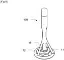
- the picture 3 represents a schematic view of a use of a heating utensil 10B according to a second embodiment.
- the heating utensil 10B comprises a foaming disc 15 connected to an electric motor 14 powered by the conversion device 12.
- the foaming disc 15 when a particular temperature is reached or according to a time control, can be rotated to mix or froth the food preparation which comprises for example milk.
- the remainder of the heating utensil 10B (in particular the heating portion 11 and the conversion device 12 for supplying an electrical receiver) and of the heating system being similar to the first embodiment, this will not be described again.
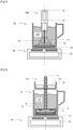
- the figure 4 represents the start of heating, with the food preparation 100 in the heating chamber 18 still at the same temperature as in the container 20: the valves 19 are closed.
- the figure 5 represents a moment during heating, with the food preparation 100 in the heating chamber 18 at a temperature higher than the temperature of the food preparation 100 in the container 20: the hot food preparation 100 rises in the chimney 17 due to its low density, and the valves 19 are open to allow a flow or current of food preparation 100 to enter the heating chamber 18. Consequently, a convection current is installed in the chimney 17 and overflows into the basket 16, to let brew grind 101, coffee or tea for example.
- the remainder of the heating utensil 10C in particular the heating portion 11 and the conversion device 12 for supplying an electrical receiver
- the heating system being similar to the first embodiment, this will not be described again.
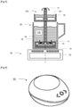
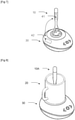
- the figure 6 shows an embodiment of the induction hob 30, with a housing, a laying surface and a man-machine interface (here buttons).
- the figure 7 represents the heating utensil 10 according to the first embodiment placed on the resting surface of the induction cooking plate 30 of the figure 6 , so as to show the possibilities of communication.
- the system is equipped with a communication module which comprises a first communication unit 41 embedded in the heating utensil 10 and a second communication unit 42 embedded in the induction cooking plate 30.
- the plate induction cooking 30 can perfectly receive information or preparation temperature instructions food, and adjust the heating power accordingly.
- the figure 8 represents the heating utensil 10A according to the first embodiment placed in a container 20 placed on the induction cooking plate 30 of the figure 6 .
- the container 20 is typically a cup made of ceramic or earthenware, or plastic. In any case, the container 20 is not made of ferromagnetic material.
- the figure 9 shows an embodiment of the heating utensil 10B according to the second embodiment, with the foaming disc 15 located above the heating portion 11.
Description
La présente invention concerne de manière générale un ustensile de chauffage agencé pour chauffer une préparation alimentaire placée dans un récipient. En particulier, l'invention concerne un ustensile de chauffage qui permet un chauffage à partir d'une plaque de cuisson à induction.The present invention generally relates to a heating utensil arranged to heat a food preparation placed in a container. In particular, the invention relates to a heating utensil which allows heating from an induction hob.
Il est connu dans l'art antérieur des ustensiles de chauffage agencés pour être utilisés avec une plaque de cuisson à induction, tel que celui divulgué dans le document
Un but de la présente invention est de répondre aux inconvénients de l'art antérieur mentionnés ci-dessus et en particulier, tout d'abord, de proposer un ustensile de chauffage qui permet de chauffer une préparation alimentaire dans tout type de récipient non ferromagnétique, tout en procurant une fonction supplémentaire à la fonction de chauffe pour l'utilisateur, et sans compliquer l'utilisation.An object of the present invention is to respond to the drawbacks of the prior art mentioned above and in particular, first of all, to propose a heating utensil which makes it possible to heat a food preparation in any type of non-ferromagnetic container, while providing an additional function to the heating function for the user, and without complicating use.
Pour cela un premier aspect de l'invention concerne un ustensile de chauffage, agencé pour être en contact avec une préparation alimentaire ou une boisson à chauffer et contenue dans un récipient non ferromagnétique, l'ustensile de chauffage comprenant :
- au moins une portion de chauffe, à plonger dans le récipient, en matériau ferromagnétique apte à être chauffé par une plaque de cuisson à induction de sorte à produire de la chaleur pour chauffer la préparation alimentaire, caractérisé en ce que l'ustensile comprend :
- un dispositif électrique comprenant un dispositif de conversion agencé pour convertir en courant électrique une partie des champs magnétiques générés par la plaque à induction et
- au moins un récepteur électrique apte à être alimenté par ce courant électrique.
- at least one heating portion, to be immersed in the container, made of ferromagnetic material capable of being heated by an induction hob so as to produce heat to heat the food preparation, characterized in that the utensil comprises:
- an electrical device comprising a conversion device arranged to convert part of the magnetic fields generated by the induction hob into electric current and
- at least one electrical receiver adapted to be powered by this electrical current.
L'ustensile de chauffage selon la mise en œuvre ci-dessus est à utiliser avec une plaque de cuisson à induction, et comprend :
- un récepteur électrique qui peut procurer une fonction supplémentaire ou complémentaire au chauffage et apporter ainsi une aide à l'utilisateur, et
- un dispositif de conversion qui génère du courant électrique en coopération avec la plaque de cuisson à induction et alimente le récepteur électrique, ce qui permet de procurer la fonction supplémentaire sans compliquer l'utilisation. En effet, avec le dispositif de conversion, l'ustensile de chauffage est complètement autonome pour fonctionner.
- an electrical receiver which can provide an additional or complementary function to the heating and thus provide assistance to the user, and
- a conversion device which generates electric current in cooperation with the induction hob and powers the electric receiver, which makes it possible to provide the additional function without complicating the use. Indeed, with the conversion device, the heating utensil is completely autonomous to operate.
Avantageusement, ledit au moins un récepteur électrique comprend au moins un capteur agencé pour mesurer une température de la préparation alimentaire. Un tel capteur de température permet de connaître la température réelle de la préparation culinaire.Advantageously, said at least one electrical receiver comprises at least one sensor arranged to measure a temperature of the food preparation. Such a temperature sensor makes it possible to know the actual temperature of the culinary preparation.
Avantageusement, ledit au moins un récepteur électrique comprend au moins un module de communication sans fil, agencé pour établir une connexion sans fil avec la plaque de cuisson à induction et/ou un appareil distant. Un tel dispositif de communication sans fil (par ondes radio, selon un protocole ou une norme WiFi ou Bluetooth® par exemple) permet de rendre l'ustensile de chauffage communicant de sorte à apporter des fonctions et/ou aides supplémentaires à l'utilisateur.Advantageously, said at least one electrical receiver comprises at least one wireless communication module, arranged to establish a wireless connection with the induction hob and/or a remote device. Such a wireless communication device (by radio waves, according to a WiFi or Bluetooth® protocol or standard, for example) makes it possible to make the heating utensil communicating so as to provide additional functions and/or aids to the user.
Avantageusement, le module de communication sans fil est agencé pour envoyer au moins une information de température de la préparation alimentaire ou une consigne de commande à un dispositif de pilotage de la plaque de cuisson à induction de manière à obtenir une régulation en température sur la base d'une température de consigne définie directement ou indirectement à partir d'une interface utilisateur disposée sur la plaque de cuisson à induction et/ou sur l'ustensile de chauffage et/ou sur un équipement tiers comme un terminal externe (un smartphone ou une tablette par exemple). Selon cette mise en œuvre, le dispositif de chauffage et son capteur de température font partie d'une chaine de régulation qui permet de piloter le chauffage en boucle fermée et prenant compte la température de la préparation alimentaire elle même. La température de consigne peut être définie directement ou indirectement, c'est-à-dire soit en valeur numérique (85°C... 100°C), soit par un intitulé de programmation (« Bouillir », « Thé », « Café », « Émulsion »). On peut également prévoir de piloter l'ustensile de chauffage et/ou la plaque de cuisson à induction depuis un téléphone portable.Advantageously, the wireless communication module is arranged to send at least one piece of food preparation temperature information or an order instruction to a device for controlling the induction hob so as to obtain temperature regulation on the basis a setpoint temperature defined directly or indirectly from a user interface placed on the induction hob and/or on the heating utensil and/or on third-party equipment such as an external terminal (a smartphone or a tablet for example). According to this implementation, the heating device and its temperature sensor are part of a regulation chain which makes it possible to control the heating in a closed loop and taking into account the temperature of the food preparation itself. The setpoint temperature can be defined directly or indirectly, i.e. either in numerical value (85°C... 100°C), or by a programming title (“Boiling”, “Tea”, “ Coffee”, “Emulsion”). We can also predict to control the heating utensil and/or the induction hob from a mobile phone.
Avantageusement, le récepteur électrique comprend au moins une unité de commande et au moins un actionneur. Un tel actionneur permet d'effectuer une opération (par exemple mécanique) sur la préparation alimentaire, ce qui procure une fonction de préparation supplémentaire autonome.Advantageously, the electrical receiver comprises at least one control unit and at least one actuator. Such an actuator makes it possible to perform an operation (for example mechanical) on the food preparation, which provides an independent additional preparation function.
Avantageusement, l'unité de commande est connectée au capteur de température, pour piloter ledit actionneur en fonction de la température de la préparation alimentaire.Advantageously, the control unit is connected to the temperature sensor, to control said actuator according to the temperature of the food preparation.
Avantageusement, ledit au moins un actionneur comprend un moteur électrique accouplé à un organe de préparation, tel qu'un dispositif ou disque mousseur ou un mélangeur. Un dispositif ou disque mousseur permet de faire mousser du lait par exemple. On peut aussi mélanger la préparation alimentaire, pour faire des sauces ou faire fondre du chocolat.Advantageously, said at least one actuator comprises an electric motor coupled to a preparation member, such as a foaming device or disc or a mixer. A foaming device or disc makes it possible to froth milk, for example. You can also mix the food preparation, to make sauces or melt chocolate.
Avantageusement, l'ustensile de chauffage comprend une pompe agencée pour générer un flux dans la préparation alimentaire ou boisson. Un tel flux peut être un remuage ou un mélange, ou encore un pompage pour transférer du liquide d'un premier endroit à un deuxième endroit.Advantageously, the heating utensil comprises a pump arranged to generate a flow in the food or drink preparation. Such flow may be stirring or mixing, or even pumping to transfer liquid from a first location to a second location.
Avantageusement, la pompe est une pompe thermique agencée pour convertir de l'énergie thermique en énergie mécanique et qui comprend :
- une chambre de chauffe dans laquelle est disposée l'au moins une portion de chauffe et comprenant au moins un clapet mobile entre une première position ouverte dans laquelle la préparation alimentaire ou boisson, disposée dans le récipient peut s'écouler de l'extérieur vers l'intérieur de la chambre de chauffe et une deuxième position fermée dans laquelle la boisson ne peut pas ou plus s'écouler de l'intérieur vers l'extérieur de la chambre de chauffe,
- au moins une cheminée pour acheminer la boisson selon un flux ascendant sous l'effet de la pression s'exerçant sur la boisson dans la chambre de chauffe,
- un panier dans lequel débouche la cheminée et agencé pour recevoir une mouture de café, de thé, ou de tisane à infuser par la boisson transitant par la cheminée pour se déverser dans le panier.
- a heating chamber in which the at least one heating portion is arranged and comprising at least one valve movable between a first open position in which the food preparation or drink, arranged in the container, can flow from the outside towards the inside the heating chamber and a second closed position in which the drink cannot or no longer flow from the inside to the outside of the heating chamber,
- at least one chimney for conveying the beverage in an upward flow under the effect of the pressure exerted on the beverage in the heating chamber,
- a basket into which the chimney opens and arranged to receive a grind of coffee, tea, or herbal tea to be infused by the drink passing through the chimney to flow into the basket.
La pompe thermique selon la mise en œuvre ci dessus fonctionne sur le principe de la convection et le mouvement du liquide est créé automatiquement par le chauffage. Le clapet peut être positionné pour s'ouvrir automatiquement lorsque le courant convectif s'installe, c'est-à-dire par différence de pression, ou peut être commandé électriquement, en étant alimenté par le dispositif de conversion.The heat pump according to the implementation above operates on the principle of convection and the movement of liquid is created automatically by heating. The valve can be positioned to open automatically when the convective current sets in, that is to say by pressure difference, or can be controlled electrically, being powered by the conversion device.
Avantageusement, le dispositif de conversion du dispositif électrique comprend au moins une bobine. Le dispositif de conversion est un dispositif à induction, agencé pour être excité ou induit par la plaque de cuisson à induction.Advantageously, the electrical device conversion device comprises at least one coil. The conversion device is an induction device, arranged to be excited or induced by the induction hob.
Avantageusement, le dispositif électrique comprend des moyens de stockage d'énergie électrique, tels qu'au moins une batterie. Une telle batterie permet de stocker le courant généré par le dispositif de conversion s'il n'y a pas de besoin en énergie, et le restituer lors de forte demande. Une telle batterie peut être une batterie chimique, ou un condensateur.Advantageously, the electrical device comprises electrical energy storage means, such as at least one battery. Such a battery makes it possible to store the current generated by the conversion device if there is no need for energy, and to restore it during high demand. Such a battery can be a chemical battery, or a capacitor.
Avantageusement, l'ustensile de chauffage comprend au moins une poignée.Advantageously, the heating utensil comprises at least one handle.
Avantageusement, le dispositif électrique comprend au moins une interface homme machine, telle qu'un écran d'affichage. Un tel écran, alimenté de manière autonome par le dispositif de conversion, améliore sensiblement l'ergonomie et le confort d'utilisation de l'ustensile de chauffage. Il peut être prévu d'afficher par exemple la température de la préparation alimentaire, ou des étapes/consignes de préparation.Advantageously, the electrical device comprises at least one man-machine interface, such as a display screen. Such a screen, powered autonomously by the conversion device, substantially improves the ergonomics and the comfort of use of the heating utensil. Provision may be made to display, for example, the temperature of the food preparation, or preparation steps/instructions.
Avantageusement, l'ustensile de chauffage comprend une unité de détection d'un courant induit, et des moyens d'information du niveau de courant induit. En particulier, on peut prévoir un circuit de détection de courant dans l'ustensile de chauffage qui compare avec un seuil attendu de courant. Si le courant mesuré est inférieur, alors un signal (par exemple une led rouge) indique que l'ustensile de chauffage n'est pas bien centré / positionné sur la plaque de cuisson à induction, si le courant dépasse le seuil, alors le signal (la LED devient verte) indique que l'ustensile de chauffage est bien centré et que le courant induit est satisfaisant.Advantageously, the heating utensil comprises a unit for detecting an induced current, and means for informing the level of induced current. In particular, a current detection circuit can be provided in the heating utensil which compares with an expected current threshold. If the measured current is lower, then a signal (for example a red led) indicates that the heating utensil is not well centered / positioned on the induction hob, if the current exceeds the threshold, then the signal (the LED turns green) indicates that the heating utensil is well centered and that the induced current is satisfactory.
Un deuxième aspect de l'invention concerne un système de chauffage, comprenant :
- un ustensile de chauffage selon le premier aspect de l'invention,
- un récipient en matériau non ferromagnétique,
- une plaque de cuisson à induction.
- a heating utensil according to the first aspect of the invention,
- a container made of non-ferromagnetic material,
- an induction hob.
Avantageusement, le système comprend un terminal externe, tel qu'un téléphone portable ou une tablette.Advantageously, the system includes an external terminal, such as a mobile phone or a tablet.
Il est entendu que toutes les caractéristiques techniques ci-dessus peuvent être combinées entre elles ou dissociées les unes des autres tant qu'il n'y a pas d'incohérence ou incompatibilité technique.It is understood that all the technical characteristics above can be combined with each other or separated from each other as long as there is no technical inconsistency or incompatibility.
D'autres caractéristiques et avantages de la présente invention apparaîtront plus clairement à la lecture de la description détaillée qui suit, décrivant des modes de réalisation de l'invention donnés à titre d'exemples nullement limitatifs et illustrés par les dessins annexés, dans lesquels :
- La
figure 1 représente un ustensile de chauffage selon un premier mode de réalisation. - La
figure 2 représente une vue schématique de l'utilisation de l'ustensile de chauffage de lafigure 1 . - La
figure 3 représente une vue schématique d'une utilisation d'un ustensile de chauffage selon un deuxième mode de réalisation. - La
figure 4 représente une vue schématique d'une utilisation d'un ustensile de chauffage selon un troisième mode de réalisation, en début de chauffage. - La
figure 5 représente l'utilisation de l'ustensile de chauffage de lafigure 4 , en cours de chauffage. - La
figure 6 représente une plaque de cuisson à induction pouvant être utilisée avec l'ustensile de chauffage selon la présente invention. - La
figure 7 représente l'ustensile de chauffage selon le premier mode de réalisation posé sur la plaque de cuisson à induction de lafigure 6 . - La
figure 8 représente l'ustensile de chauffage selon le premier mode de réalisation placé dans un récipient posé sur la plaque de cuisson à induction de lafigure 6 . - La
figure 9 représente l'ustensile de chauffage selon le deuxième mode de réalisation.
- The
figure 1 represents a heating utensil according to a first embodiment. - The
picture 2 represents a schematic view of the use of the heating utensil of thefigure 1 . - The
picture 3 represents a schematic view of a use of a heating utensil according to a second embodiment. - The
figure 4 represents a schematic view of a use of a heating utensil according to a third embodiment, at the start of heating. - The
figure 5 represents the use of the heating utensil of thefigure 4 , in the process of heating. - The
figure 6 shows an induction cooktop that can be used with the heating utensil according to the present invention. - The
figure 7 represents the heating utensil according to the first embodiment placed on the induction hob of thefigure 6 . - The
figure 8 represents the heating utensil according to the first embodiment placed in a container placed on the induction hob of thefigure 6 . - The
figure 9 represents the heating utensil according to the second embodiment.
La
Comme le montre la vue schématique de la
La préparation alimentaire 100 est typiquement un liquide plus ou moins épais et peut être, de manière non limitative, une boisson, une soupe, une bouillie, un liquide, de l'eau, du café, du thé, du lait, un mélange tel que du café sucré, du chocolat au lait...The
La portion de chauffe 11, en matériau ferromagnétique, est en regard de la plaque de cuisson à induction 30, si bien que des champs magnétiques générés par la plaque de cuisson 30 vont provoquer un échauffement de la portion de chauffe 11 (notamment par courants de Foucault), ce qui permet de chauffer la préparation alimentaire 100.The
Par ailleurs, comme évoqué ci-dessus, l'ustensile de chauffage 10A comprend un dispositif de conversion 12, qui est agencé pour convertir en courant électrique une partie des champs magnétiques générés par la plaque de cuisson par induction 30.Furthermore, as mentioned above, the
De plus, l'ustensile de chauffage comprend aussi un récepteur électrique 13 alimenté par le dispositif de conversion 12. Ainsi, l'ustensile de chauffage est complètement autonome.In addition, the heating utensil also includes an
Dans le détail, le dispositif de conversion électrique 12 peut comprendre une bobine, préférentiellement une bobine plate qui va fonctionner comme un induit pour générer du courant à partir des champs magnétiques de la plaque de cuisson 30. En ce qui concerne le récepteur électrique, on peut prévoir un capteur de température, et par exemple un afficheur, et/ou un dispositif de communication sans fil.In detail, the
Le capteur de température est prévu pour mesurer la température de la préparation alimentaire 100. A cet effet, il peut être agencé dans la partie immergée de la poignée 10m, ou dans le bras qui relient la poignée 10m à la portion de chauffe 11. L'afficheur peut quant à lui être disposé sur la partie supérieure de la poignée 10m, pour indiquer la température, à des fins d'information de l'utilisateur.The temperature sensor is provided for measuring the temperature of the
On peut aussi prévoir que le récepteur électrique comprend un dispositif de communication sans fil par ondes radio pour envoyer à un appareil électronique distant des informations relatives à la température. On peut par exemple envoyer à un téléphone portable les informations de température qui seront ensuite affichées pour l'utilisateur. On peut également envoyer ces informations de température à l'unité de commande 32 de la plaque de cuisson 30, pour commander/réguler le chauffage de manière précise en boucle fermée, en prenant en compte la température de la préparation alimentaire 100.Provision can also be made for the electrical receiver to comprise a device for wireless communication by radio waves to send information relating to the temperature to a remote electronic device. It is for example possible to send the temperature information to a mobile telephone which will then be displayed for the user. This temperature information can also be sent to the
La
La
- une chambre de chauffe 18 dans laquelle est disposée la portion de chauffe 11 et comprenant deux clapets 19 mobiles entre une première position ouverte (
figure 5 ) dans laquelle la préparation alimentaire 100 disposée dans le récipient 20 peut s'écouler de l'extérieur vers l'intérieur de la chambre de chauffe 18 et une deuxième position fermée (figure 4 ) dans laquelle la boisson ne peut plus s'écouler de l'intérieur vers l'extérieur de la chambre de chauffe 18, une cheminée 17 pour acheminer la préparation alimentaire 100 selon un flux ascendant sous l'effet de la pression s'exerçant sur la préparation alimentaire 100 dans la chambre de chauffe 18,un panier 16 dans lequel débouche la cheminée 17 et agencé pour recevoir une mouture 101 de café, de thé ou de tisane à infuser par la préparation alimentaire 100 transitant par la cheminée 17 pour se déverser dans le panier 16.
- a
heating chamber 18 in which theheating portion 11 is arranged and comprising twovalves 19 movable between a first open position (figure 5 ) in which thefood preparation 100 placed in thecontainer 20 can flow from the outside to the inside of theheating chamber 18 and a second closed position (figure 4 ) in which the drink cannot no longer flow from the inside to the outside of theheating chamber 18, - a
chimney 17 for conveying thefood preparation 100 according to an upward flow under the effect of the pressure exerted on thefood preparation 100 in theheating chamber 18, - a
basket 16 into which thechimney 17 opens and arranged to receive agrind 101 of coffee, tea or herbal tea to be infused by thefood preparation 100 passing through thechimney 17 to flow into thebasket 16.
Comme vu ci-dessus, la
La
La
On peut aussi prévoir une communication avec un troisième appareil, tel qu'un téléphone portable ou une tablette pour piloter le chauffage. Ces possibilités de communication sont valables pour tous les modes de réalisation.It is also possible to provide communication with a third device, such as a mobile phone or a tablet to control the heating. These communication possibilities are valid for all embodiments.
La
La
On comprendra que diverses modifications et/ou améliorations évidentes pour l'homme du métier peuvent être apportées aux différents modes de réalisation de l'invention décrits dans la présente description sans sortir du cadre de l'invention.It will be understood that various modifications and/or improvements obvious to those skilled in the art can be made to the various embodiments of the invention described in the present description without departing from the scope of the invention.
Claims (15)
- Heating utensil (10A; 10B; 10C), arranged to be in contact with a food preparation (100) or a beverage to be heated and contained in a non-ferromagnetic container (20), the heating utensil (10A; 10B; 10C) comprising:- at least one heating portion (11), to be immersed in the container (20), made of ferromagnetic material capable of being heated by an induction cooking plate (30) so as to produce heat to heat the food preparation (100),characterised in that the utensil comprises:- an electric device comprising a conversion device (12) arranged to convert into electric current some of the magnetic fields generated by the induction cooking plate (30), and- at least one electrical receiver (13, 14) capable of being powered by this electric current.
- Heating utensil (10A; 10B; 10C) according to claim 1, wherein the at least one electrical receiver (13, 14) comprises at least one sensor arranged to measure a temperature of the food preparation (100).
- Heating utensil (10A; 10B; 10C) according to one of claims 1 to 2, wherein the at least one electrical receiver (13, 14) comprises at least one wireless communication module, arranged to establish a wireless connection with the induction cooking plate (30) and/or a remote appliance.
- Heating utensil (10A; 10B; 10C) according to claim 3, dependent from claim 2, wherein the wireless communication module is arranged to send at least one item of temperature information of the food preparation (100) or a control setpoint to a device for controlling (32) the induction cooking plate (30) so as to obtain a temperature regulation based on a setpoint temperature defined directly or indirectly from a user interface disposed on the induction cooking plate (30) and/or on the heating utensil (10A; 10B; 10C) and/or on an item of third-party equipment, like an external terminal.
- Heating utensil (10A; 10B; 10C) according to one of claims 1 to 4, wherein the electrical receiver (13, 14) comprises at least one control unit and at least one actuator.
- Heating utensil (10A; 10B; 10C) according to claim 5, dependent from claim 2, wherein the control unit is connected to the temperature sensor, to control said actuator according to the temperature of the food preparation (100).
- Heating utensil (10A; 10B; 10C) according to one of claims 5 to 6, wherein said at least one actuator comprises an electric motor (14) coupled to a preparation member, such as a foaming device or disc (15) or a mixer.
- Heating utensil (10A; 10B; 10C) according to one of claims 1 to 7, comprising a pump arranged to generate a flow in the food preparation (100) or beverage.
- Heating utensil (10A; 10B; 10C) according to claim 8, wherein the pump is an electric pump.
- Heating utensil (10A; 10B; 10C) according to claim 8, wherein the pump is a heat pump arranged to convert the heat energy into mechanical energy and which comprises:- a heating chamber (18) wherein is disposed the at least one heating portion (11) and comprising at least one valve (19) which is movable between a first open position wherein a beverage disposed in the container (20) can flow from the outside to the inside of the heating chamber (18) and a second closed position, wherein the beverage can no longer flow from the inside to the outside of the heating chamber (18),- at least one funnel (17) to convey the beverage according to an ascending flow under the effect of the pressure being exerted on the beverage in the heating chamber (18),- a basket (16) wherein the funnel (17) opens out, and arranged to receive coffee, tea, or herbal tea grounds to be infused through the beverage passing through the funnel (17) to be poured into the basket (16).
- Heating utensil (10A; 10B; 10C) according to one of claims 1 to 10, wherein the conversion device (12) of the electric device comprises at least one coil.
- Heating utensil (10A; 10B; 10C) according to one of claims 1 to 11, wherein the electric device comprises electric energy storage means, such as at least one battery.
- Heating utensil (10A; 10B; 10C) according to one of claims 1 to 12, comprising at least one handle (10m).
- Heating utensil (10A; 10B; 10C) according to one of claims 1 to 13, wherein the electric device comprises at least one man-machine interface, such as a display screen.
- Heating system, comprising:- a heating utensil (10A; 10B; 10C) according to one of claims 1 to 13,- a container (20) made of non-ferromagnetic material,- an induction cooking plate (30).
Applications Claiming Priority (1)
| Application Number | Priority Date | Filing Date | Title |
|---|---|---|---|
| FR1909687A FR3100420B1 (en) | 2019-09-03 | 2019-09-03 | HEATING UTILITY |
Publications (2)
| Publication Number | Publication Date |
|---|---|
| EP3790359A1 EP3790359A1 (en) | 2021-03-10 |
| EP3790359B1 true EP3790359B1 (en) | 2022-02-16 |
Family
ID=68138581
Family Applications (1)
| Application Number | Title | Priority Date | Filing Date |
|---|---|---|---|
| EP20193936.0A Active EP3790359B1 (en) | 2019-09-03 | 2020-09-01 | Heating utensil |
Country Status (3)
| Country | Link |
|---|---|
| EP (1) | EP3790359B1 (en) |
| CN (1) | CN112438612A (en) |
| FR (1) | FR3100420B1 (en) |
Families Citing this family (1)
| Publication number | Priority date | Publication date | Assignee | Title |
|---|---|---|---|---|
| WO2023099673A1 (en) * | 2021-12-03 | 2023-06-08 | BSH Hausgeräte GmbH | Small domestic appliance |
Citations (11)
| Publication number | Priority date | Publication date | Assignee | Title |
|---|---|---|---|---|
| DE3721200A1 (en) | 1987-06-26 | 1989-01-05 | Wmf Wuerttemberg Metallwaren | Cooking vessel made of non-metallic material |
| JP2003272814A (en) | 2002-03-12 | 2003-09-26 | Manna:Kk | Supporting tool for serving electromagnetically heated food, and method and device for serving electromagnetically heated food |
| DE102006052475A1 (en) | 2006-11-07 | 2008-05-08 | Vincent Truffault | Kitchen stove for use in cooking system, has heatproof support provided with outer side/cooking side and magnet drive, where support is formed to allow transfer of heat energy from induction heating device in direction of cooking side |
| US20100000980A1 (en) | 2008-07-02 | 2010-01-07 | Bogdan Popescu | Induction Heating System with Versatile Inductive Cartridge |
| DE102008054904A1 (en) | 2008-12-18 | 2010-06-24 | BSH Bosch und Siemens Hausgeräte GmbH | Household appliance for inductive energy transfer |
| US20120000903A1 (en) | 2009-01-06 | 2012-01-05 | Access Business Group International Llc | Smart cookware |
| WO2014075923A1 (en) | 2012-11-14 | 2014-05-22 | Arcelik Anonim Sirketi | A food preparation appliance operated on an induction heating cooktop |
| US20140158698A1 (en) | 2011-07-13 | 2014-06-12 | Seb S.A. | Rechargeable Removable Handle |
| US20150327707A1 (en) | 2014-05-14 | 2015-11-19 | Hansol Technics Inc. | Heating container |
| DE102014111817A1 (en) | 2014-08-19 | 2016-02-25 | Nils Chudy | Heating system and method for inductive heating of liquids |
| WO2018189209A1 (en) | 2017-04-10 | 2018-10-18 | Drei Lilien Pvg Gmbh & Co. Kg | Method and devices for contactlessly and directly heating liquids and solids |
-
2019
- 2019-09-03 FR FR1909687A patent/FR3100420B1/en active Active
-
2020
- 2020-09-01 EP EP20193936.0A patent/EP3790359B1/en active Active
- 2020-09-02 CN CN202010907938.7A patent/CN112438612A/en active Pending
Patent Citations (11)
| Publication number | Priority date | Publication date | Assignee | Title |
|---|---|---|---|---|
| DE3721200A1 (en) | 1987-06-26 | 1989-01-05 | Wmf Wuerttemberg Metallwaren | Cooking vessel made of non-metallic material |
| JP2003272814A (en) | 2002-03-12 | 2003-09-26 | Manna:Kk | Supporting tool for serving electromagnetically heated food, and method and device for serving electromagnetically heated food |
| DE102006052475A1 (en) | 2006-11-07 | 2008-05-08 | Vincent Truffault | Kitchen stove for use in cooking system, has heatproof support provided with outer side/cooking side and magnet drive, where support is formed to allow transfer of heat energy from induction heating device in direction of cooking side |
| US20100000980A1 (en) | 2008-07-02 | 2010-01-07 | Bogdan Popescu | Induction Heating System with Versatile Inductive Cartridge |
| DE102008054904A1 (en) | 2008-12-18 | 2010-06-24 | BSH Bosch und Siemens Hausgeräte GmbH | Household appliance for inductive energy transfer |
| US20120000903A1 (en) | 2009-01-06 | 2012-01-05 | Access Business Group International Llc | Smart cookware |
| US20140158698A1 (en) | 2011-07-13 | 2014-06-12 | Seb S.A. | Rechargeable Removable Handle |
| WO2014075923A1 (en) | 2012-11-14 | 2014-05-22 | Arcelik Anonim Sirketi | A food preparation appliance operated on an induction heating cooktop |
| US20150327707A1 (en) | 2014-05-14 | 2015-11-19 | Hansol Technics Inc. | Heating container |
| DE102014111817A1 (en) | 2014-08-19 | 2016-02-25 | Nils Chudy | Heating system and method for inductive heating of liquids |
| WO2018189209A1 (en) | 2017-04-10 | 2018-10-18 | Drei Lilien Pvg Gmbh & Co. Kg | Method and devices for contactlessly and directly heating liquids and solids |
Non-Patent Citations (2)
| Title |
|---|
| ANONYMOUS: "MIITO - the sustainable alternative to the electric kettle", KICKSTARTER, 2 June 2015 (2015-06-02), pages 1 - 17, XP055974265, Retrieved from the Internet <URL:https://www.kickstarter.com/projects/747044530/miito- the-sustainable-alternative-to-the- electric/posts/1250635> |
| ANONYMOUS: "MIITO - the sustainable alternative to the electric kettle", KICKSTARTER, 8 June 2015 (2015-06-08), pages 1 - 15, XP055974270, Retrieved from the Internet <URL:https://www.kickstarter.com/projects/747044530/miito- the-sustainable-alternative-to-the- electric/posts/1250914> |
Also Published As
| Publication number | Publication date |
|---|---|
| FR3100420B1 (en) | 2021-07-23 |
| EP3790359A1 (en) | 2021-03-10 |
| CN112438612A (en) | 2021-03-05 |
| FR3100420A1 (en) | 2021-03-05 |
Similar Documents
| Publication | Publication Date | Title |
|---|---|---|
| US11786067B2 (en) | Machine for brewing tea | |
| US20180160847A1 (en) | Electric dispensing kettle system | |
| CN105326398B (en) | Liquid heating apparatus | |
| EP3273831B1 (en) | Cooking management device provided with a cooking vessel recognition system | |
| US9763537B2 (en) | Hot beverage maker | |
| EP3790359B1 (en) | Heating utensil | |
| US20150359380A1 (en) | Coffee maker and brewing method | |
| EP0610795B1 (en) | Electrical household appliance to prepare infusions comprising a controlling unit | |
| FR3037493A1 (en) | VAPOR COOKING ACCESSORIES FOR HEATING AND / OR STEAMING FOODS CONTAINED IN A CONTAINER | |
| CN104930563B (en) | A kind of intelligent temperature control electromagnetic oven | |
| EP2454919B1 (en) | Device for induction heating | |
| WO2012118455A2 (en) | Universal device for energy control in the form of a button | |
| KR101604429B1 (en) | Container heating apparatus | |
| KR102154934B1 (en) | Rotating cooking appliance | |
| FR2945608A1 (en) | Method for controlling cooking temperature of cooking utensil, involves controlling heating device based on heat command so that temperature at interior of cooking utensil converges towards setpoint temperature | |
| CN101856195A (en) | Multifunctional tea making appliance | |
| EP3273834B1 (en) | Device for managing cooking, furnished with an improved display | |
| CN209678212U (en) | A kind of intelligent hot kettle | |
| EP0623303B1 (en) | Electric cooking apparatus | |
| FR3098677A1 (en) | Cooking system including an induction cooking zone | |
| CN202234775U (en) | Electric kettle with filter screen | |
| EP0706341A1 (en) | Brewing apparatus | |
| CN214712047U (en) | Instant heating type automatic tea making and water boiling integrated machine | |
| EP2671477A1 (en) | Hot beverage preparation apparatus comprising leafless brew receptacle | |
| CN201641648U (en) | Multifunctional tea making appliance |
Legal Events
| Date | Code | Title | Description |
|---|---|---|---|
| PUAI | Public reference made under article 153(3) epc to a published international application that has entered the european phase |
Free format text: ORIGINAL CODE: 0009012 |
|
| STAA | Information on the status of an ep patent application or granted ep patent |
Free format text: STATUS: THE APPLICATION HAS BEEN PUBLISHED |
|
| AK | Designated contracting states |
Kind code of ref document: A1 Designated state(s): AL AT BE BG CH CY CZ DE DK EE ES FI FR GB GR HR HU IE IS IT LI LT LU LV MC MK MT NL NO PL PT RO RS SE SI SK SM TR |
|
| AX | Request for extension of the european patent |
Extension state: BA ME |
|
| STAA | Information on the status of an ep patent application or granted ep patent |
Free format text: STATUS: REQUEST FOR EXAMINATION WAS MADE |
|
| 17P | Request for examination filed |
Effective date: 20210708 |
|
| RBV | Designated contracting states (corrected) |
Designated state(s): AL AT BE BG CH CY CZ DE DK EE ES FI FR GB GR HR HU IE IS IT LI LT LU LV MC MK MT NL NO PL PT RO RS SE SI SK SM TR |
|
| GRAP | Despatch of communication of intention to grant a patent |
Free format text: ORIGINAL CODE: EPIDOSNIGR1 |
|
| STAA | Information on the status of an ep patent application or granted ep patent |
Free format text: STATUS: GRANT OF PATENT IS INTENDED |
|
| RIC1 | Information provided on ipc code assigned before grant |
Ipc: A47J 43/044 20060101ALI20211028BHEP Ipc: A47J 43/28 20060101ALI20211028BHEP Ipc: A47J 36/24 20060101ALI20211028BHEP Ipc: H05B 6/12 20060101AFI20211028BHEP |
|
| INTG | Intention to grant announced |
Effective date: 20211123 |
|
| GRAS | Grant fee paid |
Free format text: ORIGINAL CODE: EPIDOSNIGR3 |
|
| GRAA | (expected) grant |
Free format text: ORIGINAL CODE: 0009210 |
|
| STAA | Information on the status of an ep patent application or granted ep patent |
Free format text: STATUS: THE PATENT HAS BEEN GRANTED |
|
| AK | Designated contracting states |
Kind code of ref document: B1 Designated state(s): AL AT BE BG CH CY CZ DE DK EE ES FI FR GB GR HR HU IE IS IT LI LT LU LV MC MK MT NL NO PL PT RO RS SE SI SK SM TR |
|
| REG | Reference to a national code |
Ref country code: GB Ref legal event code: FG4D Free format text: NOT ENGLISH |
|
| REG | Reference to a national code |
Ref country code: CH Ref legal event code: EP |
|
| REG | Reference to a national code |
Ref country code: DE Ref legal event code: R096 Ref document number: 602020001888 Country of ref document: DE |
|
| REG | Reference to a national code |
Ref country code: AT Ref legal event code: REF Ref document number: 1469715 Country of ref document: AT Kind code of ref document: T Effective date: 20220315 |
|
| REG | Reference to a national code |
Ref country code: IE Ref legal event code: FG4D Free format text: LANGUAGE OF EP DOCUMENT: FRENCH |
|
| REG | Reference to a national code |
Ref country code: LT Ref legal event code: MG9D |
|
| REG | Reference to a national code |
Ref country code: NL Ref legal event code: MP Effective date: 20220216 |
|
| REG | Reference to a national code |
Ref country code: AT Ref legal event code: MK05 Ref document number: 1469715 Country of ref document: AT Kind code of ref document: T Effective date: 20220216 |
|
| PG25 | Lapsed in a contracting state [announced via postgrant information from national office to epo] |
Ref country code: SE Free format text: LAPSE BECAUSE OF FAILURE TO SUBMIT A TRANSLATION OF THE DESCRIPTION OR TO PAY THE FEE WITHIN THE PRESCRIBED TIME-LIMIT Effective date: 20220216 Ref country code: RS Free format text: LAPSE BECAUSE OF FAILURE TO SUBMIT A TRANSLATION OF THE DESCRIPTION OR TO PAY THE FEE WITHIN THE PRESCRIBED TIME-LIMIT Effective date: 20220216 Ref country code: PT Free format text: LAPSE BECAUSE OF FAILURE TO SUBMIT A TRANSLATION OF THE DESCRIPTION OR TO PAY THE FEE WITHIN THE PRESCRIBED TIME-LIMIT Effective date: 20220616 Ref country code: NO Free format text: LAPSE BECAUSE OF FAILURE TO SUBMIT A TRANSLATION OF THE DESCRIPTION OR TO PAY THE FEE WITHIN THE PRESCRIBED TIME-LIMIT Effective date: 20220516 Ref country code: NL Free format text: LAPSE BECAUSE OF FAILURE TO SUBMIT A TRANSLATION OF THE DESCRIPTION OR TO PAY THE FEE WITHIN THE PRESCRIBED TIME-LIMIT Effective date: 20220216 Ref country code: LT Free format text: LAPSE BECAUSE OF FAILURE TO SUBMIT A TRANSLATION OF THE DESCRIPTION OR TO PAY THE FEE WITHIN THE PRESCRIBED TIME-LIMIT Effective date: 20220216 Ref country code: HR Free format text: LAPSE BECAUSE OF FAILURE TO SUBMIT A TRANSLATION OF THE DESCRIPTION OR TO PAY THE FEE WITHIN THE PRESCRIBED TIME-LIMIT Effective date: 20220216 Ref country code: ES Free format text: LAPSE BECAUSE OF FAILURE TO SUBMIT A TRANSLATION OF THE DESCRIPTION OR TO PAY THE FEE WITHIN THE PRESCRIBED TIME-LIMIT Effective date: 20220216 Ref country code: BG Free format text: LAPSE BECAUSE OF FAILURE TO SUBMIT A TRANSLATION OF THE DESCRIPTION OR TO PAY THE FEE WITHIN THE PRESCRIBED TIME-LIMIT Effective date: 20220516 |
|
| PG25 | Lapsed in a contracting state [announced via postgrant information from national office to epo] |
Ref country code: PL Free format text: LAPSE BECAUSE OF FAILURE TO SUBMIT A TRANSLATION OF THE DESCRIPTION OR TO PAY THE FEE WITHIN THE PRESCRIBED TIME-LIMIT Effective date: 20220216 Ref country code: LV Free format text: LAPSE BECAUSE OF FAILURE TO SUBMIT A TRANSLATION OF THE DESCRIPTION OR TO PAY THE FEE WITHIN THE PRESCRIBED TIME-LIMIT Effective date: 20220216 Ref country code: GR Free format text: LAPSE BECAUSE OF FAILURE TO SUBMIT A TRANSLATION OF THE DESCRIPTION OR TO PAY THE FEE WITHIN THE PRESCRIBED TIME-LIMIT Effective date: 20220517 Ref country code: FI Free format text: LAPSE BECAUSE OF FAILURE TO SUBMIT A TRANSLATION OF THE DESCRIPTION OR TO PAY THE FEE WITHIN THE PRESCRIBED TIME-LIMIT Effective date: 20220216 Ref country code: AT Free format text: LAPSE BECAUSE OF FAILURE TO SUBMIT A TRANSLATION OF THE DESCRIPTION OR TO PAY THE FEE WITHIN THE PRESCRIBED TIME-LIMIT Effective date: 20220216 |
|
| PG25 | Lapsed in a contracting state [announced via postgrant information from national office to epo] |
Ref country code: IS Free format text: LAPSE BECAUSE OF FAILURE TO SUBMIT A TRANSLATION OF THE DESCRIPTION OR TO PAY THE FEE WITHIN THE PRESCRIBED TIME-LIMIT Effective date: 20220617 |
|
| REG | Reference to a national code |
Ref country code: DE Ref legal event code: R026 Ref document number: 602020001888 Country of ref document: DE |
|
| PLBI | Opposition filed |
Free format text: ORIGINAL CODE: 0009260 |
|
| PG25 | Lapsed in a contracting state [announced via postgrant information from national office to epo] |
Ref country code: SM Free format text: LAPSE BECAUSE OF FAILURE TO SUBMIT A TRANSLATION OF THE DESCRIPTION OR TO PAY THE FEE WITHIN THE PRESCRIBED TIME-LIMIT Effective date: 20220216 Ref country code: SK Free format text: LAPSE BECAUSE OF FAILURE TO SUBMIT A TRANSLATION OF THE DESCRIPTION OR TO PAY THE FEE WITHIN THE PRESCRIBED TIME-LIMIT Effective date: 20220216 Ref country code: RO Free format text: LAPSE BECAUSE OF FAILURE TO SUBMIT A TRANSLATION OF THE DESCRIPTION OR TO PAY THE FEE WITHIN THE PRESCRIBED TIME-LIMIT Effective date: 20220216 Ref country code: EE Free format text: LAPSE BECAUSE OF FAILURE TO SUBMIT A TRANSLATION OF THE DESCRIPTION OR TO PAY THE FEE WITHIN THE PRESCRIBED TIME-LIMIT Effective date: 20220216 Ref country code: DK Free format text: LAPSE BECAUSE OF FAILURE TO SUBMIT A TRANSLATION OF THE DESCRIPTION OR TO PAY THE FEE WITHIN THE PRESCRIBED TIME-LIMIT Effective date: 20220216 Ref country code: CZ Free format text: LAPSE BECAUSE OF FAILURE TO SUBMIT A TRANSLATION OF THE DESCRIPTION OR TO PAY THE FEE WITHIN THE PRESCRIBED TIME-LIMIT Effective date: 20220216 |
|
| 26 | Opposition filed |
Opponent name: GULDE & PARTNER PATENT- UND RECHTSANWALTSKANZLEI MBB Effective date: 20221005 |
|
| PLAB | Opposition data, opponent's data or that of the opponent's representative modified |
Free format text: ORIGINAL CODE: 0009299OPPO |
|
| PLAX | Notice of opposition and request to file observation + time limit sent |
Free format text: ORIGINAL CODE: EPIDOSNOBS2 |
|
| PG25 | Lapsed in a contracting state [announced via postgrant information from national office to epo] |
Ref country code: AL Free format text: LAPSE BECAUSE OF FAILURE TO SUBMIT A TRANSLATION OF THE DESCRIPTION OR TO PAY THE FEE WITHIN THE PRESCRIBED TIME-LIMIT Effective date: 20220216 |
|
| R26 | Opposition filed (corrected) |
Opponent name: GULDE & PARTNER PATENT- UND RECHTSANWALTSKANZLEI MBB Effective date: 20221005 |
|
| PG25 | Lapsed in a contracting state [announced via postgrant information from national office to epo] |
Ref country code: SI Free format text: LAPSE BECAUSE OF FAILURE TO SUBMIT A TRANSLATION OF THE DESCRIPTION OR TO PAY THE FEE WITHIN THE PRESCRIBED TIME-LIMIT Effective date: 20220216 |
|
| PLBB | Reply of patent proprietor to notice(s) of opposition received |
Free format text: ORIGINAL CODE: EPIDOSNOBS3 |
|
| PG25 | Lapsed in a contracting state [announced via postgrant information from national office to epo] |
Ref country code: MC Free format text: LAPSE BECAUSE OF FAILURE TO SUBMIT A TRANSLATION OF THE DESCRIPTION OR TO PAY THE FEE WITHIN THE PRESCRIBED TIME-LIMIT Effective date: 20220216 |
|
| REG | Reference to a national code |
Ref country code: BE Ref legal event code: MM Effective date: 20220930 |
|
| PG25 | Lapsed in a contracting state [announced via postgrant information from national office to epo] |
Ref country code: LU Free format text: LAPSE BECAUSE OF NON-PAYMENT OF DUE FEES Effective date: 20220901 |
|
| PG25 | Lapsed in a contracting state [announced via postgrant information from national office to epo] |
Ref country code: IT Free format text: LAPSE BECAUSE OF FAILURE TO SUBMIT A TRANSLATION OF THE DESCRIPTION OR TO PAY THE FEE WITHIN THE PRESCRIBED TIME-LIMIT Effective date: 20220216 Ref country code: IE Free format text: LAPSE BECAUSE OF NON-PAYMENT OF DUE FEES Effective date: 20220901 |
|
| PG25 | Lapsed in a contracting state [announced via postgrant information from national office to epo] |
Ref country code: BE Free format text: LAPSE BECAUSE OF NON-PAYMENT OF DUE FEES Effective date: 20220930 |
|
| PGFP | Annual fee paid to national office [announced via postgrant information from national office to epo] |
Ref country code: FR Payment date: 20230927 Year of fee payment: 4 Ref country code: DE Payment date: 20230911 Year of fee payment: 4 |