EP3790341A1 - Techniques d'attribution de ressources pour des communications de dispositif à dispositif (d2d) - Google Patents
Techniques d'attribution de ressources pour des communications de dispositif à dispositif (d2d) Download PDFInfo
- Publication number
- EP3790341A1 EP3790341A1 EP20203898.0A EP20203898A EP3790341A1 EP 3790341 A1 EP3790341 A1 EP 3790341A1 EP 20203898 A EP20203898 A EP 20203898A EP 3790341 A1 EP3790341 A1 EP 3790341A1
- Authority
- EP
- European Patent Office
- Prior art keywords
- dtp
- logic
- information
- bitmap
- subframe
- Prior art date
- Legal status (The legal status is an assumption and is not a legal conclusion. Google has not performed a legal analysis and makes no representation as to the accuracy of the status listed.)
- Pending
Links
- 238000000034 method Methods 0.000 title claims abstract description 67
- 238000004891 communication Methods 0.000 title abstract description 67
- 238000013468 resource allocation Methods 0.000 title abstract description 9
- 230000005540 biological transmission Effects 0.000 claims abstract description 145
- 230000015654 memory Effects 0.000 claims description 35
- 230000004044 response Effects 0.000 claims description 33
- 238000012545 processing Methods 0.000 description 23
- 230000006870 function Effects 0.000 description 14
- 238000005516 engineering process Methods 0.000 description 7
- 238000013461 design Methods 0.000 description 5
- 239000004065 semiconductor Substances 0.000 description 5
- 230000011664 signaling Effects 0.000 description 5
- 230000000694 effects Effects 0.000 description 4
- 230000005291 magnetic effect Effects 0.000 description 4
- 238000004519 manufacturing process Methods 0.000 description 4
- 230000003287 optical effect Effects 0.000 description 4
- 230000008569 process Effects 0.000 description 3
- 230000003068 static effect Effects 0.000 description 3
- 239000003990 capacitor Substances 0.000 description 2
- 238000004590 computer program Methods 0.000 description 2
- 229920000642 polymer Polymers 0.000 description 2
- 239000007787 solid Substances 0.000 description 2
- 230000000007 visual effect Effects 0.000 description 2
- 230000009471 action Effects 0.000 description 1
- 230000006978 adaptation Effects 0.000 description 1
- 230000003044 adaptive effect Effects 0.000 description 1
- 238000003491 array Methods 0.000 description 1
- 238000013475 authorization Methods 0.000 description 1
- 230000001413 cellular effect Effects 0.000 description 1
- 230000008859 change Effects 0.000 description 1
- 230000000295 complement effect Effects 0.000 description 1
- 238000010276 construction Methods 0.000 description 1
- 230000008878 coupling Effects 0.000 description 1
- 238000010168 coupling process Methods 0.000 description 1
- 238000005859 coupling reaction Methods 0.000 description 1
- 239000013078 crystal Substances 0.000 description 1
- 238000001514 detection method Methods 0.000 description 1
- 238000010586 diagram Methods 0.000 description 1
- 230000001747 exhibiting effect Effects 0.000 description 1
- 239000004744 fabric Substances 0.000 description 1
- 239000000835 fiber Substances 0.000 description 1
- 230000007774 longterm Effects 0.000 description 1
- 238000007726 management method Methods 0.000 description 1
- 238000013507 mapping Methods 0.000 description 1
- 239000000463 material Substances 0.000 description 1
- 230000007246 mechanism Effects 0.000 description 1
- 239000002184 metal Substances 0.000 description 1
- 239000000203 mixture Substances 0.000 description 1
- 238000010295 mobile communication Methods 0.000 description 1
- 230000006855 networking Effects 0.000 description 1
- 230000002093 peripheral effect Effects 0.000 description 1
- 229910052710 silicon Inorganic materials 0.000 description 1
- 239000010703 silicon Substances 0.000 description 1
- 238000010897 surface acoustic wave method Methods 0.000 description 1
- 230000001360 synchronised effect Effects 0.000 description 1
Images


Classifications
-
- H—ELECTRICITY
- H04—ELECTRIC COMMUNICATION TECHNIQUE
- H04W—WIRELESS COMMUNICATION NETWORKS
- H04W72/00—Local resource management
- H04W72/20—Control channels or signalling for resource management
- H04W72/23—Control channels or signalling for resource management in the downlink direction of a wireless link, i.e. towards a terminal
-
- H—ELECTRICITY
- H04—ELECTRIC COMMUNICATION TECHNIQUE
- H04W—WIRELESS COMMUNICATION NETWORKS
- H04W72/00—Local resource management
- H04W72/04—Wireless resource allocation
-
- H—ELECTRICITY
- H04—ELECTRIC COMMUNICATION TECHNIQUE
- H04W—WIRELESS COMMUNICATION NETWORKS
- H04W72/00—Local resource management
- H04W72/04—Wireless resource allocation
- H04W72/044—Wireless resource allocation based on the type of the allocated resource
- H04W72/0446—Resources in time domain, e.g. slots or frames
Definitions
- Embodiments herein generally relate to communications between devices in broadband wireless communications networks.
- an evolved node B may be responsible for allocating wireless channel resources to accommodate device-to-device (D2D) data transmissions of any D2D-capable user equipment (D2D UEs) that wish to perform such transmissions.
- An eNB can notify a D2D UE of resources allocated for D2D data transmissions by sending a scheduling grant to the D2D UE. Requiring the eNB to send a separate scheduling grant for each D2D data transmission may impose excessive, undesirable signaling overhead.
- the transmitting D2D UE may autonomously select the wireless channel resources to be used to accommodate its D2D data transmission(s) to a recipient D2D UE. Regardless of whether an eNB allocates the resources for the transmitting D2D UE or the transmitting D2D UE autonomously selects those resources, the transmitting D2D UE needs to send control information to notify the recipient D2D UE of the wireless channel resources via which it will perform its D2D data transmission(s) to the recipient D2D UE.
- the transmitting D2D UE is required to send control information identifying the specific resources to be used for each respective D2D data transmission, this may also constitute a cause of excessive signaling overhead.
- eNBs and D2D UEs be configured to communicate D2D resource allocation information in a compact, non-message-specific format.
- Various embodiments may be generally directed to resource allocation techniques for D2D communications.
- user equipment may comprise one or more radio frequency (RF) transceivers, one or more RF antennas, and logic, at least a portion of which is in hardware, the logic to receive a D2D control information (D2DCI) message comprising D2D data transmission pattern (DTP) information, identify a set of D2D transmission resources based on the DTP information, and send one or more D2D data messages using the set of D2D transmission resources.
- D2DCI D2D control information
- DTP D2D data transmission pattern
- Various embodiments may comprise one or more elements.
- An element may comprise any structure arranged to perform certain operations.
- Each element may be implemented as hardware, software, or any combination thereof, as desired for a given set of design parameters or performance constraints.
- an embodiment may be described with a limited number of elements in a certain topology by way of example, the embodiment may include more or less elements in alternate topologies as desired for a given implementation.
- any reference to "one embodiment” or “an embodiment” means that a particular feature, structure, or characteristic described in connection with the embodiment is included in at least one embodiment.
- the appearances of the phrases “in one embodiment,” “in some embodiments,” and “in various embodiments” in various places in the specification are not necessarily all referring to the same embodiment.
- the techniques disclosed herein may involve transmission of data over one or more wireless connections using one or more wireless mobile broadband technologies.
- various embodiments may involve transmissions over one or more wireless connections according to one or more 3rd Generation Partnership Project (3GPP), 3GPP Long Term Evolution (LTE), and/or 3GPP LTE-Advanced (LTE-A) technologies and/or standards, including their predecessors, revisions, progeny, and/or variants.
- 3GPP 3rd Generation Partnership Project
- LTE 3GPP Long Term Evolution
- LTE-A 3GPP LTE-Advanced
- GSM Global System for Mobile Communications
- EDGE Enhanced Data Rates for GSM Evolution
- UMTS Universal Mobile Telecommunications System
- HSPA High Speed Packet Access
- GSM/GPRS GSM with General Packet Radio Service
- wireless mobile broadband technologies and/or standards may also include, without limitation, any of the Institute of Electrical and Electronics Engineers (IEEE) 802.16 wireless broadband standards such as IEEE 802.16m and/or 802.16p, International Mobile Telecommunications Advanced (IMT-ADV), Worldwide Interoperability for Microwave Access (WiMAX) and/or WiMAX II, Code Division Multiple Access (CDMA) 2000 (e.g., CDMA2000 1xRTT, CDMA2000 EV-DO, CDMA EV-DV, and so forth), High Performance Radio Metropolitan Area Network (HIPERMAN), Wireless Broadband (WiBro), High Speed Downlink Packet Access (HSDPA), High Speed Orthogonal Frequency-Division Multiplexing (OFDM) Packet Access (HSOPA), High-Speed Uplink Packet Access (HSUPA) technologies and/or standards, including their predecessors, revisions, progeny, and/or variants.
- IEEE 802.16 wireless broadband standards such as IEEE 802.16m and/or 802.16p, International Mobile
- Some embodiments may additionally or alternatively involve wireless communications according to other wireless communications technologies and/or standards.
- Examples of other wireless communications technologies and/or standards that may be used in various embodiments may include, without limitation, other IEEE wireless communication standards such as the IEEE 802.11, IEEE 802.11a, IEEE 802.11b, IEEE 802.11g, IEEE 802.1 In, IEEE 802.11u, IEEE 802.11ac, IEEE 802.11ad, IEEE 802.11af, and/or IEEE 802.11ah standards, High-Efficiency Wi-Fi standards developed by the IEEE 802.11 High Efficiency WLAN (HEW) Study Group, Wi-Fi Alliance (WFA) wireless communication standards such as Wi-Fi, Wi-Fi Direct, Wi-Fi Direct Services, Wireless Gigabit (WiGig), WiGig Display Extension (WDE), WiGig Bus Extension (WBE), WiGig Serial Extension (WSE) standards and/or standards developed by the WFA Neighbor Awareness Networking (NAN) Task Group, machine-type communications (MTC) standards such as those embodied in 3GPP Technical Report (
- wired communications media may include a wire, cable, metal leads, printed circuit board (PCB), backplane, switch fabric, semiconductor material, twisted-pair wire, co-axial cable, fiber optics, and so forth.
- PCB printed circuit board
- switch fabric semiconductor material
- twisted-pair wire co-axial cable
- fiber optics and so forth.
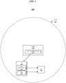
- FIG. 1 illustrates an example of an operating environment 100 in which the disclosed resource allocation techniques for D2D communications may be implemented in various embodiments.
- an eNB 102 serves a cell 104, and generally provides wireless connectivity to UEs 106 and 108.
- eNB 102 may perform operations such as managing radio resource control (RRC) states of UEs 106 and/or 108, allocating wireless channel resources for communications on the part of UEs 106 and/or 108, notifying UEs 106 and/or 108 of such allocated resources, and sending data to and/or receiving data from UEs 106 and/or 108.
- RRC radio resource control
- eNB 102 may implement frequency division duplexing (FDD), according to which it may allocate resources of one or more uplink (UL) channels to accommodate transmissions by UEs 106 and/or 108, and may allocate resources of one or more downlink (DL) channels to accommodate transmissions to UEs 106 and/or 108.
- FDD frequency division duplexing
- eNB 102 may implement time division duplexing (TDD).
- eNB 102 may be operative to select and report a TDD configuration to UEs 106 and 108, and the TDD configuration may specify subframes or other time intervals to be used for UL communications and subframes or other time intervals to be used for DL communications. In such embodiments, eNB 102 may then be operative to allocate resources of one or more UL subframes or other time intervals to accommodate transmissions by UE 106 and/or UE 108.
- the embodiments are not limited in this context.
- FIG. 2 illustrates an example of an operating environment 200 in which the disclosed resource allocation techniques for D2D communications may be implemented in various embodiments.
- UEs 106 and 108 of FIG. 1 are configured with D2D communication capabilities, and UE 106 has data for D2D transmission to UE 108.
- eNB 102 which is responsible for allocated wireless channel resources to accommodate D2D data transmissions, may send a D2D scheduling grant 210 to notify UE 106 of wireless channel resources that it may use for D2D data transmission.
- D2D scheduling grant 210 may comprise information within a control message that eNB 102 sends to UE 106, such as an RRC control message.
- UE 106 may use information in D2D scheduling grant 210 to identify wireless channel resources for use in D2D transmission of data to UE 108. Prior to performing its D2D data transmission(s) to UE 108, UE 106 may send control information 211 to notify UE 108 of the wireless channel resources allocated for its D2D data transmission(s). UE 106 may then perform D2D transmission of data 213 to UE 108, and UE 108 may receive the data 213 via some or all of the wireless channel resources allocated for D2D data transmission(s) of UE 106.
- UE 106 may have multiple D2D messages to transmit to UE 108, and/or may frequently generate D2D messages for transmission to UE 108.
- D2D scheduling grant 210 specifically identify distinct respective resource sets for each D2D message - or requiring that eNB 102 send separate D2D scheduling grants 210 for each D2D message that UE 106 has to send - may result in an excessive overall overhead associated with notifying UE 106 of the resources that it may use.
- D2D scheduling grant 210 identify resources that may be used to accommodate multiple D2D messages, but that it not be required to identify such resources in a D2D message-specific manner.
- D2D scheduling grant 210 be formatted such that it can convey such information while comprising a relatively compact structure.
- the format for the control information 211 that UE 106 sends to UE 108 may mirror that of the D2D scheduling grant 210 that eNB 102 sends to UE 106.
- the use of a compact, non-message-specific format for D2D scheduling grant 210 may also beneficially reduce overhead associated with transmissions of control information 211 by transmitting D2D UEs, even with respect to control information 211 sent by out-of-coverage transmitting D2D UEs.
- an eNB may be configured to select a D2D data transmission pattern (DTP) that generally specifies subframes or other time intervals during which a D2D UE is permitted to perform D2D transmissions.
- DTP D2D data transmission pattern
- the eNB may be configured to notify the D2D UE of the selected DTP by sending a D2D control information (D2DCI) message that comprises information identifying the selected DTP.
- D2DCI D2D control information
- the eNB may indicate the selected DTP simply by including a DTP index in the D2DCI message.
- the D2D UE may be operative to transmit multiple D2D messages using respective sets of available resources specified by the same DTP index. The embodiments are not limited in this context.
- FIG. 3 illustrates an example of an operating environment 300 in which the disclosed resource allocation techniques for D2D communications may be implemented in some embodiments.
- eNB 102 sends D2D control information 312 to UE 106.
- D2D control information 312 may be comprised within one or more information elements (IEs) of a control message, such as an RRC message.
- IEs information elements
- eNB 102 may periodically transmit D2D control information 312 to UE 106.
- D2D control information 312 may generally comprise parameters and/or other information to be applied by UE 106 in conjunction with D2D communications.
- eNB 102 may be operative to select a DTP for UE 106.
- the DTP may generally specify subframes or other time intervals during which UE 106 is permitted to perform D2D transmissions.
- eNB 102 may be operative to select the DTP for UE 106 from among a set of defined DTPs.
- FIG. 4 illustrates an example of a DTP set 400 such as may be representative of a DTP set from among which eNB 102 may select a DTP in various embodiments.
- DTP set 400 comprises DTPs 402, 404, 406, and 408.
- the subframes that are shaded in each DTP represent the subframes that are allocated for D2D transmissions according to that DTP.
- pattern duration shall be employed herein to denote the length of that DTP with respect to some time unit or unit that is a proxy for time.
- each of DTPs 402, 404, 406, and 408 comprises a pattern duration of forty subframes, or four frames.
- D2D allocation ratio shall be employed herein to denote the ratio between the amount of time units and/or wireless channel resources that the DTP allocates for D2D transmissions and the amount of time units and/or wireless channel resources that the DTP does not allocate for D2D transmissions over the course of the pattern duration.
- each of DTPs 402, 404, 406, and 408 allocates ten subframes for D2D transmissions and does not allocate the remaining thirty subframes for D2D transmissions.
- each of DTPs 402, 404, 406, and 408 exhibits a D2D allocation ratio of 1/3.
- DTPs 402, 404, 406, and 408 feature the same pattern durations and D2D allocation ratios, they are orthogonal in time with respect to their D2D allocations. During any particular subframe, only one of these four DTPs will indicate that D2D transmissions are permitted.
- an eNB that selects from among a DTP set may consider such orthogonality when selecting the DTP. For example, eNB 102 of FIG. 3 may select a DTP for UE 106 that is orthogonal in time to a DTP that it has selected for another UE.
- each DTP therein-DTP set 400 is representative of an FDD configuration, according to which UL transmissions may be performed in every subframe.
- the embodiments are not limited in this context, and the techniques herein may also be implemented in conjunction with FDD configurations.
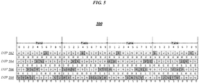
- FIG. 5 illustrates an example of a DTP set 500 such as may be representative of a DTP set from among which eNB 102 may select a DTP in various embodiments.
- DTP set 500 comprises DTPs 502, 504, 506, and 508.
- DTPs 502, 504, 506, and 508 each comprise pattern durations of forty subframes.
- each of DTPs 502, 504, 506, and 508 features a different D2D allocation ratio.
- DTP 502 features a D2D allocation ratio of 4/36 (or 1/9)
- DTP 504 features a D2D allocation ratio of 10/30 (or 1/3)
- DTP 506 features a D2D allocation ratio of 15/25 (or 3/5)
- DTP 508 features a D2D allocation ratio of 20/20 (or 1).
- Some of DTPs 502, 504, 506, and 508 are orthogonal in time to each other, while others are not.
- DTPs 502, 504, and 508 are mutually orthogonal in time, and DTP 502 is orthogonal in time to DTP 506, but DTP 506 is not orthogonal in time to either DTP 504 or DTP 508.
- an eNB that selects from among a DTP set such as DTP set 500 may consider a desired D2D data rate for a UE to which the selected DTP is to apply.
- the eNB may select a DTP exhibiting a D2D allocation ratio that is appropriate for the desired D2D data rate.
- the eNB may select a DTP featuring a relatively high D2D allocation ratio, such as DTP 508.
- the eNB may select a DTP featuring a relatively low D2D allocation ratio, such as DTP 502.
- D2D data rate considerations may be performed in concert with time orthogonality considerations.
- an eNB that has selected DTP 504 for a first D2D UE may also need select a DTP for a second D2D UE for which the desired D2D data rate can be achieved via DTP 506.
- the eNB may select DTP 508 for the second D2D UE, because DTP 508 is orthogonal in time to DTP 504 while DTP 506 is not.
- the embodiments are not limited to this example.
- a DTP set may comprise a lesser or greater number of different DTPs, which may or may not be of the same pattern duration or feature the same D2D allocation ratio, and may or may not be defined at a subframe level of granularity. It is again to be appreciated that the disclosed techniques may be implemented in conjunction with TDD configurations, despite the fact that the examples of FIGs. 4 and 5 are representative of FDD configurations. The embodiments are not limited in this context.
- eNB 102 may be operative to select the DTP for UE 106 based on a desired D2D data rate for UE 106. In various embodiments, eNB 102 may be operative to select a particular DTP for UE 106 based on a determination that the DTP is orthogonal in time to a DTP that it has selected for another D2D UE. In some embodiments, eNB 102 may be operative to report the selected DTP to UE 106 by sending D2D control information 312 comprising DTP information 314 that specifies the selected DTP.
- eNB 102 may select the DTP from among a defined DTP set, and a unique respective DTP index may be associated with each DTP in the set.
- each DTP index may comprise a sequence of bits.
- the DTP indices for DTPs 402, 404, 406, and 408 of FIG. 4 may be '00','01','10', and '11', respectively.
- eNB 102 may be operative to select a DTP for UE 106 and identify a DTP index 316 as the DTP index that corresponds to the selected DTP.
- eNB 102 may be operative to report the selected DTP to UE 106 by sending D2D control information 312 comprising DTP information 314 that contains the DTP index 316.
- eNB 102 may be operative to send D2D control information 312 to UE 106 over a physical downlink control channel (PDCCH).
- PDCCH physical downlink control channel
- UE 106 may be operative to receive D2D control information 312 and identify a set of D2D transmission resources based on DTP information 314. In various embodiments, UE 106 may identify the selected DTP based on DTP information 314 and identify the set of D2D transmission resources based on the selected DTP. In some embodiments, DTP information 314 may comprise DTP index 316, and UE 106 may be operative to identify the selected DTP based on DTP index 316. In various embodiments, UE 106 may determine a DTP bitmap 318 that corresponds to the DTP indicated by DTP information 314, and may identify the set of D2D transmission resources based on the DTP 318 bitmap.
- a corresponding DTP bitmap may a respective bit for each individual subframe or other time segment for which that DTP specifies whether D2D transmission is permitted.
- a DTP bitmap 318 that corresponds to DTP 402 of FIG. 4 may comprise forty bits - one for each of the forty subframes comprising the pattern duration of DTP 402.
- UE 106 may retrieve DTP bitmap 318 from among a plurality of DTP bitmaps contained in memory or storage. In some embodiments, from among the plurality of DTP bitmaps in memory or storage, UE 106 may retrieve a DTP bitmap 318 that it determines to be associated with DTP index 316. In various embodiments, UE 106 may be configured with the plurality of DTP bitmaps via RRC signaling from eNB 102. For example, in some embodiments, eNB 102 may configure UE 106 with the plurality of DTP bitmaps by sending an RRC message 320 that comprises DTP bitmap information 322.
- DTP bitmap information 322 may be comprised within an information element (IE) of a system information block (SIB) comprised in RRC message 320.
- DTP bitmap information 322 may comprise the plurality of DTP bitmaps and information specifying which respective one of a plurality of DTP indices corresponds to each of the plurality of DTP bitmaps.
- UE 106 may be configured with DTP bitmap information 322 at the time of initial device provisioning.
- eNB 102 may send DTP information 314 that comprises DTP bitmap 318 itself. The embodiments are not limited in this context.
- UE 106 may be operative to determine a DTP applicability interval for the DTP specified by DTP information 314.
- DTP applicability interval is defined to denote the time period during which the selection of that DTP remains in effect, such that it should be used to identify any resources needed for D2D transmissions.
- the DTP specified by DTP information 314 may remain in effect at UE 106 until a next D2D control information message is received.
- the DTP applicability interval for the DTP specified by DTP information 314 may comprise the time interval between receipt of D2D control information 312 and receipt of that next D2D control information message.
- UE 106 may be operative to use the DTP specified by DTP information 314 to identify D2D transmission resources comprised in the DTP applicability interval.
- the pattern duration of the DTP specified by DTP information 314 may differ from the DTP applicability interval of that DTP.
- the specified DTP may remain in effect for a period of time that is longer than the pattern duration of the specified DTP.
- UE 106 may apply the specified DTP repetitively over time in order to identify D2D transmission resources throughout the DTP applicability interval. For example, UE 106 may apply DTP 402 of FIG. 4 , which comprises a pattern length of forty subframes, to each of five forty-subframe subintervals within a DTP applicability interval comprising 200 subframes (twenty frames). The embodiments are not limited to this example.
- UE 106 may be operative to transmit one or more D2D data messages using D2D transmission resources comprised among those identified based on DTP information 314. For example, in various embodiments, UE 106 may be operative to transmit a D2D data message 324 to UE 108 using D2D transmission resources comprised among the identified resources. In some embodiments, UE 106 may be operative to send a D2D notification message 326 to UE 108 to report the D2D transmission resources to be used to send D2D data message 324. In some embodiments, UE 106 may be operative to send D2D notification message 326 to UE 108 over a direct control channel.
- D2D notification message 326 may comprise DTP information that is the same as - or similar to - the DTP information 314 received in D2D control information message 312. In some embodiments, D2D notification message may comprise the same DTP information 314 by design, in order to ensure that information regarding D2D transmission resources is communicated in an unambiguous form that is commonly interpreted by any D2D UE. In some embodiments, D2D notification message 326 may comprise a same DTP index 316 as was received in D2D control information message 312. In various embodiments, UE 108 may use the information comprised in D2D notification message 326 to identify the wireless channel resource via which to properly receive D2D data message 324. The embodiments are not limited in this context.
- D2D control information 312 may also comprise information describing a pattern or other configuration for D2D retransmissions.
- D2D control information 312 may identify a maximum number of retransmissions to be performed for D2D messages.
- D2D control information 312 may indicate that a maximum of three retransmissions may be performed for a given D2D transmission.
- D2D control information 312 may comprise information describing a relationship between D2D transmission resources and D2D retransmission resources.
- D2D control information 312 may comprise information usable to determine - given the subframe(s) during which a D2D message was transmitted - the subframe(s) during which a retransmission of that D2D message should be performed.
- the embodiments are not limited to this example.
- D2D subframe channels such as one or more of a D2D data channel, a D2D discovery channel, a D2D control channel, and/or another type of D2D channel could be defined in analogous fashion as the DTPs discussed above, using repeated bitmap patterns.
- DTP bitmaps could be adapted for use as D2D subframe bitmaps
- D2D subframe pattern indices could be defined for use, via RRC signaling, to identify D2D subframe configurations that are selected and/or applied.
- DTP indices and/or DTP bitmaps could be used to specify patterns within pre-allocated pools of resources for D2D operations.
- DTP bitmaps could be used to directly specify resources on a multiple frame basis in a fashion similar to a defined mechanism of channel state information (CSI) subframe pattern configuration. The embodiments are not limited in this context.
- FIG. 1 Some of the figures may include a logic flow. Although such figures presented herein may include a particular logic flow, it can be appreciated that the logic flow merely provides an example of how the general functionality as described herein can be implemented. Further, the given logic flow does not necessarily have to be executed in the order presented unless otherwise indicated. In addition, the given logic flow may be implemented by a hardware element, a software element executed by a processor, or any combination thereof. The embodiments are not limited in this context.
- FIG. 6 illustrates one embodiment of a logic flow 600 such as may be representative of operations that may be performed in some embodiments by UE 106.
- a D2D control information message may be received at 602 that comprises D2D transmission pattern information.
- UE 106 may be operative to receive D2D control information 312 from eNB 102 that comprises DTP information 314.
- a set of D2D transmission resources may be identified based on the D2D transmission pattern information.
- UE 106 may be operative to identify a set of D2D transmission resources based on a DTP index 316 comprised in DTP information 314.
- D2D control information may be sent to report the set of D2D transmission resources.
- UE 106 may be operative to send D2D notification message 326 to report the identified set of D2D transmission resources to UE 108.
- one or more D2D data messages may be sent using D2D transmission resources comprised among the identified set of D2D transmission resources.
- UE 106 may be operative to send one or more D2D data messages 324 to UE 108 using D2D transmission resources comprised among those it has identified based on DTP index 316.
- the embodiments are not limited to these examples.
- a D2D UE performing operations of logic flow 600 may operate in an autonomous mode according to which it selects the DTP itself. In such embodiments, rather than performing operations 602 and 604, the D2D UE may select the DTP and then proceed directly to 606, where it may send D2D control information comprising the a DTP index for the selected DTP.
- the embodiments are not limited in this context.
- FIG. 7 illustrates one embodiment of a logic flow 700 such as may be representative of operations that may be performed in various embodiments by eNB 102.
- a D2D transmission pattern may be selected at 702 from among a plurality of defined D2D transmission patterns.
- eNB 102 may be operative to select a D2D transmission pattern from among a plurality of defined D2D transmission patterns.
- a DTP index for the selected D2D transmission pattern may be identified.
- eNB 102 may be operative to identify a DTP index 316 for a D2D transmission pattern that it has selected.
- the selected D2D transmission pattern may be reported by sending D2D control information comprising the D2D index.
- eNB 102 may be operative to report a D2D transmission pattern that it has selected by sending DTP information 314 comprising the DTP index 316 for the selected D2D transmission pattern.
- the embodiments are not limited to these examples.
- FIG. 8A illustrates an embodiment of a storage medium 800.
- Storage medium 800 may comprise any non-transitory computer-readable storage medium or machine-readable storage medium, such as an optical, magnetic or semiconductor storage medium.
- storage medium 800 may comprise an article of manufacture.
- storage medium 800 may store computer-executable instructions, such as computer-executable instructions to implement logic flow 600 of FIG. 6 .
- Examples of a computer-readable storage medium or machine-readable storage medium may include any tangible media capable of storing electronic data, including volatile memory or non-volatile memory, removable or non-removable memory, erasable or non-erasable memory, writeable or re-writeable memory, and so forth.
- Examples of computer-executable instructions may include any suitable type of code, such as source code, compiled code, interpreted code, executable code, static code, dynamic code, object-oriented code, visual code, and the like. The embodiments are not limited in this context.
- FIG. 8B illustrates an embodiment of a storage medium 850.
- Storage medium 850 may comprise any non-transitory computer-readable storage medium or machine-readable storage medium, such as an optical, magnetic or semiconductor storage medium. In various embodiments, storage medium 850 may comprise an article of manufacture. In some embodiments, storage medium 850 may store computer-executable instructions, such as computer-executable instructions to implement logic flow 700 of FIG. 7 . Examples of a computer-readable/machine-readable storage medium and of computer-executable instructions may include - without limitation - any of the respective examples mentioned above in reference to storage medium 800 of FIG. 8A . The embodiments are not limited in this context.
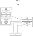
- FIG. 9 illustrates an embodiment of a communications device 900 that may implement one or more of eNB 102, UE 106, UE 108, logic flow 600 of FIG. 6 , logic flow 700 of FIG. 7 , storage medium 800 of FIG. 8A , and storage medium 850 of FIG. 8B .
- device 900 may comprise a logic circuit 928.
- the logic circuit 928 may include physical circuits to perform operations described for one or more of eNB 102, UE 106, UE 108, logic flow 600 of FIG. 6 , and logic flow 700 of FIG. 7 , for example.
- device 900 may include a radio interface 910, baseband circuitry 920, and computing platform 930, although the embodiments are not limited to this configuration.
- the device 900 may implement some or all of the structure and/or operations for one or more of eNB 102, UE 106, UE 108, logic flow 600 of FIG. 6 , logic flow 700 of FIG. 7 , storage medium 800 of FIG. 8A , storage medium 850 of FIG. 8B , and logic circuit 928 in a single computing entity, such as entirely within a single device.
- the device 900 may distribute portions of the structure and/or operations for one or more of eNB 102, UE 106, UE 108, logic flow 600 of FIG. 6 , logic flow 700 of FIG. 7 , storage medium 800 of FIG. 8A , storage medium 850 of FIG.
- a distributed system architecture such as a client-server architecture, a 3-tier architecture, an N-tier architecture, a tightly-coupled or clustered architecture, a peer-to-peer architecture, a master-slave architecture, a shared database architecture, and other types of distributed systems.
- a distributed system architecture such as a client-server architecture, a 3-tier architecture, an N-tier architecture, a tightly-coupled or clustered architecture, a peer-to-peer architecture, a master-slave architecture, a shared database architecture, and other types of distributed systems.
- a distributed system architecture such as a client-server architecture, a 3-tier architecture, an N-tier architecture, a tightly-coupled or clustered architecture, a peer-to-peer architecture, a master-slave architecture, a shared database architecture, and other types of distributed systems.
- the embodiments are not limited in this context.
- radio interface 910 may include a component or combination of components adapted for transmitting and/or receiving single-carrier or multi-carrier modulated signals (e.g., including complementary code keying (CCK), orthogonal frequency division multiplexing (OFDM), and/or single-carrier frequency division multiple access (SC-FDMA) symbols) although the embodiments are not limited to any specific over-the-air interface or modulation scheme.
- Radio interface 910 may include, for example, a receiver 912, a frequency synthesizer 914, and/or a transmitter 916.
- Radio interface 910 may include bias controls, a crystal oscillator and/or one or more antennas 918- f.
- radio interface 910 may use external voltage-controlled oscillators (VCOs), surface acoustic wave filters, intermediate frequency (IF) filters and/or RF filters, as desired. Due to the variety of potential RF interface designs an expansive description thereof is omitted.
- VCOs voltage-controlled oscillators
- IF intermediate frequency
- Baseband circuitry 920 may communicate with radio interface 910 to process receive and/or transmit signals and may include, for example, an analog-to-digital converter 922 for down converting received signals, a digital-to-analog converter 924 for up converting signals for transmission. Further, baseband circuitry 920 may include a baseband or physical layer (PHY) processing circuit 926 for PHY link layer processing of respective receive/transmit signals. Baseband circuitry 920 may include, for example, a medium access control (MAC) processing circuit 927 for MAC/data link layer processing. Baseband circuitry 920 may include a memory controller 932 for communicating with MAC processing circuit 927 and/or a computing platform 930, for example, via one or more interfaces 934.
- PHY physical layer
- PHY processing circuit 926 may include a frame construction and/or detection module, in combination with additional circuitry such as a buffer memory, to construct and/or deconstruct communication frames.
- MAC processing circuit 927 may share processing for certain of these functions or perform these processes independent of PHY processing circuit 926.
- MAC and PHY processing may be integrated into a single circuit.
- the computing platform 930 may provide computing functionality for the device 900. As shown, the computing platform 930 may include a processing component 940. In addition to, or alternatively of, the baseband circuitry 920, the device 900 may execute processing operations or logic for one or more of eNB 102, UE 106, UE 108, logic flow 600 of FIG. 6 , logic flow 700 of FIG. 7 , storage medium 800 of FIG. 8A , storage medium 850 of FIG. 8B , and logic circuit 928 using the processing component 940.
- the processing component 940 (and/or PHY 926 and/or MAC 927) may comprise various hardware elements, software elements, or a combination of both.
- Examples of hardware elements may include devices, logic devices, components, processors, microprocessors, circuits, processor circuits, circuit elements (e.g., transistors, resistors, capacitors, inductors, and so forth), integrated circuits, application specific integrated circuits (ASIC), programmable logic devices (PLD), digital signal processors (DSP), field programmable gate array (FPGA), memory units, logic gates, registers, semiconductor device, chips, microchips, chip sets, and so forth.
- ASIC application specific integrated circuits
- PLD programmable logic devices
- DSP digital signal processors
- FPGA field programmable gate array
- Examples of software elements may include software components, programs, applications, computer programs, application programs, system programs, software development programs, machine programs, operating system software, middleware, firmware, software modules, routines, subroutines, functions, methods, procedures, software interfaces, application program interfaces (API), instruction sets, computing code, computer code, code segments, computer code segments, words, values, symbols, or any combination thereof. Determining whether an embodiment is implemented using hardware elements and/or software elements may vary in accordance with any number of factors, such as desired computational rate, power levels, heat tolerances, processing cycle budget, input data rates, output data rates, memory resources, data bus speeds and other design or performance constraints, as desired for a given implementation.
- the computing platform 930 may further include other platform components 950.
- Other platform components 950 include common computing elements, such as one or more processors, multi-core processors, co-processors, memory units, chipsets, controllers, peripherals, interfaces, oscillators, timing devices, video cards, audio cards, multimedia input/output (I/O) components (e.g., digital displays), power supplies, and so forth.
- processors multi-core processors
- co-processors such as one or more processors, multi-core processors, co-processors, memory units, chipsets, controllers, peripherals, interfaces, oscillators, timing devices, video cards, audio cards, multimedia input/output (I/O) components (e.g., digital displays), power supplies, and so forth.
- I/O multimedia input/output
- Examples of memory units may include without limitation various types of computer readable and machine readable storage media in the form of one or more higher speed memory units, such as read-only memory (ROM), random-access memory (RAM), dynamic RAM (DRAM), Double-Data-Rate DRAM (DDRAM), synchronous DRAM (SDRAM), static RAM (SRAM), programmable ROM (PROM), erasable programmable ROM (EPROM), electrically erasable programmable ROM (EEPROM), flash memory, polymer memory such as ferroelectric polymer memory, ovonic memory, phase change or ferroelectric memory, silicon-oxide-nitride-oxide-silicon (SONOS) memory, magnetic or optical cards, an array of devices such as Redundant Array of Independent Disks (RAID) drives, solid state memory devices (e.g., USB memory, solid state drives (SSD) and any other type of storage media suitable for storing information.
- ROM read-only memory
- RAM random-access memory
- DRAM dynamic RAM
- DDRAM Double
- Device 900 may be, for example, an ultra-mobile device, a mobile device, a fixed device, a machine-to-machine (M2M) device, a personal digital assistant (PDA), a mobile computing device, a smart phone, a telephone, a digital telephone, a cellular telephone, user equipment, eBook readers, a handset, a one-way pager, a two-way pager, a messaging device, a computer, a personal computer (PC), a desktop computer, a laptop computer, a notebook computer, a netbook computer, a handheld computer, a tablet computer, a server, a server array or server farm, a web server, a network server, an Internet server, a work station, a mini-computer, a main frame computer, a supercomputer, a network appliance, a web appliance, a distributed computing system, multiprocessor systems, processor-based systems, consumer electronics, programmable consumer electronics, game devices, display, television, digital television, set top box, wireless access point, base station, node
- Embodiments of device 900 may be implemented using single input single output (SISO) architectures. However, certain implementations may include multiple antennas (e.g., antennas 918- f ) for transmission and/or reception using adaptive antenna techniques for beamforming or spatial division multiple access (SDMA) and/or using MIMO communication techniques.
- SISO single input single output
- certain implementations may include multiple antennas (e.g., antennas 918- f ) for transmission and/or reception using adaptive antenna techniques for beamforming or spatial division multiple access (SDMA) and/or using MIMO communication techniques.
- SDMA spatial division multiple access
- device 900 may be implemented using any combination of discrete circuitry, application specific integrated circuits (ASICs), logic gates and/or single chip architectures. Further, the features of device 900 may be implemented using microcontrollers, programmable logic arrays and/or microprocessors or any combination of the foregoing where suitably appropriate. It is noted that hardware, firmware and/or software elements may be collectively or individually referred to herein as “logic” or “circuit.”
- the exemplary device 900 shown in the block diagram of FIG. 9 may represent one functionally descriptive example of many potential implementations. Accordingly, division, omission or inclusion of block functions depicted in the accompanying figures does not infer that the hardware components, circuits, software and/or elements for implementing these functions would be necessarily be divided, omitted, or included in embodiments.
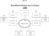
- FIG. 10 illustrates an embodiment of a broadband wireless access system 1000.
- broadband wireless access system 1000 may be an internet protocol (IP) type network comprising an internet 1010 type network or the like that is capable of supporting mobile wireless access and/or fixed wireless access to internet 1010.
- IP internet protocol
- broadband wireless access system 1000 may comprise any type of orthogonal frequency division multiple access (OFDMA)-based or single-carrier frequency division multiple access (SC-FDMA)-based wireless network, such as a system compliant with one or more of the 3GPP LTE Specifications and/or IEEE 802.16 Standards, and the scope of the claimed subject matter is not limited in these respects.
- OFDMA orthogonal frequency division multiple access
- SC-FDMA single-carrier frequency division multiple access
- radio access networks (RANs) 1012 and 1018 are capable of coupling with evolved node Bs (eNBs) 1014 and 1020, respectively, to provide wireless communication between one or more fixed devices 1016 and internet 1010 and/or between or one or more mobile devices 1022 and Internet 1010.
- RANs 1012 and 1018 may implement profiles that are capable of defining the mapping of network functions to one or more physical entities on broadband wireless access system 1000.
- eNBs 1014 and 1020 may comprise radio equipment to provide RF communication with fixed device 1016 and/or mobile device 1022, such as described with reference to device 900, and may comprise, for example, the PHY and MAC layer equipment in compliance with a 3GPP LTE Specification or an IEEE 802.16 Standard. eNBs 1014 and 1020 may further comprise an IP backplane to couple to Internet 1010 via RANs 1012 and 1018, respectively, although the scope of the claimed subject matter is not limited in these respects.
- Broadband wireless access system 1000 may further comprise a visited core network (CN) 1024 and/or a home CN 1026, each of which may be capable of providing one or more network functions including but not limited to proxy and/or relay type functions, for example authentication, authorization and accounting (AAA) functions, dynamic host configuration protocol (DHCP) functions, or domain name service controls or the like, domain gateways such as public switched telephone network (PSTN) gateways or voice over internet protocol (VoIP) gateways, and/or internet protocol (IP) type server functions, or the like.
- AAA authentication, authorization and accounting
- DHCP dynamic host configuration protocol
- IP internet protocol
- these are merely example of the types of functions that are capable of being provided by visited CN 1024 and/or home CN 1026, and the scope of the claimed subject matter is not limited in these respects.
- Visited CN 1024 may be referred to as a visited CN in the case where visited CN 1024 is not part of the regular service provider of fixed device 1016 or mobile device 1022, for example where fixed device 1016 or mobile device 1022 is roaming away from its respective home CN 1026, or where broadband wireless access system 1000 is part of the regular service provider of fixed device 1016 or mobile device 1022 but where broadband wireless access system 1000 may be in another location or state that is not the main or home location of fixed device 1016 or mobile device 1022.
- the embodiments are not limited in this context.
- Fixed device 1016 may be located anywhere within range of one or both of eNBs 1014 and 1020, such as in or near a home or business to provide home or business customer broadband access to Internet 1010 via eNBs 1014 and 1020 and RANs 1012 and 1018, respectively, and home CN 1026. It is worthy of note that although fixed device 1016 is generally disposed in a stationary location, it may be moved to different locations as needed. Mobile device 1022 may be utilized at one or more locations if mobile device 1022 is within range of one or both of eNBs 1014 and 1020, for example.
- operation support system (OSS) 1028 may be part of broadband wireless access system 1000 to provide management functions for broadband wireless access system 1000 and to provide interfaces between functional entities of broadband wireless access system 1000.
- Broadband wireless access system 1000 of FIG. 10 is merely one type of wireless network showing a certain number of the components of broadband wireless access system 1000, and the scope of the claimed subject matter is not limited in these respects.
- Various embodiments may be implemented using hardware elements, software elements, or a combination of both.
- hardware elements may include processors, microprocessors, circuits, circuit elements (e.g., transistors, resistors, capacitors, inductors, and so forth), integrated circuits, application specific integrated circuits (ASIC), programmable logic devices (PLD), digital signal processors (DSP), field programmable gate array (FPGA), logic gates, registers, semiconductor device, chips, microchips, chip sets, and so forth.
- Examples of software may include software components, programs, applications, computer programs, application programs, system programs, machine programs, operating system software, middleware, firmware, software modules, routines, subroutines, functions, methods, procedures, software interfaces, application program interfaces (API), instruction sets, computing code, computer code, code segments, computer code segments, words, values, symbols, or any combination thereof. Determining whether an embodiment is implemented using hardware elements and/or software elements may vary in accordance with any number of factors, such as desired computational rate, power levels, heat tolerances, processing cycle budget, input data rates, output data rates, memory resources, data bus speeds and other design or performance constraints.
- One or more aspects of at least one embodiment may be implemented by representative instructions stored on a machine-readable medium which represents various logic within the processor, which when read by a machine causes the machine to fabricate logic to perform the techniques described herein.
- Such representations known as "IP cores" may be stored on a tangible, machine readable medium and supplied to various customers or manufacturing facilities to load into the fabrication machines that actually make the logic or processor.
- Some embodiments may be implemented, for example, using a machine-readable medium or article which may store an instruction or a set of instructions that, if executed by a machine, may cause the machine to perform a method and/or operations in accordance with the embodiments.
- Such a machine may include, for example, any suitable processing platform, computing platform, computing device, processing device, computing system, processing system, computer, processor, or the like, and may be implemented using any suitable combination of hardware and/or software.
- the machine-readable medium or article may include, for example, any suitable type of memory unit, memory device, memory article, memory medium, storage device, storage article, storage medium and/or storage unit, for example, memory, removable or non-removable media, erasable or non-erasable media, writeable or re-writeable media, digital or analog media, hard disk, floppy disk, Compact Disk Read Only Memory (CD-ROM), Compact Disk Recordable (CD-R), Compact Disk Rewriteable (CD-RW), optical disk, magnetic media, magneto-optical media, removable memory cards or disks, various types of Digital Versatile Disk (DVD), a tape, a cassette, or the like.
- CD-ROM Compact Disk Read Only Memory
- CD-R Compact Disk Recordable
- CD-RW Compact Dis
- the instructions may include any suitable type of code, such as source code, compiled code, interpreted code, executable code, static code, dynamic code, encrypted code, and the like, implemented using any suitable high-level, low-level, object-oriented, visual, compiled and/or interpreted programming language.
- Coupled and “connected” along with their derivatives. These terms are not intended as synonyms for each other. For example, some embodiments may be described using the terms “connected” and/or “coupled” to indicate that two or more elements are in direct physical or electrical contact with each other. The term “coupled,” however, may also mean that two or more elements are not in direct contact with each other, but yet still co-operate or interact with each other.
- processing refers to the action and/or processes of a computer or computing system, or similar electronic computing device, that manipulates and/or transforms data represented as physical quantities (e.g., electronic) within the computing system's registers and/or memories into other data similarly represented as physical quantities within the computing system's memories, registers or other such information storage, transmission or display devices.
- physical quantities e.g., electronic
Applications Claiming Priority (4)
| Application Number | Priority Date | Filing Date | Title |
|---|---|---|---|
| US201461968286P | 2014-03-20 | 2014-03-20 | |
| US14/583,650 US9629145B2 (en) | 2014-03-20 | 2014-12-27 | Resource allocation techniques for device-to-device (D2D) communications |
| PCT/US2015/021169 WO2015142994A1 (fr) | 2014-03-20 | 2015-03-18 | Techniques d'allocation de ressources pour des communications de dispositif à dispositif (d2d) |
| EP15765384.1A EP3120643B1 (fr) | 2014-03-20 | 2015-03-18 | Techniques d'allocation de ressources pour des communications de dispositif à dispositif (d2d) |
Related Parent Applications (1)
| Application Number | Title | Priority Date | Filing Date |
|---|---|---|---|
| EP15765384.1A Division EP3120643B1 (fr) | 2014-03-20 | 2015-03-18 | Techniques d'allocation de ressources pour des communications de dispositif à dispositif (d2d) |
Publications (1)
| Publication Number | Publication Date |
|---|---|
| EP3790341A1 true EP3790341A1 (fr) | 2021-03-10 |
Family
ID=54143450
Family Applications (2)
| Application Number | Title | Priority Date | Filing Date |
|---|---|---|---|
| EP15765384.1A Active EP3120643B1 (fr) | 2014-03-20 | 2015-03-18 | Techniques d'allocation de ressources pour des communications de dispositif à dispositif (d2d) |
| EP20203898.0A Pending EP3790341A1 (fr) | 2014-03-20 | 2015-03-18 | Techniques d'attribution de ressources pour des communications de dispositif à dispositif (d2d) |
Family Applications Before (1)
| Application Number | Title | Priority Date | Filing Date |
|---|---|---|---|
| EP15765384.1A Active EP3120643B1 (fr) | 2014-03-20 | 2015-03-18 | Techniques d'allocation de ressources pour des communications de dispositif à dispositif (d2d) |
Country Status (12)
| Country | Link |
|---|---|
| US (2) | US9629145B2 (fr) |
| EP (2) | EP3120643B1 (fr) |
| JP (1) | JP6336609B2 (fr) |
| KR (1) | KR101926946B1 (fr) |
| AU (2) | AU2015231395A1 (fr) |
| CA (1) | CA2938309C (fr) |
| ES (1) | ES2832605T3 (fr) |
| MX (1) | MX362295B (fr) |
| MY (1) | MY175714A (fr) |
| RU (2) | RU2684750C2 (fr) |
| TW (2) | TWI657706B (fr) |
| WO (1) | WO2015142994A1 (fr) |
Families Citing this family (14)
| Publication number | Priority date | Publication date | Assignee | Title |
|---|---|---|---|---|
| WO2015152583A1 (fr) * | 2014-03-30 | 2015-10-08 | 엘지전자 주식회사 | Procédé pour émettre et recevoir un signal pour une communication de dispositif à dispositif dans un système de communication sans fil et dispositif associé |
| WO2015156605A1 (fr) * | 2014-04-08 | 2015-10-15 | 엘지전자 주식회사 | Procédé et appareil pour transmettre des données par un terminal de dispositif à dispositif dans un système de communication sans fil |
| US10484988B2 (en) | 2014-04-29 | 2019-11-19 | Lg Electronics Inc. | Method and device by which Device-to-Device user equipment transmits data in wireless communication system |
| EP3143821B1 (fr) | 2014-05-16 | 2020-01-01 | Sun Patent Trust | Procédé de communication de d2d et dispositif sans fil compatible d2d |
| CN105338633A (zh) * | 2014-07-08 | 2016-02-17 | 夏普株式会社 | 基站、用户设备及相关方法 |
| EP3198959B1 (fr) * | 2014-09-26 | 2020-11-25 | Telefonaktiebolaget LM Ericsson (publ) | Procédé et dispositif d'allocation de ressources pour la planification des attributions dans des communications de dispositif à dispositif |
| US10477527B2 (en) * | 2015-07-14 | 2019-11-12 | Qualcomm Incorporated | Semi-persistent scheduling mechanisms for vehicle-to-vehicle communication |
| US10644848B2 (en) | 2015-08-13 | 2020-05-05 | Electronics And Telecommunications Research Institute | Operation method of communication node supporting direct communication in network |
| EP3361766B1 (fr) * | 2015-11-06 | 2020-03-25 | Huawei Technologies Co., Ltd. | Procédé et dispositif permettant de déterminer une ressource radio et serveur de service |
| CN108370566B (zh) * | 2015-11-13 | 2023-04-11 | 索尼公司 | 通信方法、基站、基础设施节点以及通信终端 |
| WO2017156790A1 (fr) * | 2016-03-18 | 2017-09-21 | 广东欧珀移动通信有限公司 | Procédé et dispositif d2d utilisés pour des communications d2d |
| WO2018082053A1 (fr) * | 2016-11-04 | 2018-05-11 | 华为技术有限公司 | Procédé de configuration de ressource, dispositif terminal et station de base |
| EP3982681A1 (fr) * | 2017-03-24 | 2022-04-13 | Guangdong Oppo Mobile Telecommunications Corp., Ltd. | Procédé et appareil d'envoi d'informations, terminal, dispositif de réseau d'accès et système |
| US11212773B2 (en) * | 2018-06-27 | 2021-12-28 | Qualcomm Incorporated | Communication of sidelink transmission pattern to wireless wide area network (WWAN) |
Citations (2)
| Publication number | Priority date | Publication date | Assignee | Title |
|---|---|---|---|---|
| US20120113904A1 (en) * | 2010-11-08 | 2012-05-10 | Nicholas William Anderson | Releasing wireless resources |
| US20130142268A1 (en) * | 2010-08-12 | 2013-06-06 | Nokia Corporation | Configuring an uplink and downlink splitting pattern for device-to-device communication under a cellular network |
Family Cites Families (21)
| Publication number | Priority date | Publication date | Assignee | Title |
|---|---|---|---|---|
| KR20090072124A (ko) | 2007-12-28 | 2009-07-02 | 엘지전자 주식회사 | 사전 패턴 방식의 자원 구분 방법 및 적응적 자원 구분방법 |
| RU2459362C1 (ru) * | 2008-06-04 | 2012-08-20 | Нокиа Сименс Нетуоркс Ой | Сигнализация о качестве канала для процедур постоянного/полупостоянного выделения радиоресурсов |
| WO2010082084A1 (fr) * | 2009-01-16 | 2010-07-22 | Nokia Corporation | Appareil et procédé de planification de ressources pour communications de dispositif à dispositif |
| US8107883B2 (en) * | 2009-03-23 | 2012-01-31 | Nokia Corporation | Apparatus and method for interference avoidance in mixed device-to-device and cellular environment |
| WO2011147462A1 (fr) * | 2010-05-28 | 2011-12-01 | Nokia Siemens Networks Oy | Procédé et appareil permettant des communications de dispositif à dispositif |
| DE112011105271T5 (de) * | 2011-05-25 | 2014-03-06 | Renesas Mobile Corporation | Ressourcenzuordnung für eine D2D-Kommunikation |
| US10149334B2 (en) | 2011-11-14 | 2018-12-04 | Kyocera Corporation | Device-to-device communication management using macrocell communication resources |
| KR20130065002A (ko) * | 2011-12-09 | 2013-06-19 | 한국전자통신연구원 | 단말간 직접 통신 제어 방법 |
| CN110049573B (zh) * | 2012-01-17 | 2022-09-09 | 中兴通讯股份有限公司 | 一种无线通信方法和通信装置及通信系统 |
| US9763272B2 (en) * | 2012-02-27 | 2017-09-12 | Futurewei Technologies, Inc. | System and method for time resource allocation for device-to-device communication overlaid on a cellular network |
| US9143984B2 (en) | 2012-04-13 | 2015-09-22 | Intel Corporation | Mapping of enhanced physical downlink control channels in a wireless communication network |
| PL2665297T3 (pl) | 2012-05-15 | 2015-04-30 | Ericsson Telefon Ab L M | Alokacja lokalnej tożsamości urządzenia we wspomaganej przez sieć komunikacji typu "urządzenie z urządzeniem" D2D |
| GB2502603A (en) * | 2012-05-31 | 2013-12-04 | Renesas Mobile Corp | Wireless communications wherein modulation schemes for dominant interfering devices are selected to both use real symbols or complex symbols |
| CA2882856C (fr) * | 2012-08-23 | 2021-02-16 | Interdigital Patent Holdings, Inc. | Procede et appareil pour effectuer une decouverte de dispositif a dispositif |
| WO2014178671A1 (fr) * | 2013-05-01 | 2014-11-06 | Samsung Electronics Co., Ltd. | Procédés et appareil destinés à des systèmes de communication de dispositif à dispositif |
| US9392615B2 (en) * | 2013-08-20 | 2016-07-12 | Google Technology Holdings LLC | Methods and devices for allocating resources in device-to-device communication |
| TW201517673A (zh) * | 2013-09-26 | 2015-05-01 | Asustek Comp Inc | 裝置對裝置通訊資源分配方法以及使用此方法的基地台與用戶設備 |
| US9717094B2 (en) * | 2013-10-01 | 2017-07-25 | Samsung Electronics Co., Ltd. | Method and apparatus for device-to-device communication |
| US9603127B2 (en) * | 2013-11-08 | 2017-03-21 | Lg Electronics Inc. | Method and apparatus for allocating resources for performing device-to-device communication in wireless communication system |
| ES2728927T3 (es) * | 2014-01-29 | 2019-10-29 | Interdigital Patent Holdings Inc | Selección de recurso para descubrimiento o comunicación de dispositivo a dispositivo |
| US20150245334A1 (en) * | 2014-02-27 | 2015-08-27 | Innovative Sonic Corporation | Method and apparatus for device to device service in a wireless communication system |
-
2014
- 2014-12-27 US US14/583,650 patent/US9629145B2/en active Active
-
2015
- 2015-02-11 TW TW106137434A patent/TWI657706B/zh active
- 2015-02-11 TW TW104104567A patent/TWI610587B/zh active
- 2015-03-18 EP EP15765384.1A patent/EP3120643B1/fr active Active
- 2015-03-18 JP JP2016551723A patent/JP6336609B2/ja active Active
- 2015-03-18 EP EP20203898.0A patent/EP3790341A1/fr active Pending
- 2015-03-18 MY MYPI2016703022A patent/MY175714A/en unknown
- 2015-03-18 AU AU2015231395A patent/AU2015231395A1/en not_active Abandoned
- 2015-03-18 RU RU2017141177A patent/RU2684750C2/ru active
- 2015-03-18 KR KR1020167022519A patent/KR101926946B1/ko active IP Right Grant
- 2015-03-18 WO PCT/US2015/021169 patent/WO2015142994A1/fr active Application Filing
- 2015-03-18 CA CA2938309A patent/CA2938309C/fr active Active
- 2015-03-18 MX MX2016010798A patent/MX362295B/es active IP Right Grant
- 2015-03-18 RU RU2016134088A patent/RU2638942C1/ru active
- 2015-03-18 ES ES15765384T patent/ES2832605T3/es active Active
-
2017
- 2017-03-13 US US15/457,687 patent/US10200987B2/en active Active
-
2018
- 2018-04-27 AU AU2018202906A patent/AU2018202906B2/en active Active
Patent Citations (2)
| Publication number | Priority date | Publication date | Assignee | Title |
|---|---|---|---|---|
| US20130142268A1 (en) * | 2010-08-12 | 2013-06-06 | Nokia Corporation | Configuring an uplink and downlink splitting pattern for device-to-device communication under a cellular network |
| US20120113904A1 (en) * | 2010-11-08 | 2012-05-10 | Nicholas William Anderson | Releasing wireless resources |
Non-Patent Citations (1)
| Title |
|---|
| ERICSSON: "On scheduling procedure for D2D", vol. RAN WG1, no. Prague, Czech Republic; 20140210 - 20140214, 9 February 2014 (2014-02-09), XP050736279, Retrieved from the Internet <URL:http://www.3gpp.org/ftp/Meetings_3GPP_SYNC/RAN/RAN1/Docs/> [retrieved on 20140209] * |
Also Published As
| Publication number | Publication date |
|---|---|
| KR20160110983A (ko) | 2016-09-23 |
| TWI657706B (zh) | 2019-04-21 |
| RU2017141177A (ru) | 2019-02-13 |
| TW201542004A (zh) | 2015-11-01 |
| JP2017506044A (ja) | 2017-02-23 |
| TW201820916A (zh) | 2018-06-01 |
| WO2015142994A1 (fr) | 2015-09-24 |
| MX362295B (es) | 2019-01-10 |
| TWI610587B (zh) | 2018-01-01 |
| US10200987B2 (en) | 2019-02-05 |
| KR101926946B1 (ko) | 2018-12-07 |
| US20150271800A1 (en) | 2015-09-24 |
| AU2015231395A1 (en) | 2016-08-25 |
| CA2938309C (fr) | 2019-06-25 |
| MY175714A (en) | 2020-07-06 |
| RU2684750C2 (ru) | 2019-04-12 |
| RU2017141177A3 (fr) | 2019-02-13 |
| EP3120643A4 (fr) | 2017-11-08 |
| EP3120643B1 (fr) | 2020-10-28 |
| ES2832605T3 (es) | 2021-06-10 |
| US9629145B2 (en) | 2017-04-18 |
| AU2018202906B2 (en) | 2020-03-26 |
| US20180035410A1 (en) | 2018-02-01 |
| CA2938309A1 (fr) | 2015-09-24 |
| RU2638942C1 (ru) | 2017-12-19 |
| EP3120643A1 (fr) | 2017-01-25 |
| MX2016010798A (es) | 2016-11-29 |
| AU2018202906A1 (en) | 2018-05-17 |
| BR112016018808A2 (pt) | 2020-09-08 |
| JP6336609B2 (ja) | 2018-06-06 |
Similar Documents
| Publication | Publication Date | Title |
|---|---|---|
| AU2018202906B2 (en) | Resource allocation techniques for device-to-device (d2d) communications | |
| US10827301B2 (en) | Techniques for adjacent channel interference mitigation | |
| US10231182B2 (en) | Techniques for implicit indication of trigger frame start times | |
| US10075988B2 (en) | Discontinuous reception (DRX) alignment techniques for dual-connectivity architectures | |
| EP3202078B1 (fr) | Techniques d'attribution de sous-bande pour des dispositifs de communication de type machine (mtc) à largeur de bande réduite | |
| US10211960B2 (en) | Power offset signaling techniques for network-assisted interference cancellation and suppression (NAICS) receivers | |
| US10306452B2 (en) | Resource allocation techniques for device-to-device (D2D) discovery | |
| EP3140930B1 (fr) | Techniques de signalisation pour mesures de qualité de signal de référence reçu (rsrq) | |
| BR112016018808B1 (pt) | Aparelho, sistema, meio de armazenamento legível por computador e equipamento de usuário para alocação de recursos para comunicações de dispositivo-para-dispositivo |
Legal Events
| Date | Code | Title | Description |
|---|---|---|---|
| PUAI | Public reference made under article 153(3) epc to a published international application that has entered the european phase |
Free format text: ORIGINAL CODE: 0009012 |
|
| STAA | Information on the status of an ep patent application or granted ep patent |
Free format text: STATUS: THE APPLICATION HAS BEEN PUBLISHED |
|
| AC | Divisional application: reference to earlier application |
Ref document number: 3120643 Country of ref document: EP Kind code of ref document: P |
|
| AK | Designated contracting states |
Kind code of ref document: A1 Designated state(s): AL AT BE BG CH CY CZ DE DK EE ES FI FR GB GR HR HU IE IS IT LI LT LU LV MC MK MT NL NO PL PT RO RS SE SI SK SM TR |
|
| STAA | Information on the status of an ep patent application or granted ep patent |
Free format text: STATUS: REQUEST FOR EXAMINATION WAS MADE |
|
| 17P | Request for examination filed |
Effective date: 20210830 |
|
| RBV | Designated contracting states (corrected) |
Designated state(s): AL AT BE BG CH CY CZ DE DK EE ES FI FR GB GR HR HU IE IS IT LI LT LU LV MC MK MT NL NO PL PT RO RS SE SI SK SM TR |
|
| STAA | Information on the status of an ep patent application or granted ep patent |
Free format text: STATUS: EXAMINATION IS IN PROGRESS |
|
| 17Q | First examination report despatched |
Effective date: 20230330 |
|
| REG | Reference to a national code |
Ref country code: DE Ref legal event code: R079 Free format text: PREVIOUS MAIN CLASS: H04W0072040000 Ipc: H04W0072230000 |
|
| GRAP | Despatch of communication of intention to grant a patent |
Free format text: ORIGINAL CODE: EPIDOSNIGR1 |
|
| STAA | Information on the status of an ep patent application or granted ep patent |
Free format text: STATUS: GRANT OF PATENT IS INTENDED |
|
| RIC1 | Information provided on ipc code assigned before grant |
Ipc: H04W 72/0446 20230101ALN20231012BHEP Ipc: H04W 72/23 20230101AFI20231012BHEP |
|
| RIC1 | Information provided on ipc code assigned before grant |
Ipc: H04W 72/0446 20230101ALN20231016BHEP Ipc: H04W 72/23 20230101AFI20231016BHEP |
|
| INTG | Intention to grant announced |
Effective date: 20231114 |
|
| GRAJ | Information related to disapproval of communication of intention to grant by the applicant or resumption of examination proceedings by the epo deleted |
Free format text: ORIGINAL CODE: EPIDOSDIGR1 |
|
| STAA | Information on the status of an ep patent application or granted ep patent |
Free format text: STATUS: EXAMINATION IS IN PROGRESS |
|
| GRAP | Despatch of communication of intention to grant a patent |
Free format text: ORIGINAL CODE: EPIDOSNIGR1 |
|
| STAA | Information on the status of an ep patent application or granted ep patent |
Free format text: STATUS: GRANT OF PATENT IS INTENDED |
|
| INTC | Intention to grant announced (deleted) | ||
| RIC1 | Information provided on ipc code assigned before grant |
Ipc: H04W 72/0446 20230101ALN20240314BHEP Ipc: H04W 72/23 20230101AFI20240314BHEP |
|
| INTG | Intention to grant announced |
Effective date: 20240404 |