EP3789621A1 - Ensemble d'entretoise - Google Patents
Ensemble d'entretoise Download PDFInfo
- Publication number
- EP3789621A1 EP3789621A1 EP19195547.5A EP19195547A EP3789621A1 EP 3789621 A1 EP3789621 A1 EP 3789621A1 EP 19195547 A EP19195547 A EP 19195547A EP 3789621 A1 EP3789621 A1 EP 3789621A1
- Authority
- EP
- European Patent Office
- Prior art keywords
- spacer
- thread
- assembly according
- spacer assembly
- mount
- Prior art date
- Legal status (The legal status is an assumption and is not a legal conclusion. Google has not performed a legal analysis and makes no representation as to the accuracy of the status listed.)
- Granted
Links
- 125000006850 spacer group Chemical group 0.000 title claims abstract description 146
- 230000008878 coupling Effects 0.000 claims abstract description 6
- 238000010168 coupling process Methods 0.000 claims abstract description 6
- 238000005859 coupling reaction Methods 0.000 claims abstract description 6
- 239000002184 metal Substances 0.000 claims description 12
- 239000000463 material Substances 0.000 claims description 9
- 229920000642 polymer Polymers 0.000 claims description 4
- 150000001875 compounds Chemical class 0.000 claims description 2
- 230000008901 benefit Effects 0.000 description 5
- 238000004519 manufacturing process Methods 0.000 description 5
- 239000011248 coating agent Substances 0.000 description 2
- 238000000576 coating method Methods 0.000 description 2
- 238000012986 modification Methods 0.000 description 2
- 230000004048 modification Effects 0.000 description 2
- 230000004075 alteration Effects 0.000 description 1
- 238000006073 displacement reaction Methods 0.000 description 1
- 230000008676 import Effects 0.000 description 1
- 238000003780 insertion Methods 0.000 description 1
- 230000037431 insertion Effects 0.000 description 1
- 238000009434 installation Methods 0.000 description 1
- 238000000034 method Methods 0.000 description 1
- 230000002093 peripheral effect Effects 0.000 description 1
- 230000008569 process Effects 0.000 description 1
Images


Classifications
-
- F—MECHANICAL ENGINEERING; LIGHTING; HEATING; WEAPONS; BLASTING
- F16—ENGINEERING ELEMENTS AND UNITS; GENERAL MEASURES FOR PRODUCING AND MAINTAINING EFFECTIVE FUNCTIONING OF MACHINES OR INSTALLATIONS; THERMAL INSULATION IN GENERAL
- F16B—DEVICES FOR FASTENING OR SECURING CONSTRUCTIONAL ELEMENTS OR MACHINE PARTS TOGETHER, e.g. NAILS, BOLTS, CIRCLIPS, CLAMPS, CLIPS OR WEDGES; JOINTS OR JOINTING
- F16B5/00—Joining sheets or plates, e.g. panels, to one another or to strips or bars parallel to them
- F16B5/06—Joining sheets or plates, e.g. panels, to one another or to strips or bars parallel to them by means of clamps or clips
- F16B5/0607—Joining sheets or plates, e.g. panels, to one another or to strips or bars parallel to them by means of clamps or clips joining sheets or plates to each other
- F16B5/0621—Joining sheets or plates, e.g. panels, to one another or to strips or bars parallel to them by means of clamps or clips joining sheets or plates to each other in parallel relationship
- F16B5/0664—Joining sheets or plates, e.g. panels, to one another or to strips or bars parallel to them by means of clamps or clips joining sheets or plates to each other in parallel relationship at least one of the sheets or plates having integrally formed or integrally connected snap-in-features
-
- F—MECHANICAL ENGINEERING; LIGHTING; HEATING; WEAPONS; BLASTING
- F16—ENGINEERING ELEMENTS AND UNITS; GENERAL MEASURES FOR PRODUCING AND MAINTAINING EFFECTIVE FUNCTIONING OF MACHINES OR INSTALLATIONS; THERMAL INSULATION IN GENERAL
- F16B—DEVICES FOR FASTENING OR SECURING CONSTRUCTIONAL ELEMENTS OR MACHINE PARTS TOGETHER, e.g. NAILS, BOLTS, CIRCLIPS, CLAMPS, CLIPS OR WEDGES; JOINTS OR JOINTING
- F16B39/00—Locking of screws, bolts or nuts
- F16B39/22—Locking of screws, bolts or nuts in which the locking takes place during screwing down or tightening
- F16B39/24—Locking of screws, bolts or nuts in which the locking takes place during screwing down or tightening by means of washers, spring washers, or resilient plates that lock against the object
- F16B39/26—Locking of screws, bolts or nuts in which the locking takes place during screwing down or tightening by means of washers, spring washers, or resilient plates that lock against the object with spring washers fastened to the nut or bolt-head
-
- F—MECHANICAL ENGINEERING; LIGHTING; HEATING; WEAPONS; BLASTING
- F16—ENGINEERING ELEMENTS AND UNITS; GENERAL MEASURES FOR PRODUCING AND MAINTAINING EFFECTIVE FUNCTIONING OF MACHINES OR INSTALLATIONS; THERMAL INSULATION IN GENERAL
- F16B—DEVICES FOR FASTENING OR SECURING CONSTRUCTIONAL ELEMENTS OR MACHINE PARTS TOGETHER, e.g. NAILS, BOLTS, CIRCLIPS, CLAMPS, CLIPS OR WEDGES; JOINTS OR JOINTING
- F16B5/00—Joining sheets or plates, e.g. panels, to one another or to strips or bars parallel to them
- F16B5/06—Joining sheets or plates, e.g. panels, to one another or to strips or bars parallel to them by means of clamps or clips
- F16B5/0607—Joining sheets or plates, e.g. panels, to one another or to strips or bars parallel to them by means of clamps or clips joining sheets or plates to each other
- F16B5/0621—Joining sheets or plates, e.g. panels, to one another or to strips or bars parallel to them by means of clamps or clips joining sheets or plates to each other in parallel relationship
- F16B5/065—Joining sheets or plates, e.g. panels, to one another or to strips or bars parallel to them by means of clamps or clips joining sheets or plates to each other in parallel relationship the plates being one on top of the other and distanced from each other, e.g. by using protrusions to keep contact and distance
-
- B—PERFORMING OPERATIONS; TRANSPORTING
- B60—VEHICLES IN GENERAL
- B60Q—ARRANGEMENT OF SIGNALLING OR LIGHTING DEVICES, THE MOUNTING OR SUPPORTING THEREOF OR CIRCUITS THEREFOR, FOR VEHICLES IN GENERAL
- B60Q1/00—Arrangement of optical signalling or lighting devices, the mounting or supporting thereof or circuits therefor
- B60Q1/02—Arrangement of optical signalling or lighting devices, the mounting or supporting thereof or circuits therefor the devices being primarily intended to illuminate the way ahead or to illuminate other areas of way or environments
- B60Q1/04—Arrangement of optical signalling or lighting devices, the mounting or supporting thereof or circuits therefor the devices being primarily intended to illuminate the way ahead or to illuminate other areas of way or environments the devices being headlights
- B60Q1/0408—Arrangement of optical signalling or lighting devices, the mounting or supporting thereof or circuits therefor the devices being primarily intended to illuminate the way ahead or to illuminate other areas of way or environments the devices being headlights built into the vehicle body, e.g. details concerning the mounting of the headlamps on the vehicle body
- B60Q1/0433—Arrangement of optical signalling or lighting devices, the mounting or supporting thereof or circuits therefor the devices being primarily intended to illuminate the way ahead or to illuminate other areas of way or environments the devices being headlights built into the vehicle body, e.g. details concerning the mounting of the headlamps on the vehicle body the housing being fastened onto the vehicle body using screws
-
- B—PERFORMING OPERATIONS; TRANSPORTING
- B60—VEHICLES IN GENERAL
- B60Q—ARRANGEMENT OF SIGNALLING OR LIGHTING DEVICES, THE MOUNTING OR SUPPORTING THEREOF OR CIRCUITS THEREFOR, FOR VEHICLES IN GENERAL
- B60Q1/00—Arrangement of optical signalling or lighting devices, the mounting or supporting thereof or circuits therefor
- B60Q1/02—Arrangement of optical signalling or lighting devices, the mounting or supporting thereof or circuits therefor the devices being primarily intended to illuminate the way ahead or to illuminate other areas of way or environments
- B60Q1/04—Arrangement of optical signalling or lighting devices, the mounting or supporting thereof or circuits therefor the devices being primarily intended to illuminate the way ahead or to illuminate other areas of way or environments the devices being headlights
- B60Q1/0408—Arrangement of optical signalling or lighting devices, the mounting or supporting thereof or circuits therefor the devices being primarily intended to illuminate the way ahead or to illuminate other areas of way or environments the devices being headlights built into the vehicle body, e.g. details concerning the mounting of the headlamps on the vehicle body
- B60Q1/045—Arrangement of optical signalling or lighting devices, the mounting or supporting thereof or circuits therefor the devices being primarily intended to illuminate the way ahead or to illuminate other areas of way or environments the devices being headlights built into the vehicle body, e.g. details concerning the mounting of the headlamps on the vehicle body with provision for adjusting the alignment of the headlamp housing with respect to the vehicle body
-
- F—MECHANICAL ENGINEERING; LIGHTING; HEATING; WEAPONS; BLASTING
- F16—ENGINEERING ELEMENTS AND UNITS; GENERAL MEASURES FOR PRODUCING AND MAINTAINING EFFECTIVE FUNCTIONING OF MACHINES OR INSTALLATIONS; THERMAL INSULATION IN GENERAL
- F16B—DEVICES FOR FASTENING OR SECURING CONSTRUCTIONAL ELEMENTS OR MACHINE PARTS TOGETHER, e.g. NAILS, BOLTS, CIRCLIPS, CLAMPS, CLIPS OR WEDGES; JOINTS OR JOINTING
- F16B37/00—Nuts or like thread-engaging members
- F16B37/04—Devices for fastening nuts to surfaces, e.g. sheets, plates
- F16B37/044—Nut cages
-
- F—MECHANICAL ENGINEERING; LIGHTING; HEATING; WEAPONS; BLASTING
- F16—ENGINEERING ELEMENTS AND UNITS; GENERAL MEASURES FOR PRODUCING AND MAINTAINING EFFECTIVE FUNCTIONING OF MACHINES OR INSTALLATIONS; THERMAL INSULATION IN GENERAL
- F16B—DEVICES FOR FASTENING OR SECURING CONSTRUCTIONAL ELEMENTS OR MACHINE PARTS TOGETHER, e.g. NAILS, BOLTS, CIRCLIPS, CLAMPS, CLIPS OR WEDGES; JOINTS OR JOINTING
- F16B39/00—Locking of screws, bolts or nuts
- F16B39/22—Locking of screws, bolts or nuts in which the locking takes place during screwing down or tightening
- F16B39/28—Locking of screws, bolts or nuts in which the locking takes place during screwing down or tightening by special members on, or shape of, the nut or bolt
- F16B39/282—Locking by means of special shape of work-engaging surfaces, e.g. notched or toothed nuts
-
- F—MECHANICAL ENGINEERING; LIGHTING; HEATING; WEAPONS; BLASTING
- F16—ENGINEERING ELEMENTS AND UNITS; GENERAL MEASURES FOR PRODUCING AND MAINTAINING EFFECTIVE FUNCTIONING OF MACHINES OR INSTALLATIONS; THERMAL INSULATION IN GENERAL
- F16B—DEVICES FOR FASTENING OR SECURING CONSTRUCTIONAL ELEMENTS OR MACHINE PARTS TOGETHER, e.g. NAILS, BOLTS, CIRCLIPS, CLAMPS, CLIPS OR WEDGES; JOINTS OR JOINTING
- F16B41/00—Measures against loss of bolts, nuts, or pins; Measures against unauthorised operation of bolts, nuts or pins
- F16B41/002—Measures against loss of bolts, nuts or pins
-
- F—MECHANICAL ENGINEERING; LIGHTING; HEATING; WEAPONS; BLASTING
- F16—ENGINEERING ELEMENTS AND UNITS; GENERAL MEASURES FOR PRODUCING AND MAINTAINING EFFECTIVE FUNCTIONING OF MACHINES OR INSTALLATIONS; THERMAL INSULATION IN GENERAL
- F16B—DEVICES FOR FASTENING OR SECURING CONSTRUCTIONAL ELEMENTS OR MACHINE PARTS TOGETHER, e.g. NAILS, BOLTS, CIRCLIPS, CLAMPS, CLIPS OR WEDGES; JOINTS OR JOINTING
- F16B43/00—Washers or equivalent devices; Other devices for supporting bolt-heads or nuts
-
- F—MECHANICAL ENGINEERING; LIGHTING; HEATING; WEAPONS; BLASTING
- F16—ENGINEERING ELEMENTS AND UNITS; GENERAL MEASURES FOR PRODUCING AND MAINTAINING EFFECTIVE FUNCTIONING OF MACHINES OR INSTALLATIONS; THERMAL INSULATION IN GENERAL
- F16B—DEVICES FOR FASTENING OR SECURING CONSTRUCTIONAL ELEMENTS OR MACHINE PARTS TOGETHER, e.g. NAILS, BOLTS, CIRCLIPS, CLAMPS, CLIPS OR WEDGES; JOINTS OR JOINTING
- F16B5/00—Joining sheets or plates, e.g. panels, to one another or to strips or bars parallel to them
- F16B5/02—Joining sheets or plates, e.g. panels, to one another or to strips or bars parallel to them by means of fastening members using screw-thread
- F16B5/0216—Joining sheets or plates, e.g. panels, to one another or to strips or bars parallel to them by means of fastening members using screw-thread the position of the plates to be connected being adjustable
- F16B5/0233—Joining sheets or plates, e.g. panels, to one another or to strips or bars parallel to them by means of fastening members using screw-thread the position of the plates to be connected being adjustable allowing for adjustment perpendicular to the plane of the plates
-
- F—MECHANICAL ENGINEERING; LIGHTING; HEATING; WEAPONS; BLASTING
- F16—ENGINEERING ELEMENTS AND UNITS; GENERAL MEASURES FOR PRODUCING AND MAINTAINING EFFECTIVE FUNCTIONING OF MACHINES OR INSTALLATIONS; THERMAL INSULATION IN GENERAL
- F16B—DEVICES FOR FASTENING OR SECURING CONSTRUCTIONAL ELEMENTS OR MACHINE PARTS TOGETHER, e.g. NAILS, BOLTS, CIRCLIPS, CLAMPS, CLIPS OR WEDGES; JOINTS OR JOINTING
- F16B5/00—Joining sheets or plates, e.g. panels, to one another or to strips or bars parallel to them
- F16B5/06—Joining sheets or plates, e.g. panels, to one another or to strips or bars parallel to them by means of clamps or clips
- F16B5/0607—Joining sheets or plates, e.g. panels, to one another or to strips or bars parallel to them by means of clamps or clips joining sheets or plates to each other
- F16B5/0621—Joining sheets or plates, e.g. panels, to one another or to strips or bars parallel to them by means of clamps or clips joining sheets or plates to each other in parallel relationship
- F16B5/0657—Joining sheets or plates, e.g. panels, to one another or to strips or bars parallel to them by means of clamps or clips joining sheets or plates to each other in parallel relationship at least one of the plates providing a raised structure, e.g. of the doghouse type, for connection with the clamps or clips of the other plate
-
- F—MECHANICAL ENGINEERING; LIGHTING; HEATING; WEAPONS; BLASTING
- F16—ENGINEERING ELEMENTS AND UNITS; GENERAL MEASURES FOR PRODUCING AND MAINTAINING EFFECTIVE FUNCTIONING OF MACHINES OR INSTALLATIONS; THERMAL INSULATION IN GENERAL
- F16B—DEVICES FOR FASTENING OR SECURING CONSTRUCTIONAL ELEMENTS OR MACHINE PARTS TOGETHER, e.g. NAILS, BOLTS, CIRCLIPS, CLAMPS, CLIPS OR WEDGES; JOINTS OR JOINTING
- F16B5/00—Joining sheets or plates, e.g. panels, to one another or to strips or bars parallel to them
- F16B5/06—Joining sheets or plates, e.g. panels, to one another or to strips or bars parallel to them by means of clamps or clips
- F16B5/0607—Joining sheets or plates, e.g. panels, to one another or to strips or bars parallel to them by means of clamps or clips joining sheets or plates to each other
- F16B5/0621—Joining sheets or plates, e.g. panels, to one another or to strips or bars parallel to them by means of clamps or clips joining sheets or plates to each other in parallel relationship
- F16B2005/0671—Joining sheets or plates, e.g. panels, to one another or to strips or bars parallel to them by means of clamps or clips joining sheets or plates to each other in parallel relationship with unlocking by rotation
-
- F—MECHANICAL ENGINEERING; LIGHTING; HEATING; WEAPONS; BLASTING
- F16—ENGINEERING ELEMENTS AND UNITS; GENERAL MEASURES FOR PRODUCING AND MAINTAINING EFFECTIVE FUNCTIONING OF MACHINES OR INSTALLATIONS; THERMAL INSULATION IN GENERAL
- F16B—DEVICES FOR FASTENING OR SECURING CONSTRUCTIONAL ELEMENTS OR MACHINE PARTS TOGETHER, e.g. NAILS, BOLTS, CIRCLIPS, CLAMPS, CLIPS OR WEDGES; JOINTS OR JOINTING
- F16B21/00—Means for preventing relative axial movement of a pin, spigot, shaft or the like and a member surrounding it; Stud-and-socket releasable fastenings
- F16B21/06—Releasable fastening devices with snap-action
- F16B21/07—Releasable fastening devices with snap-action in which the socket has a resilient part
- F16B21/076—Releasable fastening devices with snap-action in which the socket has a resilient part the socket having a resilient part on its outside
-
- F—MECHANICAL ENGINEERING; LIGHTING; HEATING; WEAPONS; BLASTING
- F16—ENGINEERING ELEMENTS AND UNITS; GENERAL MEASURES FOR PRODUCING AND MAINTAINING EFFECTIVE FUNCTIONING OF MACHINES OR INSTALLATIONS; THERMAL INSULATION IN GENERAL
- F16B—DEVICES FOR FASTENING OR SECURING CONSTRUCTIONAL ELEMENTS OR MACHINE PARTS TOGETHER, e.g. NAILS, BOLTS, CIRCLIPS, CLAMPS, CLIPS OR WEDGES; JOINTS OR JOINTING
- F16B37/00—Nuts or like thread-engaging members
- F16B37/04—Devices for fastening nuts to surfaces, e.g. sheets, plates
- F16B37/041—Releasable devices
- F16B37/043—Releasable devices with snap action
Definitions
- the present invention relates to the general field of fasteners and mechanical connectors, and in particular, but not exclusively, to an improved spacer assembly for spacably coupling a first component and a second component.
- a vehicle or a at least a portion of a vehicle usually involves connecting, linking, coupling and mounting of many different components utilising many different types of fasteners, connecting elements, mounts, brackets and so on.
- spacer elements are needed to connect or couple two components that are spaced apart or are required to maintain a certain distance between the two components.
- a headlight may be fastened to a car body structure at a specific distance, though, the distance may vary due to manufacturing tolerances. Consequently, variable spacer devices or adjustable screw units are used to compensate for any tolerances.
- spacer devices are well known in the art and typically consist of at least two parts, one part forms a supporting part and is connected to the first component.
- the second part which forms a spacer part, is screwed into the support part by a left-hand thread forming an end surface that is spaced apart from the second component.
- some frictional element engages with the screw.
- the spacer part is carried along by the friction fit provided with the screw and threadingly moves out of the supporting part until it bridges the gap between the two spaced apart components.
- spacer devices or adjustable screw units have a relatively compact design with minimised axial displacement of the spacer part. Also, the handling and ease of use during pre-assembly of known spacer devices is made difficult due to its compact design. Further, known spacer devices are made from metal, making it relatively complex and rather expensive to manufacture, because different elements (e.g. the friction element) have to be added to the device to provide its functionality.
- spacer devices are usually transported or handled in a pre-assembled state, i.e. the spacer part is screwed into the support part.
- vibrations are likely to unscrew the spacer part from the support part eventually disassembling the components of the spacer device.
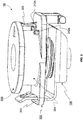
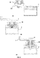
- Figure 1 shows a simplified schematic illustration of a spacer device 1 used to connect a first component 2 (e.g. a metal bracket) to a second component 4 (e.g. a plastic body or housing).
- a threaded connection bolt 20 is inserted through respective apertures 6, 8, 10 and threadingly engaged with a nut 12. The rotation of the connection bolt 20 activates the spacer device 1 until first and second component 2, 4 are fastened in a spaced relation to each other, as previously described.
- a spacer assembly for spacably coupling a first and second component with a threaded connection bolt, each one of the first and second component provided with one or more fitting apertures, comprising:
- said plurality of resilient friction elements may be provided inside a central recess at a first end of said cylindrical body.
- said plurality of resilient friction elements may be arranged radially relative to said central axis so as to form an extension of said axial through-hole.
- said plurality of resilient friction elements are an integral part of said cylindrical body.
- said plurality of resilient friction elements comprises any one of radially spaced apart elastic collar members and rib member arranged between said radially spaced apart collar members.
- the spacer assembly of the present invention provides the advantage of improved internal friction elements between the threadingly rotatable spacer member and the threaded connection bolt.
- the resilient friction elements are an integral part of the spacer member (i.e. an extension of the through hole) and are adapted to provide a calibrated friction force when engaging with the threaded connection bolt so as to axially move the spacer member out of the base member to bridge the space between the two components.
- the integral friction elements provide the advantage of minimised complexity reducing the manufacturing costs, as well as, improved performance.
- said spacer member may further comprise a flange member provided at a second end of said cylindrical body, opposite said first end, adapted to stoppingly engage with said through-hole mount during use.
- said flange member may comprise a resilient finger member projecting from an edge portion of said flange member in a direction parallel to said central axis towards said first end of said cylindrical body.
- said resilient finger member may be elastically deformable in at least a direction radial to said central axis.
- said base member may further comprise at least a first locking element, configured to interferingly engage with an end portion of said resilient finger member, and a second locking element, circumferentially spaced apart from said first locking element about said central axis and configured to stoppingly engage with said end portion of said resilient finger member, during use.
- each one of said first locking element and said second locking element may be provided on said upper surface of said planar base plate projecting normally away from said upper surface and radially outward from an outer surface of said cylindrical through-hole mount, said first locking element having a first radial length and said second locking element having a second radial length that is greater than said first radial length.
- said first locking element may comprise a cam surface, facing radially outward from said central axis, adapted to slidingly engage with said end portion of said resilient finger member so as to move said end portion of said resilient finger member radially outward and over said first locking element during rotation of said spacer element relative to said through-hole mount.
- said first locking element and said second locking element may project away from said upper surface to a predetermined distance from said upper surface.
- said predetermined distance may be substantially equal to the thread pitch of said mount thread.
- said resilient finger member may project to a length substantially equal to said mount length.
- the spacer assembly can be locked in its pre-assembled state allowing transport and handling of the spacer assembly without the risk of losing any one of the components due to disassembly caused by vibrations or other movements.
- the locking members of the base member and cooperating resilient finger member of the spacer member provide a stop that only engages when the spacer member is fully screwed into the base member preventing over rotation and potential damage of the engaging threads.
- the particular height of the locking elements i.e. ca. the length of the thread pitch
- ensures that the resilient finger of the spacer element will only lock with any one of the locking elements when the spacer member is fully screwed into the base member. In reverse, the resilient finger will disengage from the locking elements and move out of engagement through the first full rotation of the spacer member.
- said base member may further comprise a second clip portion at a second base plate end, opposite said first base plate end, projecting from said lower surface in a direction substantially normal to said lower surface, configured to be movably secured by a second one of the one or more fitting apertures of the first component.
- each one of said first and second clip portion may be configured to allow at least linear movement along an axis parallel to said centre axis.
- said predetermined friction force of said interference fit engagement between said mount thread and said spacer thread may be greater than the torque required to rotate said spacer member relative to said through-hole mount, during use.
- the length of said cylindrical body of said spacer member may be greater than said mount length.
- each one of said internal mount thread and corresponding said external spacer thread may be a left-hand thread, and said internal support thread may be a right-hand thread.
- said base member and said spacer member may be formed from a plastic material.
- said plastic material may comprise a polymer or a polymer compound material. This provides the advantage of considerably reducing manufacturing costs, as well as, the weight of the spacer assembly without compromising its functionality and performance.
- the use of plastic material for at least the spacer member provides a friction-fit engagement with the threaded connection bolt without damaging the bolt thread or its coating.
- said support member may be made from metal.
- the described example embodiment relates to an adjustable spacer assembly suitable for connecting two components.
- the embodiment(s) of the invention are normally applied in vehicles. Although the invention is described with respect to vehicles, the invention is not restricted to vehicles altogether, but may also be used in other structures requiring attachment of accessories or peripheral components to a structure.
- the terms 'connected', 'attached', 'coupled', 'mounted' are intended to include direct connections between two members without any other members interposed therebetween, as well as, indirect connections between members in which one or more other members are interposed therebetween.
- the terminology includes the words specifically mentioned above, derivatives thereof, and words of similar import.
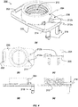
- FIG. 2 an example embodiment of a spacer assembly 10 is shown in its pre-assembled state, i.e. a metal support member 100 is clipped into the corresponding aperture 202 of a plastic base member 200 and a plastic spacer member 300 is fully screwed into the through-hole mount 204 of the base member 200 and locked into position via the engaging locking elements 212a, 212b and finger member 302.
- the spacer assembly 10 is transportable without the risk of disassembly (and loss of parts) from vibrations etc.
- the spacer member 300 is now described in detail referring to Figure 3 .
- the spacer member 300 comprises a cylindrical body 304 having a central through-hole 310 and an external left-hand thread 306 along its length.
- a flange 308 is provided at a top end of the cylindrical body 304 and a resilient finger member 302 is provided at the edge of the flange 308 projecting from a bottom surface 312 towards a bottom end 314 of the cylindrical body 304.
- the finger member 302 comprises an end portion 320 facing towards the cylindrical body 304 and having a rounded surface profile 322.
- a central recess 316 is provided at the bottom 314 housing three resilient friction elements 318 extending from the end of the through hole 310 into the recess 316.
- the three friction elements 318 are circumferentially arranged and spaced apart equidistant from each other.
- the inner diameter provided by the resilient friction elements 318 is smaller than the inner diameter of the through hole 310, so as to form an interference fit for a suitably sized threaded connection bolt 20, i.e. the inserted bolt 20 will push the three friction elements 318 apart to then exert a predetermined friction force onto the threaded connection bolt 20.
- any suitable number of circumferentially arranged and spaced apart friction elements 318 may be used.
- the friction elements 318 may be spaced apart at varying distances from each other.
- the base member 200 comprises a planar support plate 206 having a threaded through-hole mount 204 projecting from an upper surface 208.
- the through hole dimensions and left-hand internal thread 210 are configured to match the outer diameter and external thread 306 of the spacer 300 so that the spacer member 300 can threadingly engage with the though-hole mount 204 of the base member 200.
- An aperture 202 is provided at one end of the planar base plate 206 and is configured to retainingly receive a clip portion 102 of the support member 100.
- a first locking element 212a (retainer) is provided on the upper surface 208 extending radially outward from an outer surface of the through-hole mount 204.
- a second locking element 212b (stop) is provided on the upper surface 208 extending (approximately) radially outward from the outer surface of the through-hole mount 204 and circumferentially spaced apart from the first locking element 212a.
- Both, first and second locking elements 212a, 212b have a predetermined height from the upper surface 208, i.e. ca. the thread pitch 216 of the internal thread 210.
- the second locking element 212b is longer (in a radial direction from the through-hole mount 204) than the first locking element 212a.
- the first locking element 212a has a radially outward facing surface 214 with a rounded profile adapted to slidingly engage with the rounded end portion 320 of the finger member 302 during use.
- both, the rounded profile of the outward facing surface 214 of the first locking element 212a and the rounded end portion of the finger member 302 are adapted to slidingly engage during rotation of the spacer member 300 relative to the base member 200 such that the resilient finger member 302 is elastically bent radially outward and over the first locking member 212a to move to either side of the first locking member 212a depending on the direction of rotation.
- the radial length of the second locking member 212b is such that it provides a stop to the finger member 302 of the rotating spacer member 300, i.e. it is not possible to bend the resilient finger member 302 over the longer second locking element 212b.
- a clip 218 is provided at an end portion of the planar base plate 206 opposite the aperture 202.
- the clip 218 is projecting from a lower surface 220 into a direction opposite the through-hole mount 204.
- the clip 218 is configured to removably couple to one of the apertures provided in the housing of one of the two components that are connected.
- clip 218 comprises two resilient spaced apart clip members each having a stepped end portion adapted to lockingly engage with the aperture of the housing.
- any other suitable clip design may be used.
- the internal left-hand thread 210 is designed (thread thickness and pitch) so as to provide a high torque force when operably engaged with the external left-hand thread 306 of the spacer member 300.
- the support member 100 is typically made from metal (e.g. cut or stamped from sheet metal) comprises a planar support plate 104 having a central through-hole 106 with an internal thread 108 (e.g. a standard metric thread suitable to threadingly couple with a standard metric threaded bolt 20).
- the internal thread 108 is a right-hand thread, i.e. the internal thread 108 has to run in an opposite direction than the thread engagement between the spacer member 300 and the base member 200.
- the planar support plate 104 is shaped so as to provide a snug fit and axial alignment between the central through-hole106 and an aperture of the housing when slidingly inserted into the housing of the component.
- a clip portion 102 is extending from an end portion of the planar support plate 104 in a direction substantially perpendicular to the planar support plate 104, i.e. towards and through the aperture 202 of the base member 200 during assembly.
- An end portion 110 of the clip portion 102 is designed so as to allow the end portion 110 to freely move into the aperture 202 but prevent the end portion 110 from moving out of the aperture 202 without further intervention from a user.
- support member 100 When coupled to the base member 200, support member 100 is able to move relative to the base member 200 within the confines provided by the coupling between the clip 102 and the aperture 202 (e.g. limited liner movement relative to the base member 200, up and down, as well as, limited rotational movement of the support member 100 about the end portion 110 when engaged with the aperture 202).
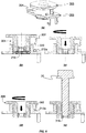
- Figure 6 shows a partly assembled spacer assembly 10 with the spacer member 300 fully locked with base member 200, i.e. the cylindrical body 304 is screwed into the through-hole mount 204 until the flange 308 abuts with the top end of the through-hole mount 204 and the resilient finger member 302 is locked between the first locking element 212a and the second locking element 212b.
- spacer member 300 is screwed into the threaded through-hole mount 204 by rotating spacer member 300 counter-clockwise (left-hand thread) until the rounded end portion 320 of the finger member 302 engages with the rounded outward facing surface 214 of the first locking member 212a.
- the rounded end portion 320 is elastically pushed out and over by the rounded outward facing surface 214 of the first locking member 212a.
- the rotation of spacer member 300 is eventually stopped by the second locking element 212b.
- flange 308 abuts the top end portion of the trough-hole mount 204 and finger member 320 is secured between the first and second locking element 212a, 212b.
- the second locking element 212b will prevent over-rotating the spacer member 300 and potentially damage threads 210 and 306.
- the spacer member 300 When unlocking the spacer member 300, the spacer member 300 is simple rotated clockwise so as to until the rounded end portion 320 of the finger member 302 engages with the rounded outward facing surface 214 of the first locking member212a. At this point, the rounded end portion 320 is elastically pushed out and over by the rounded outward facing surface 214 of the first locking member 212a. During further rotation of the spacer member 300, resilient finger member 302 is around the through-hole mount 204 and upwards following the pitch of the thread engagement 306, 210 such that finger member 302 is moved above and free of the locking elements 212a, 212b after one revolution.
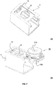
- Figure 6(e) shows threaded connection bolt 20 inserted into through-hole 310 of spacer member 300 and pushed towards engagement with the friction elements 318. It is understood that the friction fit between the connection bolt 20 and the friction elements 318 is stronger that the torque required to threadingly rotate the spacer member 300 relative to the through-hole mount 204 and axially move the spacer member 300 out of the through-hole mount 204.
- spacer assembly 10 may be used to fasten headlights to a car body structure (e.g. metal bracket 2), while automatically compensating for the gap between the two parts when screwing connection bolt 20 into the threaded through-hole 106 of the headlight housing 4.
- a car body structure e.g. metal bracket 2
- spacer assembly 10 is transported and delivered pre-assembled, i.e. spacer member 300, base member 200 and support member 100 are assembled in its locked state where the finger member 302 is lockingly engaged with the locking elements 2012a and 212b, preventing accidental unscrewing of the spacer member 300 (e.g. due to vibrations during transport) and potential loss of any component.
- the support member 100 of the pre-assembled spacer assembly 10 is inserted into the housing 4 such that the threaded through-hole 106 is axially aligned underneath a central aperture 8 of the housing 4.
- clip 218 is pushed into the aperture 14 of the housing 4, movably securing the base member 200 into position, i.e. coupled spacer member 300 and base member 200 are able to move linearly relative to the housing (limited up and down movement).
- connection bolt 20 e.g. M6 metal screw
- connection bolt 20 e.g. M6 metal screw
- connection bolt 20 is then rotated carrying along spacer member 300 via friction-fit engagement with the friction elements 318, thus axially moving the spacer member 300 out of the through-hole mount 204 and the connection bolt 20 into engagement with threaded through hole 106 until spacer member 300 has covered the distance and abuts against bracket 2.
- the torque required to rotate spacer member 300 relative to through-hole mount 204 exceeds the friction force provided by the friction elements 318 and connection bolt 20 moves axially into the threaded through hole 106 tightly fastening the housing 4 and bracket 2.
- the improved spacer assembly 10 comprises spacer member 300 and base member 200 made from a plastic material, and support member 100 made from a metal, therefore, providing a spacer assembly 10 that is considerably lighter than the conventional spacer devices made from metal (e.g. the improved spacer assembly is less than half the weight of an equivalent conventional spacer device), as well as, cheaper to manufacture.
- the spacer assembly 10 of the present invention provides an audible click when installing the spacer assembly 10 to housing 4.
- the friction elements 318 of the spacer member 300 are configured to engage with the connection bolt 20 without damaging the bolt coating.
- the increased length of the threaded cylindrical body 304 of the spacer member 300 allows covering a greater gap distance between the connecting components without compromising the thread engagement under load.
- through-hole thread 106 of the metal support member 100 is designed so as to provide an improved clamping force at the same torque force.
- components of the spacer assembly 10 made from different material and/or having different dimensions may entail force values that are different to the specific values described for the example embodiment.
Landscapes
- Engineering & Computer Science (AREA)
- General Engineering & Computer Science (AREA)
- Mechanical Engineering (AREA)
- Connection Of Plates (AREA)
Priority Applications (4)
| Application Number | Priority Date | Filing Date | Title |
|---|---|---|---|
| EP19195547.5A EP3789621B1 (fr) | 2019-09-05 | 2019-09-05 | Ensemble d'entretoise |
| US17/006,273 US11566649B2 (en) | 2019-09-05 | 2020-08-28 | Spacer assembly |
| BR102020018023-1A BR102020018023A2 (pt) | 2019-09-05 | 2020-09-03 | montagem de espaçador |
| CN202010915666.5A CN112443556A (zh) | 2019-09-05 | 2020-09-03 | 间隔件组件 |
Applications Claiming Priority (1)
| Application Number | Priority Date | Filing Date | Title |
|---|---|---|---|
| EP19195547.5A EP3789621B1 (fr) | 2019-09-05 | 2019-09-05 | Ensemble d'entretoise |
Publications (2)
| Publication Number | Publication Date |
|---|---|
| EP3789621A1 true EP3789621A1 (fr) | 2021-03-10 |
| EP3789621B1 EP3789621B1 (fr) | 2023-06-28 |
Family
ID=67874301
Family Applications (1)
| Application Number | Title | Priority Date | Filing Date |
|---|---|---|---|
| EP19195547.5A Active EP3789621B1 (fr) | 2019-09-05 | 2019-09-05 | Ensemble d'entretoise |
Country Status (4)
| Country | Link |
|---|---|
| US (1) | US11566649B2 (fr) |
| EP (1) | EP3789621B1 (fr) |
| CN (1) | CN112443556A (fr) |
| BR (1) | BR102020018023A2 (fr) |
Citations (6)
| Publication number | Priority date | Publication date | Assignee | Title |
|---|---|---|---|---|
| US5288191A (en) * | 1991-08-26 | 1994-02-22 | Ewald Witte Gmbh & Co. Kg | Device for the clamping attachment of spaced structural parts |
| EP1764516A2 (fr) * | 2005-09-15 | 2007-03-21 | GM Global Technology Operations, Inc. | Dispositif de montage vissé à compensation de tolérance |
| DE102006034463B3 (de) * | 2006-07-26 | 2008-01-10 | A. Raymond Et Cie | Vorrichtung zum Befestigen eines Anbauteiles und eines Trägerteiles in einem Abstand voneinander |
| DE102015103491A1 (de) * | 2015-02-02 | 2016-08-04 | Illinois Tool Works Inc. | Distanzmutter |
| DE102016212549A1 (de) * | 2016-07-11 | 2018-01-11 | Springfix Befestigungstechnik Gmbh | Vorrichtung zum Festlegen an einem Bauteil |
| DE102018201496A1 (de) * | 2018-01-31 | 2019-08-01 | Witte Automotive Gmbh | Toleranzausgleichsvorrichtung und Verfahren zur Herstellung einer Toleranzausgleichsvorrichtung |
Family Cites Families (18)
| Publication number | Priority date | Publication date | Assignee | Title |
|---|---|---|---|---|
| DE19839709C2 (de) * | 1998-09-01 | 2001-01-25 | Webasto Vehicle Sys Int Gmbh | Vorrichtung zum verspannenden Verbinden von zwei in Abstand befindlichen Bauteilen |
| DE19839710B4 (de) * | 1998-09-01 | 2005-04-28 | Webasto Ag Fahrzeugtechnik | Vorrichtung zum verspannenden Verbinden von zwei in Abstand befindlichen Bauteilen |
| US7488135B2 (en) * | 2003-07-29 | 2009-02-10 | Aoyama Seisakusho Co., Ltd. | Fastening device |
| DE10354062A1 (de) * | 2003-11-15 | 2005-06-16 | Witte-Velbert Gmbh & Co. Kg | Vorrichtung zum Verbinden zweier Bauteile in einer Abstandsstellung zueinander |
| DE202005009017U1 (de) * | 2005-06-08 | 2005-08-25 | Böllhoff Verbindungstechnik GmbH | Toleranzausgleichsanordnung aus Kunststoff |
| DE202005010873U1 (de) * | 2005-07-11 | 2005-09-22 | Böllhoff Verbindungstechnik GmbH | Toleranzausgleichseinrichtung aus Kunststoff |
| DE202005016823U1 (de) * | 2005-10-26 | 2006-02-09 | Böllhoff Verbindungstechnik GmbH | Befestigungseinrichtung mit Toleranzausgleich |
| US8002507B2 (en) * | 2008-05-15 | 2011-08-23 | The Boeing Company | Connector assembly for attaching a threaded fastener to a slotted surface |
| JP5035256B2 (ja) * | 2009-01-21 | 2012-09-26 | 株式会社豊田自動織機 | ねじ締結構造及びねじ締結方法 |
| US10145406B2 (en) * | 2009-11-05 | 2018-12-04 | Jpb Système | Self-locking screwing attachment devices and assemblies provided with same |
| US8920089B1 (en) * | 2011-06-20 | 2014-12-30 | Alpha Stamping Company | Device for securing a panel to a mounting stud |
| DE102012102906A1 (de) * | 2012-04-03 | 2013-10-10 | Böllhoff Verbindungstechnik GmbH | Befestigungsanordnung mit Toleranzausgleich sowie Verfahren zur Vormontage und Montage |
| DE102013202582B4 (de) * | 2013-02-18 | 2023-07-27 | Witte Automotive Gmbh | Toleranzausgleichsvorrichtung |
| US8978201B2 (en) * | 2013-08-08 | 2015-03-17 | Delphi Technologies, Inc. | Anti-rattle sleeve for a hinge joint |
| ES2575052B1 (es) * | 2014-12-23 | 2017-04-06 | Illinois Tools Works Inc. | Tuerca de compensación |
| DE102015120837A1 (de) * | 2015-12-01 | 2017-06-01 | Witte Automotive Gmbh | Vorrichtung zur Anbringung eines ersten Bauteils an einem zweiten Bauteil |
| DE102018108830A1 (de) * | 2017-04-13 | 2018-10-18 | Illinois Tool Works Inc. | System aus einem Anbauteil und einem Halteelement |
| CN114109999A (zh) * | 2020-08-31 | 2022-03-01 | 伊利诺斯工具制品有限公司 | 螺母紧固件组件 |
-
2019
- 2019-09-05 EP EP19195547.5A patent/EP3789621B1/fr active Active
-
2020
- 2020-08-28 US US17/006,273 patent/US11566649B2/en active Active
- 2020-09-03 CN CN202010915666.5A patent/CN112443556A/zh active Pending
- 2020-09-03 BR BR102020018023-1A patent/BR102020018023A2/pt not_active Application Discontinuation
Patent Citations (6)
| Publication number | Priority date | Publication date | Assignee | Title |
|---|---|---|---|---|
| US5288191A (en) * | 1991-08-26 | 1994-02-22 | Ewald Witte Gmbh & Co. Kg | Device for the clamping attachment of spaced structural parts |
| EP1764516A2 (fr) * | 2005-09-15 | 2007-03-21 | GM Global Technology Operations, Inc. | Dispositif de montage vissé à compensation de tolérance |
| DE102006034463B3 (de) * | 2006-07-26 | 2008-01-10 | A. Raymond Et Cie | Vorrichtung zum Befestigen eines Anbauteiles und eines Trägerteiles in einem Abstand voneinander |
| DE102015103491A1 (de) * | 2015-02-02 | 2016-08-04 | Illinois Tool Works Inc. | Distanzmutter |
| DE102016212549A1 (de) * | 2016-07-11 | 2018-01-11 | Springfix Befestigungstechnik Gmbh | Vorrichtung zum Festlegen an einem Bauteil |
| DE102018201496A1 (de) * | 2018-01-31 | 2019-08-01 | Witte Automotive Gmbh | Toleranzausgleichsvorrichtung und Verfahren zur Herstellung einer Toleranzausgleichsvorrichtung |
Also Published As
| Publication number | Publication date |
|---|---|
| CN112443556A (zh) | 2021-03-05 |
| US20210071696A1 (en) | 2021-03-11 |
| EP3789621B1 (fr) | 2023-06-28 |
| BR102020018023A2 (pt) | 2021-05-25 |
| US11566649B2 (en) | 2023-01-31 |
Similar Documents
| Publication | Publication Date | Title |
|---|---|---|
| US20070092355A1 (en) | Fastening apparatus with tolerance compensation | |
| US6357953B1 (en) | Tolerance compensation apparatus | |
| US20160108946A1 (en) | Fastening element and assembly with such a fastening element and a receiving element | |
| US11560912B2 (en) | Tolerance compensation device | |
| US11279193B2 (en) | Mounting system for the elastic mounting of a strut or a vibration damper | |
| US11396901B2 (en) | Fastener locking | |
| US20160069364A1 (en) | Captured fastener device | |
| CN113833723A (zh) | 紧固件 | |
| EP3789621B1 (fr) | Ensemble d'entretoise | |
| US20120121360A1 (en) | Fastening Device and Fastening System | |
| US20190376540A1 (en) | System for fastening a first component to a second component | |
| US11773895B2 (en) | Spring nut with release | |
| EP2708762A2 (fr) | Dispositif de fixation | |
| CN112343910A (zh) | 用于补偿第一部件和第二部件之间的公差的径向补偿元件和装置 | |
| US20120307387A1 (en) | Mirror housing clamp arrangement | |
| US4861474A (en) | Fuel filter coupling | |
| US20180340650A1 (en) | Installation device | |
| GB2277570A (en) | Lock washer | |
| CN116357654A (zh) | 公差补偿紧固组件 | |
| US20240141947A1 (en) | Connecting element, first component with the connecting element, connection structure using the connecting element, production method for the connecting element and respective connecting method | |
| CN117377832A (zh) | 调节元件、带有调节元件的第一部件、包括第一部件的连接结构、调节元件的制造方法和连接方法 | |
| US11542976B2 (en) | Tolerance compensator | |
| US20230383773A1 (en) | Device for compensating for tolerances between two components to be connected to one another | |
| US10066653B2 (en) | Sub-retaining structure and retaining structure | |
| US20220381281A1 (en) | Device for compensating for tolerances between two components to be connected to one another |
Legal Events
| Date | Code | Title | Description |
|---|---|---|---|
| PUAI | Public reference made under article 153(3) epc to a published international application that has entered the european phase |
Free format text: ORIGINAL CODE: 0009012 |
|
| STAA | Information on the status of an ep patent application or granted ep patent |
Free format text: STATUS: THE APPLICATION HAS BEEN PUBLISHED |
|
| AK | Designated contracting states |
Kind code of ref document: A1 Designated state(s): AL AT BE BG CH CY CZ DE DK EE ES FI FR GB GR HR HU IE IS IT LI LT LU LV MC MK MT NL NO PL PT RO RS SE SI SK SM TR |
|
| AX | Request for extension of the european patent |
Extension state: BA ME |
|
| STAA | Information on the status of an ep patent application or granted ep patent |
Free format text: STATUS: REQUEST FOR EXAMINATION WAS MADE |
|
| 17P | Request for examination filed |
Effective date: 20210903 |
|
| RBV | Designated contracting states (corrected) |
Designated state(s): AL AT BE BG CH CY CZ DE DK EE ES FI FR GB GR HR HU IE IS IT LI LT LU LV MC MK MT NL NO PL PT RO RS SE SI SK SM TR |
|
| GRAP | Despatch of communication of intention to grant a patent |
Free format text: ORIGINAL CODE: EPIDOSNIGR1 |
|
| STAA | Information on the status of an ep patent application or granted ep patent |
Free format text: STATUS: GRANT OF PATENT IS INTENDED |
|
| INTG | Intention to grant announced |
Effective date: 20230328 |
|
| GRAS | Grant fee paid |
Free format text: ORIGINAL CODE: EPIDOSNIGR3 |
|
| GRAA | (expected) grant |
Free format text: ORIGINAL CODE: 0009210 |
|
| STAA | Information on the status of an ep patent application or granted ep patent |
Free format text: STATUS: THE PATENT HAS BEEN GRANTED |
|
| AK | Designated contracting states |
Kind code of ref document: B1 Designated state(s): AL AT BE BG CH CY CZ DE DK EE ES FI FR GB GR HR HU IE IS IT LI LT LU LV MC MK MT NL NO PL PT RO RS SE SI SK SM TR |
|
| RAP3 | Party data changed (applicant data changed or rights of an application transferred) |
Owner name: ILLINOIS TOOL WORKS INC. |
|
| REG | Reference to a national code |
Ref country code: CH Ref legal event code: EP |
|
| P01 | Opt-out of the competence of the unified patent court (upc) registered |
Effective date: 20230606 |
|
| REG | Reference to a national code |
Ref country code: AT Ref legal event code: REF Ref document number: 1582911 Country of ref document: AT Kind code of ref document: T Effective date: 20230715 |
|
| REG | Reference to a national code |
Ref country code: IE Ref legal event code: FG4D |
|
| REG | Reference to a national code |
Ref country code: DE Ref legal event code: R096 Ref document number: 602019031603 Country of ref document: DE |
|
| REG | Reference to a national code |
Ref country code: LT Ref legal event code: MG9D |
|
| PG25 | Lapsed in a contracting state [announced via postgrant information from national office to epo] |
Ref country code: SE Free format text: LAPSE BECAUSE OF FAILURE TO SUBMIT A TRANSLATION OF THE DESCRIPTION OR TO PAY THE FEE WITHIN THE PRESCRIBED TIME-LIMIT Effective date: 20230628 Ref country code: NO Free format text: LAPSE BECAUSE OF FAILURE TO SUBMIT A TRANSLATION OF THE DESCRIPTION OR TO PAY THE FEE WITHIN THE PRESCRIBED TIME-LIMIT Effective date: 20230928 |
|
| REG | Reference to a national code |
Ref country code: NL Ref legal event code: MP Effective date: 20230628 |
|
| REG | Reference to a national code |
Ref country code: AT Ref legal event code: MK05 Ref document number: 1582911 Country of ref document: AT Kind code of ref document: T Effective date: 20230628 |
|
| PG25 | Lapsed in a contracting state [announced via postgrant information from national office to epo] |
Ref country code: RS Free format text: LAPSE BECAUSE OF FAILURE TO SUBMIT A TRANSLATION OF THE DESCRIPTION OR TO PAY THE FEE WITHIN THE PRESCRIBED TIME-LIMIT Effective date: 20230628 Ref country code: NL Free format text: LAPSE BECAUSE OF FAILURE TO SUBMIT A TRANSLATION OF THE DESCRIPTION OR TO PAY THE FEE WITHIN THE PRESCRIBED TIME-LIMIT Effective date: 20230628 Ref country code: LV Free format text: LAPSE BECAUSE OF FAILURE TO SUBMIT A TRANSLATION OF THE DESCRIPTION OR TO PAY THE FEE WITHIN THE PRESCRIBED TIME-LIMIT Effective date: 20230628 Ref country code: LT Free format text: LAPSE BECAUSE OF FAILURE TO SUBMIT A TRANSLATION OF THE DESCRIPTION OR TO PAY THE FEE WITHIN THE PRESCRIBED TIME-LIMIT Effective date: 20230628 Ref country code: HR Free format text: LAPSE BECAUSE OF FAILURE TO SUBMIT A TRANSLATION OF THE DESCRIPTION OR TO PAY THE FEE WITHIN THE PRESCRIBED TIME-LIMIT Effective date: 20230628 Ref country code: GR Free format text: LAPSE BECAUSE OF FAILURE TO SUBMIT A TRANSLATION OF THE DESCRIPTION OR TO PAY THE FEE WITHIN THE PRESCRIBED TIME-LIMIT Effective date: 20230929 |
|
| PG25 | Lapsed in a contracting state [announced via postgrant information from national office to epo] |
Ref country code: FI Free format text: LAPSE BECAUSE OF FAILURE TO SUBMIT A TRANSLATION OF THE DESCRIPTION OR TO PAY THE FEE WITHIN THE PRESCRIBED TIME-LIMIT Effective date: 20230628 |
|
| PG25 | Lapsed in a contracting state [announced via postgrant information from national office to epo] |
Ref country code: SK Free format text: LAPSE BECAUSE OF FAILURE TO SUBMIT A TRANSLATION OF THE DESCRIPTION OR TO PAY THE FEE WITHIN THE PRESCRIBED TIME-LIMIT Effective date: 20230628 |
|
| PG25 | Lapsed in a contracting state [announced via postgrant information from national office to epo] |
Ref country code: ES Free format text: LAPSE BECAUSE OF FAILURE TO SUBMIT A TRANSLATION OF THE DESCRIPTION OR TO PAY THE FEE WITHIN THE PRESCRIBED TIME-LIMIT Effective date: 20230628 |
|
| PG25 | Lapsed in a contracting state [announced via postgrant information from national office to epo] |
Ref country code: IS Free format text: LAPSE BECAUSE OF FAILURE TO SUBMIT A TRANSLATION OF THE DESCRIPTION OR TO PAY THE FEE WITHIN THE PRESCRIBED TIME-LIMIT Effective date: 20231028 |
|
| PG25 | Lapsed in a contracting state [announced via postgrant information from national office to epo] |
Ref country code: SM Free format text: LAPSE BECAUSE OF FAILURE TO SUBMIT A TRANSLATION OF THE DESCRIPTION OR TO PAY THE FEE WITHIN THE PRESCRIBED TIME-LIMIT Effective date: 20230628 Ref country code: SK Free format text: LAPSE BECAUSE OF FAILURE TO SUBMIT A TRANSLATION OF THE DESCRIPTION OR TO PAY THE FEE WITHIN THE PRESCRIBED TIME-LIMIT Effective date: 20230628 Ref country code: RO Free format text: LAPSE BECAUSE OF FAILURE TO SUBMIT A TRANSLATION OF THE DESCRIPTION OR TO PAY THE FEE WITHIN THE PRESCRIBED TIME-LIMIT Effective date: 20230628 Ref country code: PT Free format text: LAPSE BECAUSE OF FAILURE TO SUBMIT A TRANSLATION OF THE DESCRIPTION OR TO PAY THE FEE WITHIN THE PRESCRIBED TIME-LIMIT Effective date: 20231030 Ref country code: IS Free format text: LAPSE BECAUSE OF FAILURE TO SUBMIT A TRANSLATION OF THE DESCRIPTION OR TO PAY THE FEE WITHIN THE PRESCRIBED TIME-LIMIT Effective date: 20231028 Ref country code: ES Free format text: LAPSE BECAUSE OF FAILURE TO SUBMIT A TRANSLATION OF THE DESCRIPTION OR TO PAY THE FEE WITHIN THE PRESCRIBED TIME-LIMIT Effective date: 20230628 Ref country code: EE Free format text: LAPSE BECAUSE OF FAILURE TO SUBMIT A TRANSLATION OF THE DESCRIPTION OR TO PAY THE FEE WITHIN THE PRESCRIBED TIME-LIMIT Effective date: 20230628 Ref country code: CZ Free format text: LAPSE BECAUSE OF FAILURE TO SUBMIT A TRANSLATION OF THE DESCRIPTION OR TO PAY THE FEE WITHIN THE PRESCRIBED TIME-LIMIT Effective date: 20230628 Ref country code: AT Free format text: LAPSE BECAUSE OF FAILURE TO SUBMIT A TRANSLATION OF THE DESCRIPTION OR TO PAY THE FEE WITHIN THE PRESCRIBED TIME-LIMIT Effective date: 20230628 |
|
| PGFP | Annual fee paid to national office [announced via postgrant information from national office to epo] |
Ref country code: IT Payment date: 20230926 Year of fee payment: 5 |
|
| PG25 | Lapsed in a contracting state [announced via postgrant information from national office to epo] |
Ref country code: PL Free format text: LAPSE BECAUSE OF FAILURE TO SUBMIT A TRANSLATION OF THE DESCRIPTION OR TO PAY THE FEE WITHIN THE PRESCRIBED TIME-LIMIT Effective date: 20230628 |
|
| REG | Reference to a national code |
Ref country code: DE Ref legal event code: R097 Ref document number: 602019031603 Country of ref document: DE |
|
| REG | Reference to a national code |
Ref country code: DE Ref legal event code: R119 Ref document number: 602019031603 Country of ref document: DE |
|
| PG25 | Lapsed in a contracting state [announced via postgrant information from national office to epo] |
Ref country code: DK Free format text: LAPSE BECAUSE OF FAILURE TO SUBMIT A TRANSLATION OF THE DESCRIPTION OR TO PAY THE FEE WITHIN THE PRESCRIBED TIME-LIMIT Effective date: 20230628 |
|
| REG | Reference to a national code |
Ref country code: CH Ref legal event code: PL |
|
| PLBE | No opposition filed within time limit |
Free format text: ORIGINAL CODE: 0009261 |
|
| STAA | Information on the status of an ep patent application or granted ep patent |
Free format text: STATUS: NO OPPOSITION FILED WITHIN TIME LIMIT |
|
| PG25 | Lapsed in a contracting state [announced via postgrant information from national office to epo] |
Ref country code: LU Free format text: LAPSE BECAUSE OF NON-PAYMENT OF DUE FEES Effective date: 20230905 |
|
| GBPC | Gb: european patent ceased through non-payment of renewal fee |
Effective date: 20230928 |