EP3789615B1 - Antriebsschutz- und verwaltungsverfahren für ein drucksystem - Google Patents
Antriebsschutz- und verwaltungsverfahren für ein drucksystem Download PDFInfo
- Publication number
- EP3789615B1 EP3789615B1 EP20194118.4A EP20194118A EP3789615B1 EP 3789615 B1 EP3789615 B1 EP 3789615B1 EP 20194118 A EP20194118 A EP 20194118A EP 3789615 B1 EP3789615 B1 EP 3789615B1
- Authority
- EP
- European Patent Office
- Prior art keywords
- pressure
- hydraulic pumps
- pumps
- manometric
- hydraulic
- Prior art date
- Legal status (The legal status is an assumption and is not a legal conclusion. Google has not performed a legal analysis and makes no representation as to the accuracy of the status listed.)
- Active
Links
Images



Classifications
-
- F—MECHANICAL ENGINEERING; LIGHTING; HEATING; WEAPONS; BLASTING
- F04—POSITIVE - DISPLACEMENT MACHINES FOR LIQUIDS; PUMPS FOR LIQUIDS OR ELASTIC FLUIDS
- F04D—NON-POSITIVE-DISPLACEMENT PUMPS
- F04D13/00—Pumping installations or systems
- F04D13/12—Combinations of two or more pumps
-
- F—MECHANICAL ENGINEERING; LIGHTING; HEATING; WEAPONS; BLASTING
- F04—POSITIVE - DISPLACEMENT MACHINES FOR LIQUIDS; PUMPS FOR LIQUIDS OR ELASTIC FLUIDS
- F04D—NON-POSITIVE-DISPLACEMENT PUMPS
- F04D15/00—Control, e.g. regulation, of pumps, pumping installations or systems
- F04D15/0072—Installation or systems with two or more pumps, wherein the flow path through the stages can be changed, e.g. series-parallel
-
- F—MECHANICAL ENGINEERING; LIGHTING; HEATING; WEAPONS; BLASTING
- F04—POSITIVE - DISPLACEMENT MACHINES FOR LIQUIDS; PUMPS FOR LIQUIDS OR ELASTIC FLUIDS
- F04D—NON-POSITIVE-DISPLACEMENT PUMPS
- F04D15/00—Control, e.g. regulation, of pumps, pumping installations or systems
- F04D15/02—Stopping of pumps, or operating valves, on occurrence of unwanted conditions
- F04D15/029—Stopping of pumps, or operating valves, on occurrence of unwanted conditions for pumps operating in parallel
-
- F—MECHANICAL ENGINEERING; LIGHTING; HEATING; WEAPONS; BLASTING
- F04—POSITIVE - DISPLACEMENT MACHINES FOR LIQUIDS; PUMPS FOR LIQUIDS OR ELASTIC FLUIDS
- F04B—POSITIVE-DISPLACEMENT MACHINES FOR LIQUIDS; PUMPS
- F04B13/00—Pumps specially modified to deliver fixed or variable measured quantities
-
- F—MECHANICAL ENGINEERING; LIGHTING; HEATING; WEAPONS; BLASTING
- F04—POSITIVE - DISPLACEMENT MACHINES FOR LIQUIDS; PUMPS FOR LIQUIDS OR ELASTIC FLUIDS
- F04B—POSITIVE-DISPLACEMENT MACHINES FOR LIQUIDS; PUMPS
- F04B17/00—Pumps characterised by combination with, or adaptation to, specific driving engines or motors
- F04B17/03—Pumps characterised by combination with, or adaptation to, specific driving engines or motors driven by electric motors
-
- F—MECHANICAL ENGINEERING; LIGHTING; HEATING; WEAPONS; BLASTING
- F04—POSITIVE - DISPLACEMENT MACHINES FOR LIQUIDS; PUMPS FOR LIQUIDS OR ELASTIC FLUIDS
- F04B—POSITIVE-DISPLACEMENT MACHINES FOR LIQUIDS; PUMPS
- F04B23/00—Pumping installations or systems
- F04B23/04—Combinations of two or more pumps
-
- F—MECHANICAL ENGINEERING; LIGHTING; HEATING; WEAPONS; BLASTING
- F04—POSITIVE - DISPLACEMENT MACHINES FOR LIQUIDS; PUMPS FOR LIQUIDS OR ELASTIC FLUIDS
- F04B—POSITIVE-DISPLACEMENT MACHINES FOR LIQUIDS; PUMPS
- F04B49/00—Control, e.g. of pump delivery, or pump pressure of, or safety measures for, machines, pumps, or pumping installations, not otherwise provided for, or of interest apart from, groups F04B1/00 - F04B47/00
- F04B49/06—Control using electricity
- F04B49/065—Control using electricity and making use of computers
-
- F—MECHANICAL ENGINEERING; LIGHTING; HEATING; WEAPONS; BLASTING
- F04—POSITIVE - DISPLACEMENT MACHINES FOR LIQUIDS; PUMPS FOR LIQUIDS OR ELASTIC FLUIDS
- F04B—POSITIVE-DISPLACEMENT MACHINES FOR LIQUIDS; PUMPS
- F04B49/00—Control, e.g. of pump delivery, or pump pressure of, or safety measures for, machines, pumps, or pumping installations, not otherwise provided for, or of interest apart from, groups F04B1/00 - F04B47/00
- F04B49/08—Regulating by delivery pressure
-
- F—MECHANICAL ENGINEERING; LIGHTING; HEATING; WEAPONS; BLASTING
- F04—POSITIVE - DISPLACEMENT MACHINES FOR LIQUIDS; PUMPS FOR LIQUIDS OR ELASTIC FLUIDS
- F04B—POSITIVE-DISPLACEMENT MACHINES FOR LIQUIDS; PUMPS
- F04B49/00—Control, e.g. of pump delivery, or pump pressure of, or safety measures for, machines, pumps, or pumping installations, not otherwise provided for, or of interest apart from, groups F04B1/00 - F04B47/00
- F04B49/20—Control, e.g. of pump delivery, or pump pressure of, or safety measures for, machines, pumps, or pumping installations, not otherwise provided for, or of interest apart from, groups F04B1/00 - F04B47/00 by changing the driving speed
-
- F—MECHANICAL ENGINEERING; LIGHTING; HEATING; WEAPONS; BLASTING
- F04—POSITIVE - DISPLACEMENT MACHINES FOR LIQUIDS; PUMPS FOR LIQUIDS OR ELASTIC FLUIDS
- F04B—POSITIVE-DISPLACEMENT MACHINES FOR LIQUIDS; PUMPS
- F04B51/00—Testing machines, pumps, or pumping installations
-
- F—MECHANICAL ENGINEERING; LIGHTING; HEATING; WEAPONS; BLASTING
- F04—POSITIVE - DISPLACEMENT MACHINES FOR LIQUIDS; PUMPS FOR LIQUIDS OR ELASTIC FLUIDS
- F04D—NON-POSITIVE-DISPLACEMENT PUMPS
- F04D1/00—Radial-flow pumps, e.g. centrifugal pumps; Helico-centrifugal pumps
-
- F—MECHANICAL ENGINEERING; LIGHTING; HEATING; WEAPONS; BLASTING
- F04—POSITIVE - DISPLACEMENT MACHINES FOR LIQUIDS; PUMPS FOR LIQUIDS OR ELASTIC FLUIDS
- F04D—NON-POSITIVE-DISPLACEMENT PUMPS
- F04D13/00—Pumping installations or systems
- F04D13/02—Units comprising pumps and their driving means
- F04D13/06—Units comprising pumps and their driving means the pump being electrically driven
-
- F—MECHANICAL ENGINEERING; LIGHTING; HEATING; WEAPONS; BLASTING
- F04—POSITIVE - DISPLACEMENT MACHINES FOR LIQUIDS; PUMPS FOR LIQUIDS OR ELASTIC FLUIDS
- F04D—NON-POSITIVE-DISPLACEMENT PUMPS
- F04D15/00—Control, e.g. regulation, of pumps, pumping installations or systems
-
- F—MECHANICAL ENGINEERING; LIGHTING; HEATING; WEAPONS; BLASTING
- F04—POSITIVE - DISPLACEMENT MACHINES FOR LIQUIDS; PUMPS FOR LIQUIDS OR ELASTIC FLUIDS
- F04D—NON-POSITIVE-DISPLACEMENT PUMPS
- F04D15/00—Control, e.g. regulation, of pumps, pumping installations or systems
- F04D15/0066—Control, e.g. regulation, of pumps, pumping installations or systems by changing the speed, e.g. of the driving engine
-
- F—MECHANICAL ENGINEERING; LIGHTING; HEATING; WEAPONS; BLASTING
- F04—POSITIVE - DISPLACEMENT MACHINES FOR LIQUIDS; PUMPS FOR LIQUIDS OR ELASTIC FLUIDS
- F04D—NON-POSITIVE-DISPLACEMENT PUMPS
- F04D15/00—Control, e.g. regulation, of pumps, pumping installations or systems
- F04D15/0077—Safety measures
-
- F—MECHANICAL ENGINEERING; LIGHTING; HEATING; WEAPONS; BLASTING
- F04—POSITIVE - DISPLACEMENT MACHINES FOR LIQUIDS; PUMPS FOR LIQUIDS OR ELASTIC FLUIDS
- F04D—NON-POSITIVE-DISPLACEMENT PUMPS
- F04D15/00—Control, e.g. regulation, of pumps, pumping installations or systems
- F04D15/0088—Testing machines
-
- F—MECHANICAL ENGINEERING; LIGHTING; HEATING; WEAPONS; BLASTING
- F04—POSITIVE - DISPLACEMENT MACHINES FOR LIQUIDS; PUMPS FOR LIQUIDS OR ELASTIC FLUIDS
- F04D—NON-POSITIVE-DISPLACEMENT PUMPS
- F04D15/00—Control, e.g. regulation, of pumps, pumping installations or systems
- F04D15/02—Stopping of pumps, or operating valves, on occurrence of unwanted conditions
-
- F—MECHANICAL ENGINEERING; LIGHTING; HEATING; WEAPONS; BLASTING
- F04—POSITIVE - DISPLACEMENT MACHINES FOR LIQUIDS; PUMPS FOR LIQUIDS OR ELASTIC FLUIDS
- F04D—NON-POSITIVE-DISPLACEMENT PUMPS
- F04D15/00—Control, e.g. regulation, of pumps, pumping installations or systems
- F04D15/02—Stopping of pumps, or operating valves, on occurrence of unwanted conditions
- F04D15/0245—Stopping of pumps, or operating valves, on occurrence of unwanted conditions responsive to a condition of the pump
-
- F—MECHANICAL ENGINEERING; LIGHTING; HEATING; WEAPONS; BLASTING
- F04—POSITIVE - DISPLACEMENT MACHINES FOR LIQUIDS; PUMPS FOR LIQUIDS OR ELASTIC FLUIDS
- F04B—POSITIVE-DISPLACEMENT MACHINES FOR LIQUIDS; PUMPS
- F04B2205/00—Fluid parameters
- F04B2205/05—Pressure after the pump outlet
-
- F—MECHANICAL ENGINEERING; LIGHTING; HEATING; WEAPONS; BLASTING
- F04—POSITIVE - DISPLACEMENT MACHINES FOR LIQUIDS; PUMPS FOR LIQUIDS OR ELASTIC FLUIDS
- F04B—POSITIVE-DISPLACEMENT MACHINES FOR LIQUIDS; PUMPS
- F04B2205/00—Fluid parameters
- F04B2205/09—Flow through the pump
-
- F—MECHANICAL ENGINEERING; LIGHTING; HEATING; WEAPONS; BLASTING
- F05—INDEXING SCHEMES RELATING TO ENGINES OR PUMPS IN VARIOUS SUBCLASSES OF CLASSES F01-F04
- F05D—INDEXING SCHEME FOR ASPECTS RELATING TO NON-POSITIVE-DISPLACEMENT MACHINES OR ENGINES, GAS-TURBINES OR JET-PROPULSION PLANTS
- F05D2270/00—Control
- F05D2270/30—Control parameters, e.g. input parameters
- F05D2270/301—Pressure
- F05D2270/3013—Outlet pressure
Definitions
- the present invention relates to a drive protection and management method of a pressurization system comprising at least two hydraulic pumps, in particular for a start and stop optimization of said hydraulic pumps.
- the aforementioned method finds a useful application particularly, but not exclusively, in the field of pumps and pressurization units equipped with fixed or variable speed electric motors, both in the civil sector and in the industrial sector.
- the present invention relates to a pressurization system as well adapted to implement this method.
- plants for pumping liquids in particular water for civil or industrial use, are generally equipped with suitable pressurization systems or units which comprise one or more fixed and/or variable speed electric pumps for powering the distribution network.
- suitable pressurization systems or units which comprise one or more fixed and/or variable speed electric pumps for powering the distribution network.
- One or more autoclaves and one or more pressure switches and/or flow meters are connected to the system.
- autoclaves consist of a tank in which an elastic diaphragm separates a first chamber containing pressurized air from a second chamber connected to the distribution network. A certain amount of water is thus collected in the chamber connected to the distribution network to make the plant operation more flexible avoiding too frequent starts and stops of the pumps.
- the pressure in the distribution network decreases, the delivery to users occurs without the pumps starting to operate, by exploiting the water contained in the second chamber. This water is put into circulation by the thrust generated by the compressed air being present in the first chamber which acts on the diaphragm.
- the delivery continues until a minimum pressure value predefined by the user is reached in the network, below which a pressure switch starts the pump to recover the recommended maximum pressure in the network and in the tanks. Upon reaching the maximum pressure, the maximum pressure switch stops the pumps.
- Italian patent No. 0001336166 shows a method and system for protecting electric drives in electric pumps wherein the analogue control board of the pumps is removed.
- US patent 9,863,425 B2 removes the centralized electronic control device for managing pressure and flow rate signals aiming at ensuring at the same time the water delivery according to the comfort parameters expected by the users.
- Spanish patent ES 2,620,685 B1 suggests a further solution for parallel pump systems operating in a different manner depending on different detected configurations.
- EP 3 530 943 A1 discloses in its embodiment of figure 5 a drive system for independent pressurization units.
- aim of the present invention is to provide a method which does not incur the drawbacks of the prior art and which allows the electric drives of a pressurization system to be protected by efficiently controlling the number of drives of each pump.
- a further aim is to provide a method which is able to optimize the number of drives of a pressurization system by using as data measured in real time the only delivery pressure of each pump of the pressurization system.
- Another aim is to provide a method which allows the pumps to be used in an independent manner from each other while ensuring the global reliability of the pressurization system and the minimization of wear events of the mechatronic components.
- Another aim is to provide a method and system which allows an implementation in pre-existing assemblies by only replacing the adopted pump or pumps.
- a further aim is to provide a method and system which can be used in a prompt and highly intuitive manner by a user without requiring particularly specific skills.
- a further aim is to provide a method and system which can be implemented in a cost-effective manner.
- the solution idea underlying the present invention is to provide a method which allows the operation of a pressurization system to be identified by minimizing the number of parameters detected in a continuous manner and implementing a derivation algorithm based on a series of preset parameters.
- a drive protection and management method of a pressurization system comprising at least two operatively independent hydraulic pumps, comprising the steps of setting a plurality of predetermined parameters by a user by means of an electronic control unit at each of the hydraulic pumps, the parameters at least comprising a minimum pressure and a maximum pressure, detecting at least one manometric pressure value by means of at least one pressure sensor at a delivery duct of each of the hydraulic pumps and determining a drive in a sequential and/or synchronized manner of the at least two hydraulic pumps comprising following steps:
- the present method allows the number of switching on and off actions of a pressurization system to be optimized, minimizing and anyway equally distributing the wear of mechatronic components.
- the present invention allows an improved distribution of switching on and off actions of the pumps of the pressurization system to be obtained.
- the present invention allows a continuous update of the pressurization system state and an update of the system response.
- the method can further comprise a step of calibrating the pressurization system, wherein at least one system maximum pressure is defined and set.
- the method can further comprise a step of defining an operating range which is common to all the hydraulic pumps of the pressurization system is further provided.
- the method further comprises a step of correcting by means of a correction constant the waiting time set in the electronic control unit at each of the hydraulic pumps.
- this constant stored in the installation step according to a predictive function allows the waiting time value to be corrected over time.
- the method according to the present invention is implemented on a pressurization system comprising at least two hydraulic pumps, at least one pressure sensor at a delivery duct of each of the hydraulic pumps and an electronic control unit at each of the hydraulic pumps.
- the invention allows the internal electromechanical elements to be protected through a proper relation of switching on and off actions.
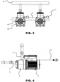
- reference number 1 globally and schematically indicates a pressurization system, made according to the present invention.
- Figures 1 to 4 represent in particular a pressurization system 1 comprising two hydraulic pumps 2.
- This embodiment is exemplary and non-limiting of the scope of protection defined by the attached claims, as it will also be more apparent herebelow.
- the pressurization system 1 can provide a number np of associated hydraulic pumps 2.
- Each hydraulic pump 2 comprises an electric motor 3 and a hydraulic unit 4.
- Each hydraulic pump 2 comprises an electronic control unit 5.
- the electric motor 3 and the hydraulic unit 4 are kinematically coupled by means of a driving shaft (not shown).
- the electric motor 3 is preferably of the asynchronous two-phase type.
- the electric motor 3, in the exemplary embodiment of Figure 1 is laterally coupled to the electronic control unit 5.
- the electronic control unit 5 comprises an electronic control board (not shown) and an interface display 10.
- the electronic control unit is powered by means of a connecting cable 11.
- the electronic control unit 5 further comprises a pressure sensor (not shown), connected to the electronic control board.
- the pressure sensor is adapted to detect the pressure of the liquid inside the liquid delivery duct 7, and therefore to adjust the start/stop cycles of the pressurization system 1.
- Each hydraulic pump 2 comprises a pressure sensor.
- the electric motor 3 is cooled by means of a cooling fan 12 splined to the driving shaft at a rear closure 13.
- the cooling fan 12 is accommodated in a ventilated housing 14, coupled to the rear closure 13.
- the electronic control unit 5 is adapted to manage and control at least one operating parameter of the hydraulic pump 2 of the pressurization system 1, in particular by means of the detections of the pressure sensor integrated in the structure of the hydraulic pump 2.
- the variables managed and controlled by the electronic unit 5 comprise particularly, but not exclusively, the manometric pressure Hs measured by the pressure sensor of each hydraulic pump 2, the plant minimum pressure Hmin set by the user, the plant maximum pressure Hmax set by the user, a time unit ⁇ t fixed equal for each hydraulic pump 2 in the installation step.
- the electronic control unit 5 associates an individual temporary number Np with each hydraulic pump 2, which is variable from 1 to np, np being variable depending on the specific case, and an individual index n for each hydraulic pump 2.
- a waiting time Tatt is determined, which is related to the time shift with which a sequential switching on or off of the hydraulic pumps 2 of the pressurization system 1 occurs.
- a correction constant Kpc is also associated with the waiting time Tatt.
- This correction constant Kpc performs a predictive correction based on the evolution of the value of the first derivative and of the sign of the second derivative of the function interpolating the pressure measured by the sensor of each hydraulic pump 2.
- the values of the correction constant Kpc are storable in tables which can be modified in the installation step of the pressurization system 1. If distributed withdrawals by the users occur the value of Kpc is comprised between zero and one. On the contrary, in case of detection of very small withdrawals with minimum pressure losses, for example under dripping conditions, the value of Kpc is much greater than 1.
- TattNp Kpc * Np * ⁇ t.
- a step of calibrating the pressurization system 1 follows at the end of the step of installing and setting parameters.
- the pressurization system 1 is pressurized at the maximum pressure Hmax.
- the maximum pressure Hmax is measured by any hydraulic pump 2 comprised between the np hydraulic pumps of the pressurization system 1.
- This hydraulic pump 2 is thus set as the reference hydraulic pump of the system and all the pressures measured by the sensors of each pump of the pressurization unit are defined as Hmax.
- This calibration step allows possible calibration deviations of the pressure sensors of each hydraulic pump 2 to be avoided.
- a similar calibration step can be further set regarding the minimum pressure Hmin.
- the correction parameter Kpc is set equal to one.
- a step of defining an operating range is provided, defined by the maximum pressure Hmax and by the minimum pressure Hmin, which are common to all the hydraulic pumps 2 of the pressurization system 1.
- An individual temporary number Np comprised between 1 and np is associated with the hydraulic pumps 2 which are different from the reference hydraulic pump.
- each pressure sensor Upon starting the pressurization system 1 each pressure sensor detects the manometric pressure Hs and the electronic control unit 5 determines the function interpolating the trend of the manometric pressure Hs and the first and second derivatives of this interpolating function.
- the hydraulic pump 2 corresponding to the value one of Np is started and stays on until the manometric pressure Hs is higher than the maximum pressure Hmax.
- a value which is higher than one is allocated to the correction constant Kpc, selected between the listed values as a function of the slope of the function of the detected manometric pressure Hs.
- the hydraulic pump 2 corresponding to the value one of Np is bringing the pressure back to reference conditions providing the users with a delivery complying with the plant specifications.
- first and second derivatives indicate that the pressure in the circuit is decreasing a value which is lower than one is allocated to the correction constant Kpc, selected between the listed values as a function of the slope of the function of the detected manometric pressure Hs.
- the described first embodiment is particularly effective in equally distributing wear in the mechatronic components of the hydraulic pumps 2.
- Fig. 5 the diagram of operation and performances of the pressurization system 1 provided with np pumps of the just described type is represented in a graph Q/H, where Q is the flow rate required to the pressurization implant and H the relevant hydraulic head. Curves of operation with steady, proportional and quadratic H are further represented.
- the individual temporary number Np comprised between the values one and np is generated and associated in a random manner with each pump, and for each of them the electronic control unit 5 calculates the waiting time parameter TattNp as described.
- a step of switching on and off the pumps which is similar to the one provided in the first embodiment then follows.
- the variable defined as "shift”, i.e. a threshold constant, is set, being required to define the switching on and off ranges of each hydraulic pump 2.
- the definition of the switching on and off ranges is detected and determined by means of a time counter.
- a minimum operating range x between the switching on pressure and the switching off one of each hydraulic pump 2 is set, in order to carry out an optimal distribution of the switching on time of each hydraulic pump 2 and reduce the number of starts per hour.
- the minimum range x is generally, but not limitedly, fixed between 1 and 1.5 bar.
- Each hydraulic pump 2 is identified by means of an identification index ID.
- a threshold constant "shift" that is greater than t and equal for all the hydraulic pumps 2 is fixed. For each hydraulic pump 2 the switching on pressure Pstart, stop pressure Pstop values and the number of pumps np are set.
- Each pump based on the identification index ID thereof set by the user, is set according to its own i-th thresholds, so as to equally split the operating pressure ranges.
- an alternation of operation of the hydraulic pumps 2 is obtained by suitably swapping the reference index ID of each of them.
- a supply network voltage period of the pressurization unit 1 as a clock function is preferably used as a synchronising signal for swapping the identification index ID.
- the supply network voltage period is measured by calculating the sinusoidal voltage peaks. The preferred but not exclusive selection of this signal makes the synchronism very strong since, even in case of fluctuation of the network frequency, the hydraulic pumps would stay synchronized, being all exposed to the same fluctuation.
- the operating time of the single hydraulic pump 2 is calculated and the index ID swapping is suitably selected accordingly.
- a pressurization system 1 not belonging to the claimed invention, is represented, comprising three hydraulic pumps 2, of which a reference hydraulic pump 2 and two interlocked hydraulic pumps 15 powered by the electronic control unit 5 of this hydraulic pump 2 operating with one of the above-described methods.
- the interlocked hydraulic pumps 15 are connected to the single reference hydraulic pump 2 by means of connecting pipes 16.
- the present invention allows the number of drives of the pressurization system to be minimized thereby protecting the electromechanical devices being involved.
- the method according to the invention allows only one measured physical parameter to be adopted, such as pressure, minimizing problems deriving from possible measurement errors.
- the present invention allows a highly efficient pressurization system with mutually independent hydraulic pumps to be created in a cost-effective way.
Landscapes
- Engineering & Computer Science (AREA)
- Mechanical Engineering (AREA)
- General Engineering & Computer Science (AREA)
- Computer Hardware Design (AREA)
- Control Of Positive-Displacement Pumps (AREA)
- Press Drives And Press Lines (AREA)
Claims (2)
- Antriebsschutz- und Verwaltungsverfahren für ein Druckbeaufschlagungssystem (1), umfassend mindestens zwei operativ unabhängige hydraulische Pumpen (2), wobei das Verfahren die folgenden Schritte umfasst:- Einstellen einer Vielzahl von vordefinierten Parametern durch einen Benutzer anhand einer elektronischen Steuereinheit (5) an jeder der hydraulischen Pumpen (2); wobei die Parameter mindestens einen Mindestdruck (Hmin) und einen Höchstdruck (Hmax) umfassen;- Detektieren mindestens eines manometrischen Druckwerts (Hs) anhand mindestens eines Drucksensors an einer Zufuhrleitung (7) jeder der hydraulischen Pumpen (2);- Bestimmen eines Antriebs in einer sequentiellen und/oder synchronisierten Art der mindestens zwei hydraulischen Pumpen (2), das die folgenden Schritte umfasst:- Schritt 1 -
Assoziieren einer individuellen temporären Zahl (Np) mit jeder hydraulischen Pumpe (2), die variabel zwischen 1 und np ist, wobei np die Zahl der mindestens zwei operativ unabhängigen Pumpen (2) ist;- Schritt 2 -
jeder Drucksensor detektiert den manometrischen Druck (Hs) und die elektronische Steuereinheit (5) bestimmt den Trend des manometrischen Drucks (Hs) und der ersten und zweiten Ableitung des manometrischen Drucks (Hs);- Schritt 3 -
wenn der Wert des manometrischen Drucks (Hs) niedriger ist als der Mindestdruck (Hmin), läuft die hydraulische Pumpe (2), die dem Wert eins von (Np) entspricht, an;- Schritt 4 -
Identifizieren und Einstellen einer Wartezeit (Tatt) in einem sequentiellen Antrieb der mindestens zwei operativ unabhängigen hydraulischen Pumpen (2);- Schritt 5 -
wenn die erste und zweite Ableitung anzeigen, dass der manometrische Druck (Hs) in dem Kreislauf ansteigt, wird keine weitere Maßnahme ergriffen;- Schritt 6 -
wenn die erste und zweite Ableitung anzeigen, dass der manometrische Druck (Hs) in dem Kreislauf fällt, sobald die Wartezeit (Tatt) abgelaufen ist, schaltet die hydraulische Pumpe (2) mit der nächsten individuellen temporären Zahl (Np) ebenfalls ein;- Schritt 7 -
Wiederholen von Schritt 2 bis 6, bis der manometrische Druck (Hs) den Höchstdruck (Hmax) erreicht oder bis alle hydraulischen Pumpen (2) eingeschaltet sind;- sobald der manometrische Druck (Hs), gemessen von dem Drucksensor in jeder Pumpe, höher als oder gleich dem Höchstdruck (Hmax) ist, schalten alle hydraulischen Pumpen (2) ab und die individuelle temporäre Zahl (Np) wird wie folgt aktualisiert:- Wenn Np = np wird Np = 1 eingestellt- Wenn Np = n wird Np = n + 1 eingestellt- Wiederaufnahme bei Schritt 2. - Antriebsschutz- und Verwaltungsverfahren für ein Druckbeaufschlagungssystem (1) nach Anspruch 1, ferner umfassend einen Schritt zum Korrigieren der Wartezeit anhand einer Korrekturkonstante (Kpc), die in der elektronischen Steuereinheit (5) an jeder der hydraulischen Pumpen (2) eingestellt wird.
Applications Claiming Priority (1)
| Application Number | Priority Date | Filing Date | Title |
|---|---|---|---|
| IT102019000015674A IT201900015674A1 (it) | 2019-09-05 | 2019-09-05 | Metodo di protezione e di gestione di azionamento di un sistema di pressurizzazione |
Publications (2)
| Publication Number | Publication Date |
|---|---|
| EP3789615A1 EP3789615A1 (de) | 2021-03-10 |
| EP3789615B1 true EP3789615B1 (de) | 2024-05-29 |
Family
ID=69173230
Family Applications (1)
| Application Number | Title | Priority Date | Filing Date |
|---|---|---|---|
| EP20194118.4A Active EP3789615B1 (de) | 2019-09-05 | 2020-09-02 | Antriebsschutz- und verwaltungsverfahren für ein drucksystem |
Country Status (4)
| Country | Link |
|---|---|
| US (1) | US11994134B2 (de) |
| EP (1) | EP3789615B1 (de) |
| CN (1) | CN112443490B (de) |
| IT (1) | IT201900015674A1 (de) |
Families Citing this family (2)
| Publication number | Priority date | Publication date | Assignee | Title |
|---|---|---|---|---|
| IT201900009747A1 (it) * | 2019-06-21 | 2020-12-21 | Calpeda A Spa | Metodo di gestione e controllo di un sistema di pressurizzazione |
| CN119900701B (zh) * | 2024-12-29 | 2025-11-18 | 中国航空工业集团公司西安航空计算技术研究所 | 用于电动泵及传动系统的多余度控制方法及系统 |
Family Cites Families (13)
| Publication number | Priority date | Publication date | Assignee | Title |
|---|---|---|---|---|
| DE2756916C2 (de) * | 1977-12-21 | 1985-09-26 | Danfoss A/S, Nordborg | Vorrichtung zur Einrichtung der Fördermenge einer Wasserwerk-Pumpenanordnung |
| KR950008533B1 (ko) * | 1991-11-30 | 1995-07-31 | 삼성중공업주식회사 | 유압펌프의 토출유량 제어장치 |
| US5846056A (en) * | 1995-04-07 | 1998-12-08 | Dhindsa; Jasbir S. | Reciprocating pump system and method for operating same |
| JP3561667B2 (ja) * | 1999-11-18 | 2004-09-02 | 新キャタピラー三菱株式会社 | 油圧ポンプの制御装置 |
| JP2004150402A (ja) * | 2002-11-01 | 2004-05-27 | Hitachi High-Technologies Corp | 液体クロマトグラフ用ポンプ |
| JP5010504B2 (ja) * | 2008-02-29 | 2012-08-29 | 株式会社東芝 | 配水圧力最適制御装置 |
| EP2476907B1 (de) * | 2011-01-14 | 2014-08-06 | Grundfos Management a/s | System und Verfahren zur Drucksteuerung in einem Netzwerk |
| FI127255B (en) * | 2011-11-02 | 2018-02-15 | Abb Technology Oy | Method and controller for operating the pump system |
| EP2778296B1 (de) | 2013-03-11 | 2018-04-25 | Grundfos Holding A/S | Pumpensystem |
| AU2013204013B2 (en) * | 2013-03-15 | 2015-09-10 | Franklin Electric Company, Inc. | System and method for operating a pump |
| CN105392556B (zh) * | 2014-01-14 | 2017-05-10 | 三菱重工压缩机有限公司 | 升压系统及气体的升压方法 |
| ES2620685B1 (es) * | 2016-10-18 | 2018-04-12 | Coelbo Control System, S.L. | Sistema que comprende dos o más bombas conectadas en paralelo y presostato concebido para operar en dicho sistema |
| EP3242035B1 (de) * | 2016-12-28 | 2021-08-18 | Grundfos Holding A/S | Verfahren zum betreiben mindestens eines pumpenaggregates von einer vielzahl von pumpenaggregaten |
-
2019
- 2019-09-05 IT IT102019000015674A patent/IT201900015674A1/it unknown
-
2020
- 2020-09-02 EP EP20194118.4A patent/EP3789615B1/de active Active
- 2020-09-04 US US17/012,459 patent/US11994134B2/en active Active
- 2020-09-04 CN CN202010920502.1A patent/CN112443490B/zh active Active
Also Published As
| Publication number | Publication date |
|---|---|
| US20210071673A1 (en) | 2021-03-11 |
| CN112443490B (zh) | 2025-05-06 |
| IT201900015674A1 (it) | 2021-03-05 |
| CN112443490A (zh) | 2021-03-05 |
| EP3789615A1 (de) | 2021-03-10 |
| US11994134B2 (en) | 2024-05-28 |
Similar Documents
| Publication | Publication Date | Title |
|---|---|---|
| EP3789615B1 (de) | Antriebsschutz- und verwaltungsverfahren für ein drucksystem | |
| US7873489B2 (en) | Dialysis machine with servicing indicator | |
| JP7234215B2 (ja) | ポンプ・関節間高度レベルのユーザインターフェース、関節高度の自動較正、及び関節圧力推定 | |
| US4945491A (en) | Monitor and control for a multi-pump system | |
| US20070177985A1 (en) | Integral sensor and control for dry run and flow fault protection of a pump | |
| MX2010006270A (es) | Sistema y metodo de seguridad para bomba y motor. | |
| MX2010006269A (es) | Metodo para controlar una bomba y motor. | |
| KR101972627B1 (ko) | 급수 장치, 급수 방법, 급수 장치의 제어 장치 및 급수 장치의 제어 프로그램을 기록한 컴퓨터로 읽을 수 있는 매체 | |
| EP1261900A1 (de) | Verfahren und vorrichtiung zur automatischen steuereung des wasserstandes in einem tank mittels eines drahtlosen steuerungsverfahren | |
| US20140119953A1 (en) | Method for controlling at least a part of a pump station | |
| JP5823348B2 (ja) | 給水ポンプ装置 | |
| JP2020143626A (ja) | 給水装置 | |
| JP6809367B2 (ja) | 油圧ポンプ異常診断装置 | |
| JP6759392B2 (ja) | 給水装置 | |
| CN106150998A (zh) | 泵装置、远程监视装置及泵装置的控制方法 | |
| EP2990652A1 (de) | Pumpvorrichtung | |
| JPH08159078A (ja) | 少水量停止機能付回転数制御給水システム | |
| US11365739B2 (en) | Management and control method of a pressurization system | |
| KR101448888B1 (ko) | 인버터 부스터 펌프의 제어방법 | |
| KR20000046873A (ko) | 부스터 펌프 시스템의 토출압력센서의 레퍼런스 설정방법 | |
| CN121433351A (zh) | 一种气压补偿控制方法、装置、电器设备及存储介质 | |
| KR20170073061A (ko) | 펌프성능 데이터 베이스에 의한 인버터 전압-주파수 패턴 능동제어방법 | |
| JPH05157088A (ja) | 自動給水装置の制御方法 | |
| CN117006542A (zh) | 用于确定空调室外机安装位置的方法及装置、空调室外机 | |
| JP2015194156A (ja) | ポンプ運転台数制御方法およびポンプ装置 |
Legal Events
| Date | Code | Title | Description |
|---|---|---|---|
| PUAI | Public reference made under article 153(3) epc to a published international application that has entered the european phase |
Free format text: ORIGINAL CODE: 0009012 |
|
| STAA | Information on the status of an ep patent application or granted ep patent |
Free format text: STATUS: THE APPLICATION HAS BEEN PUBLISHED |
|
| AK | Designated contracting states |
Kind code of ref document: A1 Designated state(s): AL AT BE BG CH CY CZ DE DK EE ES FI FR GB GR HR HU IE IS IT LI LT LU LV MC MK MT NL NO PL PT RO RS SE SI SK SM TR |
|
| AX | Request for extension of the european patent |
Extension state: BA ME |
|
| STAA | Information on the status of an ep patent application or granted ep patent |
Free format text: STATUS: REQUEST FOR EXAMINATION WAS MADE |
|
| 17P | Request for examination filed |
Effective date: 20210909 |
|
| RBV | Designated contracting states (corrected) |
Designated state(s): AL AT BE BG CH CY CZ DE DK EE ES FI FR GB GR HR HU IE IS IT LI LT LU LV MC MK MT NL NO PL PT RO RS SE SI SK SM TR |
|
| GRAP | Despatch of communication of intention to grant a patent |
Free format text: ORIGINAL CODE: EPIDOSNIGR1 |
|
| STAA | Information on the status of an ep patent application or granted ep patent |
Free format text: STATUS: GRANT OF PATENT IS INTENDED |
|
| INTG | Intention to grant announced |
Effective date: 20231220 |
|
| P01 | Opt-out of the competence of the unified patent court (upc) registered |
Effective date: 20240219 |
|
| GRAS | Grant fee paid |
Free format text: ORIGINAL CODE: EPIDOSNIGR3 |
|
| GRAA | (expected) grant |
Free format text: ORIGINAL CODE: 0009210 |
|
| STAA | Information on the status of an ep patent application or granted ep patent |
Free format text: STATUS: THE PATENT HAS BEEN GRANTED |
|
| AK | Designated contracting states |
Kind code of ref document: B1 Designated state(s): AL AT BE BG CH CY CZ DE DK EE ES FI FR GB GR HR HU IE IS IT LI LT LU LV MC MK MT NL NO PL PT RO RS SE SI SK SM TR |
|
| REG | Reference to a national code |
Ref country code: CH Ref legal event code: EP |
|
| REG | Reference to a national code |
Ref country code: IE Ref legal event code: FG4D |
|
| REG | Reference to a national code |
Ref country code: DE Ref legal event code: R096 Ref document number: 602020031550 Country of ref document: DE |
|
| REG | Reference to a national code |
Ref country code: LT Ref legal event code: MG9D |
|
| REG | Reference to a national code |
Ref country code: NL Ref legal event code: MP Effective date: 20240529 |
|
| PG25 | Lapsed in a contracting state [announced via postgrant information from national office to epo] |
Ref country code: IS Free format text: LAPSE BECAUSE OF FAILURE TO SUBMIT A TRANSLATION OF THE DESCRIPTION OR TO PAY THE FEE WITHIN THE PRESCRIBED TIME-LIMIT Effective date: 20240929 |
|
| PG25 | Lapsed in a contracting state [announced via postgrant information from national office to epo] |
Ref country code: BG Free format text: LAPSE BECAUSE OF FAILURE TO SUBMIT A TRANSLATION OF THE DESCRIPTION OR TO PAY THE FEE WITHIN THE PRESCRIBED TIME-LIMIT Effective date: 20240529 |
|
| PG25 | Lapsed in a contracting state [announced via postgrant information from national office to epo] |
Ref country code: FI Free format text: LAPSE BECAUSE OF FAILURE TO SUBMIT A TRANSLATION OF THE DESCRIPTION OR TO PAY THE FEE WITHIN THE PRESCRIBED TIME-LIMIT Effective date: 20240529 Ref country code: HR Free format text: LAPSE BECAUSE OF FAILURE TO SUBMIT A TRANSLATION OF THE DESCRIPTION OR TO PAY THE FEE WITHIN THE PRESCRIBED TIME-LIMIT Effective date: 20240529 |
|
| PG25 | Lapsed in a contracting state [announced via postgrant information from national office to epo] |
Ref country code: GR Free format text: LAPSE BECAUSE OF FAILURE TO SUBMIT A TRANSLATION OF THE DESCRIPTION OR TO PAY THE FEE WITHIN THE PRESCRIBED TIME-LIMIT Effective date: 20240830 |
|
| REG | Reference to a national code |
Ref country code: AT Ref legal event code: MK05 Ref document number: 1690868 Country of ref document: AT Kind code of ref document: T Effective date: 20240529 |
|
| PG25 | Lapsed in a contracting state [announced via postgrant information from national office to epo] |
Ref country code: ES Free format text: LAPSE BECAUSE OF FAILURE TO SUBMIT A TRANSLATION OF THE DESCRIPTION OR TO PAY THE FEE WITHIN THE PRESCRIBED TIME-LIMIT Effective date: 20240529 |
|
| PG25 | Lapsed in a contracting state [announced via postgrant information from national office to epo] |
Ref country code: AT Free format text: LAPSE BECAUSE OF FAILURE TO SUBMIT A TRANSLATION OF THE DESCRIPTION OR TO PAY THE FEE WITHIN THE PRESCRIBED TIME-LIMIT Effective date: 20240529 |
|
| PG25 | Lapsed in a contracting state [announced via postgrant information from national office to epo] |
Ref country code: PL Free format text: LAPSE BECAUSE OF FAILURE TO SUBMIT A TRANSLATION OF THE DESCRIPTION OR TO PAY THE FEE WITHIN THE PRESCRIBED TIME-LIMIT Effective date: 20240529 |
|
| PG25 | Lapsed in a contracting state [announced via postgrant information from national office to epo] |
Ref country code: LV Free format text: LAPSE BECAUSE OF FAILURE TO SUBMIT A TRANSLATION OF THE DESCRIPTION OR TO PAY THE FEE WITHIN THE PRESCRIBED TIME-LIMIT Effective date: 20240529 |
|
| PG25 | Lapsed in a contracting state [announced via postgrant information from national office to epo] |
Ref country code: PL Free format text: LAPSE BECAUSE OF FAILURE TO SUBMIT A TRANSLATION OF THE DESCRIPTION OR TO PAY THE FEE WITHIN THE PRESCRIBED TIME-LIMIT Effective date: 20240529 Ref country code: NO Free format text: LAPSE BECAUSE OF FAILURE TO SUBMIT A TRANSLATION OF THE DESCRIPTION OR TO PAY THE FEE WITHIN THE PRESCRIBED TIME-LIMIT Effective date: 20240829 Ref country code: LV Free format text: LAPSE BECAUSE OF FAILURE TO SUBMIT A TRANSLATION OF THE DESCRIPTION OR TO PAY THE FEE WITHIN THE PRESCRIBED TIME-LIMIT Effective date: 20240529 Ref country code: IS Free format text: LAPSE BECAUSE OF FAILURE TO SUBMIT A TRANSLATION OF THE DESCRIPTION OR TO PAY THE FEE WITHIN THE PRESCRIBED TIME-LIMIT Effective date: 20240929 Ref country code: HR Free format text: LAPSE BECAUSE OF FAILURE TO SUBMIT A TRANSLATION OF THE DESCRIPTION OR TO PAY THE FEE WITHIN THE PRESCRIBED TIME-LIMIT Effective date: 20240529 Ref country code: GR Free format text: LAPSE BECAUSE OF FAILURE TO SUBMIT A TRANSLATION OF THE DESCRIPTION OR TO PAY THE FEE WITHIN THE PRESCRIBED TIME-LIMIT Effective date: 20240830 Ref country code: FI Free format text: LAPSE BECAUSE OF FAILURE TO SUBMIT A TRANSLATION OF THE DESCRIPTION OR TO PAY THE FEE WITHIN THE PRESCRIBED TIME-LIMIT Effective date: 20240529 Ref country code: ES Free format text: LAPSE BECAUSE OF FAILURE TO SUBMIT A TRANSLATION OF THE DESCRIPTION OR TO PAY THE FEE WITHIN THE PRESCRIBED TIME-LIMIT Effective date: 20240529 Ref country code: BG Free format text: LAPSE BECAUSE OF FAILURE TO SUBMIT A TRANSLATION OF THE DESCRIPTION OR TO PAY THE FEE WITHIN THE PRESCRIBED TIME-LIMIT Effective date: 20240529 Ref country code: AT Free format text: LAPSE BECAUSE OF FAILURE TO SUBMIT A TRANSLATION OF THE DESCRIPTION OR TO PAY THE FEE WITHIN THE PRESCRIBED TIME-LIMIT Effective date: 20240529 Ref country code: RS Free format text: LAPSE BECAUSE OF FAILURE TO SUBMIT A TRANSLATION OF THE DESCRIPTION OR TO PAY THE FEE WITHIN THE PRESCRIBED TIME-LIMIT Effective date: 20240829 |
|
| PG25 | Lapsed in a contracting state [announced via postgrant information from national office to epo] |
Ref country code: NL Free format text: LAPSE BECAUSE OF FAILURE TO SUBMIT A TRANSLATION OF THE DESCRIPTION OR TO PAY THE FEE WITHIN THE PRESCRIBED TIME-LIMIT Effective date: 20240529 |
|
| PG25 | Lapsed in a contracting state [announced via postgrant information from national office to epo] |
Ref country code: NL Free format text: LAPSE BECAUSE OF FAILURE TO SUBMIT A TRANSLATION OF THE DESCRIPTION OR TO PAY THE FEE WITHIN THE PRESCRIBED TIME-LIMIT Effective date: 20240529 |
|
| PG25 | Lapsed in a contracting state [announced via postgrant information from national office to epo] |
Ref country code: DK Free format text: LAPSE BECAUSE OF FAILURE TO SUBMIT A TRANSLATION OF THE DESCRIPTION OR TO PAY THE FEE WITHIN THE PRESCRIBED TIME-LIMIT Effective date: 20240529 |
|
| PG25 | Lapsed in a contracting state [announced via postgrant information from national office to epo] |
Ref country code: EE Free format text: LAPSE BECAUSE OF FAILURE TO SUBMIT A TRANSLATION OF THE DESCRIPTION OR TO PAY THE FEE WITHIN THE PRESCRIBED TIME-LIMIT Effective date: 20240529 |
|
| PG25 | Lapsed in a contracting state [announced via postgrant information from national office to epo] |
Ref country code: CZ Free format text: LAPSE BECAUSE OF FAILURE TO SUBMIT A TRANSLATION OF THE DESCRIPTION OR TO PAY THE FEE WITHIN THE PRESCRIBED TIME-LIMIT Effective date: 20240529 |
|
| PG25 | Lapsed in a contracting state [announced via postgrant information from national office to epo] |
Ref country code: SK Free format text: LAPSE BECAUSE OF FAILURE TO SUBMIT A TRANSLATION OF THE DESCRIPTION OR TO PAY THE FEE WITHIN THE PRESCRIBED TIME-LIMIT Effective date: 20240529 Ref country code: RO Free format text: LAPSE BECAUSE OF FAILURE TO SUBMIT A TRANSLATION OF THE DESCRIPTION OR TO PAY THE FEE WITHIN THE PRESCRIBED TIME-LIMIT Effective date: 20240529 |
|
| PG25 | Lapsed in a contracting state [announced via postgrant information from national office to epo] |
Ref country code: SM Free format text: LAPSE BECAUSE OF FAILURE TO SUBMIT A TRANSLATION OF THE DESCRIPTION OR TO PAY THE FEE WITHIN THE PRESCRIBED TIME-LIMIT Effective date: 20240529 |
|
| PG25 | Lapsed in a contracting state [announced via postgrant information from national office to epo] |
Ref country code: SM Free format text: LAPSE BECAUSE OF FAILURE TO SUBMIT A TRANSLATION OF THE DESCRIPTION OR TO PAY THE FEE WITHIN THE PRESCRIBED TIME-LIMIT Effective date: 20240529 Ref country code: SK Free format text: LAPSE BECAUSE OF FAILURE TO SUBMIT A TRANSLATION OF THE DESCRIPTION OR TO PAY THE FEE WITHIN THE PRESCRIBED TIME-LIMIT Effective date: 20240529 Ref country code: RO Free format text: LAPSE BECAUSE OF FAILURE TO SUBMIT A TRANSLATION OF THE DESCRIPTION OR TO PAY THE FEE WITHIN THE PRESCRIBED TIME-LIMIT Effective date: 20240529 Ref country code: EE Free format text: LAPSE BECAUSE OF FAILURE TO SUBMIT A TRANSLATION OF THE DESCRIPTION OR TO PAY THE FEE WITHIN THE PRESCRIBED TIME-LIMIT Effective date: 20240529 Ref country code: DK Free format text: LAPSE BECAUSE OF FAILURE TO SUBMIT A TRANSLATION OF THE DESCRIPTION OR TO PAY THE FEE WITHIN THE PRESCRIBED TIME-LIMIT Effective date: 20240529 Ref country code: CZ Free format text: LAPSE BECAUSE OF FAILURE TO SUBMIT A TRANSLATION OF THE DESCRIPTION OR TO PAY THE FEE WITHIN THE PRESCRIBED TIME-LIMIT Effective date: 20240529 |
|
| REG | Reference to a national code |
Ref country code: DE Ref legal event code: R097 Ref document number: 602020031550 Country of ref document: DE |
|
| PLBE | No opposition filed within time limit |
Free format text: ORIGINAL CODE: 0009261 |
|
| STAA | Information on the status of an ep patent application or granted ep patent |
Free format text: STATUS: NO OPPOSITION FILED WITHIN TIME LIMIT |
|
| PG25 | Lapsed in a contracting state [announced via postgrant information from national office to epo] |
Ref country code: SI Free format text: LAPSE BECAUSE OF FAILURE TO SUBMIT A TRANSLATION OF THE DESCRIPTION OR TO PAY THE FEE WITHIN THE PRESCRIBED TIME-LIMIT Effective date: 20240529 Ref country code: MC Free format text: LAPSE BECAUSE OF FAILURE TO SUBMIT A TRANSLATION OF THE DESCRIPTION OR TO PAY THE FEE WITHIN THE PRESCRIBED TIME-LIMIT Effective date: 20240529 |
|
| REG | Reference to a national code |
Ref country code: CH Ref legal event code: PL |
|
| 26N | No opposition filed |
Effective date: 20250303 |
|
| PG25 | Lapsed in a contracting state [announced via postgrant information from national office to epo] |
Ref country code: LU Free format text: LAPSE BECAUSE OF NON-PAYMENT OF DUE FEES Effective date: 20240902 |
|
| GBPC | Gb: european patent ceased through non-payment of renewal fee |
Effective date: 20240902 |
|
| PG25 | Lapsed in a contracting state [announced via postgrant information from national office to epo] |
Ref country code: GB Free format text: LAPSE BECAUSE OF NON-PAYMENT OF DUE FEES Effective date: 20240902 |
|
| REG | Reference to a national code |
Ref country code: BE Ref legal event code: MM Effective date: 20240930 |
|
| PG25 | Lapsed in a contracting state [announced via postgrant information from national office to epo] |
Ref country code: BE Free format text: LAPSE BECAUSE OF NON-PAYMENT OF DUE FEES Effective date: 20240930 |
|
| PG25 | Lapsed in a contracting state [announced via postgrant information from national office to epo] |
Ref country code: CH Free format text: LAPSE BECAUSE OF NON-PAYMENT OF DUE FEES Effective date: 20240930 |
|
| PG25 | Lapsed in a contracting state [announced via postgrant information from national office to epo] |
Ref country code: IE Free format text: LAPSE BECAUSE OF NON-PAYMENT OF DUE FEES Effective date: 20240902 |
|
| PG25 | Lapsed in a contracting state [announced via postgrant information from national office to epo] |
Ref country code: SE Free format text: LAPSE BECAUSE OF FAILURE TO SUBMIT A TRANSLATION OF THE DESCRIPTION OR TO PAY THE FEE WITHIN THE PRESCRIBED TIME-LIMIT Effective date: 20240529 |
|
| PGFP | Annual fee paid to national office [announced via postgrant information from national office to epo] |
Ref country code: DE Payment date: 20250820 Year of fee payment: 6 |
|
| PGFP | Annual fee paid to national office [announced via postgrant information from national office to epo] |
Ref country code: IT Payment date: 20250925 Year of fee payment: 6 |
|
| PGFP | Annual fee paid to national office [announced via postgrant information from national office to epo] |
Ref country code: FR Payment date: 20250820 Year of fee payment: 6 |
|
| PG25 | Lapsed in a contracting state [announced via postgrant information from national office to epo] |
Ref country code: PT Free format text: LAPSE BECAUSE OF NON-PAYMENT OF DUE FEES Effective date: 20240529 |
|
| PG25 | Lapsed in a contracting state [announced via postgrant information from national office to epo] |
Ref country code: CY Free format text: LAPSE BECAUSE OF FAILURE TO SUBMIT A TRANSLATION OF THE DESCRIPTION OR TO PAY THE FEE WITHIN THE PRESCRIBED TIME-LIMIT; INVALID AB INITIO Effective date: 20200902 |
|
| PG25 | Lapsed in a contracting state [announced via postgrant information from national office to epo] |
Ref country code: HU Free format text: LAPSE BECAUSE OF FAILURE TO SUBMIT A TRANSLATION OF THE DESCRIPTION OR TO PAY THE FEE WITHIN THE PRESCRIBED TIME-LIMIT; INVALID AB INITIO Effective date: 20200902 |