EP3789281A1 - Automatically operating vehicle body unloading system - Google Patents
Automatically operating vehicle body unloading system Download PDFInfo
- Publication number
- EP3789281A1 EP3789281A1 EP19195283.7A EP19195283A EP3789281A1 EP 3789281 A1 EP3789281 A1 EP 3789281A1 EP 19195283 A EP19195283 A EP 19195283A EP 3789281 A1 EP3789281 A1 EP 3789281A1
- Authority
- EP
- European Patent Office
- Prior art keywords
- vehicle
- hanger arm
- hanger
- unloading
- actuator
- Prior art date
- Legal status (The legal status is an assumption and is not a legal conclusion. Google has not performed a legal analysis and makes no representation as to the accuracy of the status listed.)
- Granted
Links
Images




Classifications
-
- B—PERFORMING OPERATIONS; TRANSPORTING
- B65—CONVEYING; PACKING; STORING; HANDLING THIN OR FILAMENTARY MATERIAL
- B65G—TRANSPORT OR STORAGE DEVICES, e.g. CONVEYORS FOR LOADING OR TIPPING, SHOP CONVEYOR SYSTEMS OR PNEUMATIC TUBE CONVEYORS
- B65G67/00—Loading or unloading vehicles
- B65G67/02—Loading or unloading land vehicles
- B65G67/24—Unloading land vehicles
-
- B—PERFORMING OPERATIONS; TRANSPORTING
- B62—LAND VEHICLES FOR TRAVELLING OTHERWISE THAN ON RAILS
- B62D—MOTOR VEHICLES; TRAILERS
- B62D65/00—Designing, manufacturing, e.g. assembling, facilitating disassembly, or structurally modifying motor vehicles or trailers, not otherwise provided for
- B62D65/02—Joining sub-units or components to, or positioning sub-units or components with respect to, body shell or other sub-units or components
- B62D65/18—Transportation, conveyor or haulage systems specially adapted for motor vehicle or trailer assembly lines
-
- B—PERFORMING OPERATIONS; TRANSPORTING
- B65—CONVEYING; PACKING; STORING; HANDLING THIN OR FILAMENTARY MATERIAL
- B65G—TRANSPORT OR STORAGE DEVICES, e.g. CONVEYORS FOR LOADING OR TIPPING, SHOP CONVEYOR SYSTEMS OR PNEUMATIC TUBE CONVEYORS
- B65G47/00—Article or material-handling devices associated with conveyors; Methods employing such devices
- B65G47/52—Devices for transferring articles or materials between conveyors i.e. discharging or feeding devices
- B65G47/60—Devices for transferring articles or materials between conveyors i.e. discharging or feeding devices to or from conveyors of the suspended, e.g. trolley, type
- B65G47/61—Devices for transferring articles or materials between conveyors i.e. discharging or feeding devices to or from conveyors of the suspended, e.g. trolley, type for articles
-
- B—PERFORMING OPERATIONS; TRANSPORTING
- B65—CONVEYING; PACKING; STORING; HANDLING THIN OR FILAMENTARY MATERIAL
- B65G—TRANSPORT OR STORAGE DEVICES, e.g. CONVEYORS FOR LOADING OR TIPPING, SHOP CONVEYOR SYSTEMS OR PNEUMATIC TUBE CONVEYORS
- B65G17/00—Conveyors having an endless traction element, e.g. a chain, transmitting movement to a continuous or substantially-continuous load-carrying surface or to a series of individual load-carriers; Endless-chain conveyors in which the chains form the load-carrying surface
- B65G17/30—Details; Auxiliary devices
- B65G17/48—Controlling attitudes of load-carriers during movement
- B65G17/485—Controlling attitudes of load-carriers during movement the load carriers being suspended
-
- B—PERFORMING OPERATIONS; TRANSPORTING
- B65—CONVEYING; PACKING; STORING; HANDLING THIN OR FILAMENTARY MATERIAL
- B65G—TRANSPORT OR STORAGE DEVICES, e.g. CONVEYORS FOR LOADING OR TIPPING, SHOP CONVEYOR SYSTEMS OR PNEUMATIC TUBE CONVEYORS
- B65G2201/00—Indexing codes relating to handling devices, e.g. conveyors, characterised by the type of product or load being conveyed or handled
- B65G2201/02—Articles
- B65G2201/0294—Vehicle bodies
Definitions
- the invention relates to an automatically operating unloading system for unloading an at least partially assembled vehicle from an assembly-line overhead conveyor vehicle carrier and an assembly-line overhead conveyor vehicle carrier comprising such automatically operating unloading system.
- the invention further relates to a method of operating such assembly-line overhead conveyor vehicle carrier for unloading an at least partially assembled vehicle.
- assembly line conveyors of different types, which may be operated at different conveyor speeds, and to transfer vehicles between different assembly-line conveyors.
- assembly line conveyors of different types, which may be operated at different conveyor speeds, and to transfer vehicles between different assembly-line conveyors.
- assembly line conveyor such as a slat assembly line conveyor, a side-mounted assembly line or an overhead assembly line conveyor, which may be a final line conveyor, supporting the vehicle from under its tires.
- US 8,230,988 B2 describes an apparatus for transferring vehicles onto a conveyer.
- the apparatus comprises a front wheel supporting device on an elevator that supports and conveys vehicles by means of wheels, moving vertically with respect to the conveyor, which is provided with a pair of front and rear wheel supporting arms that freely open and close in a horizontal direction between a closed posture supporting front wheels at a predetermined position in terms of the convey direction and an opened posture releasing the front wheels to the convey direction.
- the apparatus further includes a rear wheel supporting device on the elevator, which is provided with a wheel supporting plate that supports rear wheels without determining the position thereof in terms of the convey direction and that can switch its posture between a horizontal posture and a front-down tilted posture in terms of the convey direction.
- the apparatus comprises a posture switching device that changes the wheel supporting plate of the rear wheel supporting device to the tilted posture, at least when the elevator, supporting a vehicle with the wheel supporting arms of the front wheel supporting device in the closed posture and the wheel supporting plate of the rear wheel supporting device in the horizontal posture, is at the lowermost position for transferring the vehicle onto a conveyor.
- US 2006/0032728 A1 describes an apparatus that automatically lifts a vehicle from a continuously moving first conveyor such as an overhead or a side lift vehicle assembly line conveyor carrier so that the vehicle can be stabilized for assembly processes or can be unloaded from the assembly line conveyor.
- An overhead conveyor system may carry partially completed vehicles by carriers. The carriers may be controlled by the overhead conveyor system and can engage and disengage from the vehicle through control signals.
- the apparatus generally consists of a lift shuttle conveyed along guide rails positioned below the vehicle assembly conveyor system and with a lifting mechanism extending upwardly from the lift shuttle. The lifting mechanism rises to engage, stabilize and lift the vehicle from the overhead carrier. Various elevations can be obtained with the lifts to accommodate various processes and product requirements.
- the vertical lifts After traveling along the lift shuttle conveyor, the vertical lifts lower the vehicle to either place the vehicle back on the overhead conveyor carrier or place the vehicle on a second conveyor or such as a floor conveyor where it is moved to further assembly operations or moved to a staging area. The shuttle then returns to its initial position to repeat the process for the next vehicle.
- JP 2008184268 A proposes an elevating/transferring device for transferring a vehicle body of an automobile from a trolley conveyer to a slat conveyor.
- the elevating/conveying means comprises a pair of right and left elevating bodies, a pair of right and left forward/backward moving bodies supported by the elevating bodies, a front wheel supporting means and a rear wheel supporting means disposed to each forward/backward moving body to be switched between a supporting position of an article to be conveyed and a retreated position of an article to be conveyed.
- the elevating/conveying means further includes a driving means for return which moves back the forward/backward moving bodies in a direction reverse to a conveying direction of the slat conveyor to a home position, and a part to be engaged for synchronization disposed to each of the forward/backward moving bodies.
- a synchronizing means comprises a movable body moving in horizontal and vertical directions, a pair of right and left engaging parts for synchronization disposed to the movable body to allow the part to be engaged for synchronization being vertically engaged/disengaged, and a movable body driving means synchronously moving the movable body in the conveying direction of the slat conveyor by a predetermined distance, and then moving back the movable body to the home position.
- a vehicle body transfer apparatus that hangs and transfers a vehicle body of every vehicle type.
- the apparatus includes a hanger that supports the vehicle body in a hanging condition, and moves along a transfer path, and vehicle body support parts that adjust supporting positions on the vehicle body in the hanger based upon a center of gravity of the vehicle body of each vehicle type.
- the hanger are pivotably provided arms at both of right and left sides of an arm support frame. The arms are closed when supporting the vehicle body, and opened to both of right and left sides when releasing the vehicle body, using an open/close mechanism of the hanger.
- the arms when closed, are locked in such a state as to hold the vehicle body, and, when opened, are locked in such a state that the vehicle body is vertically movable with the drop lifter, using an open/close lock mechanism of the hanger.
- the hanger includes center-of-gravity management plates having a plurality of vehicle body support parts that support the vehicle body according to the vehicle type of the vehicle body.
- the apparatus may be applied for transferring vehicle bodies to an overhead conveyor provided in an automotive assembly line for constructing four-wheel automobiles.
- the vehicle body transfer apparatus may comprise an overhead conveyor for hanging and transferring the vehicle body, and a drop lifter having a means for adjusting positions on the vehicle body at which the vehicle body is supported.
- the drop lifter is a relocation means that relocates the vehicle body conveyed through a friction conveyor onto the overhead conveyor.
- the overhead conveyor supports the vehicle body in such a manner that the center of gravity of the vehicle body of every vehicle type and the center of the hanger are substantially aligned (or are precisely aligned) with each other, in order to hang the vehicle body of every vehicle type in a stable condition.
- Various types of sensors may be arranged on the overhead conveyor, such as a sensor that detects the stop position of each hanger body, a sensor which detects the moved position of an engaging lever or the rear hanger arm on each of the engaging grooves of the hanger body, and detects whether the engaging lever can be engaged with or disengaged from each engaging groove, at the moved position.
- the overhead conveyor may be equipped with a sensor which detects whether the engaging lever is being engaged to the engaging groove or not, a sensor which detects whether each of vehicle body supporting parts is supporting the vehicle body, and/or a sensor which detects whether each of rotation arms is opened at the delivery position of the vehicle body.
- Hanger arms of a carrier may be closed when supporting a vehicle body, and may be opened when releasing the vehicle body, using an open/close mechanism of the hanger.
- Such mechanisms may require quite some operational space, particularly to the side, and a drive of the mechanism, a corresponding electric cable or pressure hose connection and the mechanism itself may turn out to be expensive, heavy and have to be carried as well, together with the vehicle.
- manual operation of such open/close mechanisms of a hanger is labor-intensive and may involve a certain risk of injury.
- the object is achieved by an automatically operating unloading system with the features of claim 1 for unloading an at least partially assembled vehicle from an assembly-line overhead conveyor vehicle carrier.
- the object is further achieved by an assembly-line overhead conveyor vehicle carrier with the features of claim 7.
- the object is furthermore achieved by a method according to claim 9 of operating such assembly-line overhead conveyor vehicle carrier for unloading an at least partially assembled vehicle.
- an automatically operating unloading system for unloading an at least partially assembled vehicle from an assembly-line overhead conveyor vehicle carrier.
- the vehicle carrier comprises four hanger arms for supporting the vehicle from underneath, and ends of the hanger arms are pivotally articulated about a perpendicular axis in a lockable manner.
- the unloading system includes at least one rail, a front hanger arm manipulator and a rear hanger arm manipulator.
- the at least one rail is arrangeable at a side of a flat conveying system, parallel to a conveying direction.
- the front hanger arm manipulator and the rear hanger arm manipulator are movably arrangeable on the at least one rail.
- the unloading system further comprises a controllable drive unit for moving the manipulators along the rails, and an electronic control unit.
- each hanger arm manipulator is equipped with at least one controllable actuator
- the electronic control unit is at least configured to control the actuators and to control the drive unit.
- One advantage of the unloading system in accordance with the invention lies in that it can be employed with an assembly-line overhead conveyor vehicle carrier that requires an as little as possible lateral operational space for releasing a carried at least partially assembled vehicle.
- Another advantage of the unloading system lies in that a drive for an open/close mechanism of the assembly-line overhead conveyor vehicle carrier can be omitted as well as a corresponding electric cable or pressure hose connection that would have to be carried with the overhead conveyor vehicle carrier.
- the ends of the hanger arms of the assembly-line overhead conveyor vehicle carrier can be transferred in a fast and reliable manner between a closed position, in which they are arranged for supporting the vehicle from underneath, and an open position, in which there is a lateral clearance to a side of the vehicle that is closest to the respective hanger arm end.
- the invention is applicable with advantage in the automotive sector.
- automotive as used in the present application, shall particularly be understood as being suitable for use with vehicles including passenger cars, transporters, trucks and buses.
- the at least one controllable actuator of each hanger arm manipulator is configured, by control, to linearly push or pull a locking mechanism of one of the hanger arm ends. In this way, the ends of the hanger arms can be unlocked from the closed position in a constructively simple and reliable manner, requiring little hardware effort.
- the at least one controllable actuator of each hanger arm manipulator is alternatively or in addition configured, by control, to rotate one of the hanger arm ends about the perpendicular axis.
- the at least one controllable actuator that is configured to rotate one of the hanger arm ends may be configured to directly rotate one of the hanger arm ends.
- the at least one controllable actuator may alternatively be operatively connected to a gear unit which in turn may be operate fully connected to the hanger arm such that a movement of the at least one controllable actuator is converted into a rotational movement of the hanger arm end.
- the at least one controllable actuator of each hanger arm manipulator is formed by an electric actuator, a pneumatic actuator or a hydraulic actuator.
- the electronic control unit comprises at least one programmable logic controller (PLC).
- PLC programmable logic controller
- the at least one PLC can allow for fast modification of controlling steps, if so required.
- PLCs are also well known for being able to withstand a rough environment in terms of temperature and humidity, such as exist in a factory environment.
- each hanger arm manipulator is equipped with a proximity sensor for sensing a presence of one of the hanger arms to be expected in a predetermined distance range.
- each hanger arm manipulator can automatically be led by the drive unit to a position of one of the hanger arm ends provided that the assembly-line overhead conveyor vehicle carrier drops the at least partially assembled vehicle onto a predetermined position of the flat conveying system within the predetermined distance range.
- the proximity sensor may be formed, without being limited to, by a capacitive sensor, an inductive sensor or an RFID (radio-frequency identification) reading device with an appropriate reading range that is configured for reading an RFID tag attached to one of the hanger arms.
- the proximity sensors of the hanger arm manipulators may be equally designed, but they may also be based on different operating principles.
- an assembly-line overhead conveyor vehicle carrier system in another aspect of the present invention, includes a vehicle carrier having four hanger arms for supporting an at least partially assembled vehicle from underneath. Ends of each of the hanger arms are pivotally articulated about a perpendicular axis in a lockable manner. Further, the assembly-line overhead conveyor vehicle carrier system comprises an automatically operating unloading system in accordance with the invention as disclosed in the present application.
- the at least one rail is arranged at a side of a flat conveying system, and the front hanger arm manipulator and the rear hanger arm manipulator are movably arranged on the at least one rail.
- the ends of the hanger arms are pivotally articulated about a perpendicular axis in a lockable manner such that the ends are at least locked in a closed position in which they are arranged for supporting the vehicle from underneath, and in an open position in which there is a lateral clearance to a side of the vehicle that is closest to the respective hanger arm end.
- a method of operating the proposed assembly-line overhead conveyor vehicle carrier for unloading an at least partially assembled vehicle is provided.
- the method comprises at least the following steps:
- the method further includes the following subsequent steps:
- FIG. 1 schematically shows an assembly-line overhead conveyor vehicle carrier system 10 in accordance with the invention in an elevated side view in a state after unloading a partially assembled vehicle 74.
- the assembly-line overhead conveyor vehicle carrier system 10 is employed for dropping vehicles from an overhead conveyor of a chassis line onto a flat conveying system 76 of a final line, which comprises for example a slat conveyor.
- the vehicles come from the chassis line with tires assembled.
- the assembly-line overhead conveyor vehicle carrier system 10 includes a vehicle carrier 60 having four hanger arms 62 rigidly protruding downwards from ends of two spaced longitudinal beams 64 connected by three spacedly arranged cross beams 66.
- the longitudinal beams 64 are aligned in a conveying direction 78 of the slat conveyor, and are designed to have telescopic ends for adapting to different vehicle lengths.
- the four hanger arms 62 are designed for supporting a partially assembled vehicle 74 from underneath at its chassis. Ends 68 of each of the hanger arms 62 are pivotally articulated about a perpendicular axis 70 in a lockable manner to ensure safe transportation of the vehicle 74.
- the ends 68 of the hanger arms 62 are locked in a closed position in which they are arranged for supporting the vehicle 74 from underneath, and are locked in an open position in which there is a lateral clearance to a side of the partially assembled vehicle 74 that is closest to the respective hanger arm end 68.
- a locking mechanism may include a spring-loaded lock with two locking positions, one in the closed position and one in the open position. Such locking mechanisms are well known to those skilled in the art and therefore need not be discussed in further detail. In Fig. 1 , the ends 68 of the hanger arms 62 are shown in the open position.
- Fig. 2 shows a schematic side view of the assembly-line overhead conveyor vehicle carrier system 10 pursuant to Fig. 1 in a state of dropping a vehicle 74 onto the flat conveying system 76.
- the end 68 of the front hanger arm 62 is locked in an open position, whereas the end 68 of the rear hanger arm 62 is still locked in the closed position.
- the assembly-line overhead conveyor vehicle carrier system 10 further comprises an automatically operating unloading system 12 ( Fig. 1 ).
- the automatically operating unloading system 12 serves for an automatic unloading of the partially assembled vehicle 74 from the vehicle carrier 60.
- the unloading system 12 For each side of the flat conveying system 76, the unloading system 12 includes a rail 14 ( Fig. 3 ) that is arranged along a side of the flat conveying system 76 and parallel to the conveying direction 78, a front hanger arm manipulator 16 and a rear hanger arm manipulator 38 that are movably arranged on the rail 14.
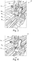
- Fig. 3 shows a schematic elevational view of one of the front hanger arm manipulators 16 of the automatically operating unloading system 12 pursuant to Fig. 1 at the beginning of an unloading process.
- a more detailed perspective view on the front hanger arm manipulator 16 is given in Fig. 5 .
- Fig. 6 shows a schematic elevational view of one of the rear hanger arm manipulators 38 of the automatically operating unloading system 12 pursuant to Fig. 1 at the beginning of the unloading process.
- Fig. 8 A more detailed perspective view on the rear hanger arm manipulator 38 is given in Fig. 8 .
- the front hanger arm manipulators 16 at both sides of the flat conveying system 76 are mirror-inverted versions of each other, as are the rear hanger arm manipulators 38 at both the sides. Thus, it is sufficient to describe the front hanger arm manipulator 16 and the rear hanger arm manipulator 38 of one side only.
- the unloading system 12 is equipped with a controllable drive unit (not shown).
- the controllable drive unit may include an electric motor, which may be operatively coupled to a gear unit, and a control interface.
- the unloading system 12 comprises an electronic control unit 72 ( Fig. 1 ) that is configured for controlling the drive unit via the control interface. Appropriate interface cable or wireless connections are provided (not shown).
- the electronic control unit 72 may comprise a programmable logic controller (PLC), but other electronic control units are as well contemplated.
- PLC programmable logic controller
- both the front hanger arm manipulator 16 and the rear hanger arm manipulator 38 each have a main body 18, 40 that is made from aluminum construction profiles, which allows for cost-effective and stable design of the hanger arm manipulators 16, 38.
- Each hanger arm manipulator 16, 38 is equipped with a plurality of controllable pneumatic actuators, which are configured to be controlled by the electronic control unit 72.
- the main body 18, 40 of the hanger arm manipulators 16, 38 comprises a horizontal part 20, 42 and a vertical part 22, 44.
- the horizontal part 20, 42 is extending horizontally in a lateral direction that is aligned perpendicular to the conveying direction 78.
- the vertical part 22, 44 is slidably arranged on top of the horizontal part 20, 42 to be movable back and forth along the lateral direction by one pneumatic actuator 24, 46 of the plurality of controllable pneumatic actuators 24, 26, 28, 46, 48, 50 that is designed as a linear piston actuator.
- Another controllable pneumatic actuator 26, 48 of each hanger arm manipulator 16, 38, a pushing actuator, is designed as a linear pneumatic piston actuator and is configured, by control, to linearly push the spring-loaded locking mechanism of one of the hanger arm ends 68 for release.
- a further controllable rotation pneumatic actuator 28, 50 of each hanger arm manipulator 16, 38, a rotation actuator is configured, by control, to rotate one of the hanger arm ends 68 about the perpendicular axis 70.
- the rotation actuator may be designed as a power clamp unit comprising a pneumatic cylinder that activates a rotating movement of a clamping arm via a toggle linkage. Such power clamp units are readily commercially available.
- each hanger arm manipulator 16, 38 is equipped with a proximity sensor 30, 52 for sensing a presence of one of the hanger arms 68 that are expected in a predetermined distance range in case that a partially assembled vehicle 74 is being dropped onto the flat conveying system 76.
- the proximity sensor 30, 52 is formed by a magnetic sensor, however, in other embodiments, a different type of proximity sensor that is suitable to those skilled in the art may be employed.
- Each front hanger arm manipulator 16 includes two further proximity sensors, and each rear hanger arm manipulator 38 includes one further proximity sensor, which are designed as a roller-type proximity sensor 32, 34, 54, each of which comprises a roller that is attached to the vertical part 22, 44 in an articulated way and is operatively connected to a piston rod of a pneumatic cylinder.
- the pneumatic cylinder is equipped with a switching means that is configured to change its switching state upon sensing a predetermined piston rod position.
- the roller-type proximity sensors 32, 34, 54 serve for an automatic positioning of the respective hanger arm manipulator 16, 38 relative to a corresponding hanger arm 62 of the vehicle carrier 60 in the conveying direction 78 and/or in a lateral direction, respectively, i.e. in a horizontal direction that this aligned perpendicular to the conveying direction 78.
- data lines (not shown) between all proximity sensors 32, 34, 54 and the electronic control unit 72 are provided.
- FIG. 9 A flowchart of the method is provided in Fig. 9 .
- the front hanger arm manipulators 16 are located at home positions 36, and the rear hanger arm manipulators 38 are located at starting positions 58 at the side of the flat conveying system 76 ( Fig. 1 ).
- a partially assembled vehicle 74 is dropped onto the flat conveying system 76 at a predetermined location.
- the front hanger arm manipulators 16 are transferred from the home position 36 to a starting position.
- each hanger arm manipulator 16, 38 is automatically positioned in a next step 84 via the drive unit and controlled by the electronic control unit 72 to a respective required position relative to a corresponding hanger arm 62 of the vehicle carrier 60 ( Fig. 3 and Fig. 6 , respectively).
- the pushing actuator 26, 48 of each hanger arm manipulator 16, 38 is activated for unlocking the spring-loaded locking mechanism of one of the hanger arm ends 68 in another step 86 of the method.
- the proximity sensor signal meeting the predefined condition it can be ensured that the spring-loaded locking mechanism can be unlocked by the motion of the pushing actuator 26, 48.
- step 88 of the method the rotation actuator 28, 50 of each hanger arm manipulator 16, 38 is activated, controlled by the electronic control unit 72, for rotating the corresponding hanger arm end 68 about the perpendicular axis 70 from the closed position to the open position, in which the spring-loaded locking mechanism engages again ( Fig. 4 and Fig. 7 , respectively).
- step 90 With the end 68 of the hanger arms 62 in the open position, there is a lateral clearance between all hanger arm ends 68 and the vehicle 74 ( Fig. 1 ).
- step 90 then, the overhead conveyor vehicle carrier 60 is lifted from the vehicle 74.
- the front hanger arm manipulators 16 are transferred back to their respective home position 36 in a further step 92.
- the overhead conveyor vehicle carrier 60 is returned to the location of another partially assembled vehicle in the chassis line in a final step 94.
Landscapes
- Engineering & Computer Science (AREA)
- Mechanical Engineering (AREA)
- Manufacturing & Machinery (AREA)
- Chemical & Material Sciences (AREA)
- Combustion & Propulsion (AREA)
- Transportation (AREA)
- Aviation & Aerospace Engineering (AREA)
- Automobile Manufacture Line, Endless Track Vehicle, Trailer (AREA)
- Intermediate Stations On Conveyors (AREA)
- Chain Conveyers (AREA)
Abstract
Description
- The invention relates to an automatically operating unloading system for unloading an at least partially assembled vehicle from an assembly-line overhead conveyor vehicle carrier and an assembly-line overhead conveyor vehicle carrier comprising such automatically operating unloading system. The invention further relates to a method of operating such assembly-line overhead conveyor vehicle carrier for unloading an at least partially assembled vehicle.
- In the field of automotive assembly it is known to employ assembly line conveyors of different types, which may be operated at different conveyor speeds, and to transfer vehicles between different assembly-line conveyors. In particular, it is common to carry a vehicle with installed tires with an assembly line carrier to another assembly line conveyor, such as a slat assembly line conveyor, a side-mounted assembly line or an overhead assembly line conveyor, which may be a final line conveyor, supporting the vehicle from under its tires.
- By way of example,
US 8,230,988 B2 describes an apparatus for transferring vehicles onto a conveyer. The apparatus comprises a front wheel supporting device on an elevator that supports and conveys vehicles by means of wheels, moving vertically with respect to the conveyor, which is provided with a pair of front and rear wheel supporting arms that freely open and close in a horizontal direction between a closed posture supporting front wheels at a predetermined position in terms of the convey direction and an opened posture releasing the front wheels to the convey direction. The apparatus further includes a rear wheel supporting device on the elevator, which is provided with a wheel supporting plate that supports rear wheels without determining the position thereof in terms of the convey direction and that can switch its posture between a horizontal posture and a front-down tilted posture in terms of the convey direction. The apparatus comprises a posture switching device that changes the wheel supporting plate of the rear wheel supporting device to the tilted posture, at least when the elevator, supporting a vehicle with the wheel supporting arms of the front wheel supporting device in the closed posture and the wheel supporting plate of the rear wheel supporting device in the horizontal posture, is at the lowermost position for transferring the vehicle onto a conveyor. - In the art, it is further known to employ carriers such as drop lifters for the transfer of vehicles between different assembly-line conveyors, the carriers comprising hanger arms for supporting the vehicle from underneath, for instance from underneath the tires.
-
US 2006/0032728 A1 describes an apparatus that automatically lifts a vehicle from a continuously moving first conveyor such as an overhead or a side lift vehicle assembly line conveyor carrier so that the vehicle can be stabilized for assembly processes or can be unloaded from the assembly line conveyor. An overhead conveyor system may carry partially completed vehicles by carriers. The carriers may be controlled by the overhead conveyor system and can engage and disengage from the vehicle through control signals. The apparatus generally consists of a lift shuttle conveyed along guide rails positioned below the vehicle assembly conveyor system and with a lifting mechanism extending upwardly from the lift shuttle. The lifting mechanism rises to engage, stabilize and lift the vehicle from the overhead carrier. Various elevations can be obtained with the lifts to accommodate various processes and product requirements. After traveling along the lift shuttle conveyor, the vertical lifts lower the vehicle to either place the vehicle back on the overhead conveyor carrier or place the vehicle on a second conveyor or such as a floor conveyor where it is moved to further assembly operations or moved to a staging area. The shuttle then returns to its initial position to repeat the process for the next vehicle. - Furthermore,
JP 2008184268 A - From
US 6,695,126 B2 a vehicle body transfer apparatus is known that hangs and transfers a vehicle body of every vehicle type. The apparatus includes a hanger that supports the vehicle body in a hanging condition, and moves along a transfer path, and vehicle body support parts that adjust supporting positions on the vehicle body in the hanger based upon a center of gravity of the vehicle body of each vehicle type. In the hanger are pivotably provided arms at both of right and left sides of an arm support frame. The arms are closed when supporting the vehicle body, and opened to both of right and left sides when releasing the vehicle body, using an open/close mechanism of the hanger. In addition, the arms, when closed, are locked in such a state as to hold the vehicle body, and, when opened, are locked in such a state that the vehicle body is vertically movable with the drop lifter, using an open/close lock mechanism of the hanger. - The hanger includes center-of-gravity management plates having a plurality of vehicle body support parts that support the vehicle body according to the vehicle type of the vehicle body. In an embodiment, the apparatus may be applied for transferring vehicle bodies to an overhead conveyor provided in an automotive assembly line for constructing four-wheel automobiles. The vehicle body transfer apparatus may comprise an overhead conveyor for hanging and transferring the vehicle body, and a drop lifter having a means for adjusting positions on the vehicle body at which the vehicle body is supported. The drop lifter is a relocation means that relocates the vehicle body conveyed through a friction conveyor onto the overhead conveyor. The overhead conveyor supports the vehicle body in such a manner that the center of gravity of the vehicle body of every vehicle type and the center of the hanger are substantially aligned (or are precisely aligned) with each other, in order to hang the vehicle body of every vehicle type in a stable condition.
- Moreover, in
US 6,814,219 B2 an overhead conveyor is described in which a pair of front hanger arms for loading the bottom of a front part of a vehicle body and a pair of rear hanger arms for loading the bottom of a rear part of a vehicle body are arranged at a hanger body which moves along with a running rail established in the ceiling. The pair of front hanger arms and the pair of rear hanger arms are movably attached to the hanger body. The hanger body has an engaging groove for engaging the movably attached pair of hanger arms at each engaging position of the vehicle body through each an engaging lever, having an actuator to control the engaging-and-disengaging movement of the engaging lever. - Various types of sensors may be arranged on the overhead conveyor, such as a sensor that detects the stop position of each hanger body, a sensor which detects the moved position of an engaging lever or the rear hanger arm on each of the engaging grooves of the hanger body, and detects whether the engaging lever can be engaged with or disengaged from each engaging groove, at the moved position. Further, the overhead conveyor may be equipped with a sensor which detects whether the engaging lever is being engaged to the engaging groove or not, a sensor which detects whether each of vehicle body supporting parts is supporting the vehicle body, and/or a sensor which detects whether each of rotation arms is opened at the delivery position of the vehicle body.
- Hanger arms of a carrier may be closed when supporting a vehicle body, and may be opened when releasing the vehicle body, using an open/close mechanism of the hanger. Such mechanisms may require quite some operational space, particularly to the side, and a drive of the mechanism, a corresponding electric cable or pressure hose connection and the mechanism itself may turn out to be expensive, heavy and have to be carried as well, together with the vehicle. On the other hand, manual operation of such open/close mechanisms of a hanger is labor-intensive and may involve a certain risk of injury.
- In view of the prior art, the field of transfer of vehicles between different assembly-line conveyors still offers room for improvement.
- It is an object of the invention to provide an automatically operating unloading system for unloading an at least partially assembled vehicle from an assembly-line conveyor vehicle carrier that requires an as little as possible lateral operational space and that omits carrying a vehicle release mechanism drive. It is another object of the invention to provide an assembly-line conveyor vehicle carrier system with an automatic unloading operation feature, in which it is omitted to carry a vehicle release mechanism drive and that requires an as little as possible lateral operational space during unloading.
- In one aspect of the invention, the object is achieved by an automatically operating unloading system with the features of
claim 1 for unloading an at least partially assembled vehicle from an assembly-line overhead conveyor vehicle carrier. The object is further achieved by an assembly-line overhead conveyor vehicle carrier with the features ofclaim 7. The object is furthermore achieved by a method according to claim 9 of operating such assembly-line overhead conveyor vehicle carrier for unloading an at least partially assembled vehicle. Further, particularly advantageous embodiments of the invention are disclosed in the dependent claims. - It should be noted that the features and measures listed individually in the following description can be combined with one another in any technically meaningful manner and show further embodiments of the invention. The description additionally characterizes and specifies the invention in particular in connection with the figures.
- In one aspect of the invention, an automatically operating unloading system for unloading an at least partially assembled vehicle from an assembly-line overhead conveyor vehicle carrier is provided. The vehicle carrier comprises four hanger arms for supporting the vehicle from underneath, and ends of the hanger arms are pivotally articulated about a perpendicular axis in a lockable manner.
- For each side of the flat conveying system, the unloading system includes at least one rail, a front hanger arm manipulator and a rear hanger arm manipulator. The at least one rail is arrangeable at a side of a flat conveying system, parallel to a conveying direction. The front hanger arm manipulator and the rear hanger arm manipulator are movably arrangeable on the at least one rail.
- The unloading system further comprises a controllable drive unit for moving the manipulators along the rails, and an electronic control unit. Here, each hanger arm manipulator is equipped with at least one controllable actuator, and the electronic control unit is at least configured to control the actuators and to control the drive unit.
- One advantage of the unloading system in accordance with the invention lies in that it can be employed with an assembly-line overhead conveyor vehicle carrier that requires an as little as possible lateral operational space for releasing a carried at least partially assembled vehicle. Another advantage of the unloading system lies in that a drive for an open/close mechanism of the assembly-line overhead conveyor vehicle carrier can be omitted as well as a corresponding electric cable or pressure hose connection that would have to be carried with the overhead conveyor vehicle carrier. Further, the ends of the hanger arms of the assembly-line overhead conveyor vehicle carrier can be transferred in a fast and reliable manner between a closed position, in which they are arranged for supporting the vehicle from underneath, and an open position, in which there is a lateral clearance to a side of the vehicle that is closest to the respective hanger arm end.
- In particular, the invention is applicable with advantage in the automotive sector. The term "automotive", as used in the present application, shall particularly be understood as being suitable for use with vehicles including passenger cars, transporters, trucks and buses.
- In preferred embodiments of the unloading system, the at least one controllable actuator of each hanger arm manipulator is configured, by control, to linearly push or pull a locking mechanism of one of the hanger arm ends. In this way, the ends of the hanger arms can be unlocked from the closed position in a constructively simple and reliable manner, requiring little hardware effort.
- In preferred embodiments of the unloading system, the at least one controllable actuator of each hanger arm manipulator is alternatively or in addition configured, by control, to rotate one of the hanger arm ends about the perpendicular axis.
- In the sense of the present invention, the phrase "being configured to", shall in particular be understood as being specifically programmed, laid out, furnished or arranged.
- In this way, the ends of the hanger arms can be rotated from the closed position to the open position in a constructively simple and reliable manner, requiring little hardware effort.
- The at least one controllable actuator that is configured to rotate one of the hanger arm ends may be configured to directly rotate one of the hanger arm ends. The at least one controllable actuator may alternatively be operatively connected to a gear unit which in turn may be operate fully connected to the hanger arm such that a movement of the at least one controllable actuator is converted into a rotational movement of the hanger arm end.
- Preferably, the at least one controllable actuator of each hanger arm manipulator is formed by an electric actuator, a pneumatic actuator or a hydraulic actuator. By that, a wide range of applications with different requirements and/or different available facilities can be covered.
- In preferred embodiments of the unloading system, the electronic control unit comprises at least one programmable logic controller (PLC). The at least one PLC can allow for fast modification of controlling steps, if so required. PLCs are also well known for being able to withstand a rough environment in terms of temperature and humidity, such as exist in a factory environment.
- Preferably, each hanger arm manipulator is equipped with a proximity sensor for sensing a presence of one of the hanger arms to be expected in a predetermined distance range. In this way, each hanger arm manipulator can automatically be led by the drive unit to a position of one of the hanger arm ends provided that the assembly-line overhead conveyor vehicle carrier drops the at least partially assembled vehicle onto a predetermined position of the flat conveying system within the predetermined distance range. By that, a desired manipulation of the hanger arm ends as described above can be carried out by the hanger arm manipulators in a reliable manner.
- The proximity sensor may be formed, without being limited to, by a capacitive sensor, an inductive sensor or an RFID (radio-frequency identification) reading device with an appropriate reading range that is configured for reading an RFID tag attached to one of the hanger arms. The proximity sensors of the hanger arm manipulators may be equally designed, but they may also be based on different operating principles.
- In another aspect of the present invention, an assembly-line overhead conveyor vehicle carrier system is provided. The assembly-line overhead conveyor vehicle carrier system includes a vehicle carrier having four hanger arms for supporting an at least partially assembled vehicle from underneath. Ends of each of the hanger arms are pivotally articulated about a perpendicular axis in a lockable manner. Further, the assembly-line overhead conveyor vehicle carrier system comprises an automatically operating unloading system in accordance with the invention as disclosed in the present application. For each side of the flat conveying system, the at least one rail is arranged at a side of a flat conveying system, and the front hanger arm manipulator and the rear hanger arm manipulator are movably arranged on the at least one rail.
- The benefits described beforehand in context with the automatically operating unloading system apply to the proposed assembly-line overhead conveyor vehicle carrier to the full extent.
- In preferred embodiments of the assembly-line overhead conveyor vehicle carrier, the ends of the hanger arms are pivotally articulated about a perpendicular axis in a lockable manner such that the ends are at least locked in a closed position in which they are arranged for supporting the vehicle from underneath, and in an open position in which there is a lateral clearance to a side of the vehicle that is closest to the respective hanger arm end.
- In yet another aspect of the present invention, a method of operating the proposed assembly-line overhead conveyor vehicle carrier for unloading an at least partially assembled vehicle is provided.
- The method comprises at least the following steps:
- put down an at least partially assembled vehicle onto a flat conveying system at a predetermined location,
- transfer front hanger arm manipulators from a home position to a starting position,
- triggered by its proximity sensor signal meeting a predefined condition with regard to a predefined threshold value and controlled by the electronic control unit, activate an actuator of each hanger arm manipulator for unlocking a locking mechanism of one of the hanger arm ends, and
- controlled by the electronic control unit, activate an actuator of each hanger arm manipulator for rotating one of the hanger arm ends about the perpendicular axis from a closed position in which it is arranged for supporting the vehicle from underneath to an open position in which there is a lateral clearance to a side of the vehicle that is closest to the respective hanger arm end.
- The benefits described beforehand in context with the automatically operating unloading system apply to the proposed method of operating the assembly-line overhead conveyor vehicle carrier in accordance with the invention for unloading an at least partially assembled vehicle to the full extent.
- In preferred embodiments, the method further includes the following subsequent steps:
- lift the overhead conveyor vehicle carrier,
- transfer the front hanger arm manipulators to the home positions, and
- return the overhead conveyor vehicle carrier to a location of another at least partially assembled vehicle.
- With these steps closing a loop, the method can be carried out once again.
- These and other aspects of the invention will be apparent from and elucidated with reference to the embodiment or the embodiments and attached drawings described hereinafter, wherein:
- Fig. 1
- schematically shows an assembly-line overhead conveyor vehicle carrier system in accordance with the invention in an elevated side view in a state after unloading a vehicle,
- Fig. 2
- shows a schematic side view of the assembly-line overhead conveyor vehicle carrier system pursuant to
Fig. 1 in a state of dropping a vehicle onto a flat conveying system, - Fig. 3
- is a schematic elevational view of a front hanger arm manipulator of the automatically operating unloading system pursuant to
Fig. 1 at the beginning of the unloading process, - Fig. 4
- is a schematic elevational view of the front hanger arm manipulator pursuant to
Fig. 3 at the end of the unloading process, - Fig. 5
- is a more detailed perspective view on the front hanger arm manipulator pursuant to
Figs. 3 and 4 , - Fig. 6
- is a schematic elevational view of a rear hanger arm manipulator of the automatically operating unloading system pursuant to
Fig. 1 at the beginning of the unloading process, - Fig. 7
- is a schematic elevational view of the rear hanger arm manipulator pursuant to
Fig. 6 at the end of the unloading process, - Fig. 8
- is a more detailed perspective view on the rear hanger arm manipulator pursuant to
Figs. 6 and 7 , - Fig. 9
- is a flow chart of a method of operating the assembly-line overhead conveyor vehicle carrier system pursuant to
Fig. 1 for unloading an at least partially assembled vehicle. - In the different figures, parts that are the same are always denoted by the same reference numeral, for which reason they are usually described only once.
-
Fig. 1 schematically shows an assembly-line overhead conveyorvehicle carrier system 10 in accordance with the invention in an elevated side view in a state after unloading a partially assembledvehicle 74. - The assembly-line overhead conveyor
vehicle carrier system 10 is employed for dropping vehicles from an overhead conveyor of a chassis line onto a flat conveyingsystem 76 of a final line, which comprises for example a slat conveyor. The vehicles come from the chassis line with tires assembled. - The assembly-line overhead conveyor
vehicle carrier system 10 includes avehicle carrier 60 having fourhanger arms 62 rigidly protruding downwards from ends of two spacedlongitudinal beams 64 connected by three spacedly arranged cross beams 66. Thelongitudinal beams 64 are aligned in a conveyingdirection 78 of the slat conveyor, and are designed to have telescopic ends for adapting to different vehicle lengths. - The four
hanger arms 62 are designed for supporting a partially assembledvehicle 74 from underneath at its chassis. Ends 68 of each of thehanger arms 62 are pivotally articulated about aperpendicular axis 70 in a lockable manner to ensure safe transportation of thevehicle 74. - The ends 68 of the
hanger arms 62 are locked in a closed position in which they are arranged for supporting thevehicle 74 from underneath, and are locked in an open position in which there is a lateral clearance to a side of the partially assembledvehicle 74 that is closest to the respectivehanger arm end 68. A locking mechanism may include a spring-loaded lock with two locking positions, one in the closed position and one in the open position. Such locking mechanisms are well known to those skilled in the art and therefore need not be discussed in further detail. InFig. 1 , the ends 68 of thehanger arms 62 are shown in the open position. -
Fig. 2 shows a schematic side view of the assembly-line overhead conveyorvehicle carrier system 10 pursuant toFig. 1 in a state of dropping avehicle 74 onto the flat conveyingsystem 76. Here, theend 68 of thefront hanger arm 62 is locked in an open position, whereas theend 68 of therear hanger arm 62 is still locked in the closed position. - The assembly-line overhead conveyor
vehicle carrier system 10 further comprises an automatically operating unloading system 12 (Fig. 1 ). The automatically operating unloadingsystem 12 serves for an automatic unloading of the partially assembledvehicle 74 from thevehicle carrier 60. - For each side of the flat conveying
system 76, theunloading system 12 includes a rail 14 (Fig. 3 ) that is arranged along a side of the flat conveyingsystem 76 and parallel to the conveyingdirection 78, a fronthanger arm manipulator 16 and a rearhanger arm manipulator 38 that are movably arranged on therail 14. -
Fig. 3 shows a schematic elevational view of one of the fronthanger arm manipulators 16 of the automatically operating unloadingsystem 12 pursuant toFig. 1 at the beginning of an unloading process. A more detailed perspective view on the fronthanger arm manipulator 16 is given inFig. 5 . -
Fig. 6 shows a schematic elevational view of one of the rearhanger arm manipulators 38 of the automatically operating unloadingsystem 12 pursuant toFig. 1 at the beginning of the unloading process. A more detailed perspective view on the rearhanger arm manipulator 38 is given inFig. 8 . - The front
hanger arm manipulators 16 at both sides of the flat conveyingsystem 76 are mirror-inverted versions of each other, as are the rearhanger arm manipulators 38 at both the sides. Thus, it is sufficient to describe the fronthanger arm manipulator 16 and the rearhanger arm manipulator 38 of one side only. - For moving the front
hanger arm manipulators 16 and the rearhanger arm manipulators 38 along therails 14, theunloading system 12 is equipped with a controllable drive unit (not shown). The controllable drive unit may include an electric motor, which may be operatively coupled to a gear unit, and a control interface. - Moreover, the
unloading system 12 comprises an electronic control unit 72 (Fig. 1 ) that is configured for controlling the drive unit via the control interface. Appropriate interface cable or wireless connections are provided (not shown). Theelectronic control unit 72 may comprise a programmable logic controller (PLC), but other electronic control units are as well contemplated. - Referring now to the
Figures 5 and8 , both the fronthanger arm manipulator 16 and the rearhanger arm manipulator 38 each have amain body hanger arm manipulators - Each
hanger arm manipulator electronic control unit 72. Themain body hanger arm manipulators horizontal part vertical part horizontal part direction 78. Thevertical part horizontal part pneumatic actuator pneumatic actuators - Another controllable
pneumatic actuator hanger arm manipulator - A further controllable rotation
pneumatic actuator hanger arm manipulator perpendicular axis 70. The rotation actuator may be designed as a power clamp unit comprising a pneumatic cylinder that activates a rotating movement of a clamping arm via a toggle linkage. Such power clamp units are readily commercially available. - Further, each
hanger arm manipulator proximity sensor hanger arms 68 that are expected in a predetermined distance range in case that a partially assembledvehicle 74 is being dropped onto the flat conveyingsystem 76. In this specific embodiment, theproximity sensor - Each front
hanger arm manipulator 16 includes two further proximity sensors, and each rearhanger arm manipulator 38 includes one further proximity sensor, which are designed as a roller-type proximity sensor vertical part type proximity sensors hanger arm manipulator corresponding hanger arm 62 of thevehicle carrier 60 in the conveyingdirection 78 and/or in a lateral direction, respectively, i.e. in a horizontal direction that this aligned perpendicular to the conveyingdirection 78. To this end, data lines (not shown) between allproximity sensors electronic control unit 72 are provided. - In the following, a possible embodiment of a method of operating the assembly-line overhead conveyor
vehicle carrier system 10 pursuant toFig. 1 for unloading a partially assembledvehicle 74 will be described with reference toFigs. 1 to 8 . A flowchart of the method is provided inFig. 9 . In preparation of operating the assembly-line overhead conveyorvehicle carrier system 10, it shall be understood that all involved units and devices are in an operational state. The fronthanger arm manipulators 16 are located athome positions 36, and the rearhanger arm manipulators 38 are located at startingpositions 58 at the side of the flat conveying system 76 (Fig. 1 ). - In one
step 80 of the method, a partially assembledvehicle 74 is dropped onto the flat conveyingsystem 76 at a predetermined location. In anotherstep 82, the fronthanger arm manipulators 16 are transferred from thehome position 36 to a starting position. Using signals from the roller-type proximity sensors hanger arm manipulator next step 84 via the drive unit and controlled by theelectronic control unit 72 to a respective required position relative to acorresponding hanger arm 62 of the vehicle carrier 60 (Fig. 3 andFig. 6 , respectively). - Triggered by a proximity sensor signal meeting a predefined condition with regard to a predefined threshold value and controlled by the
electronic control unit 72, the pushingactuator hanger arm manipulator step 86 of the method. By the proximity sensor signal meeting the predefined condition, it can be ensured that the spring-loaded locking mechanism can be unlocked by the motion of the pushingactuator - In a
further step 88 of the method, therotation actuator hanger arm manipulator electronic control unit 72, for rotating the correspondinghanger arm end 68 about theperpendicular axis 70 from the closed position to the open position, in which the spring-loaded locking mechanism engages again (Fig. 4 andFig. 7 , respectively). - With the
end 68 of thehanger arms 62 in the open position, there is a lateral clearance between all hanger arm ends 68 and the vehicle 74 (Fig. 1 ). In anotherstep 90 then, the overheadconveyor vehicle carrier 60 is lifted from thevehicle 74. The fronthanger arm manipulators 16 are transferred back to theirrespective home position 36 in afurther step 92. For completing the loop, the overheadconveyor vehicle carrier 60 is returned to the location of another partially assembled vehicle in the chassis line in afinal step 94. - While the invention has been illustrated and described in detail in the drawings and foregoing description, such illustration and description are to be considered illustrative or exemplary and not restrictive. The invention is not limited to the disclosed embodiments.
-
- 10
- assembly-line overhead conveyor vehicle carrier system
- 12
- automatically operating unloading system
- 14
- rail
- 16
- front hanger arm manipulator
- 18
- main body
- 20
- horizontal part
- 22
- vertical part
- 24
- actuator
- 26
- pushing actuator
- 28
- rotation actuator
- 30
- proximity sensor
- 32
- roller-type proximity sensor
- 34
- roller-type proximity sensor
- 36
- home position
- 38
- rear hanger arm manipulator
- 40
- main body
- 42
- horizontal part
- 44
- vertical part
- 46
- actuator
- 48
- pushing actuator
- 50
- rotation actuator
- 52
- proximity sensor
- 54
- roller-type proximity sensor
- 58
- starting position
- 60
- vehicle carrier
- 62
- hanger arm
- 64
- longitudinal beam
- 66
- cross beam
- 68
- hanger arm end
- 70
- perpendicular axis
- 72
- electronic control unit
- 74
- vehicle
- 76
- flat conveying system
- 78
- conveying direction Method steps:
- 80
- drop partially assembled vehicle onto flat conveying system at predetermined location
- 82
- transfer front hanger arm manipulators from home position to starting position
- 84
- automatically position hanger arm manipulators relative to a corresponding hanger arm using proximity sensor signals
- 86
- activate pushing actuator of each hanger arm manipulator for unlocking hanger arm ends
- 88
- activate rotation actuator of each hanger arm manipulator for rotating hanger arm end to open position
- 90
- lift overhead conveyor vehicle carrier from vehicle
- 92
- transfer front hanger arm manipulators to home positions
- 94
- return overhead conveyor vehicle carrier to chassis line
Claims (10)
- Automatically operating unloading system (12) for unloading an at least partially assembled vehicle (74) from an assembly-line overhead conveyor vehicle carrier (60), the vehicle carrier (60) comprising four hanger arms (62) for supporting the vehicle (74) from underneath, and ends (68) of the hanger arms (62) being pivotally articulated about a perpendicular axis (70) in a lockable manner, the unloading system (12) including- at least one rail (14) that is arrangeable at a side of a flat conveying system (76), parallel to a conveying direction (78), and- a front hanger arm manipulator (16) and a rear hanger arm manipulator (38) that are movably arrangeable on the at least one rail (14) for each side of the flat conveying system (76), and- a controllable drive unit for moving the manipulators (16, 38) along the rails (14), and- an electronic control unit (72),wherein- each hanger arm manipulator (16, 38) is equipped with at least one controllable actuator (24, 26, 28, 46, 48, 50), and- the electronic control unit (72) is at least configured to control the actuators (24, 26, 28, 46, 48, 50) and to control the drive unit.
- Unloading system (12) according to claim 1,
characterized in that
the at least one controllable actuator (26, 48) of each hanger arm manipulator (16, 38) is configured, by control, to linearly push or pull a locking mechanism of one of the hanger arm ends (68). - Unloading system (12) according to claim 1 or 2,
characterized in that
the at least one controllable actuator (28, 50) of each hanger arm manipulator (16, 38) is configured, by control, to rotate one of the hanger arm ends (68) about the perpendicular axis (70). - Unloading system (12) according to any one of the preceding claims,
characterized in that
the at least one controllable actuator (24, 26, 28, 46, 48, 50) of each hanger arm manipulator (16, 38) is formed by an electric actuator, a pneumatic actuator or a hydraulic actuator. - Unloading system (12) according to any one of the preceding claims,
characterized in that
the electronic control unit (72) comprises at least one programmable logic controller. - Unloading system (12) according to any one of the preceding claims,
characterized in that
each hanger arm manipulator (16, 38) is equipped with a proximity sensor (30, 52) for sensing a presence of one of the hanger arms (62) to be expected in a predetermined distance range. - Assembly-line overhead conveyor vehicle carrier system (10), including a vehicle carrier (60) having four hanger arms (62) for supporting an at least partially assembled vehicle (74) from underneath, wherein ends (68) of each of the hanger arms (62) are pivotally articulated about a perpendicular axis (70) in a lockable manner,
characterized by
an automatically operating unloading system (12) according to any one of the preceding claims, wherein, for each side of the flat conveying system (76), the at least one rail (14) is arranged at a side of the flat conveying system (76), and the front hanger arm manipulator (16) and the rear hanger arm manipulator (16) are movably arranged on the at least one rail (14). - Assembly-line overhead conveyor vehicle carrier system (10) according to claim 7,
characterized in that
the ends (68) of the hanger arms (62) are pivotally articulated about the perpendicular axis (70) in a lockable manner such that the ends (68) are at least locked in a closed position in which they are arranged for supporting the vehicle (74) from underneath, and in an open position in which there is a lateral clearance to a side of the vehicle (74) that is closest to the respective hanger arm end (68). - Method of operating the assembly-line overhead conveyor vehicle carrier system (10) according to claim 7 or 8 for unloading an at least partially assembled vehicle (74), the method comprising at least the following steps:- put down (80) an at least partially assembled vehicle (74) onto a flat conveying system (76) at a predetermined location,- transfer (82) front hanger arm manipulators (16) from a home position (36) to a starting position,- triggered by its proximity sensor signal meeting a predefined condition with regard to a predefined threshold value and controlled by the electronic control unit (72), activate (86) an actuator (26, 48) of each hanger arm manipulator (16, 38) for unlocking a locking mechanism of one of the hanger arm ends (68), and- controlled by the electronic control unit (72), activate an actuator (28, 50) of each hanger arm manipulator (16, 38) for rotating one of the hanger arm ends (68) about the perpendicular axis (70) from a closed position in which it is arranged for supporting the vehicle (74) from underneath to an open position in which there is a lateral clearance to a side of the vehicle (74) that is closest to the respective hanger arm end (68).
- The method as claimed in claim 9, further comprising at least the following subsequent steps:- lift (90) the overhead conveyor vehicle carrier (60) from the vehicle (74),- transfer (92) the front hanger arm manipulators (16) to the home positions (36), and- return (94) the overhead conveyor vehicle carrier (60) to a location of another at least partially assembled vehicle.
Priority Applications (3)
| Application Number | Priority Date | Filing Date | Title |
|---|---|---|---|
| EP19195283.7A EP3789281B8 (en) | 2019-09-04 | 2019-09-04 | Automatically operating vehicle body unloading system |
| CN202010902382.2A CN112441433A (en) | 2019-09-04 | 2020-09-01 | Automatically operated vehicle body unloading system |
| US17/013,045 US11235826B2 (en) | 2019-09-04 | 2020-09-04 | Automatically operating vehicle body unloading system |
Applications Claiming Priority (1)
| Application Number | Priority Date | Filing Date | Title |
|---|---|---|---|
| EP19195283.7A EP3789281B8 (en) | 2019-09-04 | 2019-09-04 | Automatically operating vehicle body unloading system |
Publications (3)
| Publication Number | Publication Date |
|---|---|
| EP3789281A1 true EP3789281A1 (en) | 2021-03-10 |
| EP3789281B1 EP3789281B1 (en) | 2022-04-06 |
| EP3789281B8 EP3789281B8 (en) | 2022-06-01 |
Family
ID=67874240
Family Applications (1)
| Application Number | Title | Priority Date | Filing Date |
|---|---|---|---|
| EP19195283.7A Active EP3789281B8 (en) | 2019-09-04 | 2019-09-04 | Automatically operating vehicle body unloading system |
Country Status (3)
| Country | Link |
|---|---|
| US (1) | US11235826B2 (en) |
| EP (1) | EP3789281B8 (en) |
| CN (1) | CN112441433A (en) |
Citations (8)
| Publication number | Priority date | Publication date | Assignee | Title |
|---|---|---|---|---|
| EP0271008A1 (en) * | 1986-12-12 | 1988-06-15 | Bayerische Motoren Werke Aktiengesellschaft, Patentabteilung AJ-3 | Transporting device for transporting motor car bodies |
| US6695126B2 (en) | 2000-09-14 | 2004-02-24 | Honda Giken Kogyo Kabushiki Kaisha | Device and method for transporting body |
| US6814219B2 (en) | 2000-09-22 | 2004-11-09 | Honda Giken Kogyo Kabushiki Kaisha | Overhead conveyor |
| WO2005014377A1 (en) * | 2003-08-11 | 2005-02-17 | Honda Motor Co., Ltd. | Apparatus and method of transferring vehicle body |
| US20060032728A1 (en) | 2004-08-10 | 2006-02-16 | Smith J R | Apparatus for removing vehicle from vehicle assembly conveyor system |
| JP2008184268A (en) | 2007-01-30 | 2008-08-14 | Daifuku Co Ltd | Lift transfer equipment |
| US8230988B2 (en) | 2008-03-13 | 2012-07-31 | Daifuku Co., Ltd. | Apparatus for transferring vehicles onto conveyor |
| US20160144910A1 (en) * | 2014-11-20 | 2016-05-26 | Tsubakimoto Chain Co. | Overhead conveyor apparatus |
Family Cites Families (6)
| Publication number | Priority date | Publication date | Assignee | Title |
|---|---|---|---|---|
| IT1298222B1 (en) * | 1998-02-11 | 1999-12-20 | Fata Automations S P A | SYSTEM FOR TRANSPORT AND ASSEMBLY OF BODIES |
| US6505726B1 (en) * | 2001-06-29 | 2003-01-14 | Valiant Corporation | Soft touch lifter |
| JP4336161B2 (en) * | 2003-08-11 | 2009-09-30 | 本田技研工業株式会社 | Car body transfer device |
| US7475770B1 (en) * | 2007-02-01 | 2009-01-13 | Honda Motor Co., Ltd. | Flexible conveyor carrier fixture for part transport and method of use thereof |
| DE102015206983A1 (en) * | 2015-04-17 | 2016-10-20 | Kuka Systems Gmbh | mounting platform |
| KR102383263B1 (en) * | 2017-12-20 | 2022-04-06 | 현대자동차 주식회사 | Height variation device of hanger |
-
2019
- 2019-09-04 EP EP19195283.7A patent/EP3789281B8/en active Active
-
2020
- 2020-09-01 CN CN202010902382.2A patent/CN112441433A/en active Pending
- 2020-09-04 US US17/013,045 patent/US11235826B2/en active Active
Patent Citations (8)
| Publication number | Priority date | Publication date | Assignee | Title |
|---|---|---|---|---|
| EP0271008A1 (en) * | 1986-12-12 | 1988-06-15 | Bayerische Motoren Werke Aktiengesellschaft, Patentabteilung AJ-3 | Transporting device for transporting motor car bodies |
| US6695126B2 (en) | 2000-09-14 | 2004-02-24 | Honda Giken Kogyo Kabushiki Kaisha | Device and method for transporting body |
| US6814219B2 (en) | 2000-09-22 | 2004-11-09 | Honda Giken Kogyo Kabushiki Kaisha | Overhead conveyor |
| WO2005014377A1 (en) * | 2003-08-11 | 2005-02-17 | Honda Motor Co., Ltd. | Apparatus and method of transferring vehicle body |
| US20060032728A1 (en) | 2004-08-10 | 2006-02-16 | Smith J R | Apparatus for removing vehicle from vehicle assembly conveyor system |
| JP2008184268A (en) | 2007-01-30 | 2008-08-14 | Daifuku Co Ltd | Lift transfer equipment |
| US8230988B2 (en) | 2008-03-13 | 2012-07-31 | Daifuku Co., Ltd. | Apparatus for transferring vehicles onto conveyor |
| US20160144910A1 (en) * | 2014-11-20 | 2016-05-26 | Tsubakimoto Chain Co. | Overhead conveyor apparatus |
Also Published As
| Publication number | Publication date |
|---|---|
| CN112441433A (en) | 2021-03-05 |
| EP3789281B1 (en) | 2022-04-06 |
| EP3789281B8 (en) | 2022-06-01 |
| US20210061383A1 (en) | 2021-03-04 |
| US11235826B2 (en) | 2022-02-01 |
Similar Documents
| Publication | Publication Date | Title |
|---|---|---|
| NL2001268C2 (en) | ARTICLE TRANSPORT. | |
| EP2815970B1 (en) | System and method for loading and unloading a cargo compartment | |
| JP5255906B2 (en) | Synchronous conveyance device and synchronous conveyance method for undercarriage parts to vehicle body | |
| US7484616B2 (en) | Transportation facility for traveling body for transportation | |
| EP1728738B1 (en) | Article transport facility and a method of operating the facility | |
| JP4441539B2 (en) | Trolley and parking device using the trolley | |
| JP4378656B2 (en) | Goods transport equipment | |
| NL2000997C2 (en) | ARTICLE TRANSPORT. | |
| CN1321028C (en) | Overhead conveyor | |
| EP2865596B1 (en) | Automatic transportation arrangement for cargo loading system | |
| US5445485A (en) | Apparatus for handling rolling pallets, particularly in rack storage facilities | |
| JPH04266333A (en) | Cargo transfer device in carrier car | |
| ITTO20091054A1 (en) | "INSTALLATION FOR THE ASSEMBLY OF MECHANICAL PARTS ON VEHICLE BODIES" | |
| JP2008214072A (en) | Article processing equipment | |
| CN101181957A (en) | Item conveying equipment | |
| JP2007091463A (en) | Goods transport equipment | |
| KR20160088313A (en) | Linear motion-rotational motion device | |
| CN111845962A (en) | Loading and unloading truck and cargo loading and unloading method for loading and unloading truck | |
| JP6593287B2 (en) | Goods transport equipment | |
| EP3789281B1 (en) | Automatically operating vehicle body unloading system | |
| CN111377009B (en) | Skylight assembly line system | |
| EP2208696B1 (en) | An apparatus for transferring a container | |
| CN211035078U (en) | Transport system | |
| EP3390252B1 (en) | Plant and method for the automatic loading of a container | |
| JP4266626B2 (en) | Hanging transfer equipment |
Legal Events
| Date | Code | Title | Description |
|---|---|---|---|
| PUAI | Public reference made under article 153(3) epc to a published international application that has entered the european phase |
Free format text: ORIGINAL CODE: 0009012 |
|
| STAA | Information on the status of an ep patent application or granted ep patent |
Free format text: STATUS: THE APPLICATION HAS BEEN PUBLISHED |
|
| AK | Designated contracting states |
Kind code of ref document: A1 Designated state(s): AL AT BE BG CH CY CZ DE DK EE ES FI FR GB GR HR HU IE IS IT LI LT LU LV MC MK MT NL NO PL PT RO RS SE SI SK SM TR |
|
| AX | Request for extension of the european patent |
Extension state: BA ME |
|
| STAA | Information on the status of an ep patent application or granted ep patent |
Free format text: STATUS: REQUEST FOR EXAMINATION WAS MADE |
|
| 17P | Request for examination filed |
Effective date: 20210910 |
|
| RBV | Designated contracting states (corrected) |
Designated state(s): AL AT BE BG CH CY CZ DE DK EE ES FI FR GB GR HR HU IE IS IT LI LT LU LV MC MK MT NL NO PL PT RO RS SE SI SK SM TR |
|
| RIC1 | Information provided on ipc code assigned before grant |
Ipc: B66F 7/02 20060101ALN20211207BHEP Ipc: B62D 65/18 20060101AFI20211207BHEP |
|
| GRAP | Despatch of communication of intention to grant a patent |
Free format text: ORIGINAL CODE: EPIDOSNIGR1 |
|
| STAA | Information on the status of an ep patent application or granted ep patent |
Free format text: STATUS: GRANT OF PATENT IS INTENDED |
|
| INTG | Intention to grant announced |
Effective date: 20220124 |
|
| RIC1 | Information provided on ipc code assigned before grant |
Ipc: B66F 7/02 20060101ALN20220114BHEP Ipc: B62D 65/18 20060101AFI20220114BHEP |
|
| GRAS | Grant fee paid |
Free format text: ORIGINAL CODE: EPIDOSNIGR3 |
|
| GRAA | (expected) grant |
Free format text: ORIGINAL CODE: 0009210 |
|
| STAA | Information on the status of an ep patent application or granted ep patent |
Free format text: STATUS: THE PATENT HAS BEEN GRANTED |
|
| AK | Designated contracting states |
Kind code of ref document: B1 Designated state(s): AL AT BE BG CH CY CZ DE DK EE ES FI FR GB GR HR HU IE IS IT LI LT LU LV MC MK MT NL NO PL PT RO RS SE SI SK SM TR |
|
| REG | Reference to a national code |
Ref country code: GB Ref legal event code: FG4D |
|
| REG | Reference to a national code |
Ref country code: CH Ref legal event code: EP |
|
| REG | Reference to a national code |
Ref country code: AT Ref legal event code: REF Ref document number: 1481098 Country of ref document: AT Kind code of ref document: T Effective date: 20220415 |
|
| REG | Reference to a national code |
Ref country code: DE Ref legal event code: R096 Ref document number: 602019013329 Country of ref document: DE |
|
| GRAT | Correction requested after decision to grant or after decision to maintain patent in amended form |
Free format text: ORIGINAL CODE: EPIDOSNCDEC |
|
| REG | Reference to a national code |
Ref country code: IE Ref legal event code: FG4D |
|
| REG | Reference to a national code |
Ref country code: CH Ref legal event code: PK Free format text: BERICHTIGUNG B8 Ref country code: CH Ref legal event code: PK Free format text: BERICHTIGUNGEN |
|
| REG | Reference to a national code |
Ref country code: DE Ref legal event code: R083 Ref document number: 602019013329 Country of ref document: DE |
|
| RIN2 | Information on inventor provided after grant (corrected) |
Inventor name: BALKAN, IBRAHIM Inventor name: BURGUCU, ERKAN Inventor name: SAHANCI, OEMER Inventor name: OEZAYDIN, ALKAN Inventor name: SARA, YAVUZ Inventor name: KAVAK, SERDAL Inventor name: KOCAK, CAGATAY Inventor name: OENER, KADIR |
|
| REG | Reference to a national code |
Ref country code: LT Ref legal event code: MG9D |
|
| REG | Reference to a national code |
Ref country code: NL Ref legal event code: MP Effective date: 20220406 |
|
| REG | Reference to a national code |
Ref country code: AT Ref legal event code: MK05 Ref document number: 1481098 Country of ref document: AT Kind code of ref document: T Effective date: 20220406 |
|
| PG25 | Lapsed in a contracting state [announced via postgrant information from national office to epo] |
Ref country code: NL Free format text: LAPSE BECAUSE OF FAILURE TO SUBMIT A TRANSLATION OF THE DESCRIPTION OR TO PAY THE FEE WITHIN THE PRESCRIBED TIME-LIMIT Effective date: 20220406 |
|
| PG25 | Lapsed in a contracting state [announced via postgrant information from national office to epo] |
Ref country code: SE Free format text: LAPSE BECAUSE OF FAILURE TO SUBMIT A TRANSLATION OF THE DESCRIPTION OR TO PAY THE FEE WITHIN THE PRESCRIBED TIME-LIMIT Effective date: 20220406 Ref country code: PT Free format text: LAPSE BECAUSE OF FAILURE TO SUBMIT A TRANSLATION OF THE DESCRIPTION OR TO PAY THE FEE WITHIN THE PRESCRIBED TIME-LIMIT Effective date: 20220808 Ref country code: NO Free format text: LAPSE BECAUSE OF FAILURE TO SUBMIT A TRANSLATION OF THE DESCRIPTION OR TO PAY THE FEE WITHIN THE PRESCRIBED TIME-LIMIT Effective date: 20220706 Ref country code: LT Free format text: LAPSE BECAUSE OF FAILURE TO SUBMIT A TRANSLATION OF THE DESCRIPTION OR TO PAY THE FEE WITHIN THE PRESCRIBED TIME-LIMIT Effective date: 20220406 Ref country code: HR Free format text: LAPSE BECAUSE OF FAILURE TO SUBMIT A TRANSLATION OF THE DESCRIPTION OR TO PAY THE FEE WITHIN THE PRESCRIBED TIME-LIMIT Effective date: 20220406 Ref country code: GR Free format text: LAPSE BECAUSE OF FAILURE TO SUBMIT A TRANSLATION OF THE DESCRIPTION OR TO PAY THE FEE WITHIN THE PRESCRIBED TIME-LIMIT Effective date: 20220707 Ref country code: FI Free format text: LAPSE BECAUSE OF FAILURE TO SUBMIT A TRANSLATION OF THE DESCRIPTION OR TO PAY THE FEE WITHIN THE PRESCRIBED TIME-LIMIT Effective date: 20220406 Ref country code: ES Free format text: LAPSE BECAUSE OF FAILURE TO SUBMIT A TRANSLATION OF THE DESCRIPTION OR TO PAY THE FEE WITHIN THE PRESCRIBED TIME-LIMIT Effective date: 20220406 Ref country code: BG Free format text: LAPSE BECAUSE OF FAILURE TO SUBMIT A TRANSLATION OF THE DESCRIPTION OR TO PAY THE FEE WITHIN THE PRESCRIBED TIME-LIMIT Effective date: 20220706 Ref country code: AT Free format text: LAPSE BECAUSE OF FAILURE TO SUBMIT A TRANSLATION OF THE DESCRIPTION OR TO PAY THE FEE WITHIN THE PRESCRIBED TIME-LIMIT Effective date: 20220406 |
|
| PG25 | Lapsed in a contracting state [announced via postgrant information from national office to epo] |
Ref country code: RS Free format text: LAPSE BECAUSE OF FAILURE TO SUBMIT A TRANSLATION OF THE DESCRIPTION OR TO PAY THE FEE WITHIN THE PRESCRIBED TIME-LIMIT Effective date: 20220406 Ref country code: PL Free format text: LAPSE BECAUSE OF FAILURE TO SUBMIT A TRANSLATION OF THE DESCRIPTION OR TO PAY THE FEE WITHIN THE PRESCRIBED TIME-LIMIT Effective date: 20220406 Ref country code: LV Free format text: LAPSE BECAUSE OF FAILURE TO SUBMIT A TRANSLATION OF THE DESCRIPTION OR TO PAY THE FEE WITHIN THE PRESCRIBED TIME-LIMIT Effective date: 20220406 Ref country code: IS Free format text: LAPSE BECAUSE OF FAILURE TO SUBMIT A TRANSLATION OF THE DESCRIPTION OR TO PAY THE FEE WITHIN THE PRESCRIBED TIME-LIMIT Effective date: 20220806 |
|
| REG | Reference to a national code |
Ref country code: DE Ref legal event code: R097 Ref document number: 602019013329 Country of ref document: DE |
|
| PG25 | Lapsed in a contracting state [announced via postgrant information from national office to epo] |
Ref country code: SM Free format text: LAPSE BECAUSE OF FAILURE TO SUBMIT A TRANSLATION OF THE DESCRIPTION OR TO PAY THE FEE WITHIN THE PRESCRIBED TIME-LIMIT Effective date: 20220406 Ref country code: SK Free format text: LAPSE BECAUSE OF FAILURE TO SUBMIT A TRANSLATION OF THE DESCRIPTION OR TO PAY THE FEE WITHIN THE PRESCRIBED TIME-LIMIT Effective date: 20220406 Ref country code: RO Free format text: LAPSE BECAUSE OF FAILURE TO SUBMIT A TRANSLATION OF THE DESCRIPTION OR TO PAY THE FEE WITHIN THE PRESCRIBED TIME-LIMIT Effective date: 20220406 Ref country code: EE Free format text: LAPSE BECAUSE OF FAILURE TO SUBMIT A TRANSLATION OF THE DESCRIPTION OR TO PAY THE FEE WITHIN THE PRESCRIBED TIME-LIMIT Effective date: 20220406 Ref country code: DK Free format text: LAPSE BECAUSE OF FAILURE TO SUBMIT A TRANSLATION OF THE DESCRIPTION OR TO PAY THE FEE WITHIN THE PRESCRIBED TIME-LIMIT Effective date: 20220406 Ref country code: CZ Free format text: LAPSE BECAUSE OF FAILURE TO SUBMIT A TRANSLATION OF THE DESCRIPTION OR TO PAY THE FEE WITHIN THE PRESCRIBED TIME-LIMIT Effective date: 20220406 |
|
| PLBE | No opposition filed within time limit |
Free format text: ORIGINAL CODE: 0009261 |
|
| STAA | Information on the status of an ep patent application or granted ep patent |
Free format text: STATUS: NO OPPOSITION FILED WITHIN TIME LIMIT |
|
| 26N | No opposition filed |
Effective date: 20230110 |
|
| PG25 | Lapsed in a contracting state [announced via postgrant information from national office to epo] |
Ref country code: AL Free format text: LAPSE BECAUSE OF FAILURE TO SUBMIT A TRANSLATION OF THE DESCRIPTION OR TO PAY THE FEE WITHIN THE PRESCRIBED TIME-LIMIT Effective date: 20220406 |
|
| PG25 | Lapsed in a contracting state [announced via postgrant information from national office to epo] |
Ref country code: MC Free format text: LAPSE BECAUSE OF FAILURE TO SUBMIT A TRANSLATION OF THE DESCRIPTION OR TO PAY THE FEE WITHIN THE PRESCRIBED TIME-LIMIT Effective date: 20220406 |
|
| REG | Reference to a national code |
Ref country code: CH Ref legal event code: PL |
|
| REG | Reference to a national code |
Ref country code: BE Ref legal event code: MM Effective date: 20220930 |
|
| PG25 | Lapsed in a contracting state [announced via postgrant information from national office to epo] |
Ref country code: SI Free format text: LAPSE BECAUSE OF FAILURE TO SUBMIT A TRANSLATION OF THE DESCRIPTION OR TO PAY THE FEE WITHIN THE PRESCRIBED TIME-LIMIT Effective date: 20220406 |
|
| PG25 | Lapsed in a contracting state [announced via postgrant information from national office to epo] |
Ref country code: LU Free format text: LAPSE BECAUSE OF NON-PAYMENT OF DUE FEES Effective date: 20220904 |
|
| P01 | Opt-out of the competence of the unified patent court (upc) registered |
Effective date: 20230620 |
|
| PG25 | Lapsed in a contracting state [announced via postgrant information from national office to epo] |
Ref country code: LI Free format text: LAPSE BECAUSE OF NON-PAYMENT OF DUE FEES Effective date: 20220930 Ref country code: IE Free format text: LAPSE BECAUSE OF NON-PAYMENT OF DUE FEES Effective date: 20220904 Ref country code: FR Free format text: LAPSE BECAUSE OF NON-PAYMENT OF DUE FEES Effective date: 20220930 Ref country code: CH Free format text: LAPSE BECAUSE OF NON-PAYMENT OF DUE FEES Effective date: 20220930 |
|
| PG25 | Lapsed in a contracting state [announced via postgrant information from national office to epo] |
Ref country code: BE Free format text: LAPSE BECAUSE OF NON-PAYMENT OF DUE FEES Effective date: 20220930 |
|
| PG25 | Lapsed in a contracting state [announced via postgrant information from national office to epo] |
Ref country code: IT Free format text: LAPSE BECAUSE OF FAILURE TO SUBMIT A TRANSLATION OF THE DESCRIPTION OR TO PAY THE FEE WITHIN THE PRESCRIBED TIME-LIMIT Effective date: 20220406 |
|
| PG25 | Lapsed in a contracting state [announced via postgrant information from national office to epo] |
Ref country code: CY Free format text: LAPSE BECAUSE OF FAILURE TO SUBMIT A TRANSLATION OF THE DESCRIPTION OR TO PAY THE FEE WITHIN THE PRESCRIBED TIME-LIMIT Effective date: 20220406 |
|
| PG25 | Lapsed in a contracting state [announced via postgrant information from national office to epo] |
Ref country code: MK Free format text: LAPSE BECAUSE OF FAILURE TO SUBMIT A TRANSLATION OF THE DESCRIPTION OR TO PAY THE FEE WITHIN THE PRESCRIBED TIME-LIMIT Effective date: 20220406 Ref country code: HU Free format text: LAPSE BECAUSE OF FAILURE TO SUBMIT A TRANSLATION OF THE DESCRIPTION OR TO PAY THE FEE WITHIN THE PRESCRIBED TIME-LIMIT; INVALID AB INITIO Effective date: 20190904 |
|
| PG25 | Lapsed in a contracting state [announced via postgrant information from national office to epo] |
Ref country code: MT Free format text: LAPSE BECAUSE OF FAILURE TO SUBMIT A TRANSLATION OF THE DESCRIPTION OR TO PAY THE FEE WITHIN THE PRESCRIBED TIME-LIMIT Effective date: 20220406 |
|
| PG25 | Lapsed in a contracting state [announced via postgrant information from national office to epo] |
Ref country code: BG Free format text: LAPSE BECAUSE OF FAILURE TO SUBMIT A TRANSLATION OF THE DESCRIPTION OR TO PAY THE FEE WITHIN THE PRESCRIBED TIME-LIMIT Effective date: 20220406 |
|
| PG25 | Lapsed in a contracting state [announced via postgrant information from national office to epo] |
Ref country code: BG Free format text: LAPSE BECAUSE OF FAILURE TO SUBMIT A TRANSLATION OF THE DESCRIPTION OR TO PAY THE FEE WITHIN THE PRESCRIBED TIME-LIMIT Effective date: 20220406 |
|
| PGFP | Annual fee paid to national office [announced via postgrant information from national office to epo] |
Ref country code: DE Payment date: 20250808 Year of fee payment: 7 |
|
| PGFP | Annual fee paid to national office [announced via postgrant information from national office to epo] |
Ref country code: TR Payment date: 20250820 Year of fee payment: 7 |
|
| PGFP | Annual fee paid to national office [announced via postgrant information from national office to epo] |
Ref country code: GB Payment date: 20250814 Year of fee payment: 7 |