JP6593287B2 - Goods transport equipment - Google Patents
Goods transport equipment Download PDFInfo
- Publication number
- JP6593287B2 JP6593287B2 JP2016176983A JP2016176983A JP6593287B2 JP 6593287 B2 JP6593287 B2 JP 6593287B2 JP 2016176983 A JP2016176983 A JP 2016176983A JP 2016176983 A JP2016176983 A JP 2016176983A JP 6593287 B2 JP6593287 B2 JP 6593287B2
- Authority
- JP
- Japan
- Prior art keywords
- article
- transport
- transfer
- lifting
- height
- Prior art date
- Legal status (The legal status is an assumption and is not a legal conclusion. Google has not performed a legal analysis and makes no representation as to the accuracy of the status listed.)
- Active
Links
Images


Classifications
-
- H—ELECTRICITY
- H01—ELECTRIC ELEMENTS
- H01L—SEMICONDUCTOR DEVICES NOT COVERED BY CLASS H10
- H01L21/00—Processes or apparatus adapted for the manufacture or treatment of semiconductor or solid state devices or of parts thereof
- H01L21/67—Apparatus specially adapted for handling semiconductor or electric solid state devices during manufacture or treatment thereof; Apparatus specially adapted for handling wafers during manufacture or treatment of semiconductor or electric solid state devices or components ; Apparatus not specifically provided for elsewhere
- H01L21/677—Apparatus specially adapted for handling semiconductor or electric solid state devices during manufacture or treatment thereof; Apparatus specially adapted for handling wafers during manufacture or treatment of semiconductor or electric solid state devices or components ; Apparatus not specifically provided for elsewhere for conveying, e.g. between different workstations
- H01L21/67739—Apparatus specially adapted for handling semiconductor or electric solid state devices during manufacture or treatment thereof; Apparatus specially adapted for handling wafers during manufacture or treatment of semiconductor or electric solid state devices or components ; Apparatus not specifically provided for elsewhere for conveying, e.g. between different workstations into and out of processing chamber
- H01L21/67757—Apparatus specially adapted for handling semiconductor or electric solid state devices during manufacture or treatment thereof; Apparatus specially adapted for handling wafers during manufacture or treatment of semiconductor or electric solid state devices or components ; Apparatus not specifically provided for elsewhere for conveying, e.g. between different workstations into and out of processing chamber vertical transfer of a batch of workpieces
-
- H—ELECTRICITY
- H01—ELECTRIC ELEMENTS
- H01L—SEMICONDUCTOR DEVICES NOT COVERED BY CLASS H10
- H01L21/00—Processes or apparatus adapted for the manufacture or treatment of semiconductor or solid state devices or of parts thereof
- H01L21/67—Apparatus specially adapted for handling semiconductor or electric solid state devices during manufacture or treatment thereof; Apparatus specially adapted for handling wafers during manufacture or treatment of semiconductor or electric solid state devices or components ; Apparatus not specifically provided for elsewhere
- H01L21/677—Apparatus specially adapted for handling semiconductor or electric solid state devices during manufacture or treatment thereof; Apparatus specially adapted for handling wafers during manufacture or treatment of semiconductor or electric solid state devices or components ; Apparatus not specifically provided for elsewhere for conveying, e.g. between different workstations
- H01L21/67703—Apparatus specially adapted for handling semiconductor or electric solid state devices during manufacture or treatment thereof; Apparatus specially adapted for handling wafers during manufacture or treatment of semiconductor or electric solid state devices or components ; Apparatus not specifically provided for elsewhere for conveying, e.g. between different workstations between different workstations
- H01L21/67712—Apparatus specially adapted for handling semiconductor or electric solid state devices during manufacture or treatment thereof; Apparatus specially adapted for handling wafers during manufacture or treatment of semiconductor or electric solid state devices or components ; Apparatus not specifically provided for elsewhere for conveying, e.g. between different workstations between different workstations the substrate being handled substantially vertically
-
- H—ELECTRICITY
- H01—ELECTRIC ELEMENTS
- H01L—SEMICONDUCTOR DEVICES NOT COVERED BY CLASS H10
- H01L21/00—Processes or apparatus adapted for the manufacture or treatment of semiconductor or solid state devices or of parts thereof
- H01L21/67—Apparatus specially adapted for handling semiconductor or electric solid state devices during manufacture or treatment thereof; Apparatus specially adapted for handling wafers during manufacture or treatment of semiconductor or electric solid state devices or components ; Apparatus not specifically provided for elsewhere
- H01L21/677—Apparatus specially adapted for handling semiconductor or electric solid state devices during manufacture or treatment thereof; Apparatus specially adapted for handling wafers during manufacture or treatment of semiconductor or electric solid state devices or components ; Apparatus not specifically provided for elsewhere for conveying, e.g. between different workstations
- H01L21/67703—Apparatus specially adapted for handling semiconductor or electric solid state devices during manufacture or treatment thereof; Apparatus specially adapted for handling wafers during manufacture or treatment of semiconductor or electric solid state devices or components ; Apparatus not specifically provided for elsewhere for conveying, e.g. between different workstations between different workstations
- H01L21/6773—Conveying cassettes, containers or carriers
-
- H—ELECTRICITY
- H01—ELECTRIC ELEMENTS
- H01L—SEMICONDUCTOR DEVICES NOT COVERED BY CLASS H10
- H01L21/00—Processes or apparatus adapted for the manufacture or treatment of semiconductor or solid state devices or of parts thereof
- H01L21/67—Apparatus specially adapted for handling semiconductor or electric solid state devices during manufacture or treatment thereof; Apparatus specially adapted for handling wafers during manufacture or treatment of semiconductor or electric solid state devices or components ; Apparatus not specifically provided for elsewhere
- H01L21/677—Apparatus specially adapted for handling semiconductor or electric solid state devices during manufacture or treatment thereof; Apparatus specially adapted for handling wafers during manufacture or treatment of semiconductor or electric solid state devices or components ; Apparatus not specifically provided for elsewhere for conveying, e.g. between different workstations
- H01L21/67739—Apparatus specially adapted for handling semiconductor or electric solid state devices during manufacture or treatment thereof; Apparatus specially adapted for handling wafers during manufacture or treatment of semiconductor or electric solid state devices or components ; Apparatus not specifically provided for elsewhere for conveying, e.g. between different workstations into and out of processing chamber
- H01L21/67751—Apparatus specially adapted for handling semiconductor or electric solid state devices during manufacture or treatment thereof; Apparatus specially adapted for handling wafers during manufacture or treatment of semiconductor or electric solid state devices or components ; Apparatus not specifically provided for elsewhere for conveying, e.g. between different workstations into and out of processing chamber vertical transfer of a single workpiece
Description
本発明は、水平面に沿う第1方向に物品を搬送する第1搬送装置と、上下方向に沿う第2方向に物品を搬送する第2搬送装置と、第1搬送装置と第2搬送装置とが物品の受け渡しを行う授受位置に配置された固定荷受台と、授受位置と平面視で重複する領域で物品を昇降させる昇降装置と、を備えた物品搬送設備に関する。 The present invention includes: a first transport device that transports articles in a first direction along a horizontal plane; a second transport device that transports articles in a second direction along a vertical direction; and a first transport device and a second transport device. The present invention relates to an article transport facility including a fixed load receiving table disposed at a delivery position for delivering an article, and a lifting device that lifts and lowers the article in a region overlapping with the delivery position in plan view.
上記のような物品搬送設備が、例えば、特許文献1に開示されている(以下、背景技術において括弧内に付す符号は特許文献1のものである)。特許文献1の設備は、第1搬送装置(200)、第2搬送装置(100)及び昇降装置(300)との間で物品(6)の授受が行われるように構成されている。特許文献1の設備では、第1搬送装置(200)によって搬入された物品(6)が、第2搬送装置(100)によって各収納部に搬送される。第1搬送装置(200)は、走行フレーム上にて、水平面に沿う第1方向に沿って物品(6)を搬送し、第2搬送装置(100)と物品の授受を行う授受位置へ当該物品(6)を配置させる。授受位置に配置された物品(6)は、物品(6)の上面に設けられたフランジ部を昇降装置(300)が有するチャック式の把持部によって把持されて、授受位置から上方に離間した位置に持ち上げられる。そして、物品(6)が持ち上げられることにより空き状態となった授受位置に、第1搬送装置(200)によって次の物品(7)が搬送される。この際、物品(6)と次の物品(7)とが上下方向に離間した状態となる。この状態から、第2搬送装置(100)の下方移載部及び上方移載部を移載方向(物品の存在方向)に突出させて、物品(6)及び次の物品(7)を同時に移載する。特許文献1の設備は、物品(6)及び次の物品(7)を同時に移載、すなわち、2つの物品をまとめて(一括して)移載できるため、各収納部へ物品を搬送する第2搬送装置(100)の動作量を少なくでき、その結果、2つの物品を1つずつ移載する場合に比べて搬送効率が向上する。 For example, Patent Document 1 discloses such an article conveyance facility (hereinafter, reference numerals in parentheses in the background art are those of Patent Document 1). The facility of Patent Document 1 is configured such that an article (6) is exchanged between the first transport device (200), the second transport device (100), and the lifting device (300). In the facility of Patent Document 1, the article (6) carried in by the first transport device (200) is transported to each storage unit by the second transport device (100). The first transport device (200) transports the article (6) along the first direction along the horizontal plane on the traveling frame, and the article is sent to a delivery position where the second transport device (100) sends and receives the article. (6) is arranged. The article (6) disposed at the delivery position is a position where the flange portion provided on the upper surface of the article (6) is gripped by the chuck-type gripping part of the lifting device (300) and is spaced upward from the delivery position. Lifted to. Then, the next article (7) is transported by the first transport device (200) to the delivery position that has become empty due to the article (6) being lifted. At this time, the article (6) and the next article (7) are separated in the vertical direction. From this state, the lower transfer unit and the upper transfer unit of the second transport device (100) are protruded in the transfer direction (the direction in which the article exists), and the article (6) and the next article (7) are transferred simultaneously. Included. Since the equipment of Patent Document 1 can transfer the article (6) and the next article (7) simultaneously, that is, the two articles can be transferred together (in a lump), the article is conveyed to each storage unit. The operation amount of the two transport device (100) can be reduced, and as a result, the transport efficiency is improved as compared with the case where two articles are transferred one by one.
ここで、昇降装置(300)により持ち上げられた物品(6)を第2搬送装置(100)により適切に移載するためには、上方移載部を突出させて物品(6)の下方に位置させた後、上方移載部を上昇させることで当該上方移載部と物品(6)の底面とを当接させ、この上方移載部によって物品(6)の全ての荷重を支持する状態にする必要がある。しかし、把持部が閉状態のままでは物品(6)を移載できないので、当該把持部を閉状態から開状態にする必要がある。把持部を閉状態から開状態にするには、昇降装置(300)の把持部が受ける物品(6)の荷重が上方移載部に移されて零となったときに、閉状態となるように制御しなければならない。そのため、上方移載部の上昇と昇降装置の把持部の開閉とを適切なタイミングで連携させる必要があり、これを実現するには複雑な制御が必要となる。 Here, in order to appropriately transfer the article (6) lifted by the lifting / lowering device (300) by the second transfer device (100), the upper transfer portion is projected to be positioned below the article (6). Then, the upper transfer part is raised to bring the upper transfer part into contact with the bottom surface of the article (6), and the upper transfer part supports the entire load of the article (6). There is a need to. However, since the article (6) cannot be transferred when the gripping portion is in the closed state, the gripping portion needs to be changed from the closed state to the open state. In order to change the gripping portion from the closed state to the open state, when the load of the article (6) received by the gripping portion of the lifting device (300) is transferred to the upper transfer portion and becomes zero, the gripping portion is closed. Must be controlled. Therefore, it is necessary to coordinate the raising of the upper transfer part and the opening / closing of the grip part of the lifting device at an appropriate timing, and complicated control is required to realize this.
本発明は、上記実情に鑑みて為されたものであって、その目的は、複雑な制御を要することなく、固定荷受部より上方に離間して配置された物品の授受を容易に行うことができる物品搬送設備を提供することにある。 The present invention has been made in view of the above circumstances, and the object thereof is to easily give and receive an article arranged apart from the fixed load receiving portion without requiring complicated control. An object of the present invention is to provide an article conveyance facility that can be used.
上記課題を解決するため、本発明に係る物品搬送設備の特徴構成は、水平面に沿う第1方向に物品を搬送する第1搬送装置と、上下方向に沿う第2方向に物品を搬送する第2搬送装置と、前記第1搬送装置と前記第2搬送装置とが物品の受け渡しを行う授受位置に配置された固定荷受台と、を備える物品搬送設備であって、前記授受位置と平面視で重複する領域で物品を昇降させる昇降装置を更に備え、前記第2搬送装置は、物品を支持する移載部を移載方向に沿って出退自在に備え、前記第2搬送装置は、前記移載部として、下方移載部と当該下方移載部よりも上方に配置される上方移載部とを備え、前記昇降装置は、物品を下方から支持する昇降荷受台を昇降自在に有し、前記昇降荷受台は、前記固定荷受台が配置される固定高さよりも上方に位置する昇降基準高さと、当該昇降基準高さよりも上方に位置する昇降待機高さと、の間を昇降自在に構成され、前記固定高さと前記昇降待機高さとの差が、前記上方移載部と前記下方移載部との上下方向の設置間隔と等しく設定されている点にある。 In order to solve the above-described problems, the feature configuration of the article transport facility according to the present invention includes a first transport device that transports an article in a first direction along a horizontal plane and a second transport that transports the article in a second direction along the vertical direction. An article conveyance facility comprising: a conveyance device; and a fixed load receiving base disposed at a delivery position where the first delivery device and the second delivery device deliver and receive an article, and overlaps with the delivery position in plan view A lifting device that lifts and lowers the article in a region to be moved, wherein the second transport device includes a transfer unit that supports the article so as to be able to move in and out along a transfer direction, and the second transport device includes the transfer device As a part, it comprises a lower transfer part and an upper transfer part arranged above the lower transfer part, the lifting device has a lifting load receiving base for supporting the article from below, and can be raised and lowered, Lifting platform is higher than the fixed height at which the fixed platform is placed Between the fixed reference height and the lift standby height, the difference between the fixed height and the lift standby height is configured to be movable up and down. It is in the point set equal to the installation space | interval of the up-down direction of a part and the said downward transfer part.
本構成によれば、第2搬送装置によりまとめて搬送される2つの物品のうち、1番目に第1搬送装置により搬送される物品(以下、第1物品という)は、第1搬送装置によって搬送された後、昇降装置が有する昇降荷受台によって下方から支持されつつ上昇し、昇降待機高さに配置される。その後、上記2つの物品のうち2番目に第1搬送装置により搬送される物品(以下、第2物品という)が第1搬送装置によって搬送されて授受位置の固定荷受台に配置される。この結果、第1物品は昇降待機高さに配置され、第2物品は固定高さに配置されることになる。本構成では、第2物品が配置される固定高さと第1物品が配置される昇降待機高さとの差が、物品を移載する上方移載部と下方移載部との上下方向の設置間隔と等しくされている。そのため、上方移載部及び下方移載部によって、互いに上下方向で離間する第1物品及び第2物品を同時に移載できる。また、第1物品は、昇降荷受台により下方から支持されることによって昇降待機高さに配置された状態を維持している。そのため、第1物品が昇降待機高さに位置した状態のまま昇降荷受台を作動させることなく、上方移載部の動作のみによって昇降荷受台上の第1物品を支持できる。従って、本構成によれば、上方移載部が昇降荷受台から第1物品を移載する際に、上方移載部は昇降装置と動作を連携させる必要がないため、複雑な制御を要することなく物品を移載できる。 According to this configuration, among the two articles that are collectively transported by the second transport apparatus, the article that is transported first by the first transport apparatus (hereinafter referred to as the first article) is transported by the first transport apparatus. After being lifted, it is lifted while being supported from below by the lifting load receiving base of the lifting device, and is placed at the lifting standby height. Thereafter, the second article conveyed by the first conveyance device (hereinafter referred to as the second article) of the two articles is conveyed by the first conveyance device and placed on the fixed load receiving platform at the delivery position. As a result, the first article is arranged at the elevation standby height, and the second article is arranged at the fixed height. In this configuration, the difference between the fixed height at which the second article is placed and the elevation standby height at which the first article is placed is the vertical installation interval between the upper transfer section and the lower transfer section for transferring the article. Is equal to. Therefore, the upper transfer unit and the lower transfer unit can simultaneously transfer the first article and the second article that are separated from each other in the vertical direction. Moreover, the 1st article is maintaining the state arrange | positioned at the raising / lowering stand-by height by being supported from the downward direction by the raising / lowering load receiving stand. For this reason, the first article on the lifting load receiving platform can be supported only by the operation of the upper transfer portion without operating the lifting load receiving platform while the first article is positioned at the lifting standby height. Therefore, according to this configuration, when the upper transfer unit transfers the first article from the lifting load receiving table, the upper transfer unit does not need to coordinate the operation with the lifting device, and thus requires complicated control. You can transfer the goods without.
また、前記上方移載部は、物品を下方から支持するように構成され、前記昇降荷受台は、前記移載方向に対して水平面に沿って直交する幅方向の長さが前記上方移載部の前記幅方向の長さよりも長く形成された昇降通過部を有し、物品の前記幅方向の長さは前記昇降通過部の前記幅方向の長さよりも長く形成され、前記第2搬送装置は、前記上方移載部と前記昇降荷受台とが平面視で重複する状態で当該上方移載部に前記昇降通過部を上下方向に通過させて、前記昇降荷受台との間で物品を授受するように構成されていると好適である。 The upper transfer unit is configured to support an article from below, and the lifting load receiving table has a length in a width direction perpendicular to the transfer direction along a horizontal plane. The elevating passage portion formed longer than the length in the width direction of the article, the length in the width direction of the article is formed longer than the length in the width direction of the elevating passage portion, the second transport device In the state where the upper transfer portion and the lift load receiving table overlap in plan view, the upper transfer portion is passed through the up / down passing portion in the vertical direction, and an article is exchanged with the lift load receiving stand. It is preferable to be configured as described above.
本構成によれば、上方移載部は、物品を下方から支持すると共に昇降荷受台に形成された昇降通過部を上下方向に通過することが可能である。このため、昇降荷受台が物品を下方から支持している状態で、上方移載部に昇降通過部を下方から上方に通過させると、昇降荷受台に支持されていた物品は上方移載部へと預けられ当該上方移載部に物品の全ての荷重が支持される状態となる。すなわち、本構成によれば、昇降通過部を下方から上方に通過する上方移載部の上昇動作のみによって、昇降荷受台から上方移載部に物品の荷重を移し替えることができる。従って、本構成によれば、上方移載部と昇降荷受台との間での物品の授受に必要な動作の簡素化を図ることができる。 According to this configuration, the upper transfer unit can support the article from below and can pass through the lifting / lowering passage formed on the lifting / lowering load receiving base in the vertical direction. For this reason, when the lifting / lowering carriage is passed from the lower side to the upper side in the state where the lifting / lowering cradle supports the article from below, the article supported by the lifting / lowering cradle is moved to the upper transfer part. And all the loads of the article are supported by the upper transfer part. That is, according to this configuration, the load of the article can be transferred from the lifting load receiving table to the upper transfer portion only by the ascending operation of the upper transfer portion passing through the lifting passage portion from below to above. Therefore, according to this structure, the operation | movement required for transfer of the goods between an upper transfer part and a raising / lowering load receiving stand can be achieved.
また、前記第1搬送装置は、物品を下方から支持すると共に前記第1方向に移動自在な搬送支持部を有し、前記搬送支持部は、前記昇降基準高さよりも上方で且つ前記昇降待機高さよりも下方に位置する搬送基準高さと、前記固定高さよりも下方に位置する授受用高さと、の間で昇降自在に構成され、前記固定荷受台は、前記幅方向の長さが前記搬送支持部の前記幅方向の長さよりも長く形成された固定通過部を有し、前記搬送支持部の前記幅方向の長さは、前記昇降通過部の前記幅方向の長さよりも短く形成され、物品の前記幅方向の長さは前記固定通過部の前記幅方向の長さよりも長く形成され、前記第2搬送装置は、前記下方移載部と前記固定荷受台とが平面視で重複する状態で当該下方移載部に前記固定通過部を上下方向に通過させて、前記固定荷受台との間で物品を授受するように構成されていると好適である。 The first transport device includes a transport support unit that supports an article from below and is movable in the first direction. The transport support unit is above the lift reference height and the lift standby height. And a transfer height positioned below the fixed height. The fixed load receiving platform has a length in the width direction that supports the transfer. A fixed passage part formed longer than the length in the width direction of the part, and the length in the width direction of the transport support part is shorter than the length in the width direction of the lift passage part, The length in the width direction is longer than the length in the width direction of the fixed passage portion, and the second transfer device is in a state where the lower transfer portion and the fixed load receiving table overlap in plan view. Pass the fixed passage part up and down through the lower transfer part. , It is preferable to be configured to transfer an article between said stationary receiving platform.
本構成によれば、搬送支持部は物品を下方から支持すると共に第1方向に移動自在であるから、第1搬送装置は搬送支持部にて物品を支持した状態で当該物品を第1方向に搬送できる。そして、搬送支持部の幅方向の長さは、固定荷受台に形成された固定通過部の幅方向の長さ及び昇降荷受台の幅方向の長さよりも短く形成されている。また、搬送支持部は、昇降荷受台が物品の授受のために配置される昇降基準高さよりも上方の搬送基準高さから、固定荷受台が配置される固定高さよりも下方の授受用高さまでの間を昇降可能である。更に、物品の幅方向の長さは、昇降通過部の幅方向の長さ及び固定通過部の幅方向の長さよりも長いため、搬送支持部が物品を支持した状態で、昇降通過部及び固定通過部を上下方向に通過することで、それぞれとの間で物品の授受が可能となる。従って、本構成によれば、簡易な動作である搬送支持部の昇降によって搬送支持部と昇降荷受台との間及び搬送支持部と固定荷受台との間で物品の授受が行える。 According to this configuration, since the conveyance support unit supports the article from below and is movable in the first direction, the first conveyance device holds the article in the first direction while supporting the article by the conveyance support unit. Can be transported. And the length of the width direction of a conveyance support part is formed shorter than the length of the width direction of the fixed passage part formed in the fixed load receiving stand, and the length of the width direction of a raising / lowering load receiving stand. In addition, the transport support unit extends from a transport reference height above the lift reference height at which the lift receiving platform is disposed for receiving and receiving articles to a transfer height below the fixed height at which the fixed load receiving platform is disposed. Can be moved up and down. Furthermore, since the length in the width direction of the article is longer than the length in the width direction of the lifting and lowering passage part and the length in the width direction of the fixed passage part, the lifting and lowering passage part and the fixed part are supported in a state where the conveyance support part supports the article. By passing the passage portion in the vertical direction, it is possible to exchange articles with each other. Therefore, according to this structure, goods can be exchanged between a conveyance support part and a raising / lowering load receiving stand, and between a conveyance support part and a fixed load receiving stand by raising / lowering of a conveyance support part which is simple operation | movement.
また、物品搬送設備は、前記第1搬送装置の動作を制御する制御部を備え、前記制御部は、前記昇降荷受台が前記昇降基準高さ及び前記昇降待機高さにあるいずれの場合にも、前記搬送支持部を前記搬送基準高さと前記授受用高さとの間で昇降させるべく前記第1搬送装置を制御するように構成されていると好適である。 In addition, the article transporting facility includes a control unit that controls the operation of the first transporting device, and the control unit is provided in any case where the lifting load receiving table is at the lifting reference height and the lifting standby height. It is preferable that the first transport device is controlled to raise and lower the transport support portion between the transport reference height and the transfer height.
昇降荷受台が昇降基準高さにある状態で搬送支持部が昇降荷受台との間で物品の授受を行う場合には、搬送支持部の昇降範囲の上限高さである搬送基準高さは、昇降荷受台の昇降基準高さよりも上方に位置するから、昇降荷受台と搬送支持部との間で物品の授受が可能である。また、昇降荷受台が昇降待機高さにある状態で搬送支持部が固定荷受台との間で物品の授受を行う場合には、固定荷受台の固定高さに合わせた狭い昇降範囲での昇降によっても、搬送支持部と固定荷受台との間で物品の授受が可能である。しかし、本構成によれば、搬送支持部の昇降範囲を固定荷受台の固定高さに合わせることなく、搬送基準高さと授受用高さとの間で搬送支持部を昇降させるように制御する。そのため、本構成によれば、物品を固定荷受台との間で授受する場合と、昇降荷受台との間で授受する場合とで、搬送支持部の昇降範囲を逐一変更させなくても良いため、いずれの場合も同じ制御を実行できる。従って、制御構成の簡素化を図ることができる。 In the state where the lifting / lowering cradle is at the lifting / lowering reference height, when the transporting support unit exchanges articles with the lifting / lowering load cradle, the transporting reference height that is the upper limit height of the lifting / lowering range of the transporting support portion is: Since it is located above the lift reference height of the lift load receiving table, it is possible to exchange articles between the lift load receiving stand and the conveyance support portion. In addition, when the transport support unit exchanges articles with the fixed load receiving stage while the lifting load receiving stage is at the lifting standby height, it is possible to lift and lower in a narrow lifting range that matches the fixed height of the fixed load receiving base. Also, it is possible to exchange articles between the conveyance support portion and the fixed load receiving table. However, according to this configuration, the conveyance support unit is controlled to move up and down between the conveyance reference height and the receiving / receiving height without matching the elevation range of the conveyance support unit to the fixed height of the fixed load receiving table. Therefore, according to the present configuration, it is not necessary to change the lifting range of the transport support portion one by one between when the article is exchanged with the fixed load receiving platform and when the article is transferred with the lifting load receiving platform. In either case, the same control can be executed. Therefore, the control configuration can be simplified.
また、前記制御部は、前記搬送支持部を、前記搬送基準高さと前記授受用高さとの間で昇降させる第1昇降モードと、前記固定高さよりも上方で且つ前記昇降基準高さよりも下方に位置する搬送基準第2高さと前記授受用高さとの間で昇降させる第2昇降モードと、を実行可能に構成されていると好適である。 In addition, the control unit is configured to move the transport support unit up and down between the transport reference height and the transfer height, and above the fixed height and below the lift reference height. It is preferable that the second elevating and lowering mode for elevating and lowering between the transport reference second height positioned and the transfer height is executable.
搬送支持部と固定荷受台との間の物品の授受は、第1昇降モードでも第2昇降モードでもいずれのモードでも行えるが、搬送支持部を第2昇降モードで昇降させる場合の昇降範囲は、搬送支持部を第1昇降モードで昇降させる場合の昇降範囲よりも狭いため、第2昇降モードにより搬送支持部を昇降させることで物品の授受に要する時間の短縮化を図ることができる。
例えば、第2搬送装置の故障等により下方移載部及び上方移載部のうちいずれか一方が使用できず他方のみ使用できる場合には、昇降荷受台及び固定荷受台のうち固定荷受台だけを使用して設備を稼働させることが考えられるが、このような場合に、第2昇降モードで搬送支持部を昇降させることで、搬送支持部の不要な昇降作動を抑制して物品の授受を迅速に行うことができる。
一方で、第2搬送装置の故障等がなく、搬送支持部が昇降荷受台及び固定荷受台との間で物品の授受を行う場合には、第1昇降モードのみを実行することで制御構成を簡素にできる。従って、本構成によれば、第1昇降モード及び第2昇降モードのうち、種々の状況に適した昇降モードを適宜選択でき、状況に応じた有利な運用ができる。
The transfer of articles between the transport support portion and the fixed load receiving table can be performed in either the first lift mode or the second lift mode, but the lift range when the transport support portion is lifted or lowered in the second lift mode is: Since it is narrower than the lift range when the transport support portion is lifted and lowered in the first lift mode, the time required for receiving and receiving articles can be shortened by lifting and lowering the transport support portion in the second lift mode.
For example, when one of the lower transfer unit and the upper transfer unit cannot be used but only the other can be used due to a failure of the second transfer device, etc., only the fixed load receiving table among the lifting load receiving table and the fixed load receiving table is used. It is conceivable to operate the equipment by using it, but in such a case, by raising and lowering the conveyance support part in the second elevating mode, unnecessary raising and lowering operations of the conveyance support part can be suppressed, and goods can be exchanged quickly. Can be done.
On the other hand, when there is no failure or the like of the second transport device and the transport support unit exchanges articles between the lift load receiving platform and the fixed load receiving platform, the control configuration is performed by executing only the first lift mode. It can be simplified. Therefore, according to this structure, the raising / lowering mode suitable for various situations can be selected suitably among 1st raising / lowering mode and 2nd raising / lowering mode, and the advantageous operation according to the condition can be performed.
本開示に係る技術のさらなる特徴と利点は、図面を参照して記述する以下の例示的かつ非限定的な実施形態の説明によってより明確になるであろう。 Further features and advantages of the technology according to the present disclosure will become more apparent from the following description of exemplary and non-limiting embodiments described with reference to the drawings.
以下、物品搬送設備の実施形態を図面に基づいて説明する。本実施形態に係る物品搬送設備1は、半導体基板を収容するFOUP(Front Opening Unified Pod)を各階に亘って搬送するものである。 Hereinafter, an embodiment of an article conveyance facility will be described based on the drawings. The article conveyance facility 1 according to the present embodiment conveys a FOUP (Front Opening Unified Pod) that accommodates a semiconductor substrate across floors.
〔物品搬送設備の概要〕
図1に示すように、物品搬送設備1は、水平面に沿う第1方向Xに物品Wを搬送する第1搬送装置2と、上下方向に沿う第2方向Zに物品Wを搬送する第2搬送装置3と、第1搬送装置2と第2搬送装置3とが物品Wの受け渡しを行う授受位置EPに配置された固定荷受台4と、を備えている。また、図1及び図2に示すように、物品搬送設備1は、授受位置EPと平面視で重複する領域で物品Wを昇降させる昇降装置5を更に備えている。物品搬送設備1は、第1搬送装置2、第2搬送装置3及び昇降装置5の動作を制御する制御部6を備えており(図8も参照)、各種センサから得た情報に基づいて各種アクチュエータを制御可能に構成されている。
[Outline of goods transport equipment]
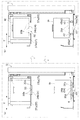
As shown in FIG. 1, the article transport facility 1 includes a
図1及び図2に示すように、第2方向Zに沿って延在する区画体STにより区画された搬送空間が形成されており、搬送空間には、物品WとしてのFOUPを一時的に収納する複数の収納部99が設けられている。第1搬送装置2は、区画体STを貫通する状態で設置され、搬送空間の内外に亘って物品Wを第1方向Xに沿って搬送する。第2搬送装置3は、搬送空間に設置され、搬送空間内において物品Wを第2方向Zに沿って搬送する。
As shown in FIGS. 1 and 2, a transport space partitioned by a partition ST extending in the second direction Z is formed, and the FOUP as the article W is temporarily stored in the transport space. A plurality of
図3〜図7に示すように、第1搬送装置2は、物品Wを下方から支持すると共に第1方向Xに移動自在な搬送支持部2Tを有している。図1及び図2に示すように、第2搬送装置3は、物品Wを支持する移載部34を移載方向に沿って出退自在に備えている。また、第2搬送装置3は、移載部34として、下方移載部34aと当該下方移載部34aよりも上方に配置される上方移載部34bとを備えている。下方移載部34a及び上方移載部34bは同様の構成となっている。そして、下方移載部34a及び上方移載部34bは、物品Wを下方から支持するように構成されている。なお、本明細書において移載方向とは、移載部34が移載対象である物品Wと正対した状態で、移載部34と物品Wとを結ぶ直線の延在方向をいうものとする。
As shown in FIGS. 3-7, the
図4及び図7に示すように、固定荷受台4は、移載方向に対して水平面に沿って直交する幅方向Yの長さが搬送支持部2Tの幅方向Yの長さよりも長く形成された固定通過部41を有している。
As shown in FIGS. 4 and 7, the fixed
図4、図6及び図7に示すように、昇降装置5は、物品Wを下方から支持する昇降荷受台5Tを昇降自在に有している。昇降荷受台5Tは、幅方向Yの長さが上方移載部34bの幅方向Yの長さよりも長く形成された昇降通過部55を有している。また、昇降通過部55の幅方向Yの長さは、下方移載部34aの幅方向Yの長さよりも長く形成されている。また、第1搬送装置2の搬送支持部2Tの幅方向Yの長さは、昇降通過部55の幅方向Yの長さよりも短く形成されている。また、物品Wの幅方向Yの長さは昇降通過部55の幅方向Yの長さよりも長く形成されている。更に、物品Wの幅方向Yの長さは固定通過部41の幅方向Yの長さよりも長く形成されている。
As shown in FIGS. 4, 6, and 7, the
図7に示すように、本実施形態では、昇降荷受台5Tは、固定荷受台4が配置される固定高さHb1よりも上方に位置する昇降基準高さHb2と、当該昇降基準高さHb2よりも上方に位置する昇降待機高さHb3と、の間を昇降自在に構成されている。また、搬送支持部2Tは、昇降基準高さHb2よりも上方で且つ昇降待機高さHb3よりも下方に位置する搬送基準高さHa3と、固定高さHb1よりも下方に位置する授受用高さHa1と、の間で昇降自在に構成されている。
As shown in FIG. 7, in this embodiment, the lifting
図18に示すように、第2搬送装置3は、上方移載部34bと昇降荷受台5Tとが平面視で重複する状態で当該上方移載部34bに昇降通過部55を上下方向に通過させて、昇降荷受台5Tとの間で物品Wを授受するように構成されている。前述したように本実施形態では、上方移載部34bと下方移載部34aとは同様に構成されているため、第2搬送装置3は、下方移載部34aに昇降通過部55を上下方向に通過させることによっても、昇降荷受台5Tとの間で物品Wを授受できるように構成されている。
As shown in FIG. 18, the
また、第2搬送装置3は、下方移載部34aと固定荷受台4とが平面視で重複する状態で当該下方移載部34aに固定通過部41を上下方向に通過させて、固定荷受台4との間で物品Wを授受するように構成されている。更に、第2搬送装置3は、上方移載部34bに固定通過部41を上下方向に通過させることによっても、固定荷受台4との間で物品Wを授受できるように構成されている。
Further, the
本実施形態では、固定高さHb1と昇降待機高さHb3との差が、上方移載部34bと下方移載部34aとの上下方向の設置間隔と等しく設定されている。そのため、本実施形態に係る物品搬送設備1は、固定荷受台4に支持されて固定高さHb1にある物品Wと昇降荷受台5Tに支持されて昇降待機高さHb3にある物品Wとを、下方移載部34aと上方移載部34bとにより同時に移載できる。
In this embodiment, the difference between the fixed height Hb1 and the elevation standby height Hb3 is set equal to the vertical installation interval between the
〔本実施形態の詳細な構成〕
次に、本実施形態の詳細な構成について説明する。
図1及び図2に示すように、第1搬送装置2は、区画体STの内部と外部との間で物品Wを搬送可能に構成されている。第1搬送装置2は、走行フレーム21に沿って第1方向Xを走行可能に構成されている。そして、図3〜図6等に示すように、第1搬送装置2は、物品Wを下方から支持すると共に第1方向Xに移動自在な搬送支持部2Tを有している。走行フレーム21は、長尺の筒状に形成されており、出入口98を通って区画体STを第1方向Xに貫くように設けられている。図1に示すように、走行フレーム21は、床面から立設される複数の脚部材の上端に設けられており、床面から上方に離間した位置に配置されている。例えば、走行フレーム21は、作業者の腰の高さ付近に配置される。そして、走行フレーム21の第1方向Xの両端部のうち、固定荷受台4が配置される端部とは反対側の端部にて、作業者と第1搬送装置2との間で物品Wが授受される。
[Detailed Configuration of the Embodiment]
Next, a detailed configuration of the present embodiment will be described.
As shown in FIG.1 and FIG.2, the
図3に示すように、走行フレーム21の内部は、自走車23が走行可能な走行空間2Sとなっている。自走車23は、自走車23を牽引する第1搬送ベルト2BEと、第1搬送走行モータ2Maにより駆動する駆動プーリ2Paと、第1搬送ベルト2BEの緩みを調整するテンションプーリ2Pbと、第1搬送ベルト2BEを走行フレーム21の長手方向(第1方向X)に案内するガイドプーリ2Pcと、を有している。第1搬送ベルト2BEは、これらの各プーリに一体的に巻き掛けられており、駆動プーリ2Paの駆動により第1方向Xに沿って流動可能に構成されている。自走車23は、水平軸心まわりに回転する従動車輪2Wを、走行空間2Sにおける走行フレーム21の下面に当接する状態で有している。また、自走車23は、走行空間2Sにおいて、第1方向Xに延在する第1搬送ガイドレール24と、第1搬送ガイドレール24の鉛直面に当接すると共に鉛直軸心まわりに回転する第1搬送ガイドローラ25と、を有している。自走車23は以上のように構成されているから、第1搬送ガイドローラ25により第1方向Xに案内されつつ、第1搬送ベルト2BEの作動によりこの第1搬送ベルト2BEに牽引されて、従動車輪2Wの転動により走行空間2Sを走行可能となっている。
As shown in FIG. 3, the interior of the traveling
図3に示すように、自走車23は、第1搬送昇降モータ2Mbにより昇降する第1搬送昇降体26を有している。第1搬送昇降体26の下端部は、第1搬送昇降モータ2Mbと走行空間2Sにて連結している。また、第1搬送昇降体26は、走行フレーム21の上面に形成された走行スリット22から走行フレーム21の上方に突出するように構成されている(図4〜図6も参照)。第1搬送昇降体26の上端部には、第1搬送旋回モータ2Mcにより駆動して第2方向Zに沿う上下軸心まわりに回転する搬送支持部2Tが連結されている。搬送支持部2Tは、昇降自在な第1搬送昇降体26の上端部に連結されていることで、昇降可能な構成となっている。搬送支持部2Tは、主に、搬送基準高さHa3で第1方向Xに移動するように構成されている。また、本実施形態では、搬送支持部2Tは、第1搬送旋回モータ2Mcにより鉛直軸心まわりに回転する第1搬送昇降体26と一体回転するように構成されている。
As shown in FIG. 3, the self-propelled
搬送支持部2Tは、その上面にて物品Wを支持可能に構成されている。搬送支持部2Tの上面には、上方に突出する第1搬送位置決めピン27が設けられている。第1搬送位置決めピン27は、搬送支持部2Tの上面にて合計3つ設けられており、これら3つのピンを繋ぐ線が平面視で三角形となるように配置されている(図5及び図6参照)。第1搬送位置決めピン27は、物品Wの底面に形成された係合溝に嵌まり込むことで、搬送支持部2Tの上面にて支持される物品Wの位置決めを担っている。
The
以上のように構成された自走車23は、搬送支持部2Tにて支持される物品Wを第1搬送昇降体26により昇降させることができ、また、搬送支持部2Tを回転させることで物品Wを旋回させて物品Wを基準姿勢と旋回姿勢とに切り換え可能に構成されている。本実施形態では、搬送支持部2Tに支持された物品Wが自走車23により走行フレーム21を走行中は、物品Wの基準姿勢が維持されるように構成されている。そして、この物品Wが授受位置EPに配置される際には、搬送支持部2Tが旋回して物品Wが旋回姿勢となるように構成されている。本実施形態では、第2搬送装置3による移載に適した姿勢が物品Wの旋回姿勢となる。旋回姿勢とは、物品の移載に適した姿勢であり、移載部が物品を支持し易い姿勢であれば良い。例えば、物品がパレットであり、移載部が係合する係合孔が一側面に形成されている場合には、移載部が当該係合孔に係合可能となるように、当該係合孔と移載部とが対向するような姿勢をいう。なお、自走車23は、物品Wが旋回姿勢を維持したまま走行フレーム21を移動するように構成されていても良い。また、自走車23は、物品Wが常に第2搬送装置3による移載に適した姿勢となるように構成されていても良い。この場合には、物品Wの姿勢切換機能は不要となる。
The self-propelled
図1及び図2に示すように、固定荷受台4は、区画体STの内部における走行フレーム21の端部に設けられている。固定荷受台4は、移載方向に沿う一対の長板が幅方向Yに離間して配置される形態で構成されている。固定荷受台4は、平面視で、一対の長板の間に走行スリット22が配置されるように構成されている。そのため、自走車23の第1搬送昇降体26及び搬送支持部2Tが走行スリット22から上方に突出した状態で、固定荷受台4の一対の長板の間を第1方向Xに通過可能となっている。
As shown in FIG.1 and FIG.2, the fixed
固定荷受台4は、その上面にて物品Wを支持可能に構成されている。図4、図5及び図7に示すように、固定荷受台4に形成される固定通過部41は、固定荷受台4の一対の長板の間に配置されている。授受位置EPにて、搬送支持部2Tが物品Wを下方から支持した状態で搬送基準高さHa3から授受用高さHa1まで移動して固定通過部41を上方から下方に通過すると、物品Wは固定荷受台4に預けられる。このようにして、第1搬送装置2は、物品Wを固定荷受台4に搬送可能に構成されている。固定荷受台4の一対の長板のそれぞれの上面には、上方に突出する固定位置決めピン42が設けられている。固定位置決めピン42は、物品Wの底面に形成された係合溝に嵌り込むことで、固定荷受台4の上面にて支持される物品Wの位置決めを担っている。
The fixed
固定荷受台4のまわりには、授受位置EPにおける物品Wの有無を検出可能な固定在荷センサ4Se1及び固定反射板4Reが設けられている。授受位置EPに物品Wが存在しない状態では、固定在荷センサ4Se1から投光されるレーザが固定反射板4Reに当たって反射し、この反射光を受光することにより授受位置EPに物品Wが存在しない状態が検出される。反対に、授受位置EPに物品Wが存在する状態では、固定在荷センサ4Se1から投光されるレーザは物品Wに遮られることにより当該レーザが固定反射板4Reに到達しないこととなる。すなわち、固定反射板4Reからの反射光が受光されないことにより授受位置EPに物品Wが存在する状態が検出される。
Around the fixed
固定在荷センサ4Se1の他に、固定荷受台4の上面には、スイッチ式の固定着座センサ4Se2が設けられている。固定着座センサ4Se2は、固定荷受台4の一対の長板のそれぞれに設けられている。物品Wが固定荷受台4に支持されているときには、物品Wの底面により固定着座センサ4Se2のスイッチが押されて、固定荷受台4に物品Wが存在する状態が検出される。物品Wが固定荷受台4に支持されていないときには、固定着座センサ4Se2が押されていない状態であるから、固定荷受台4に物品Wが存在しない状態が検出される。このように、固定在荷センサ4Se1及び固定着座センサ4Se2の二重のセンサにより、授受位置EP(固定荷受台4)において物品Wが正しい姿勢で存在しているか否かを検出することができる。
In addition to the fixed load sensor 4Se1, a switch-type fixed seating sensor 4Se2 is provided on the upper surface of the fixed
図1及び図2に示すように、第2搬送装置3は、区画体STの内部に設けられている。第2搬送装置3は、昇降自在に構成されており、また、第1搬送装置2により区画体STの内部に搬入される物品Wを収納部99へ搬送可能に構成されている。更に、第2搬送装置3は、収納部99に収納された物品Wを第1搬送装置2によって搬出させるために、収納部99から授受位置EPへ物品Wを搬送可能に構成されている。
As shown in FIG.1 and FIG.2, the 2nd conveying
第2搬送装置3は、区画体STの内部において第2方向Zに亘って配置される第2搬送昇降ガイド31と、第2搬送昇降モータ(図示省略)により駆動して第2搬送昇降ガイド31に沿って昇降する第2搬送昇降体32と、を有している。図2に示すように、第2搬送昇降ガイド31は、矩形の横断面を有する筒状に形成されている。第2搬送昇降ガイド31の側面のうちの前面3Fには、この前面3Fに当接する第2搬送ガイドローラ33が設けられている。第2搬送ガイドローラ33は、水平軸心まわりに回転して、前面3Fを第2方向Zに転動する。そして、第2搬送ガイドローラ33は、第2搬送昇降体32を第2方向Zに沿って案内する。
The
第2搬送昇降ガイド31には、第2方向Zに沿って配置される第2搬送ベルト3BEが設けられている。第2搬送ベルト3BEは、上下端のそれぞれに配置された回転体(図示省略)に巻き掛けられている。これら回転体のうちの一方が第2搬送昇降モータにより駆動し、この駆動力が第2搬送ベルト3BEを介して他方の回転体に伝わり当該他方の回転体が従動する。これら回転体の作動によって第2搬送ベルト3BEが流動することにより、第2搬送ベルト3BEに連結された第2搬送昇降体32が昇降するように構成されている。
The second
第2搬送昇降体32は、第2搬送昇降ガイド31の前面3F側の外方に突出する形態で設けられている。第2搬送昇降体32は、第2搬送昇降ガイド31の内部における後面3R側に設けられたバランスウェイト3BWと連結している。第2搬送昇降体32は、屈伸自在に構成されたリンク機構3Lを有している。リンク機構3Lの後端部は、第2搬送昇降ガイド31と第2搬送昇降体32とを連結する連結部材に取り付けられている。リンク機構3Lの前端部は、第2搬送旋回モータ(図示省略)によって鉛直軸心まわりに回転する円盤状の旋回台3Tに取り付けられており、この旋回台3Tの上面に物品Wを支持する移載部34が連結されている。そして、旋回台3Tによりリンク機構3Lの一端部に鉛直軸心まわりの回転力を作用させることで、当該リンク機構3Lが屈伸するように構成されている。なお、前述したように、下方移載部34aと上方移載部34bとは同様の構成であるから、以下では、これらをまとめて移載部34として説明することがある。
The 2nd conveyance raising / lowering
移載部34は、リンク機構3Lの屈伸動作により出退するように構成されている。すなわち、リンク機構3Lの屈曲により移載部34は第2搬送昇降ガイド31に近づく方向に移動する(引退動作)。リンク機構3Lの伸長により移載部34は第2搬送昇降ガイド31から遠ざかる方向に移動する(突出動作)。なお、本実施形態では、図2に示すように、平面視で、1つの第2搬送装置3に対して2つの走行フレーム21があり、すなわち、2つの物品授受場所がある場合を例示している。第2搬送装置3は、移載部34を旋回させて当該移載部34を各物品授受場所の物品Wに対して正対させることができるように構成されている。この状態で、第2搬送装置3は、移載部34を移載方向に出退させて物品Wの授受を行う。
The
図1に示すように、下方移載部34aの上面には、上方に突出する下方位置決めピン35a(35)が設けられている。下方位置決めピン35aは、下方移載部34aの上面にて合計3つ設けられており、これら3つのピンを繋ぐ線が平面視で三角形となるように配置されている。同様に、上方移載部34bの上面には、3つの上方位置決めピン35b(35)が、これら3つのピンを繋ぐ線が平面視で三角形となるように配置されている。なお、図2に示すように、第2搬送昇降ガイド31の外側にはケーブルガイド3CBが設けられており、ケーブルガイド3CBの内部で支持される給電線や通信線等により、各アクチュエータに対する電気の供給等が行われている。
As shown in FIG. 1, a
図1及び図2に示すように、昇降装置5は、区画体STの内部における走行フレーム21の端部近傍に設けられている。昇降装置5は、第1搬送装置2により授受位置EPに搬送された走行フレーム21上の物品Wを、当該走行フレーム21から上方に離間した位置に待機させておくことができる。これにより、走行フレーム21上は物品Wのない空き状態となり、第1搬送装置2によって授受位置EPに次の物品Wを搬送することが可能となっている。
As shown in FIG.1 and FIG.2, the raising / lowering
図4に示すように、昇降装置5が備える昇降荷受台5Tは、一対の昇降支持部5Taを有している。一対の昇降支持部5Taは、幅方向Yで互いに離間して配置されている。一対の昇降支持部5Taは、それぞれの上面に立設される門形のフレーム部5Tbにより一体的に形成されている。昇降装置5は、昇降荷受台5Tと幅方向Yで並ぶ位置に、床面に立設される昇降マスト51を有している。昇降マスト51におけるフレーム部5Tbと対向する外側面には、昇降マスト51の延在方向に沿って筒体52が取り付けられている。筒体52の内部には、昇降モータ5Mにより鉛直軸心まわりに回転するボールネジ軸53が設けられている。ボールネジ軸53には、多数のボールを介してナット5Nが取り付けられている。ナット5Nには、連結部材を介して移動ブラケット54が取り付けられている。移動ブラケット54は、昇降モータ5Mによって回転するボールネジ軸53により昇降するナット5Nを介して昇降するように構成されている。移動ブラケット54は、昇降荷受台5Tのフレーム部5Tbと連結している。すなわち、移動ブラケット54の昇降に伴って、この移動ブラケット54とフレーム部5Tbを介して連結する昇降荷受台5Tも昇降するように構成されている。
As shown in FIG. 4, the lifting
図4及び図6に示すように、一対の昇降支持部5Taは、平面視でこれら一対の昇降支持部5Taの間に走行スリット22が配置されるように構成されている。一対の昇降支持部5Taの幅方向Yの間が、昇降通過部55となっている(図7も参照)。前述したように、昇降通過部55の幅方向Yの長さは、搬送支持部2Tの幅方向Yの長さよりも長く形成されている。このため、搬送支持部2Tは昇降荷受台5Tと平面視で重複する状態で、昇降通過部55を上下方向に通過可能となっている。更に、前述したように、物品Wの幅方向Yの長さは昇降通過部55の幅方向Yの長さよりも長く形成されている。このため、搬送支持部2Tが、物品Wを下方から支持した状態で搬送基準高さHa3から授受用高さHa1まで移動して昇降通過部55を上方から下方に通過すると、物品Wは昇降基準高さHb2に位置する昇降荷受台5Tに支持される。このようにして、第1搬送装置2は、物品Wを昇降荷受台5Tに搬送可能に構成されている。
As shown in FIG.4 and FIG.6, a pair of raising / lowering support part 5Ta is comprised so that the driving | running | working slit 22 may be arrange | positioned between these pair of raising / lowering support part 5Ta by planar view. Between the width direction Y of a pair of raising / lowering support part 5Ta is the raising / lowering passage part 55 (refer also FIG. 7). As described above, the length in the width direction Y of the elevating / lowering
図4及び図6に示すように、一対の昇降支持部5Taのそれぞれの上面には、上方に突出する昇降位置決めピン56が設けられている。昇降位置決めピン56は、物品Wの底面に形成された係合溝に嵌り込むことで、昇降荷受台5Tの上面にて支持される物品Wの位置決めを担っている。
As shown in FIG.4 and FIG.6, the raising / lowering
一対の昇降支持部5Taのうちの一方には、昇降荷受台5Tにおける物品Wの有無を検出可能な昇降在荷センサ5Se1設けられている。一対の昇降支持部5Taのうちの他方には、昇降在荷センサ5Se1から投光されるレーザを反射する昇降反射板5Reが設けられている。昇降荷受台5Tに物品Wが存在しない状態では、昇降在荷センサ5Se1から投光されるレーザが昇降反射板5Reに当たって反射し、この反射光を受光することにより昇降荷受台5Tに物品Wが存在しない状態が検出される。反対に、昇降荷受台5Tに物品Wが存在する状態では、昇降在荷センサ5Se1から投光されるレーザは物品Wに遮られることにより昇降反射板5Reに到達しないこととなる。すなわち、昇降反射板5Reからの反射光が受光されないことにより授受位置EPに物品Wが存在する状態が検出される。
One of the pair of lifting support portions 5Ta is provided with a lifting / lowering load sensor 5Se1 capable of detecting the presence / absence of the article W in the lifting
昇降在荷センサ5Se1の他に、昇降荷受台5Tの上面には、スイッチ式の昇降着座センサ5Se2が設けられている。昇降着座センサ5Se2は、一対の昇降支持部5Taのそれぞれに設けられている。物品Wが昇降荷受台5Tに支持されているときには、物品Wの底面により昇降着座センサ5Se2のスイッチが押されて、昇降荷受台5Tに物品Wが存在する状態が検出される。物品Wが昇降荷受台5Tに支持されていないときには、昇降着座センサ5Se2が押されていない状態であるから、昇降荷受台5Tに物品Wが存在しない状態が検出される。このように、昇降在荷センサ5Se1及び昇降着座センサ5Se2の二重のセンサにより、昇降荷受台5Tにおいて物品Wが正しい姿勢で存在しているか否かを検出することができる。
In addition to the lifting / lowering load sensor 5Se1, a switch-type lifting / lowering seating sensor 5Se2 is provided on the upper surface of the lifting / lowering
〔制御構成〕
図8に示すように、制御部6は、第2搬送装置3の動作を制御する第1制御装置C1と、第1搬送装置2及び昇降装置5の動作を制御する第2制御装置C2と、これらを総括的に制御する上位制御装置Cと、を備えている。
[Control configuration]
As shown in FIG. 8, the
第1制御装置C1は、上方移載部34b及び下方移載部34aの動作を制御することにより、第2搬送装置3に物品Wの授受を行わせるように構成されている。第2制御装置C2は、固定在荷センサ4Se1、固定着座センサ4Se2、昇降在荷センサ5Se1及び昇降着座センサ5Se2の各種センサにより検出された情報に基づいて第1搬送装置2及び昇降装置5の動作を制御するように構成されている。すなわち、第2制御装置C2は、第1搬送走行モータ2Maを制御して、自走車23の第1方向Xにおける走行及び走行停止を制御するように構成されている。また、第2制御装置C2は、第1搬送昇降モータ2Mbを制御して、搬送支持部2Tの昇降及び昇降停止を制御するように構成されている。また、第2制御装置C2は、第1搬送旋回モータ2Mcを制御して、搬送支持部2Tの回転を制御するように構成されている。これにより物品Wの基準姿勢と旋回姿勢とが切換可能となっている。
The 1st control apparatus C1 is comprised so that the 2nd conveying
制御部6は、昇降荷受台5T又は固定荷受台4への物品Wの搬送を第1搬送装置2に行わせる第1搬送処理を実行可能に構成されている。本実施形態では、第1搬送処理は、第1昇降モードと第2昇降モードとを備えている。すなわち、制御部6は、搬送支持部2Tを、搬送基準高さHa3と授受用高さHa1との間で昇降させる第1昇降モードと、固定高さHb1よりも上方で且つ昇降基準高さHb2よりも下方に位置する搬送基準第2高さHa2と授受用高さHa1との間で昇降させる第2昇降モードと、を実行可能に構成されている。
The
図9は、第1昇降モードでの第1搬送処理が実行される際のフローチャートを示している。第1昇降モードは、第2昇降モードに比べて第1搬送装置2の搬送支持部2Tの昇降範囲が広くなるように構成されたモードである。図示しないが、走行フレーム21の第1方向Xにおける授受位置EPの反対側は、作業者が物品Wを第1搬送装置2の搬送支持部2Tに載せる投入位置となっている。作業者が投入位置にて搬送支持部2Tに物品Wを載せた後、第1搬送処理のうちの第1昇降モードが実行される。図9に示すように、第1昇降モードでは、まず、搬送支持部2Tが搬送基準高さHa3にあるか否かが判断される(ステップ#11)。搬送支持部2Tが搬送基準高さHa3にあると判断された場合には(ステップ#11:Yes)、授受位置EPに向かって自走車23の走行が開始される(ステップ#12)。搬送支持部2Tが搬送基準高さHa3にないと判断された場合には(ステップ#11:No)、搬送支持部2Tを搬送基準高さHa3に位置させる高さ調整が行われた上で(ステップ#13)、自走車23の走行が開始される(ステップ#12)。
FIG. 9 shows a flowchart when the first transport process is executed in the first lifting / lowering mode. The first lifting / lowering mode is a mode configured such that the lifting / lowering range of the
次に、自走車23が授受位置EPに相当する授受用停止位置に到達したか否かが判断される(ステップ#14)。自走車23が授受用停止位置に到達したと判断された場合には(ステップ#14:Yes)、自走車23の走行が停止される(ステップ#15)。自走車23が授受用停止位置に到達していないと判断された場合には(ステップ#14:No)、ステップ#14が繰り返される。自走車23の走行を停止させた後は、搬送支持部2Tの下降が開始される(ステップ#16)。次に、搬送支持部2Tが授受用高さHa1に到達したか否かが判断される(ステップ#17)。搬送支持部2Tが授受用高さHa1に到達したと判断された場合には(ステップ#17:Yes)、搬送支持部2Tの下降が停止される(ステップ#18)。搬送支持部2Tが授受用高さHa1に到達していないと判断された場合には(ステップ#17:No)、ステップ#17が繰り返される。
Next, it is determined whether or not the self-propelled
授受用停止位置にて搬送支持部2Tの下降が停止された後は、投入位置に向かって自走車23の走行が開始される(ステップ#19)。次に、自走車23が投入位置に相当する投入用停止位置に到達した否かが判断される(ステップ#20)。自走車23が投入用停止位置に到達したと判断された場合には(ステップ#20:Yes)、自走車23の走行が停止される(ステップ#21)。自走車23が投入用停止位置に到達していないと判断された場合には(ステップ#20:No)、ステップ#20が繰り返される。自走車23の走行が停止された後は、投入用停止位置にて搬送支持部2Tの上昇が開始される(ステップ#22)。次に、搬送支持部2Tが搬送基準高さHa3に到達したか否かが判断される(ステップ#23)。搬送支持部2Tが搬送基準高さHa3に到達したと判断された場合には(ステップ#23:Yes)、搬送支持部2Tの上昇が停止される(ステップ#24)。搬送支持部2Tが搬送基準高さHa3に到達していないと判断された場合には(ステップ#23:No)、ステップ#23が繰り返される。以上の工程で、第1昇降モードが実行される。
After the lowering of the
次に、第2昇降モードでの第1搬送処理について説明する。図10は、第2昇降モードでの第1搬送処理が実行される際のフローチャートを示している。第2昇降モードは、第1昇降モードに比べて第1搬送装置2の搬送支持部2Tの昇降範囲が狭くなるように構成されたモードである。また、第2昇降モードは、少なくとも、昇降荷受台5Tが昇降待機高さHb3にある状態で固定荷受台4に物品Wを搬送するモードである。作業者が投入位置にて搬送支持部2Tに物品Wを載せた後、第1搬送処理のうちの第2昇降モードが実行される。図10に示すように、第2昇降モードでは、まず、搬送支持部2Tが搬送基準第2高さHa2にあるか否かが判断される(ステップ#31)。搬送支持部2Tが搬送基準第2高さH2にあると判断された場合には(ステップ#31:Yes)、授受位置EPに向かって自走車23の走行が開始される(ステップ#32)。搬送支持部2Tが搬送基準第2高さHa2にないと判断された場合には(ステップ#31:No)、搬送支持部2Tを搬送基準第2高さHa2に位置させる高さ調整が行われた上で(ステップ#33)、自走車23の走行が開始される(ステップ#32)。
Next, the 1st conveyance process in 2nd raising / lowering mode is demonstrated. FIG. 10 shows a flowchart when the first transport process in the second lift mode is executed. The second lifting / lowering mode is a mode configured such that the lifting / lowering range of the
次に、自走車23が授受用停止位置に到達したか否かが判断される(ステップ#34)。自走車23が授受用停止位置に到達したと判断された場合には(ステップ#34:Yes)、自走車23の走行が停止される(ステップ#35)。自走車23が授受用停止位置に到達していないと判断された場合には(ステップ#34:No)、ステップ#34が繰り返される。自走車23の走行を停止させた後は、搬送支持部2Tの下降が開始される(ステップ#36)。次に、搬送支持部2Tが授受用高さHa1に到達したか否かが判断される(ステップ#37)。搬送支持部2Tが授受用高さHa1に到達したと判断された場合には(ステップ#37:Yes)、搬送支持部2Tの下降が停止される(ステップ#38)。搬送支持部2Tが授受用高さHa1に到達していないと判断された場合には(ステップ#37:No)、ステップ#37が繰り返される。
Next, it is determined whether or not the self-propelled
授受用停止位置にて搬送支持部2Tの下降が停止された後は、投入位置に向かって自走車23の走行が開始される(ステップ#39)。次に、自走車23が投入用停止位置に到達したか否かが判断される(ステップ#40)。自走車23が投入用停止位置に到達したと判断された場合には(ステップ#40:Yes)、自走車23の走行が停止される(ステップ#41)。自走車23が投入用停止位置に到達していないと判断された場合には(ステップ#40:No)、ステップ#40が繰り返される。自走車23の走行が停止された後は、投入用停止位置にて搬送支持部2Tの上昇が開始される(ステップ#42)。次に、搬送支持部2Tが搬送基準第2高さHa2に到達したか否かが判断される(ステップ#43)。搬送支持部2Tが搬送基準第2高さHa2に到達したと判断された場合には(ステップ#43:Yes)、搬送支持部2Tの上昇が停止される(ステップ#44)。搬送支持部2Tが搬送基準第2高さHa2に到達していないと判断された場合には(ステップ#43:No)、ステップ#43が繰り返される。以上の工程で、第2昇降モードが実行される。
After the lowering of the
〔動作〕
次に、図11及び図12のフローチャート並びに図13〜図17を参照して物品Wを搬送する際の物品搬送設備1の動作について説明する。なお、図11は、昇降荷受台5Tに物品Wを搬送する際の工程を示すフローチャートである。図12は、固定荷受台4に物品Wを搬送する際の工程を示すフローチャートである。
[Operation]
Next, the operation of the article transport facility 1 when transporting the article W will be described with reference to the flowcharts of FIGS. 11 and 12 and FIGS. 13 to 17. In addition, FIG. 11 is a flowchart which shows the process at the time of conveying the articles | goods W to the raising / lowering
昇降荷受台5Tに物品Wを搬送する際の物品搬送設備1の動作について説明する。まず、図11に示すように、物品Wが搬送される対象の昇降荷受台5Tに物品Wが載置されているか否かが判断される(ステップ#51)。この判断は、昇降在荷センサ5Se1及び昇降着座センサ5Se2の作動の有無に基づいて行われる。これらのセンサがオン状態の場合には昇降荷受台5Tに物品Wが載置されている状態であると判断され、これらのセンサがオフ状態の場合には昇降荷受台5Tに物品Wが載置されていない状態であると判断される。昇降荷受台5Tに物品Wが載置されていない状態であると判断された場合には(ステップ#51:Yes)、昇降荷受台5Tを昇降基準高さHb2に配置させるべく、昇降荷受台5Tの下降が開始される(ステップ#52)。昇降荷受台5Tに物品Wが載置されていると判断された場合には(ステップ#51:No)、異常通知がされて(ステップ#53)、昇降荷受台5Tへの物品Wの搬送が中止される。昇降荷受台5Tの下降が開始された後は、昇降荷受台5Tが昇降基準高さHb2に到達したか否かが判断される(ステップ#54)。昇降荷受台5Tが昇降基準高さHb2に到達していないと判断された場合には(ステップ#54:No)、ステップ#54が繰り返される。昇降荷受台5Tが昇降基準高さHb2に到達したと判断された場合には(ステップ#54:Yes)、昇降荷受台5Tの下降が停止される(ステップ#55)。
The operation of the article transport facility 1 when transporting the article W to the lifting / lowering
昇降荷受台5Tの下降を停止した後は、前述の第1昇降モードでの第1搬送処理が実行される(ステップ#56)。すなわち、図13に示すように、搬送支持部2Tによって搬送基準高さHa3にて物品Wを支持すると共に自走車23を授受用停止位置で停止させることで、物品Wと昇降荷受台5Tとが平面視で重複する状態で物品Wを昇降荷受台5Tの上方に配置させる。そして、図14に示すように、搬送支持部2Tを授受用高さHa1に下降させる過程で、物品Wが昇降荷受台5Tに預けられることにより当該物品Wが昇降荷受台5Tに載置された状態となる。物品Wが昇降荷受台5Tに載置された状態は、昇降着座センサ5Se2が物品Wの底面により押されたこと、すなわち、昇降着座センサ5Se2がオン状態となったことにより確認できる。図11に示すように、第1昇降モードの実行後は(ステップ#56)、昇降荷受台5Tの上昇が開始される(ステップ#57)(図15も参照)。次に、昇降荷受台5Tが昇降待機高さHb3に到達したか否かが判断される(ステップ#58)。昇降荷受台5Tが昇降待機高さHb3に到達していないと判断された場合には(ステップ#58:No)、ステップ#58が繰り返される。昇降荷受台5Tが昇降待機高さHb3に到達したと判断された場合には(ステップ#58:Yes)、昇降荷受台5Tの上昇が停止される(ステップ#59)。以上により、昇降荷受台5Tへの物品Wの搬送が完了する(図15参照)。
After stopping the descending of the
次に、固定荷受台4に物品Wを搬送する際の物品搬送設備1の動作について説明する。まず、図12に示すように、固定荷受台4に物品Wが載置されているか否かが判断される(ステップ#61)。この判断は、固定在荷センサ4Se1及び固定着座センサ4Se2の作動の有無に基づいて行われる。これらのセンサがオン状態の場合には固定荷受台4に物品Wが載置されている状態であると判断され、これらのセンサがオフ状態の場合には固定荷受台4に物品Wが載置されていない状態であると判断される。固定荷受台4に物品Wが載置されていないと判断された場合には(ステップ#61:Yes)、固定荷受台4に物品Wが載置される上下方向のスペースを確保するため、昇降荷受台5Tを昇降待機高さHb3に配置させるべく、当該昇降荷受台5Tの上昇が開始される(ステップ#62)。固定荷受台4に物品Wが載置されていると判断された場合には(ステップ#61:No)、異常通知がされて(#63)、第2昇降モードでの第1搬送処理が中止される。昇降荷受台5Tの上昇が開始された後は、昇降荷受台5Tが昇降待機高さHb3に到達したか否かが判断される(ステップ#64)。昇降荷受台5Tが昇降待機高さHb3に到達していないと判断された場合には(ステップ#64:No)、ステップ#64が繰り返される。昇降荷受台5Tが昇降待機高さHb3に到達したと判断された場合には(ステップ#64:Yes)、昇降荷受台5Tの上昇が停止される(ステップ#65)。昇降荷受台5Tの上昇が停止された後は、前述の第1昇降モードが実行される(ステップ#66)。すなわち、図16に示すように、搬送支持部2Tによって搬送基準高さHa3にて物品Wを支持すると共に自走車23を授受用停止位置で停止させることで、物品Wと固定荷受台4とが平面視で重複する状態で物品Wを固定荷受台4の上方に配置させる。そして、図17に示すように、搬送支持部2Tを授受用高さHa1に下降させる過程で、物品Wが固定荷受台4に預けられることにより当該物品Wが固定荷受台4に載置された状態となる。物品Wが固定荷受台4に載置された状態は、固定着座センサ4Se2が物品Wの底面により押されたこと、すなわち、固定着座センサ4Se2がオン状態となったことにより確認できる。以上により、固定荷受台4への物品Wの搬送が完了する(図17参照)。
Next, the operation of the article conveying facility 1 when conveying the article W to the fixed load receiving table 4 will be described. First, as shown in FIG. 12, it is determined whether or not the article W is placed on the fixed load receiving stand 4 (step # 61). This determination is made based on whether or not the fixed load sensor 4Se1 and the fixed seating sensor 4Se2 are activated. When these sensors are in the on state, it is determined that the article W is placed on the fixed load receiving table 4. When these sensors are in the off state, the article W is placed on the fixed load receiving table 4. It is determined that this is not done. When it is determined that the article W is not placed on the fixed load receiving platform 4 (step # 61: Yes), the vertical movement is performed in order to secure a vertical space in which the article W is placed on the fixed
図18に示すように、固定荷受台4及び昇降荷受台5Tのそれぞれに載置された物品Wは、第2搬送装置3により移載される。すなわち、下方移載部34aを移載方向に突出させることで、下方移載部34aと物品Wとが平面視で重複した状態で下方移載部34aを物品Wの下方に配置させる。これと同様に、上方移載部34bを移載方向に突出させることで、上方移載部34bと物品Wとが平面視で重複した状態で上方移載部34bを物品Wの下方に配置させる。そして、下方移載部34aを上方に移動させて固定通過部41を通過させると共に下方移載部34aにより固定荷受台4に載置された物品Wを下方から支持する。このとき、下方移載部34aの上面に形成された下方位置決めピン35aが物品Wの底面に形成された係合溝に嵌まり込んで、物品Wが位置決めされる。これと同様に、上方移載部34bを上方に移動させて昇降通過部55を通過させると共に上方移載部34bにより昇降荷受台5Tに載置された物品Wを下方から支持する。このとき、上方移載部34bの上面に形成された上方位置決めピン35bが物品Wの底面に形成された係合溝に嵌まり込んで、物品Wが位置決めされる。ここで、前述したように、本実施形態では、固定高さHb1と昇降待機高さHb3との差が、上方移載部34bと下方移載部34aとの上下方向の設置間隔と等しく設定されている。そのため、本実施形態では、固定荷受台4及び昇降荷受台5Tのそれぞれに載置された物品Wを下方移載部34a及び上方移載部34bにより同時に受け取ることができる(図18(b)参照)。また、下方移載部34a及び上方移載部34bのそれぞれが物品Wを支持した状態で、これら下方移載部34a及び上方移載部34bのそれぞれに固定通過部41及び昇降通過部55のそれぞれを上方から下方に通過させることで、固定荷受台4及び昇降荷受台5Tのそれぞれに物品Wを預けることができる(図18(a)参照)。なお、物品Wの授受は、下方移載部34a及び上方移載部34bの双方で同時に行わなくても良く、例えば、図19に示すように、上方移載部34bのみによって昇降荷受台5Tとの間で物品Wを授受するようにしても良い。もちろん、図示しないが、下方移載部34aのみによって固定荷受台4との間で物品Wを授受するようにしても良い。
As shown in FIG. 18, the article W placed on each of the fixed load receiving table 4 and the lifted load receiving table 5 </ b> T is transferred by the
以上は、固定荷受台4及び昇降荷受台5Tに物品Wを搬送する場合の物品搬送設備1の動作について説明した。以上説明したように、本実施形態では、制御部6は、昇降荷受台5Tが昇降基準高さHb2及び昇降待機高さHb3にあるいずれの場合にも、搬送支持部2Tを搬送基準高さHa3と授受用高さHa1との間で昇降させるべく第1搬送装置2を制御するように構成されている。すなわち、本実施形態では、昇降荷受台5Tが昇降基準高さHb2及び昇降待機高さHb3にあるいずれの場合であっても、制御部6は、第1搬送処理の第1昇降モードを実行することにより固定荷受台4又は昇降荷受台5Tに物品Wを搬送するように構成されている。前述したように、昇降荷受台5Tへの物品Wの搬送と固定荷受台4への物品Wの搬送とを連続して行う場合には、いずれの場所への搬送も第1昇降モードで行うことにより、制御の変更(第2昇降モードへの変更)が不要であり、簡易な制御構成にできる。
The operation of the article transport facility 1 when transporting the article W to the fixed
一方で、第2昇降モードにおける搬送支持部2Tを昇降させる範囲は、第1昇降モードを用いる場合よりも狭くなる。そのため、これら2つのモードを比べた場合に、第2昇降モードを用いて物品Wを搬送する場合の方が、搬送時間を短縮できる。例えば、第2搬送装置3の下方移載部34a及び上方移載部34bのうちいずれかが故障して1つの移載部34にて運用する場合には、昇降装置5の作動により昇降荷受台5Tを昇降待機高さHb3に退避させて、固定荷受台4のみを用いて物品Wの授受を行うことになる。この場合には、昇降基準高さHb2を下限高さとする昇降荷受台5Tが昇降待機高さHb3に退避しているので、昇降待機高さHb3よりも下方に位置する搬送基準高さHa3を昇降範囲の上限高さとする第1昇降モードを実行可能である。もちろん、第1昇降モードよりも昇降範囲の狭い第2昇降モードも実行可能である。この場合、本実施形態では、第2昇降モードを選択することにより物品Wの搬送時間の短縮を図っている。
On the other hand, the range in which the
本実施形態では、制御部6は、第1昇降モードと第2昇降モードとの間でモードの切り換えを行うモード切換処理を実行可能に構成されている。図20は、モード切換処理のフローチャートを示している。まず、第2昇降モード切換指令の有無が判断される(ステップ#71)。ここで、第2昇降モード切換指令は、第2搬送装置3に故障などの不具合があった場合であって、物品Wの移載を下方移載部34a及び上方移載部34bのいずれかで行う場合に、第2昇降モードを実行するように上位制御装置Cからなされる指令である。第2昇降モード切換指令がされていないと判断された場合には(ステップ#71:No)、ステップ#71が繰り返される。第2昇降モード切換指令がされていると判断された場合には(ステップ#71:Yes)、昇降荷受台5Tに物品Wが載置されているか否かが判断される(ステップ#72)。昇降荷受台5Tに物品Wが載置されていると判断された場合には(ステップ#72:No)、ステップ#72が繰り返される。なお、この場合には、運用状態の移載部34により昇降荷受台5Tに載置されている物品Wを移載して、昇降荷受台5Tを空き状態とするようにしても良い。また、搬送支持部2Tに物品Wを支持させた状態で当該物品Wを投入位置まで搬送させることで昇降荷受台5Tを空き状態とするようにしても良い。いずれにしても、昇降荷受台5Tから物品Wを除去する処理をして、昇降荷受台5Tを空き状態、すなわち、昇降荷受台5Tに物品Wが載置されていない状態とすれば良い。そして、昇降荷受台5Tに物品Wが載置されていないと判断された場合には(ステップ#72:Yes)、昇降荷受台5Tが昇降待機高さHb3にあるか否かが判断される(ステップ#73)。昇降荷受台5Tが昇降待機高さHb3にあると判断された場合には(ステップ#73:Yes)、搬送支持部2Tの上限高さの設定を、第1昇降モード時の搬送支持部2Tの上限高さである搬送基準高さHa3から、第2昇降モード時の搬送支持部2Tの上限高さである搬送基準第2高さHa2に変更する(ステップ#74)。そして、昇降荷受台5Tが昇降待機高さHb3にないと判断された場合には(ステップ#73:No)、昇降荷受台5Tを昇降待機高さHb3に位置させる高さ調整を行った上(ステップ#75)、搬送支持部2Tの上限高さを搬送基準高さHa3から搬送基準第2高さHa2に変更する(ステップ#74)。
In this embodiment, the
制御部6によるモード切換処理の実行後は、固定荷受台4へ物品Wを搬送する処理を行う。具体的には、図12に示すステップ#9の工程を第2昇降モードによって実行することで、物品Wが固定荷受台4へ搬送される。図21に示すように、昇降荷受台5Tを昇降待機高さHb3に配置させた状態で、搬送支持部2Tにより搬送基準第2高さHa2にて物品Wを支持し、物品Wと搬送支持部2Tとが平面視で重複する位置に搬送支持部2Tを配置させる。そして、搬送支持部2Tを授受用高さHa1に下降させる過程で、物品Wが固定荷受台4に預けられることにより当該物品Wが固定荷受台4に載置された状態となる。このように、第2昇降モードにて物品Wを固定荷受台4に搬送する場合には、搬送支持部2Tの昇降範囲を狭くすることができ、その結果、物品Wの搬送時間を短縮できる。なお、以上では、第2搬送装置3の故障により下方移載部34a及び上方移載部34bのうちいずれかで運用する場合に第2昇降モードを用いて物品Wを搬送する場合について説明した。しかし、第2搬送装置3が正常状態で下方移載部34a及び上方移載部34bの双方で運用可能な場合であっても、固定荷受台4への物品Wの搬送時には、第2昇降モードを用いても差し支えない。
After execution of the mode switching process by the
〔その他の実施形態〕
(1)上記の実施形態では、下方移載部34a及び上方移載部34bが、物品Wの底面を下方から支持するように構成された例について説明した。しかし、本発明は、このような構成に限定されない。すなわち、下方移載部及び上方移載部は、物品を支持可能に構成されていれば良く、例えば、物品にフランジ部や係合孔などが形成されている場合にこれらを下方から支持するように構成されていても良い。更に、チャック機構を用いて物品を把持するように構成されていても良い。
[Other Embodiments]
(1) In the above-described embodiment, the example in which the
(2)上記の実施形態では、下方移載部34a及び上方移載部34bが同様の構成である例について説明した。しかし、本発明はこのような構成に限定されない。例えば、下方移載部及び上方移載部のうちの一方がチャック機構等により物品を把持するように構成され、他方が物品を下方から支持するように構成されていても良い。
(2) In the above embodiment, the example in which the
(3)上記の実施形態では、昇降装置5が所謂ボールネジを用いて昇降荷受台5Tを昇降させるように構成された例について説明した。しかし、本発明は、このような構成に限定されない。すなわち、昇降荷受台を昇降させるために、電動シリンダや回動チェーン等の公知の手段を用いることもできる。
(3) In the above-described embodiment, the example in which the
(4)上記の実施形態では、物品WとしてFOUPを例にして説明した。しかし、本発明に係る物品搬送設備は、大小、形状、様々な物品の搬送に適用することができる。ただし、移載部が物品の底面を下方から支持するように構成される場合には、物品の幅方向における長さは、少なくとも、移載部の幅方向における長さよりも長いものが適用対象となる。このようなものが適用対象であると、移載部が物品を支持した状態で固定荷受台の固定通過部又は昇降荷受台の昇降通過部を上方から下方に通過する過程で、物品を固定荷受台又は昇降荷受台に預けることができる。 (4) In the above embodiment, the article W has been described using the FOUP as an example. However, the article conveyance facility according to the present invention can be applied to conveyance of various articles of large, small, and shape. However, when the transfer unit is configured to support the bottom surface of the article from below, the length in the width direction of the article is at least longer than the length in the width direction of the transfer unit. Become. When such a thing is an object of application, the article is fixedly received in the process of passing from the upper part to the lower part of the fixed passing part of the fixed load receiving base or the rising and lowering passing part of the lifting load receiving base with the transfer part supporting the article. It can be deposited on a table or a lift receiving platform.
(5)上記の実施形態では、走行フレーム21の第1方向Xの両端部のうち、固定荷受台4が配置される端部とは反対側の端部にて、第1搬送装置2と物品Wの授受を行うのは作業者である例について説明した。しかし、第1搬送装置と物品の授受を行うのは作業者に限られず、無人搬送車、天井搬送車又は台車や有人フォークリフトなどであっても良い。
(5) In the above-described embodiment, the
(6)これらの各実施形態は、単なる例示に過ぎない。また、これらの各実施形態は、本発明の趣旨を逸脱しない範囲で相互に組み合わせることができる。 (6) Each of these embodiments is merely illustrative. These embodiments can be combined with each other without departing from the spirit of the present invention.
1 :物品搬送設備
2 :第1搬送装置
2T :搬送支持部
3 :第2搬送装置
4 :固定荷受台
5 :昇降装置
5T :昇降荷受台
6 :制御部
34 :移載部
34a :下方移載部
34b :上方移載部
41 :固定通過部
55 :昇降通過部
56 :昇降位置決めピン
EP :授受位置
H2 :搬送基準第2高さ
Ha1 :授受用高さ
Ha2 :搬送基準第2高さ
Ha3 :搬送基準高さ
Hb1 :固定高さ
Hb2 :昇降基準高さ
Hb3 :昇降待機高さ
W :物品
X :第1方向
Y :幅方向
Z :第2方向
DESCRIPTION OF SYMBOLS 1: Article conveyance equipment 2:
Claims (5)
前記授受位置と平面視で重複する領域で物品を昇降させる昇降装置を更に備え、
前記第2搬送装置は、物品を支持する移載部を移載方向に沿って出退自在に備え、
前記第2搬送装置は、前記移載部として、下方移載部と当該下方移載部よりも上方に配置される上方移載部とを備え、
前記昇降装置は、物品を下方から支持する昇降荷受台を昇降自在に有し、
前記昇降荷受台は、前記固定荷受台が配置される固定高さよりも上方に位置する昇降基準高さと、当該昇降基準高さよりも上方に位置する昇降待機高さと、の間を昇降自在に構成され、
前記固定高さと前記昇降待機高さとの差が、前記上方移載部と前記下方移載部との上下方向の設置間隔と等しく設定されている物品搬送設備。 A first transport device that transports an article in a first direction along a horizontal plane, a second transport device that transports an article in a second direction along the vertical direction, and the first transport device and the second transport device are An article conveying facility comprising a fixed load receiving stand disposed at a delivery position for delivering,
An elevating device that elevates and lowers the article in a region overlapping with the delivery position in plan view;
The second transport device includes a transfer unit that supports an article so that the transfer unit can freely move in and out along the transfer direction.
The second transport device includes, as the transfer unit, a lower transfer unit and an upper transfer unit disposed above the lower transfer unit,
The elevating device has an elevating load receiving table that supports the article from below, and can be raised and lowered,
The lifting load receiving platform is configured to freely move up and down between a lifting reference height positioned above a fixed height at which the fixed load receiving table is disposed and a lifting standby height positioned higher than the lifting reference height. ,
The article conveyance facility, wherein a difference between the fixed height and the elevation standby height is set equal to a vertical installation interval between the upper transfer unit and the lower transfer unit.
前記昇降荷受台は、前記移載方向に対して水平面に沿って直交する幅方向の長さが前記上方移載部の前記幅方向の長さよりも長く形成された昇降通過部を有し、
物品の前記幅方向の長さは前記昇降通過部の前記幅方向の長さよりも長く形成され、
前記第2搬送装置は、前記上方移載部と前記昇降荷受台とが平面視で重複する状態で当該上方移載部に前記昇降通過部を上下方向に通過させて、前記昇降荷受台との間で物品を授受するように構成されている請求項1に記載の物品搬送設備。 The upper transfer part is configured to support an article from below,
The lifting load receiving platform has a lifting and lowering passage portion formed so that the length in the width direction orthogonal to the transfer direction along the horizontal plane is longer than the length in the width direction of the upper transfer portion,
The length in the width direction of the article is formed longer than the length in the width direction of the elevating passage part,
The second transfer device allows the upper transfer portion and the lift load receiving table to overlap each other in a plan view so that the upper transfer portion passes the lift transfer portion in the vertical direction. The article conveying facility according to claim 1, wherein the article conveying facility is configured to exchange articles between the two.
前記搬送支持部は、前記昇降基準高さよりも上方で且つ前記昇降待機高さよりも下方に位置する搬送基準高さと、前記固定高さよりも下方に位置する授受用高さと、の間で昇降自在に構成され、
前記固定荷受台は、前記幅方向の長さが前記搬送支持部の前記幅方向の長さよりも長く形成された固定通過部を有し、
前記搬送支持部の前記幅方向の長さは、前記昇降通過部の前記幅方向の長さよりも短く形成され、
物品の前記幅方向の長さは前記固定通過部の前記幅方向の長さよりも長く形成され、
前記第2搬送装置は、前記下方移載部と前記固定荷受台とが平面視で重複する状態で当該下方移載部に前記固定通過部を上下方向に通過させて、前記固定荷受台との間で物品を授受するように構成されている請求項2に記載の物品搬送設備。 The first transport device has a transport support unit that supports an article from below and is movable in the first direction,
The transport support portion is movable up and down between a transport reference height located above the lift reference height and below the lift standby height, and a transfer height located below the fixed height. Configured,
The fixed load receiving platform has a fixed passage portion in which the length in the width direction is longer than the length in the width direction of the transport support portion,
The length in the width direction of the transport support portion is formed shorter than the length in the width direction of the lift passage portion,
The length in the width direction of the article is formed longer than the length in the width direction of the fixed passage portion,
The second transfer device allows the lower transfer portion and the fixed load receiving table to overlap with each other in a plan view so that the lower transfer portion passes the fixed passing portion in the vertical direction, and The article transport facility according to claim 2, which is configured to receive and receive articles between the two.
前記制御部は、前記昇降荷受台が前記昇降基準高さ及び前記昇降待機高さにあるいずれの場合にも、前記搬送支持部を前記搬送基準高さと前記授受用高さとの間で昇降させるべく前記第1搬送装置を制御するように構成されている請求項3に記載の物品搬送設備。 A control unit for controlling the operation of the first transfer device;
The control unit is configured to raise and lower the transport support unit between the transport reference height and the transfer height in any case where the lift platform is at the lift reference height and the lift standby height. The article conveyance facility according to claim 3, wherein the article conveyance facility is configured to control the first conveyance device.
Priority Applications (2)
| Application Number | Priority Date | Filing Date | Title |
|---|---|---|---|
| JP2016176983A JP6593287B2 (en) | 2016-09-09 | 2016-09-09 | Goods transport equipment |
| KR1020170090988A KR102346976B1 (en) | 2016-09-09 | 2017-07-18 | Article transport facility |
Applications Claiming Priority (1)
| Application Number | Priority Date | Filing Date | Title |
|---|---|---|---|
| JP2016176983A JP6593287B2 (en) | 2016-09-09 | 2016-09-09 | Goods transport equipment |
Publications (2)
| Publication Number | Publication Date |
|---|---|
| JP2018039660A JP2018039660A (en) | 2018-03-15 |
| JP6593287B2 true JP6593287B2 (en) | 2019-10-23 |
Family
ID=61625214
Family Applications (1)
| Application Number | Title | Priority Date | Filing Date |
|---|---|---|---|
| JP2016176983A Active JP6593287B2 (en) | 2016-09-09 | 2016-09-09 | Goods transport equipment |
Country Status (2)
| Country | Link |
|---|---|
| JP (1) | JP6593287B2 (en) |
| KR (1) | KR102346976B1 (en) |
Families Citing this family (5)
| Publication number | Priority date | Publication date | Assignee | Title |
|---|---|---|---|---|
| JP6825604B2 (en) * | 2018-04-27 | 2021-02-03 | 株式会社ダイフク | Goods transport equipment and goods transport equipment |
| JP6835031B2 (en) | 2018-04-27 | 2021-02-24 | 株式会社ダイフク | Goods transport equipment |
| CN110540064A (en) * | 2018-07-17 | 2019-12-06 | 蓝思智能机器人(长沙)有限公司 | Assembly line production system, conveying mechanism thereof and conveying method |
| JP7111003B2 (en) * | 2019-01-23 | 2022-08-02 | 株式会社ダイフク | Goods transport equipment |
| JP2021046273A (en) * | 2019-09-17 | 2021-03-25 | 株式会社ダイフク | Article conveying device |
Family Cites Families (5)
| Publication number | Priority date | Publication date | Assignee | Title |
|---|---|---|---|---|
| JPS6160505A (en) * | 1984-09-03 | 1986-03-28 | Hitachi Ltd | Stacker crane |
| US6364593B1 (en) * | 2000-06-06 | 2002-04-02 | Brooks Automation | Material transport system |
| JP5318005B2 (en) * | 2010-03-10 | 2013-10-16 | 株式会社Sokudo | Substrate processing apparatus, stocker apparatus, and substrate container transport method |
| JP5928304B2 (en) * | 2012-11-07 | 2016-06-01 | 株式会社ダイフク | Board transfer equipment |
| KR101603926B1 (en) * | 2014-07-30 | 2016-03-17 | 주식회사 신성에프에이 | System for transferring product |
-
2016
- 2016-09-09 JP JP2016176983A patent/JP6593287B2/en active Active
-
2017
- 2017-07-18 KR KR1020170090988A patent/KR102346976B1/en active IP Right Grant
Also Published As
| Publication number | Publication date |
|---|---|
| JP2018039660A (en) | 2018-03-15 |
| KR102346976B1 (en) | 2022-01-03 |
| KR20180028907A (en) | 2018-03-19 |
Similar Documents
| Publication | Publication Date | Title |
|---|---|---|
| JP6593287B2 (en) | Goods transport equipment | |
| KR102569190B1 (en) | Article transport facility | |
| JP6171984B2 (en) | Article support device | |
| JP6597551B2 (en) | Goods transport equipment | |
| JP5598721B2 (en) | Conveyor for long articles | |
| JP4756371B2 (en) | Goods storage equipment | |
| TWI714809B (en) | Transport system | |
| WO2010150531A1 (en) | Storage container | |
| WO2015194267A1 (en) | Carrier transport system and transport method | |
| JP2008195471A (en) | Article conveying facility | |
| WO2019003753A1 (en) | Conveying system and conveying method | |
| KR102583574B1 (en) | Carriage robot and tower lift including the same | |
| JP2008230841A (en) | Article conveying device | |
| KR20170057847A (en) | Article transport facility | |
| JP4947359B2 (en) | Article conveying device | |
| JP4775651B2 (en) | Article conveying device | |
| WO2018088089A1 (en) | Overhead transport vehicle and method for controlling overhead transport vehicle | |
| JP5966588B2 (en) | Transfer equipment for cart | |
| JP4314521B2 (en) | Article conveying device | |
| JP5105174B2 (en) | Article conveying device | |
| JP2012086955A (en) | Article conveying device | |
| JP4666224B2 (en) | Goods transport equipment | |
| JP4973927B2 (en) | Article conveying device | |
| JP6593270B2 (en) | Goods transport equipment | |
| JP4427740B2 (en) | Article conveying device |
Legal Events
| Date | Code | Title | Description |
|---|---|---|---|
| A621 | Written request for application examination |
Free format text: JAPANESE INTERMEDIATE CODE: A621 Effective date: 20181108 |
|
| A977 | Report on retrieval |
Free format text: JAPANESE INTERMEDIATE CODE: A971007 Effective date: 20190816 |
|
| TRDD | Decision of grant or rejection written | ||
| A01 | Written decision to grant a patent or to grant a registration (utility model) |
Free format text: JAPANESE INTERMEDIATE CODE: A01 Effective date: 20190827 |
|
| A61 | First payment of annual fees (during grant procedure) |
Free format text: JAPANESE INTERMEDIATE CODE: A61 Effective date: 20190909 |
|
| R150 | Certificate of patent or registration of utility model |
Ref document number: 6593287 Country of ref document: JP Free format text: JAPANESE INTERMEDIATE CODE: R150 |
|
| R250 | Receipt of annual fees |
Free format text: JAPANESE INTERMEDIATE CODE: R250 |
|
| R250 | Receipt of annual fees |
Free format text: JAPANESE INTERMEDIATE CODE: R250 |