EP3390252B1 - Plant and method for the automatic loading of a container - Google Patents
Plant and method for the automatic loading of a container Download PDFInfo
- Publication number
- EP3390252B1 EP3390252B1 EP16810365.3A EP16810365A EP3390252B1 EP 3390252 B1 EP3390252 B1 EP 3390252B1 EP 16810365 A EP16810365 A EP 16810365A EP 3390252 B1 EP3390252 B1 EP 3390252B1
- Authority
- EP
- European Patent Office
- Prior art keywords
- container
- prongs
- sacks
- movable
- guide
- Prior art date
- Legal status (The legal status is an assumption and is not a legal conclusion. Google has not performed a legal analysis and makes no representation as to the accuracy of the status listed.)
- Active
Links
- 238000000034 method Methods 0.000 title claims description 6
- 241000196324 Embryophyta Species 0.000 description 15
- 230000032258 transport Effects 0.000 description 2
- 235000010627 Phaseolus vulgaris Nutrition 0.000 description 1
- 244000046052 Phaseolus vulgaris Species 0.000 description 1
- 238000013459 approach Methods 0.000 description 1
- 239000000969 carrier Substances 0.000 description 1
- 238000006243 chemical reaction Methods 0.000 description 1
- 230000001419 dependent effect Effects 0.000 description 1
- 230000002452 interceptive effect Effects 0.000 description 1
- 238000004519 manufacturing process Methods 0.000 description 1
- 239000000463 material Substances 0.000 description 1
- 230000000284 resting effect Effects 0.000 description 1
Images


Classifications
-
- B—PERFORMING OPERATIONS; TRANSPORTING
- B65—CONVEYING; PACKING; STORING; HANDLING THIN OR FILAMENTARY MATERIAL
- B65G—TRANSPORT OR STORAGE DEVICES, e.g. CONVEYORS FOR LOADING OR TIPPING, SHOP CONVEYOR SYSTEMS OR PNEUMATIC TUBE CONVEYORS
- B65G67/00—Loading or unloading vehicles
- B65G67/02—Loading or unloading land vehicles
- B65G67/04—Loading land vehicles
- B65G67/20—Loading covered vehicles
-
- B—PERFORMING OPERATIONS; TRANSPORTING
- B65—CONVEYING; PACKING; STORING; HANDLING THIN OR FILAMENTARY MATERIAL
- B65G—TRANSPORT OR STORAGE DEVICES, e.g. CONVEYORS FOR LOADING OR TIPPING, SHOP CONVEYOR SYSTEMS OR PNEUMATIC TUBE CONVEYORS
- B65G65/00—Loading or unloading
- B65G65/02—Loading or unloading machines comprising essentially a conveyor for moving the loads associated with a device for picking-up the loads
Definitions
- the present invention relates to a plant and to a method for the automatic loading of a container with palletized merchandise/goods.
- the present invention finds its application in the automatic loading of pallets (or ordered stacks) of sacks in a container.
- the invention can, however, refer to the loading of other materials palletized or arranged in ordered piles.
- the containers are completely closed and have only one rear opening, therefore it can be deduced that the filling thereof is quite problematic having little space for inserting the load.
- EP 0 029 817 A1 discloses a device for loading freight units into a freight container comprising a carriage movable along a first direction and having an upper loading plane formed by conveyor rollers, a beam arranged slidable in a guide along a second direction perpendicular to the first direction, a seizing apparatus having a fork with prongs being associated to an end of the beam.
- the carriage is movable from a first position for receiving a freight unit on the loading plane to a second position in a loading station between the open end of the container and the end of the bean and where the loading plane is located at a lower level than the fork in order to allow the prongs of the fork to be inserted in the room of a pallet.
- EP 0 029 817 A1 further discloses a method for the automatic loading of a container with pallets of sacks comprising the steps of: providing pallets of sacks to at least one movable carriage along a first direction; placing a guide aligned with said container; a beam being slidable inside said guide along a second direction perpendicular to said first direction; arrange a seizing apparatus, having prongs, associated to one end of said beam; moving said movable carriage from a first position for receiving said pallets of sacks to a second position where the seizing apparatus can insert the fork in the room of the pallet.
- WO 2014/206418 A1 discloses a plant for loading a compartment of a road transport vehicle with stacks of sacks comprising a parking area, a carriage movable from a loading to a pick-up position and having an upper chain conveyor defining a support surface. Additionally, the plant comprises a handling member comprising a wagon movable along a pair of tracks arranged above the parking area and a fork movable along an upright of the wagon. In the pick-up position the carriage is located in front the rear opening of the compartment of the vehicle and the fork of the handling member is moved to a position on the opposite side of the carriage. Then the prongs of the fork are moved into the interspaces of the conveyor and the stack of sacks lifted off the carriage. Thereafter the stack of sacks can be moved to the desired position of compartment.
- the object of the present invention is to provide a plant, for the automatic loading of a container with pallet of sacks, having dimensions compatible with the container.
- a plant for the automatic loading of a container with ordered stacks of sacks comprising: at least one movable carriage movable along a first direction; said movable carriage having a plurality of first prongs placed cantilevered; a guide aligned with said container; a beam sliding inside said guide along a second direction perpendicular to said first direction; a seizing apparatus, having second prongs, associated to one end of said beam; said second prongs being insertable with said first prongs; said at least one movable carriage being movable from a first position for receiving said ordered stacks of sacks on said first prongs, to a second position where said first prongs are located above said second prongs; said second prongs being vertically movable; said beam being longitudinally movable to enter inside said container.
- a method for the automatic loading of a container with pallets of sacks comprising the steps of: providing at least one movable carriage movable along a first direction with the pallet of sacks; said movable carriage having a plurality of first prongs placed cantilevered; arranging a guide aligned with said container; a beam being slidable inside said guide along a second direction perpendicular to said first direction; arranging a seizing apparatus, having second prongs, associated to one end of said beam; said second prongs being insertable with said first prongs; moving said movable carriage from a first position for receiving said pallets of sacks on said first prongs, to a second position where said first prongs are located on the top of said seizing apparatus; move vertically said seizing apparatus; move longitudinally said beam to enter inside said container.
- This solution allows to automatically load the container or other carriers that are completely closed and have only one rear opening that can be opened.
- the arrangement of the carriages, transversal with respect to the beam, their conformation allowing the loading and the withdrawal of the stacks of sacks by means of the fork, allows to position the beam as close as possible to the container thereby minimizing mechanical stress thereon while also reducing its length, in particular the cantilevered portion. Thanks also to the support system of the beam, which is retractable.
- the guide is fastened by means of a pair of supports and of a pair of pins to avoid hyperstatic loads in the structure.
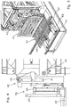
- a plant 10 for the automatic loading of a container comprises a park area 11, where the container 12 to be loaded is arranged, preferably mounted on a vehicle.
- the container 12 is completely closed on all sides and has only one access, closable with doors, in the rear part thereof.
- the plant 10 comprises a double conveyor 15 for transporting the pallets of sacks 14 from the conveyor 13 towards the container 12.
- the conveyor 15 is movable from a loading position at the conveyor 13 to a seizing position located behind the container 12.
- the conveyor 13 feeds a multiple chain conveyor 16, whose branches are placed cantilevered, and which can be lifted and lowered by means of a hydraulic actuator 17.
- the conveyor chains 16 are supported and moved by the hydraulic actuator 17.
- the conveyor 15 is formed by two movable carriages 20 sliding on rails 22 and joined together by a system that allows moving the latter near or apart.
- the direction of the rails 22 is perpendicular to the direction of the conveyor 13 and also perpendicular to the long side of the container 12.
- the movable carriages 20 comprise at the top a plurality of prongs 23 spaced apart so that the chains of the conveyor 16 can be inserted between the same.
- the prongs 23 are also cantilevered, i.e. are borne only by a vertical structure, belonging to the movable carriages 20, placed at the side near the container 12.
- the height of the movable carriages 20 is shorter (about 20 cm) than the height of the conveyor 13.
- a base 30 is provided carrying a guide 31.
- the guide 31 is constituted by a portion of a Long type truss.
- a Vierendeel-type beam 32 can slide inside the guide 31.
- the guide 31 at the front rests on two supports 33 near the container 12 and is fixed by means of a pin 35 on two rear supports 34.
- the supports 33 and 34 are part of the base 30.
- the guide 31 is formed by beams joined together and having towards the inside a plurality of upper and lower wheels 36, on which the beam 32 can slide.
- the beam 32 can slide horizontally inside the guide 31 by the actuation of a pair of chains 37 placed on the side of the beam 32.
- the beam 32 supports a structure 40, which comprises a pair of vertical lifters 41 that can vertically lift the portion 42, of the structure 40, fixed in front of the same (40).
- the lifter 41 also comprises actuators 43 to tilt forward by few degrees the lifter 41 and the portion 42 rotating around the pin 49.
- the portion 42 supports a horizontal seizing apparatus 44, commonly called fork, having a plurality of prongs 48.
- the portion 42 also comprises a pantograph structure 46 extending on command, connected to a panel 47.
- the pantograph 46 is arranged above the fork 44.
- a support system 50 of the beam 32 is located in the base 30, between the guide 31 and the container 12 . In the rest position, while the pallets of sacks 14 are loaded on the fork 44, the support system 50 remains horizontal to not interfere with the operations that take place above it.
- the support system 50 When the beam 32 begins to enter inside the container 12, the support system 50 is lifted, being possible for the latter to rotate about a pin 51, placed close to the container 12. At the ends of the support system 50 wheels 52 are placed on which the beam 32 can rest and slide.
- the plant for the loading of a container is automatic so all the means used are motorized and controlled by a computerized control center with the use of several sensors. Said elements will not be described in detail since, after the reading of this document, a person skilled in the art is able to manufacture the same.
- the second carriage 20 approaches the first carriage 20 ( Figure 10 ) so that the pallet of sacks 14 are arranged side by side. Both move and align themselves to the fork 44, ( Figure 11 and 12 ) which in the meantime was positioned lower than the prongs 23 so as not to interfere with the arriving carriages 20.
- the fork 44 is as wide as the two pallets of sacks 14 side by side.
- the lifter 41 lifts the structure 40 ( Figure 12 ) and in particular the prongs of the fork 44 pass through the prongs 23 of the carriages 20.
- the lifters 41 are inclined by a few degrees (for example approximately 3°) ( Figure 14 ), so as to lift the tip of the fork 44 and better hold the pallet of sacks 14.
- the beam 32 is advanced ( Figure 15 ), along the guide 31, bringing the fork 44 inside the container 12.
- the support system 50 is lifted ( Figure 16 ) and the beam 32 rests on the wheels 52 and moves forward until being positioned at the point ( Figure 17 ) in which the stack of sacks 14 must be unloaded.
- the lifter 41 is inclined downward ( Figure 18 ) and the fork 44 returns to the starting position.
- the fork 44 is lowered ( Figure 19 ) to be positioned on (or close to) the floor of the container 12.
- the pantograph 46 extends ( Figure 20 ) positioning the second panel 47 against the pallet of sacks 14, and at the same time the beam 32 is retracted at the same speed, so that the pallet of sacks 14 remains in the desired position, unloading from the fork 44.
- the arrangement in height of the conveyor 16, of the movable carriages 20 and of the fork 44 allows the lateral sliding of the same (20) without interference.
- the positioning of the support system 50, of the beam 32, as close as possible to the container 12 allows the beam to extend inside the container 12 with greater ease.
- the guide 31 is supported by two front supports 33 (towards the container 12) and by means of a pair of pins 35, placed on the rear supports 34, in order not to create a constraint to the rotation about the pin to avoid hyperstatic and non-immediately quantifiable reactions during the extension of the beam 32 when resting on the support 50.
- the vehicle carrying the container 12 must arrive at the park area 11 in reverse, and to obtain a correct alignment with the fork 44, it is provided that the front portion 42 of the structure 40 can move sideways sliding along guides 45.
- the entire base 30, with the guide 31, the beam 32 and the structure 40 can move sideways by a few meters sliding along rails 55 so that the arriving vehicle can pass between the base 30 and the conveyor 16 facing forward.
- the base 30 returns to the loading position behind the opening of the container 12.
- the size of the plant which in one embodiment has a beam 32 comprising the fork 44 of length 18 m, with sides of 1.25 m and 1.5 m, a weight of 8 t and a fork 2 m wide and 1.2 m long, may be any according to requirements and the state of the art.
- the fork In the case of the presence of pallets carrying the sacks 14, the fork would have a different shape and comprising only four prongs to support the two pallets. In this case it would not be necessary the pantograph to release the sacks as just retracting the fork from the pallets would be needed.
Description
- The present invention relates to a plant and to a method for the automatic loading of a container with palletized merchandise/goods.
- In particular, the present invention finds its application in the automatic loading of pallets (or ordered stacks) of sacks in a container. The invention can, however, refer to the loading of other materials palletized or arranged in ordered piles.
- The containers are completely closed and have only one rear opening, therefore it can be deduced that the filling thereof is quite problematic having little space for inserting the load.
- In the following, reference will be made to a container, but the invention also applies to trucks opened only at the rear.
-
EP 0 029 817 A1 discloses a device for loading freight units into a freight container comprising a carriage movable along a first direction and having an upper loading plane formed by conveyor rollers, a beam arranged slidable in a guide along a second direction perpendicular to the first direction, a seizing apparatus having a fork with prongs being associated to an end of the beam. The carriage is movable from a first position for receiving a freight unit on the loading plane to a second position in a loading station between the open end of the container and the end of the bean and where the loading plane is located at a lower level than the fork in order to allow the prongs of the fork to be inserted in the room of a pallet.EP 0 029 817 A1 further discloses a method for the automatic loading of a container with pallets of sacks comprising the steps of: providing pallets of sacks to at least one movable carriage along a first direction; placing a guide aligned with said container; a beam being slidable inside said guide along a second direction perpendicular to said first direction; arrange a seizing apparatus, having prongs, associated to one end of said beam; moving said movable carriage from a first position for receiving said pallets of sacks to a second position where the seizing apparatus can insert the fork in the room of the pallet. -
WO 2014/206418 A1 discloses a plant for loading a compartment of a road transport vehicle with stacks of sacks comprising a parking area, a carriage movable from a loading to a pick-up position and having an upper chain conveyor defining a support surface. Additionally, the plant comprises a handling member comprising a wagon movable along a pair of tracks arranged above the parking area and a fork movable along an upright of the wagon. In the pick-up position the carriage is located in front the rear opening of the compartment of the vehicle and the fork of the handling member is moved to a position on the opposite side of the carriage. Then the prongs of the fork are moved into the interspaces of the conveyor and the stack of sacks lifted off the carriage. Thereafter the stack of sacks can be moved to the desired position of compartment. - The object of the present invention is to provide a plant, for the automatic loading of a container with pallet of sacks, having dimensions compatible with the container.
- According to the present invention, these and further objects are achieved by a plant for the automatic loading of a container with ordered stacks of sacks comprising: at least one movable carriage movable along a first direction; said movable carriage having a plurality of first prongs placed cantilevered; a guide aligned with said container; a beam sliding inside said guide along a second direction perpendicular to said first direction; a seizing apparatus, having second prongs, associated to one end of said beam; said second prongs being insertable with said first prongs; said at least one movable carriage being movable from a first position for receiving said ordered stacks of sacks on said first prongs, to a second position where said first prongs are located above said second prongs; said second prongs being vertically movable; said beam being longitudinally movable to enter inside said container.
- Said objects are also achieved by a method for the automatic loading of a container with pallets of sacks comprising the steps of: providing at least one movable carriage movable along a first direction with the pallet of sacks; said movable carriage having a plurality of first prongs placed cantilevered; arranging a guide aligned with said container; a beam being slidable inside said guide along a second direction perpendicular to said first direction; arranging a seizing apparatus, having second prongs, associated to one end of said beam; said second prongs being insertable with said first prongs; moving said movable carriage from a first position for receiving said pallets of sacks on said first prongs, to a second position where said first prongs are located on the top of said seizing apparatus; move vertically said seizing apparatus; move longitudinally said beam to enter inside said container.
- Further characteristics of the invention are described in the dependent claims.
- The advantages of this solution with respect to the solutions of the known art are various.
- This solution allows to automatically load the container or other carriers that are completely closed and have only one rear opening that can be opened.
- It allows not to rest on the floor of the container and has enough clearance to be able to load without interfering with the container itself.
- The arrangement of the carriages, transversal with respect to the beam, their conformation allowing the loading and the withdrawal of the stacks of sacks by means of the fork, allows to position the beam as close as possible to the container thereby minimizing mechanical stress thereon while also reducing its length, in particular the cantilevered portion. Thanks also to the support system of the beam, which is retractable.
- Furthermore the guide is fastened by means of a pair of supports and of a pair of pins to avoid hyperstatic loads in the structure.
- The characteristics and advantages of the present invention will become apparent from the following detailed description of an embodiment thereof, illustrated by way of nonlimiting example in the accompanying drawings, wherein:
-
Figure 1 shows a plant for the automatic loading of a container, comprising the container, seen in axonometric view, according to the present invention; -
Figure 2 shows a plant for the automatic loading of a container, seen in axonometric view, according to the present invention; -
Figure 3 shows the lateral section of a central portion of a plant for the automatic loading of a container, according to the present invention; -
Figure 4 shows the seizing and storage equipment of a plant for the automatic loading of a container, seen from the side, according to the present invention; -
Figure 5 shows the seizing and storage equipment of a plant for the automatic loading of a container, seen in axonometric view, according to the present invention; -
Figure 6 shows a multiple chain conveyor of a plant for the automatic loading of a container, seen in axonometric view, according to the present invention; -
Figures 7-19 show the sequence for loading a container, according to the present invention. - A
plant 10 for the automatic loading of a container, according to the present invention, comprises apark area 11, where thecontainer 12 to be loaded is arranged, preferably mounted on a vehicle. Thecontainer 12 is completely closed on all sides and has only one access, closable with doors, in the rear part thereof. - A
conveyor 13, preferably of the belt type, transports the pallet ofsacks 14 laterally to the park area. - Near the park area, the
plant 10 comprises adouble conveyor 15 for transporting the pallets ofsacks 14 from theconveyor 13 towards thecontainer 12. - In particular, the
conveyor 15 is movable from a loading position at theconveyor 13 to a seizing position located behind thecontainer 12. - The
conveyor 13 feeds amultiple chain conveyor 16, whose branches are placed cantilevered, and which can be lifted and lowered by means of ahydraulic actuator 17. Theconveyor chains 16 are supported and moved by thehydraulic actuator 17. - The
conveyor 15 is formed by twomovable carriages 20 sliding onrails 22 and joined together by a system that allows moving the latter near or apart. The direction of therails 22 is perpendicular to the direction of theconveyor 13 and also perpendicular to the long side of thecontainer 12. - The
movable carriages 20 comprise at the top a plurality ofprongs 23 spaced apart so that the chains of theconveyor 16 can be inserted between the same. - The
prongs 23 are also cantilevered, i.e. are borne only by a vertical structure, belonging to themovable carriages 20, placed at the side near thecontainer 12. - The height of the
movable carriages 20 is shorter (about 20 cm) than the height of theconveyor 13. - At the rear of the park area and consequently at the rear of the container 12 a
base 30 is provided carrying aguide 31. Theguide 31 is constituted by a portion of a Long type truss. - A Vierendeel-
type beam 32 can slide inside theguide 31. - The
guide 31 at the front rests on two supports 33 near thecontainer 12 and is fixed by means of apin 35 on tworear supports 34. Thesupports base 30. - The
guide 31 is formed by beams joined together and having towards the inside a plurality of upper andlower wheels 36, on which thebeam 32 can slide. - The
beam 32 can slide horizontally inside theguide 31 by the actuation of a pair ofchains 37 placed on the side of thebeam 32. - At the front, in the vicinity of the
container 12, thebeam 32 supports astructure 40, which comprises a pair ofvertical lifters 41 that can vertically lift theportion 42, of thestructure 40, fixed in front of the same (40). - The
lifter 41 also comprisesactuators 43 to tilt forward by few degrees thelifter 41 and theportion 42 rotating around thepin 49. - The
portion 42 supports ahorizontal seizing apparatus 44, commonly called fork, having a plurality ofprongs 48. - The
portion 42 also comprises apantograph structure 46 extending on command, connected to apanel 47. Thepantograph 46 is arranged above thefork 44. In thebase 30, between theguide 31 and the container 12 asupport system 50 of thebeam 32 is located. In the rest position, while the pallets ofsacks 14 are loaded on thefork 44, thesupport system 50 remains horizontal to not interfere with the operations that take place above it. - When the
beam 32 begins to enter inside thecontainer 12, thesupport system 50 is lifted, being possible for the latter to rotate about apin 51, placed close to thecontainer 12. At the ends of thesupport system 50wheels 52 are placed on which thebeam 32 can rest and slide. - The plant for the loading of a container is automatic so all the means used are motorized and controlled by a computerized control center with the use of several sensors. Said elements will not be described in detail since, after the reading of this document, a person skilled in the art is able to manufacture the same.
- The operation of the invention is apparent for the skilled in the art from what has been described and, in particular, is the following:
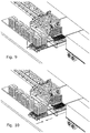
- The pallets of the
sacks 14 arrive in succession from the conveyor 13 (Figure 7 ) and reach theconveyor belt 16 that is initially aligned and at the same height of theconveyor 13. The pallets ofsacks 14 may or may not have the underlying pallet. - The chains of the
conveyor 16 are lowered on the underlying firstmovable carriage 20, pass through theprongs 23, and the pallet ofsacks 14 is laid upon it. - The first
movable carriage 20 moves towards thefork 44 so that thesecond carriage 20 is aligned with the conveyor 16 (Figure 7 ). - Then the chains of the
conveyor 16, which remained below theprongs 23, are lifted and are positioned back at the height of theconveyor 13 so as to receive the new pallet of sacks 14 (Figure 8 ). - Also in this case, once the pallet of
sacks 14 has arrived on the chains of theconveyor 16, they are lowered (Figure 9 ) positioning the second pallet ofsacks 14 on the secondmovable carriage 20. - The
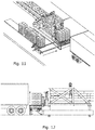
second carriage 20 approaches the first carriage 20 (Figure 10 ) so that the pallet ofsacks 14 are arranged side by side. Both move and align themselves to thefork 44, (Figure 11 and 12 ) which in the meantime was positioned lower than theprongs 23 so as not to interfere with the arrivingcarriages 20. Thefork 44 is as wide as the two pallets ofsacks 14 side by side. - The
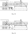
lifter 41 lifts the structure 40 (Figure 12 ) and in particular the prongs of thefork 44 pass through theprongs 23 of thecarriages 20. Thelifters 41 are inclined by a few degrees (for example approximately 3°) (Figure 14 ), so as to lift the tip of thefork 44 and better hold the pallet ofsacks 14. - The
beam 32 is advanced (Figure 15 ), along theguide 31, bringing thefork 44 inside thecontainer 12. - As soon as the
beam 32 enters thecontainer 12, thesupport system 50 is lifted (Figure 16 ) and thebeam 32 rests on thewheels 52 and moves forward until being positioned at the point (Figure 17 ) in which the stack ofsacks 14 must be unloaded. - The
lifter 41 is inclined downward (Figure 18 ) and thefork 44 returns to the starting position. Thefork 44 is lowered (Figure 19 ) to be positioned on (or close to) the floor of thecontainer 12. - To unload the pallet of sacks on 14 the floor of the
container 12, thepantograph 46 extends (Figure 20 ) positioning thesecond panel 47 against the pallet ofsacks 14, and at the same time thebeam 32 is retracted at the same speed, so that the pallet ofsacks 14 remains in the desired position, unloading from thefork 44. - The
beam 32, with thefork 44, exits from the container, the pantograph is closed, thesupport system 50 is lowered and seizes the load of pallets of sacks on thefork 44. - The fact that the
fork 44, and thebeam 32 which supports it, do not rest in any way on the loading floor of thecontainer 12 allows that the loading of the same takes place without any concern about the state of thecontainer 12. In fact, loading equipment that rests on the floor of the container could create problems if the latter is not in good condition. - The loading of the pallet of
sacks 14 coming from the side with respect to thebeam 32 and at theprongs 48 allows thefork 44 to be as close as possible to thecontainer 12, and therefore decrease the cantilevered length of thebeam 32. - The arrangement in height of the
conveyor 16, of themovable carriages 20 and of thefork 44 allows the lateral sliding of the same (20) without interference. The fact that theprongs 23, cantilevered, of themovable carriages 20, are insertable with the chains of theconveyor 16, as well as with the prongs of thefork 44, allows vertical movement. - The positioning of the
support system 50, of thebeam 32, as close as possible to thecontainer 12 allows the beam to extend inside thecontainer 12 with greater ease. Theguide 31 is supported by two front supports 33 (towards the container 12) and by means of a pair ofpins 35, placed on the rear supports 34, in order not to create a constraint to the rotation about the pin to avoid hyperstatic and non-immediately quantifiable reactions during the extension of thebeam 32 when resting on thesupport 50. - The vehicle carrying the
container 12 must arrive at thepark area 11 in reverse, and to obtain a correct alignment with thefork 44, it is provided that thefront portion 42 of thestructure 40 can move sideways sliding along guides 45. - In addition to facilitating the parking of the vehicle carrying the
container 12 in the loading position, it can be provided that theentire base 30, with theguide 31, thebeam 32 and thestructure 40, can move sideways by a few meters sliding alongrails 55 so that the arriving vehicle can pass between the base 30 and theconveyor 16 facing forward. - Once the vehicle is positioned in the park area the base 30 returns to the loading position behind the opening of the
container 12. - In an alternative embodiment one can plan to use one carriage only 20 (instead of two) and consequently to have a
fork 44 of reduced size, to load one pallet ofsacks 14 at a time. - The size of the plant, which in one embodiment has a
beam 32 comprising thefork 44 of length 18 m, with sides of 1.25 m and 1.5 m, a weight of 8 t and a fork 2 m wide and 1.2 m long, may be any according to requirements and the state of the art. - A more robust structure than that set forth above could also be used and avoid the use of the
support system 50. - In the case of the presence of pallets carrying the
sacks 14, the fork would have a different shape and comprising only four prongs to support the two pallets. In this case it would not be necessary the pantograph to release the sacks as just retracting the fork from the pallets would be needed.
Claims (13)
- A plant for the automatic loading of a container with ordered stacks of sacks (14) comprising: at least one movable carriage (20) along a first direction; said movable carriage (20) having a plurality of first prongs (23) placed cantilevered; a guide (31) aligned with said container (12); a beam (32) sliding inside said guide (31) along a second direction perpendicular to said first direction; a seizing apparatus (44), having second prongs (48), associated to one end of said beam (32); said second prongs (48) being insertable with said first prongs (23); said at least one movable carriage (20) being movable from a first position for receiving said ordered stacks of sacks (14) on said first prongs (23), to a second position where said first prongs (23) are located above said second prongs (48); said second prongs (48) being vertically movable; said beam (32) being longitudinally movable to enter inside said container (12).
- The plant according to claim 1 characterized by comprising a support system (50) of said beam (32), placed next to said container (12), liftable and supporting said beam (32) when the latter enters inside said container (12).
- The plant according to one of the preceding claims, characterized in that said seizing apparatus (44) is associated with one end of said beam (32) by means of a pantograph (46) extendable and retractable on command.
- The plant according to one of the preceding claims, characterized in that said seizing apparatus (44) is tiltable.
- The plant according to one of the preceding claims, characterized in that said guide (31) is a portion of truss with upper and lower wheels (36), in contact on the inside of said beam (32).
- The plant according to one of the preceding claims characterized by comprising a conveyor (13) that provides ordered stacks of sacks (14) to said at least one carriage (20).
- The plant according to claim 6 characterized by comprising a chain conveyor (16) placed cantilevered at the end of said conveyor (13); said chains being insertable with said first prongs (23).
- The plant according to one of the preceding claims characterized by comprising two movable carriages (20).
- The plant according to one of the preceding claims characterized by comprising a base (30) bearing said guide (31); said base being movable along said first direction.
- The plant according to one of the preceding claims, characterized in that the width of said seizing apparatus (44) is substantially equal to the width of said two carriages (20).
- The plant according to one of the preceding claims, characterized in that said guide (31) is located in front on two supports (33) and is fixed by means of a pin (35) on two rear supports (34).
- A method for the automatic loading of a container with pallets of sacks comprising the steps of: providing pallets of sacks to at least one movable carriage (20) along a first direction; said movable carriage (20) having a plurality of first prongs (23) placed cantilevered; placing a guide (31) aligned with said container (12); a beam (32) being slidable inside said guide (31) along a second direction perpendicular to said first direction; arrange a seizing apparatus (44), having second prongs (48), associated to one end of said beam (32); said second prongs (48) being insertable with said first prongs (23); moving said movable carriage (20) from a first position for receiving said pallets of sacks on said first prongs (23), to a second position where said first prongs are located on the top of said seizing apparatus (44); vertically moving said seizing apparatus (44); longitudinally moving said beam (32) to enter inside said container (12).
- The method according to the preceding claim characterized by further comprising the step of lifting a support system (50) of said beam (32), placed next to said container (12), when the latter enters inside said container (12).
Applications Claiming Priority (2)
| Application Number | Priority Date | Filing Date | Title |
|---|---|---|---|
| DKPA201570822 | 2015-12-14 | ||
| PCT/EP2016/080866 WO2017102771A1 (en) | 2015-12-14 | 2016-12-14 | Plant and method for the automatic loading of a container |
Publications (2)
| Publication Number | Publication Date |
|---|---|
| EP3390252A1 EP3390252A1 (en) | 2018-10-24 |
| EP3390252B1 true EP3390252B1 (en) | 2021-10-06 |
Family
ID=59055880
Family Applications (1)
| Application Number | Title | Priority Date | Filing Date |
|---|---|---|---|
| EP16810365.3A Active EP3390252B1 (en) | 2015-12-14 | 2016-12-14 | Plant and method for the automatic loading of a container |
Country Status (3)
| Country | Link |
|---|---|
| EP (1) | EP3390252B1 (en) |
| ES (1) | ES2895136T3 (en) |
| WO (1) | WO2017102771A1 (en) |
Families Citing this family (1)
| Publication number | Priority date | Publication date | Assignee | Title |
|---|---|---|---|---|
| CN109353849B (en) * | 2018-12-13 | 2023-09-22 | 合肥泰禾智能科技集团股份有限公司 | Loading walking guiding system and loading walking guiding method |
Family Cites Families (4)
| Publication number | Priority date | Publication date | Assignee | Title |
|---|---|---|---|---|
| SE429541B (en) * | 1979-11-22 | 1983-09-12 | Volvo Ab | SET AND DEVICE FOR LOADING UNITS IN A CONTAINER |
| ES2436764T3 (en) * | 2005-12-22 | 2014-01-07 | Actiw Oy | Transfer plate and procedure for loading a cargo space |
| ES2545124T3 (en) * | 2012-10-03 | 2015-09-08 | Montajes De Maquinaría De Precisión, S.A. | Automatic loading and unloading system for trucks and containers |
| EP3013724A1 (en) * | 2013-06-24 | 2016-05-04 | FLSmidth A/S | Plant and method for loading road transport vehicles with sacks of loose material |
-
2016
- 2016-12-14 WO PCT/EP2016/080866 patent/WO2017102771A1/en active Application Filing
- 2016-12-14 ES ES16810365T patent/ES2895136T3/en active Active
- 2016-12-14 EP EP16810365.3A patent/EP3390252B1/en active Active
Also Published As
| Publication number | Publication date |
|---|---|
| ES2895136T3 (en) | 2022-02-17 |
| WO2017102771A1 (en) | 2017-06-22 |
| EP3390252A1 (en) | 2018-10-24 |
Similar Documents
| Publication | Publication Date | Title |
|---|---|---|
| US7575407B2 (en) | Article storage facility | |
| EP1704071B1 (en) | Multiple platform aircraft cargo loader | |
| KR101562449B1 (en) | Vehicle goods bracket and vehicle goods bracket set | |
| KR20210088751A (en) | Method and apparatus for storing and retrieving or shifting containers in high-bay warehouses | |
| JPH021043B2 (en) | ||
| EP3390252B1 (en) | Plant and method for the automatic loading of a container | |
| US4010856A (en) | Storage apparatus with slide assemblies and a transportation device with pivotal conveyor means | |
| JPH0336738B2 (en) | ||
| EP4341174A1 (en) | A storage column module for coupling to a framework structure of an automated storage and retrieval system | |
| JP5420286B2 (en) | Transport device | |
| US20230192425A1 (en) | Apparatus and method for unloading and loading a transport unit | |
| JP7331445B2 (en) | stacker crane | |
| JP2000264406A (en) | Automatic warehouse with bridging function | |
| CN213294087U (en) | Side automatic loading and unloading equipment | |
| JP2594050Y2 (en) | Long heavy goods storage warehouse | |
| CN217262383U (en) | Automatic carrying and connecting system | |
| EP4296200A1 (en) | Article storage facility | |
| US20230391549A1 (en) | An access station for an automated storage and retrieval system with container tilt functionality and a method for using same | |
| KR200277232Y1 (en) | Cart for stacking freight | |
| WO2023061835A1 (en) | A delivery port for delivery of goods contained in goods holders | |
| CN111845962A (en) | Loading and unloading truck and cargo loading and unloading method for loading and unloading truck | |
| NO20211118A1 (en) | A container buffering assembly, a storage system comprising the container buffering assembly, and associated methods | |
| CN115744018A (en) | Shuttle car and multi-pass vertical warehouse access system | |
| CN115924373A (en) | Lifting machine, three-dimensional storage device and storage system | |
| JP2024025384A (en) | Automatic warehouse |
Legal Events
| Date | Code | Title | Description |
|---|---|---|---|
| STAA | Information on the status of an ep patent application or granted ep patent |
Free format text: STATUS: UNKNOWN |
|
| STAA | Information on the status of an ep patent application or granted ep patent |
Free format text: STATUS: THE INTERNATIONAL PUBLICATION HAS BEEN MADE |
|
| PUAI | Public reference made under article 153(3) epc to a published international application that has entered the european phase |
Free format text: ORIGINAL CODE: 0009012 |
|
| STAA | Information on the status of an ep patent application or granted ep patent |
Free format text: STATUS: REQUEST FOR EXAMINATION WAS MADE |
|
| 17P | Request for examination filed |
Effective date: 20180705 |
|
| AK | Designated contracting states |
Kind code of ref document: A1 Designated state(s): AL AT BE BG CH CY CZ DE DK EE ES FI FR GB GR HR HU IE IS IT LI LT LU LV MC MK MT NL NO PL PT RO RS SE SI SK SM TR |
|
| AX | Request for extension of the european patent |
Extension state: BA ME |
|
| DAV | Request for validation of the european patent (deleted) | ||
| DAX | Request for extension of the european patent (deleted) | ||
| GRAP | Despatch of communication of intention to grant a patent |
Free format text: ORIGINAL CODE: EPIDOSNIGR1 |
|
| STAA | Information on the status of an ep patent application or granted ep patent |
Free format text: STATUS: GRANT OF PATENT IS INTENDED |
|
| INTG | Intention to grant announced |
Effective date: 20210506 |
|
| GRAS | Grant fee paid |
Free format text: ORIGINAL CODE: EPIDOSNIGR3 |
|
| GRAA | (expected) grant |
Free format text: ORIGINAL CODE: 0009210 |
|
| STAA | Information on the status of an ep patent application or granted ep patent |
Free format text: STATUS: THE PATENT HAS BEEN GRANTED |
|
| AK | Designated contracting states |
Kind code of ref document: B1 Designated state(s): AL AT BE BG CH CY CZ DE DK EE ES FI FR GB GR HR HU IE IS IT LI LT LU LV MC MK MT NL NO PL PT RO RS SE SI SK SM TR |
|
| REG | Reference to a national code |
Ref country code: GB Ref legal event code: FG4D |
|
| REG | Reference to a national code |
Ref country code: CH Ref legal event code: EP Ref country code: AT Ref legal event code: REF Ref document number: 1436060 Country of ref document: AT Kind code of ref document: T Effective date: 20211015 |
|
| REG | Reference to a national code |
Ref country code: IE Ref legal event code: FG4D |
|
| REG | Reference to a national code |
Ref country code: DE Ref legal event code: R096 Ref document number: 602016064689 Country of ref document: DE |
|
| REG | Reference to a national code |
Ref country code: LT Ref legal event code: MG9D |
|
| REG | Reference to a national code |
Ref country code: NL Ref legal event code: MP Effective date: 20211006 |
|
| REG | Reference to a national code |
Ref country code: ES Ref legal event code: FG2A Ref document number: 2895136 Country of ref document: ES Kind code of ref document: T3 Effective date: 20220217 |
|
| REG | Reference to a national code |
Ref country code: AT Ref legal event code: MK05 Ref document number: 1436060 Country of ref document: AT Kind code of ref document: T Effective date: 20211006 |
|
| PG25 | Lapsed in a contracting state [announced via postgrant information from national office to epo] |
Ref country code: RS Free format text: LAPSE BECAUSE OF FAILURE TO SUBMIT A TRANSLATION OF THE DESCRIPTION OR TO PAY THE FEE WITHIN THE PRESCRIBED TIME-LIMIT Effective date: 20211006 Ref country code: LT Free format text: LAPSE BECAUSE OF FAILURE TO SUBMIT A TRANSLATION OF THE DESCRIPTION OR TO PAY THE FEE WITHIN THE PRESCRIBED TIME-LIMIT Effective date: 20211006 Ref country code: FI Free format text: LAPSE BECAUSE OF FAILURE TO SUBMIT A TRANSLATION OF THE DESCRIPTION OR TO PAY THE FEE WITHIN THE PRESCRIBED TIME-LIMIT Effective date: 20211006 Ref country code: BG Free format text: LAPSE BECAUSE OF FAILURE TO SUBMIT A TRANSLATION OF THE DESCRIPTION OR TO PAY THE FEE WITHIN THE PRESCRIBED TIME-LIMIT Effective date: 20220106 Ref country code: AT Free format text: LAPSE BECAUSE OF FAILURE TO SUBMIT A TRANSLATION OF THE DESCRIPTION OR TO PAY THE FEE WITHIN THE PRESCRIBED TIME-LIMIT Effective date: 20211006 |
|
| PG25 | Lapsed in a contracting state [announced via postgrant information from national office to epo] |
Ref country code: IS Free format text: LAPSE BECAUSE OF FAILURE TO SUBMIT A TRANSLATION OF THE DESCRIPTION OR TO PAY THE FEE WITHIN THE PRESCRIBED TIME-LIMIT Effective date: 20220206 Ref country code: SE Free format text: LAPSE BECAUSE OF FAILURE TO SUBMIT A TRANSLATION OF THE DESCRIPTION OR TO PAY THE FEE WITHIN THE PRESCRIBED TIME-LIMIT Effective date: 20211006 Ref country code: PT Free format text: LAPSE BECAUSE OF FAILURE TO SUBMIT A TRANSLATION OF THE DESCRIPTION OR TO PAY THE FEE WITHIN THE PRESCRIBED TIME-LIMIT Effective date: 20220207 Ref country code: PL Free format text: LAPSE BECAUSE OF FAILURE TO SUBMIT A TRANSLATION OF THE DESCRIPTION OR TO PAY THE FEE WITHIN THE PRESCRIBED TIME-LIMIT Effective date: 20211006 Ref country code: NO Free format text: LAPSE BECAUSE OF FAILURE TO SUBMIT A TRANSLATION OF THE DESCRIPTION OR TO PAY THE FEE WITHIN THE PRESCRIBED TIME-LIMIT Effective date: 20220106 Ref country code: NL Free format text: LAPSE BECAUSE OF FAILURE TO SUBMIT A TRANSLATION OF THE DESCRIPTION OR TO PAY THE FEE WITHIN THE PRESCRIBED TIME-LIMIT Effective date: 20211006 Ref country code: LV Free format text: LAPSE BECAUSE OF FAILURE TO SUBMIT A TRANSLATION OF THE DESCRIPTION OR TO PAY THE FEE WITHIN THE PRESCRIBED TIME-LIMIT Effective date: 20211006 Ref country code: HR Free format text: LAPSE BECAUSE OF FAILURE TO SUBMIT A TRANSLATION OF THE DESCRIPTION OR TO PAY THE FEE WITHIN THE PRESCRIBED TIME-LIMIT Effective date: 20211006 Ref country code: GR Free format text: LAPSE BECAUSE OF FAILURE TO SUBMIT A TRANSLATION OF THE DESCRIPTION OR TO PAY THE FEE WITHIN THE PRESCRIBED TIME-LIMIT Effective date: 20220107 |
|
| REG | Reference to a national code |
Ref country code: DE Ref legal event code: R097 Ref document number: 602016064689 Country of ref document: DE |
|
| PG25 | Lapsed in a contracting state [announced via postgrant information from national office to epo] |
Ref country code: SM Free format text: LAPSE BECAUSE OF FAILURE TO SUBMIT A TRANSLATION OF THE DESCRIPTION OR TO PAY THE FEE WITHIN THE PRESCRIBED TIME-LIMIT Effective date: 20211006 Ref country code: SK Free format text: LAPSE BECAUSE OF FAILURE TO SUBMIT A TRANSLATION OF THE DESCRIPTION OR TO PAY THE FEE WITHIN THE PRESCRIBED TIME-LIMIT Effective date: 20211006 Ref country code: RO Free format text: LAPSE BECAUSE OF FAILURE TO SUBMIT A TRANSLATION OF THE DESCRIPTION OR TO PAY THE FEE WITHIN THE PRESCRIBED TIME-LIMIT Effective date: 20211006 Ref country code: MC Free format text: LAPSE BECAUSE OF FAILURE TO SUBMIT A TRANSLATION OF THE DESCRIPTION OR TO PAY THE FEE WITHIN THE PRESCRIBED TIME-LIMIT Effective date: 20211006 Ref country code: EE Free format text: LAPSE BECAUSE OF FAILURE TO SUBMIT A TRANSLATION OF THE DESCRIPTION OR TO PAY THE FEE WITHIN THE PRESCRIBED TIME-LIMIT Effective date: 20211006 Ref country code: DK Free format text: LAPSE BECAUSE OF FAILURE TO SUBMIT A TRANSLATION OF THE DESCRIPTION OR TO PAY THE FEE WITHIN THE PRESCRIBED TIME-LIMIT Effective date: 20211006 Ref country code: CZ Free format text: LAPSE BECAUSE OF FAILURE TO SUBMIT A TRANSLATION OF THE DESCRIPTION OR TO PAY THE FEE WITHIN THE PRESCRIBED TIME-LIMIT Effective date: 20211006 |
|
| REG | Reference to a national code |
Ref country code: CH Ref legal event code: PL |
|
| PLBE | No opposition filed within time limit |
Free format text: ORIGINAL CODE: 0009261 |
|
| STAA | Information on the status of an ep patent application or granted ep patent |
Free format text: STATUS: NO OPPOSITION FILED WITHIN TIME LIMIT |
|
| 26N | No opposition filed |
Effective date: 20220707 |
|
| REG | Reference to a national code |
Ref country code: BE Ref legal event code: MM Effective date: 20211231 |
|
| GBPC | Gb: european patent ceased through non-payment of renewal fee |
Effective date: 20220106 |
|
| PG25 | Lapsed in a contracting state [announced via postgrant information from national office to epo] |
Ref country code: LU Free format text: LAPSE BECAUSE OF NON-PAYMENT OF DUE FEES Effective date: 20211214 Ref country code: IE Free format text: LAPSE BECAUSE OF NON-PAYMENT OF DUE FEES Effective date: 20211214 Ref country code: GB Free format text: LAPSE BECAUSE OF NON-PAYMENT OF DUE FEES Effective date: 20220106 Ref country code: AL Free format text: LAPSE BECAUSE OF FAILURE TO SUBMIT A TRANSLATION OF THE DESCRIPTION OR TO PAY THE FEE WITHIN THE PRESCRIBED TIME-LIMIT Effective date: 20211006 |
|
| PG25 | Lapsed in a contracting state [announced via postgrant information from national office to epo] |
Ref country code: SI Free format text: LAPSE BECAUSE OF FAILURE TO SUBMIT A TRANSLATION OF THE DESCRIPTION OR TO PAY THE FEE WITHIN THE PRESCRIBED TIME-LIMIT Effective date: 20211006 Ref country code: BE Free format text: LAPSE BECAUSE OF NON-PAYMENT OF DUE FEES Effective date: 20211231 |
|
| PG25 | Lapsed in a contracting state [announced via postgrant information from national office to epo] |
Ref country code: LI Free format text: LAPSE BECAUSE OF NON-PAYMENT OF DUE FEES Effective date: 20211231 Ref country code: CH Free format text: LAPSE BECAUSE OF NON-PAYMENT OF DUE FEES Effective date: 20211231 |
|
| PGFP | Annual fee paid to national office [announced via postgrant information from national office to epo] |
Ref country code: ES Payment date: 20230112 Year of fee payment: 7 |
|
| PG25 | Lapsed in a contracting state [announced via postgrant information from national office to epo] |
Ref country code: HU Free format text: LAPSE BECAUSE OF FAILURE TO SUBMIT A TRANSLATION OF THE DESCRIPTION OR TO PAY THE FEE WITHIN THE PRESCRIBED TIME-LIMIT; INVALID AB INITIO Effective date: 20161214 |
|
| P01 | Opt-out of the competence of the unified patent court (upc) registered |
Effective date: 20230507 |
|
| PG25 | Lapsed in a contracting state [announced via postgrant information from national office to epo] |
Ref country code: CY Free format text: LAPSE BECAUSE OF FAILURE TO SUBMIT A TRANSLATION OF THE DESCRIPTION OR TO PAY THE FEE WITHIN THE PRESCRIBED TIME-LIMIT Effective date: 20211006 |
|
| PGFP | Annual fee paid to national office [announced via postgrant information from national office to epo] |
Ref country code: TR Payment date: 20231213 Year of fee payment: 8 Ref country code: IT Payment date: 20231110 Year of fee payment: 8 Ref country code: FR Payment date: 20231122 Year of fee payment: 8 Ref country code: DE Payment date: 20231031 Year of fee payment: 8 |