EP3789236A1 - Ladestation für ein elektrisch betriebenes fahrzeug - Google Patents
Ladestation für ein elektrisch betriebenes fahrzeug Download PDFInfo
- Publication number
- EP3789236A1 EP3789236A1 EP20189792.3A EP20189792A EP3789236A1 EP 3789236 A1 EP3789236 A1 EP 3789236A1 EP 20189792 A EP20189792 A EP 20189792A EP 3789236 A1 EP3789236 A1 EP 3789236A1
- Authority
- EP
- European Patent Office
- Prior art keywords
- charging
- cable
- charging cable
- charging station
- suspension
- Prior art date
- Legal status (The legal status is an assumption and is not a legal conclusion. Google has not performed a legal analysis and makes no representation as to the accuracy of the status listed.)
- Pending
Links
- 239000000725 suspension Substances 0.000 claims abstract description 37
- 238000004804 winding Methods 0.000 claims description 11
- 238000000034 method Methods 0.000 description 8
- RYGMFSIKBFXOCR-UHFFFAOYSA-N Copper Chemical compound [Cu] RYGMFSIKBFXOCR-UHFFFAOYSA-N 0.000 description 2
- 229910052802 copper Inorganic materials 0.000 description 2
- 239000010949 copper Substances 0.000 description 2
- 238000011161 development Methods 0.000 description 2
- 230000018109 developmental process Effects 0.000 description 2
- 239000000463 material Substances 0.000 description 2
- 239000004809 Teflon Substances 0.000 description 1
- 229920006362 Teflon® Polymers 0.000 description 1
- 238000005452 bending Methods 0.000 description 1
- 229910052751 metal Inorganic materials 0.000 description 1
- 239000002184 metal Substances 0.000 description 1
- 150000002739 metals Chemical class 0.000 description 1
- 239000004033 plastic Substances 0.000 description 1
Images


Classifications
-
- H—ELECTRICITY
- H02—GENERATION; CONVERSION OR DISTRIBUTION OF ELECTRIC POWER
- H02G—INSTALLATION OF ELECTRIC CABLES OR LINES, OR OF COMBINED OPTICAL AND ELECTRIC CABLES OR LINES
- H02G11/00—Arrangements of electric cables or lines between relatively-movable parts
- H02G11/003—Arrangements of electric cables or lines between relatively-movable parts using gravity-loaded or spring-loaded loop
-
- B—PERFORMING OPERATIONS; TRANSPORTING
- B60—VEHICLES IN GENERAL
- B60L—PROPULSION OF ELECTRICALLY-PROPELLED VEHICLES; SUPPLYING ELECTRIC POWER FOR AUXILIARY EQUIPMENT OF ELECTRICALLY-PROPELLED VEHICLES; ELECTRODYNAMIC BRAKE SYSTEMS FOR VEHICLES IN GENERAL; MAGNETIC SUSPENSION OR LEVITATION FOR VEHICLES; MONITORING OPERATING VARIABLES OF ELECTRICALLY-PROPELLED VEHICLES; ELECTRIC SAFETY DEVICES FOR ELECTRICALLY-PROPELLED VEHICLES
- B60L53/00—Methods of charging batteries, specially adapted for electric vehicles; Charging stations or on-board charging equipment therefor; Exchange of energy storage elements in electric vehicles
- B60L53/30—Constructional details of charging stations
-
- B—PERFORMING OPERATIONS; TRANSPORTING
- B60—VEHICLES IN GENERAL
- B60L—PROPULSION OF ELECTRICALLY-PROPELLED VEHICLES; SUPPLYING ELECTRIC POWER FOR AUXILIARY EQUIPMENT OF ELECTRICALLY-PROPELLED VEHICLES; ELECTRODYNAMIC BRAKE SYSTEMS FOR VEHICLES IN GENERAL; MAGNETIC SUSPENSION OR LEVITATION FOR VEHICLES; MONITORING OPERATING VARIABLES OF ELECTRICALLY-PROPELLED VEHICLES; ELECTRIC SAFETY DEVICES FOR ELECTRICALLY-PROPELLED VEHICLES
- B60L53/00—Methods of charging batteries, specially adapted for electric vehicles; Charging stations or on-board charging equipment therefor; Exchange of energy storage elements in electric vehicles
- B60L53/10—Methods of charging batteries, specially adapted for electric vehicles; Charging stations or on-board charging equipment therefor; Exchange of energy storage elements in electric vehicles characterised by the energy transfer between the charging station and the vehicle
- B60L53/14—Conductive energy transfer
- B60L53/18—Cables specially adapted for charging electric vehicles
-
- B—PERFORMING OPERATIONS; TRANSPORTING
- B65—CONVEYING; PACKING; STORING; HANDLING THIN OR FILAMENTARY MATERIAL
- B65H—HANDLING THIN OR FILAMENTARY MATERIAL, e.g. SHEETS, WEBS, CABLES
- B65H75/00—Storing webs, tapes, or filamentary material, e.g. on reels
- B65H75/02—Cores, formers, supports, or holders for coiled, wound, or folded material, e.g. reels, spindles, bobbins, cop tubes, cans, mandrels or chucks
- B65H75/34—Cores, formers, supports, or holders for coiled, wound, or folded material, e.g. reels, spindles, bobbins, cop tubes, cans, mandrels or chucks specially adapted or mounted for storing and repeatedly paying-out and re-storing lengths of material provided for particular purposes, e.g. anchored hoses, power cables
- B65H75/38—Cores, formers, supports, or holders for coiled, wound, or folded material, e.g. reels, spindles, bobbins, cop tubes, cans, mandrels or chucks specially adapted or mounted for storing and repeatedly paying-out and re-storing lengths of material provided for particular purposes, e.g. anchored hoses, power cables involving the use of a core or former internal to, and supporting, a stored package of material
-
- B—PERFORMING OPERATIONS; TRANSPORTING
- B65—CONVEYING; PACKING; STORING; HANDLING THIN OR FILAMENTARY MATERIAL
- B65H—HANDLING THIN OR FILAMENTARY MATERIAL, e.g. SHEETS, WEBS, CABLES
- B65H75/00—Storing webs, tapes, or filamentary material, e.g. on reels
- B65H75/02—Cores, formers, supports, or holders for coiled, wound, or folded material, e.g. reels, spindles, bobbins, cop tubes, cans, mandrels or chucks
- B65H75/34—Cores, formers, supports, or holders for coiled, wound, or folded material, e.g. reels, spindles, bobbins, cop tubes, cans, mandrels or chucks specially adapted or mounted for storing and repeatedly paying-out and re-storing lengths of material provided for particular purposes, e.g. anchored hoses, power cables
- B65H75/38—Cores, formers, supports, or holders for coiled, wound, or folded material, e.g. reels, spindles, bobbins, cop tubes, cans, mandrels or chucks specially adapted or mounted for storing and repeatedly paying-out and re-storing lengths of material provided for particular purposes, e.g. anchored hoses, power cables involving the use of a core or former internal to, and supporting, a stored package of material
- B65H75/44—Constructional details
- B65H75/4481—Arrangements or adaptations for driving the reel or the material
-
- F—MECHANICAL ENGINEERING; LIGHTING; HEATING; WEAPONS; BLASTING
- F16—ENGINEERING ELEMENTS AND UNITS; GENERAL MEASURES FOR PRODUCING AND MAINTAINING EFFECTIVE FUNCTIONING OF MACHINES OR INSTALLATIONS; THERMAL INSULATION IN GENERAL
- F16L—PIPES; JOINTS OR FITTINGS FOR PIPES; SUPPORTS FOR PIPES, CABLES OR PROTECTIVE TUBING; MEANS FOR THERMAL INSULATION IN GENERAL
- F16L3/00—Supports for pipes, cables or protective tubing, e.g. hangers, holders, clamps, cleats, clips, brackets
- F16L3/01—Supports for pipes, cables or protective tubing, e.g. hangers, holders, clamps, cleats, clips, brackets for supporting or guiding the pipes, cables or protective tubing, between relatively movable points, e.g. movable channels
- F16L3/012—Supports for pipes, cables or protective tubing, e.g. hangers, holders, clamps, cleats, clips, brackets for supporting or guiding the pipes, cables or protective tubing, between relatively movable points, e.g. movable channels using reels
-
- H—ELECTRICITY
- H02—GENERATION; CONVERSION OR DISTRIBUTION OF ELECTRIC POWER
- H02G—INSTALLATION OF ELECTRIC CABLES OR LINES, OR OF COMBINED OPTICAL AND ELECTRIC CABLES OR LINES
- H02G11/00—Arrangements of electric cables or lines between relatively-movable parts
- H02G11/02—Arrangements of electric cables or lines between relatively-movable parts using take-up reel or drum
-
- Y—GENERAL TAGGING OF NEW TECHNOLOGICAL DEVELOPMENTS; GENERAL TAGGING OF CROSS-SECTIONAL TECHNOLOGIES SPANNING OVER SEVERAL SECTIONS OF THE IPC; TECHNICAL SUBJECTS COVERED BY FORMER USPC CROSS-REFERENCE ART COLLECTIONS [XRACs] AND DIGESTS
- Y02—TECHNOLOGIES OR APPLICATIONS FOR MITIGATION OR ADAPTATION AGAINST CLIMATE CHANGE
- Y02T—CLIMATE CHANGE MITIGATION TECHNOLOGIES RELATED TO TRANSPORTATION
- Y02T10/00—Road transport of goods or passengers
- Y02T10/60—Other road transportation technologies with climate change mitigation effect
- Y02T10/70—Energy storage systems for electromobility, e.g. batteries
-
- Y—GENERAL TAGGING OF NEW TECHNOLOGICAL DEVELOPMENTS; GENERAL TAGGING OF CROSS-SECTIONAL TECHNOLOGIES SPANNING OVER SEVERAL SECTIONS OF THE IPC; TECHNICAL SUBJECTS COVERED BY FORMER USPC CROSS-REFERENCE ART COLLECTIONS [XRACs] AND DIGESTS
- Y02—TECHNOLOGIES OR APPLICATIONS FOR MITIGATION OR ADAPTATION AGAINST CLIMATE CHANGE
- Y02T—CLIMATE CHANGE MITIGATION TECHNOLOGIES RELATED TO TRANSPORTATION
- Y02T10/00—Road transport of goods or passengers
- Y02T10/60—Other road transportation technologies with climate change mitigation effect
- Y02T10/7072—Electromobility specific charging systems or methods for batteries, ultracapacitors, supercapacitors or double-layer capacitors
-
- Y—GENERAL TAGGING OF NEW TECHNOLOGICAL DEVELOPMENTS; GENERAL TAGGING OF CROSS-SECTIONAL TECHNOLOGIES SPANNING OVER SEVERAL SECTIONS OF THE IPC; TECHNICAL SUBJECTS COVERED BY FORMER USPC CROSS-REFERENCE ART COLLECTIONS [XRACs] AND DIGESTS
- Y02—TECHNOLOGIES OR APPLICATIONS FOR MITIGATION OR ADAPTATION AGAINST CLIMATE CHANGE
- Y02T—CLIMATE CHANGE MITIGATION TECHNOLOGIES RELATED TO TRANSPORTATION
- Y02T90/00—Enabling technologies or technologies with a potential or indirect contribution to GHG emissions mitigation
- Y02T90/10—Technologies relating to charging of electric vehicles
- Y02T90/12—Electric charging stations
-
- Y—GENERAL TAGGING OF NEW TECHNOLOGICAL DEVELOPMENTS; GENERAL TAGGING OF CROSS-SECTIONAL TECHNOLOGIES SPANNING OVER SEVERAL SECTIONS OF THE IPC; TECHNICAL SUBJECTS COVERED BY FORMER USPC CROSS-REFERENCE ART COLLECTIONS [XRACs] AND DIGESTS
- Y02—TECHNOLOGIES OR APPLICATIONS FOR MITIGATION OR ADAPTATION AGAINST CLIMATE CHANGE
- Y02T—CLIMATE CHANGE MITIGATION TECHNOLOGIES RELATED TO TRANSPORTATION
- Y02T90/00—Enabling technologies or technologies with a potential or indirect contribution to GHG emissions mitigation
- Y02T90/10—Technologies relating to charging of electric vehicles
- Y02T90/14—Plug-in electric vehicles
Definitions
- the invention relates to a charging station for charging a traction battery of an electrically operated vehicle according to the preamble of claim 1.
- a wall-mounted, mobile charging station or a charging station has a charging cable with a charging plug that can be plugged into the electrically operated vehicle for the charging process.
- the comparatively rigid copper charging cable must have a certain cable length in order to ensure flexible handling of the charging cable. The cable length can in turn lead to the charging cable twisting or coming into contact with the floor during the charging process and soiling.
- a generic charging station has a cable routing device by means of which the charging cable can be brought from its storage position at the charging station into a position of use in which the charging plug can be plugged into the vehicle by the vehicle user.
- the charging cable can be wrapped manually around a cable carrier in its storage station, but this is associated with a loss of comfort for the vehicle user.
- the object of the invention is to provide a charging station for charging a traction battery of an electrically operated vehicle, in which the charging process is more convenient with technically simple means compared to the prior art.
- the charging cable is not wound around a winding support of the charging station in its storage position.
- the charging station according to the characterizing part of claim 1 has an elastically flexible cable suspension which is connected to a connection point on the charging cable.
- the charging cable is moved from its storage position to its Position of use transferred by the vehicle user, in which the charging plug of the charging cable can be connected to the vehicle.
- the cable suspension is extended by a pull-out distance while a restoring force is built up.
- the charging plug is released from the vehicle, the charging cable together with the charging plug is automatically returned to its storage position, relieving the restoring force.
- the charging cable is suspended in a loop-like riser at a vertical distance from the floor.
- the basic idea of the invention is to store the charging cable in such a way that it does not have to be wound up and does not touch the ground. This can be achieved, for example, if a swiveling charging cable crane is used from which the charging cable is suspended.
- the size or height of the crane is designed according to the length and the bending radius of the cable.
- the cable length can also be varied by the height of the mounting of the charging station (i.e. the charging wallbox) on the wall.
- a cable pull system can be installed inside the crane, which pulls the charging cable back into the storage position or home position if necessary.
- the rope of the rope pull system is guided with pulleys inside the crane so that the shape of the crane can be adapted to the respective design characteristics.
- the number of pulleys can vary according to the crane design.
- the crane can be designed to be swiveling or rigid in order to simplify the handling of the charging cable in all directions.
- the cable pull system can be designed in different ways, for example it ideally has an automatic retraction system which ensures that the charging cable does not touch the ground and allows the cable to be tensioned to a certain extent while the vehicle is charging.
- the cable pull system can be designed with a corresponding spring system, which ensures comparable functions.
- a combination of a spring system and a cable pull system or a spring system with a cable is also possible in this implementation.
- the rope can be made of different materials. Current ropes are based on plastic materials or on metals.
- the pulleys can guide both the cable system and a corresponding spring system. The number of pulleys depends on both the system used and the crane design. Instead of the pulleys, other sliding guides are also possible, such as Teflon blocks or the like.
- the charging plug can be placed in a charging plug holder on the wall or on the charging wallbox.
- deflection systems or deflection pulleys
- the number of deflection systems depends on the design of the charging wallbox and the structural conditions. It is also possible to dispense with the crane. The rope pull system can still be used to the full.
- the handling of the charging cable is made more flexible and simpler. Particularly when the invention is carried out with the charging cable crane, the vehicle user's access to the charging cable can be further simplified. In addition, a crane can make the charging cable longer without it touching the ground. Because of the resilient charging cable suspension, twisting and tangling of the charging cable in its storage position and / or when the charging cable is in use can be prevented. It also prevents the charging cable from touching the floor and becoming dirty. The handling of the charging cable is thus simplified overall and more convenient for the user. In addition, the risk of wear and tear or damage to the charging cable is reduced.
- the connection point at which the cable suspension engages the charging cable can split the charging cable into a charging cable section leading away from the charging station and a free charging cable section, at the free end of which the Charging plug is designed.
- the suspension element is firmly connected to the charging cable at the connection point, in particular in a stationary manner in the longitudinal direction of the charging cable. In this way, the cable length of the free charging cable section (extends between the connection point and the charging plug) always remains constant, both in the position of use and in the storage position.
- the charging cable can preferably be suspended from the elastically flexible cable suspension in a loop-like elevation.
- the charging cable section leading away therefrom can be guided vertically upwards by a height offset to the suspension point, which forms an upper charging cable apex. From the upper charging cable apex, the free charging cable section can hang vertically downwards in opposite directions or be guided downwards.
- the charging cable is not wound around a winding carrier of the charging station in its storage position. Instead, the charging cable assumes a sinusoidal or meander-shaped charging cable course in its storage position, in particular with precisely one vertically upper charging cable apex directly at the connection point to the cable suspension.
- the two charging cable sections can be spaced apart from one another in the horizontal direction by a flank section.
- the edge distance between the charging cable sections increases.
- the height offset of the charging cable is reduced.
- the suspension element can be part of a spring system.
- the spring system can expand around the extension path when the charging cable is moved into its position of use. When the charging cable is returned to its storage position, the spring system contracts again around the extension path.
- the suspension element can be part of a cable system.
- the suspension element is tied to a rope.
- the rope can be wound on a winding drum which is spring-pretensioned in a winding direction.
- the charging cable is transferred into its position of use, the rope is therefore unwound around the extension path from the winding drum.
- the charging cable is returned to its storage position, the rope is automatically rewound onto the winding drum.
- the charging station is assigned an in particular pivotable charging cable support arm.
- the charging cable support arm can be part of a swiveling charging cable crane on which the suspension element is arranged. In this way, the suspension element can be positioned spatially at a distance from the charging station and, if necessary, at least partially project beyond the vehicle to be charged in the manner of a boom during the charging process.
- the charging cable be returned from its use position to its storage position by means of the spring pull / cable pull and / or through a clever arrangement of the pulleys, but also the pivoting charging cable support arm can also be returned to its storage position.
- the charging station can be assigned a charging plug holder on which the charging plug can be positioned in the charging cable storage position, protected from external mechanical influences.
- a wall-mounted charging station is shown roughly schematically, which is implemented as a wallbox as an example.
- the charging station is only indicated to the extent that it is necessary to understand the invention.
- the charging station has a copper charging cable 1, which is rigid to a certain extent, with a charging plug 3 which, during a charging process on the electrically operated vehicle 25 ( Figure 2 ) is attachable.
- the charging cable 1 is shown in its storage position, in which the charging plug 3 can be held in a wall-mounted charging plug holder 5.
- the charging cable 1 is held in its storage position in a loop-like riser on an elastically flexible cable suspension 7.
- the cable suspension 7 is part of a cable guide device which is provided on an upper side of the charging station.
- the cable routing device also has a cable pull system with deflection pulleys 11, over which a pull cable 13 is guided.
- a suspension element 15 which is fixedly connected to the charging cable 1 at a connection point A.
- connection point A divides the charging cable 1 into a charging cable section 17 leading away from the charging station and a free charging cable section 19 at its free end the charging plug 3 is formed.
- the pull rope 13 is wound onto a winding drum (not shown in the figures as a box at the left end of the pull rope 13) which is spring-biased in a winding direction.
- the suspension element 15 is positioned in an elastically resilient manner on the cable guide device.
- the cable guide device also has a charging cable crane 21 which can be pivoted about a vertical pivot axis S and has a support arm 23 protruding from the charging station.
- the suspension element 15 is positioned at the free end of the support arm 23.
- the charging cable 1 held on the cable suspension 7 assumes a sinusoidal or meandering charging cable course.
- the charging cable section 17 leading away from the charging station is guided vertically upwards by a height offset ⁇ h as far as the connection point A, which forms an upper charging cable apex 16.
- the free charging cable section 17 hangs vertically downward from the charging cable apex 16.
- the two charging cable sections 17, 19 are spaced apart from one another in a horizontal direction by an edge distance f.
- the charging cable 1 is shown in its position of use, in which the charging plug 3 is plugged into the electrically operated vehicle 25 by a vehicle user.
- the charging plug 3 is pulled by the vehicle user in the direction of the electrically operated vehicle 25.
- the pull rope 13 is unwound from the take-up reel by the pull-out path ⁇ a , building up a restoring force F R.
- the charging cable 1 is transferred from the storage position to the position of use, it is reduced according to FIG Figure 2 the charging cable height offset ⁇ h and the edge distance f between the two charging cable sections 17, 19 increases at the same time.
- the charging cable 1 In the position of use, the charging cable 1 continues to assume a sinusoidal or meander-shaped charging cable course, which is flatter compared to the storage position. Both in the storage position and in the position of use, the charging cable 1 extends reliably in an uplift at a distance from the floor.
- the user releases the charging plug 3 from the vehicle 25, whereby the charging cable 1 automatically returns to its storage position while reducing the restoring force F R ( Figure 1 ) is returned.
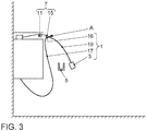
- the charging station according to a second embodiment is shown.
- the basic structure and the mode of operation of the resilient cable suspension 7 of the charging station is identical to the structure and the mode of operation of the cable suspension 7 according to the first exemplary embodiment.
- the cable routing device does not have an additional swiveling charging cable crane 21. Rather, the suspension element 15 is positioned directly on the charging station.
Landscapes
- Engineering & Computer Science (AREA)
- Mechanical Engineering (AREA)
- Power Engineering (AREA)
- Transportation (AREA)
- General Engineering & Computer Science (AREA)
- Charge And Discharge Circuits For Batteries Or The Like (AREA)
- Electric Propulsion And Braking For Vehicles (AREA)
Abstract
Description
- Die Erfindung betrifft eine Ladestation zum Aufladen einer Traktionsbatterie eines elektrisch betriebenen Fahrzeugs nach dem Oberbegriff des Anspruches 1.
- Eine wandmontierte, mobile oder als Ladesäule realisierte Ladestation weist ein Ladekabel mit einem Ladestecker auf, der für den Ladevorgang am elektrisch betriebenen Fahrzeug ansteckbar ist. Das vergleichsweise biegesteife Kupfer-Ladekabel muss eine gewisse Kabellänge haben, um eine flexible Handhabung des Ladekabels zu gewährleisten. Die Kabellänge kann wiederum dazu führen, dass sich das Ladekabel verdreht oder beim Ladevorgang in Kontakt mit dem Boden kommt und verschmutzt.
- Eine gattungsgemäße Ladestation weist eine Kabelführungseinrichtung auf, mittels der das Ladekabel von seiner Verwahrposition an der Ladestation in eine Gebrauchslage bringbar ist, in der der Ladestecker vom Fahrzeugnutzer am Fahrzeug ansteckbar ist. Beispielhaft kann im Stand der Technik das Ladekabel in seiner Verwahrstation manuell um einen Kabelträger gewickelt werden, was jedoch für den Fahrzeugnutzer mit Komforteinbußen verbunden ist.
- Aus der
WO 2013/017114 A2 ist eine Lagereinrichtung mit Kupplung für ein Elektrofahrzeug bekannt. - Die Aufgabe der Erfindung besteht darin, eine Ladestation zum Aufladen einer Traktionsbatterie eines elektrisch betriebenen Fahrzeugs bereitzustellen, bei der der Ladevorgang im Vergleich zum Stand der Technik mit technisch einfachen Mitteln komfortabler gestaltet ist.
- Die Aufgabe ist durch die Merkmale des Anspruches 1 gelöst. Bevorzugte Weiterbildungen der Erfindung sind in den Unteransprüchen offenbart.
- Gemäß dem kennzeichnenden Teil des Anspruches 1 wird das Ladekabel in seiner Verwahrposition nicht um einen Wicklungsträger der Ladestation gewickelt. Anstelle dessen weist die Ladestation gemäß dem kennzeichnenden Teil des Anspruches 1 eine elastisch nachgiebige Kabel-Aufhängung auf, die an einer Anbindungsstelle am Ladekabel angebunden ist. Um einen Ladevorgang zu starten, wird das Ladekabel von seiner Verwahrposition in seine Gebrauchslage vom Fahrzeugnutzer überführt, in der Ladestecker des Ladekabels am Fahrzeug anschließbar ist. Beim Überführen des Ladekabels in die Gebrauchslage wird die Kabel-Aufhängung unter Aufbau einer Rückstellkraft um einen Auszugsweg verlängert. Demgegenüber wird beim Lösen des Ladesteckers vom Fahrzeug das Ladekabel mitsamt Ladestecker unter Abbau der Rückstellkraft wieder selbsttätig in seine Verwahrposition rückgeführt. Sowohl in der Verwahrposition als auch in der Gebrauchslage ist das Ladekabel in einer schlaufenartigen Hochführung mit Vertikalabstand vom Boden aufgehängt.
- Die Grundidee der Erfindung besteht darin, das Ladekabel so zu verwahren, dass es nicht aufgewickelt werden muss und nicht den Boden berührt. Das kann beispielhaft erreicht werden, wenn ein schwenkbarer Ladekabelkran zum Einsatz kommt, bei dem das Ladekabel aufgehängt wird. Die Größe bzw. Höhe des Krans wird entsprechend der Länge als auch dem Biegeradius des Kabels ausgelegt. Ebenfalls kann durch die Höhe der Montage der Ladestation (das heißt der Lade-Wallbox) an der Wand die Kabellänge variiert werden. Innerhalb des Krans kann ein Seilzugsystem verbaut sein, das bei Bedarf das Ladekabel wieder in die Verwahrposition oder Grundposition zurückzieht. Das Seil des Seilzugsystems wird mit Umlenkrollen innerhalb des Krans geführt, damit die Form des Krans an die jeweilige Designausprägungen angepasst werden kann. Die Anzahl der Umlenkrollen kann entsprechend des Kran-Designs variieren. Zusätzlich kann der Kran sowohl schwenkbar als auch starr ausgeführt werden, um die Handhabung des Ladekabels in alle Richtungen zu vereinfachen.
- Das Seilzugsystem kann unterschiedlich ausgeführt sein, zum Beispiel hat es idealerweise ein automatische Rückzugsystem, das dafür sorgt, dass das Ladekabel nicht den Boden berührt und während des Ladebetriebes am Fahrzeug eine gewisse Spannung des Kabels ermöglicht. Alternativ dazu das Seilzugsystem durch ein entsprechendes Federsystem ausgeführt sein, welches vergleichbare Funktionen gewährleistet. Auch eine Kombination aus einem Feder- und einem Seilzugsystem oder einem Federsystem mit einem Seil ist in dieser Umsetzung möglich. Das Seil kann in unterschiedlichen Materialien ausgeführt sein. Aktuelle Seile basieren auf Kunststoffmaterialien oder auf Metallen. Die Umlenkrollen können sowohl das Seilsystem als auch ein entsprechendes Federsystem führen. Die Anzahl der Umlenkrollen ist abhängig sowohl vom entsprechenden verwendeten System und von der konstruktiven Kran-Gestaltung. Anstatt der Umlenkrollen sind auch andere Gleitführungen möglich, wie zum Beispiel Teflonblöcke oder ähnliches.
- Optional kann der Ladestecker in eine Ladesteckerhalterung an der Wand oder an der Lade-Wallbox gelegt werden.
- Wie oben beschrieben ist die Anzahl der Umlenksysteme (bzw. der Umlenkrollen) abhängig vom Design der Lade-Wallbox und von den baulichen Gegebenheiten. Auch ein Entfall des Krans ist möglich. Hierbei ist das Seilzugsystem weiterhin voll nutzbar.
- Mittels der Erfindung wird die Handhabung des Ladekabels flexibler und einfacher gestaltet. Speziell bei Ausführung der Erfindung mit dem Ladekabelkran kann der Zugang des Fahrzeugnutzers zum Ladekabel weiter vereinfacht werden. Außerdem kann durch einen Kran das Ladekabel länger ausgeführt werden, ohne dass es den Boden berührt. Aufgrund der elastisch nachgiebigen Ladekabel-Aufhängung kann ein Verdrehen und Verheddern des Ladekabels in seiner Verwahrposition und/oder beim Ladekabel-Gebrauch verhindert werden. Zudem wird verhindert, dass das Ladekabel nicht mehr den Boden berührt und dadurch verschmutzt. Die Handhabung des Ladekabels wird somit insgesamt vereinfacht und bequemer für den Nutzer. Zudem ist die Gefahr von Verschleiß oder Beschädigung des Ladekabels verringert.
- Nachfolgend werden Erfindungsaspekte im Einzelnen hervorgehoben: So kann in einer technischen Umsetzung der Erfindung die Anbindungsstelle, an der die Kabel-Aufhängung am Ladekabel angreift, das Ladekabel aufteilen in einen, von der Ladestation wegführenden Ladekabelabschnitt und in einen freien Ladekabelabschnitt, an dessen freiem Ende der Ladestecker ausgebildet ist. Im Hinblick auf ein störungsfreies Überführen des Ladekabels zwischen seiner Verwahrposition und seiner Gebrauchslage ist es bevorzugt, wenn das Aufhängungselement an der Anbindungsstelle fest am Ladekabel angebunden ist, und zwar insbesondere ortsfest in der Ladekabel-Längsrichtung. Auf diese Weise bleibt die Kabellänge des freien Ladekabelabschnittes (erstreckt sich zwischen der Anbindungsstelle und dem Ladestecker) sowohl in der Gebrauchslage als auch in der Verwahrposition stets konstant.
- Bevorzugt kann das Ladekabel in einer schlaufenartigen Hochführung an der elastisch nachgiebigen Kabel-Aufhängung aufgehängt sein. Bei der schlaufenartigen Hochführung kann in einer einfachen Realisierung ausgehend von der Ladestation der davon wegführende Ladekabelabschnitt um einen Höhenversatz vertikal nach oben bis zur Aufhängungsstelle geführt werden, die einen oberen Ladekabel-Scheitel bildet. Von dem oberen Ladekabel-Scheitel kann der freie Ladekabelabschnitt gegensinnig vertikal nach unten hängen bzw. nach unten geführt sein.
- In Abgrenzung zum Stand der Technik wird das Ladekabel in seiner Verwahrposition nicht um einen Wicklungsträger der Ladestation aufgewickelt. Anstelle dessen nimmt das Ladekabel in seiner Verwahrposition einen sinusförmigen oder mäanderförmigen Ladekabel-Verlauf ein, und zwar mit insbesondere genau einem vertikal oberen Ladekabel-Scheitel unmittelbar am Anbindungspunkt zur Kabel-Aufhängung.
- In den sinusförmigen oder mäanderförmigen Ladekabel-Verlauf können die beiden Ladekabelabschnitte in der Horizontalrichtung um einen Flankenabschnitt voneinander beabstandet sein. Beim Überführen des Ladekabels von seiner Verwahrposition in seine Gebrauchslage vergrößert sich der Flankenabstand zwischen den Ladekabelabschnitten. Gleichzeitig reduziert sich der Ladekabel-Höhenversatz.
- In einer ersten Ausführungsvariante kann das Aufhängungselement Bestandteil eines Federsystems sein. In diesem Fall kann sich das Federsystem beim Überführen des Ladekabels in seine Gebrauchslage um den Auszugsweg ausdehnen. Bei der Rückführung des Ladekabels in seine Verwahrposition zieht sich das Federsystem um den Auszugsweg wieder zusammen.
- Alternativ dazu kann das Aufhängungselement Bestandteil eines Seilzugsystems sein. Bei dem das Aufhängungselement an einem Seil angebunden ist. Das Seil kann auf einer, in einer Aufwickelrichtung federvorgespannten Wickeltrommel aufgewickelt sein. Beim Überführen des Ladekabels in seine Gebrauchslage wird daher das Seil um den Auszugsweg von der Wickeltrommel abgewickelt. Bei Rückführung des Ladekabels in seine Verwahrposition wird das Seil wieder selbsttätig auf die Wickeltrommel aufgewickelt.
- Damit der Ladevorgang möglichst flexibel gestaltet werden kann, ist es bevorzugt, wenn der Ladestation ein, insbesondere schwenkbarer Ladekabel-Tragarm zugeordnet ist. Der Ladekabel-Tragarm kann Bestandteil eines schwenkbaren Ladekabelkrans sein, an dem das Aufhängungselement angeordnet ist. Auf diese Weise kann das Aufhängungselement örtlich beabstandet zur Ladestation positioniert sein und gegebenenfalls beim Ladevorgang zumindest teilweise das aufzuladende Fahrzeug nach Art eines Auslegers überragen.
- In einer Weiterbildung der Erfindung kann mittels des Federzugs/Seilzugs und/oder durch eine geschickte Anordnung der Umlenkrollen nicht nur das Ladekabel von seiner Gebrauchsposition in seine Verwahrposition zurückgeführt werden, sondern zusätzlich auch der schwenkbare Ladekabel-Tragarm in seine Verwahrposition zurückgeführt werden.
- Zur weiteren Komfortsteigerung kann der Ladestation eine Ladestecker-Halterung zugeordnet sein, an der der Ladestecker geschützt vor äußeren mechanischen Einflüssen in der Ladekabel-Verwahrposition positioniert werden kann.
- Nachfolgend sind Ausführungsbeispiele der Erfindung anhand der beigefügten Figuren gezeigt.
- Es zeigen:
- Figur 1
- eine Ladestation mit in seiner Verwahrposition befindlichem Ladekabel;
- Figur 2
- in einer Ansicht entsprechend der
Figur 1 das Ladekabel in seiner Gebrauchslage, und - Figur 3
- in einer Ansicht entsprechend der
Figur 1 ein zweites Ausführungsbeispiel der Ladestation. - In der
Figur 1 ist grob schematisch eine wandmontierte Ladestation gezeigt, die exemplarisch als eine Wallbox realisiert ist. Die Ladestation ist im Hinblick auf ein einfaches Verständnis der Erfindung nur insoweit angedeutet, als es zum Verständnis der Erfindung erforderlich ist. Demzufolge weist die Ladestation ein bis zu einem gewissen Grad biegesteifes Kupfer-Ladekabel 1 mit einem Ladestecker 3 auf, der bei einem Ladevorgang am elektrisch betriebenen Fahrzeug 25 (Figur 2 ) ansteckbar ist. In derFigur 1 ist das Ladekabel 1 in seiner Verwahrposition gezeigt, in der der Ladestecker 3 in einer wandmontierten Ladesteckerhaltung 5 gehaltert werden kann. - Wie aus der
Figur 1 weiter hervorgeht, ist das Ladekabel 1 in seiner Verwahrposition in einer schlaufenartigen Hochführung an einer elastisch nachgiebigen Kabel-Aufhängung 7 gehaltert. Die Kabel-Aufhängung 7 ist Bestandteil einer Kabelführungseinrichtung, die auf einer Oberseite der Ladestation vorgesehen ist. In derFigur 1 weist die Kabelführungseinrichtung zudem ein Seilzugsystem mit Umlenkrollen 11 auf, über die ein Zugseil 13 geführt ist. An dessen Seilende befindet sich ein Aufhängungselement 15, das an einer Anbindungsstelle A ortsfest am Ladekabel 1 angebunden ist. - Die Anbindungsstelle A teilt das Ladekabel 1 in einen von der Ladestation wegführenden Ladekabelabschnitt 17 und in einen freien Ladekabelabschnitt 19 auf, an dessen freiem Ende der Ladestecker 3 ausgebildet ist. Das Zugseil 13 ist auf einer nicht gezeigten Wickeltrommel (in der Figuren als Kästchen am linken Ende des Zugseils 13 angedeutet) aufgewickelt, die in einer Aufwickelrichtung federvorgespannt ist. Auf diese Weise ist das Aufhängungselement 15 elastisch nachgiebig an der Kabelführungseinrichtung positioniert. Die Kabelführungseinrichtung weist zudem einen um eine vertikale Schwenkachse S schwenkbaren Ladekabelkran 21 mit einem von der Ladestation abragenden Tragarm 23 auf. Am freien Ende des Tragarms 23 ist das Aufhängungselement 15 positioniert.
- In der, in der
Figur 1 gezeigten Verwahrposition nimmt das an der Kabel-Aufhängung 7 gehalterte Ladekabel 1 einen sinusförmigen oder mäanderförmigen Ladekabel-Verlauf ein. In dem mäanderförmigen Ladekabel-Verlauf ist der von der Ladestation wegführende Ladekabelabschnitt 17 um einen Höhenversatz Δh vertikal nach oben bis zur Anbindungsstelle A geführt, die einen oberen Ladekabel-Scheitel 16 bildet. Von dem Ladekabel-Scheitel 16 hängt der freie Ladekabelabschnitt 17 vertikal nach unten. In dem dargestellten mäanderförmigen Ladekabel-Verlauf sind die beiden Ladekabelabschnitte 17, 19 in einer Horizontalrichtung um einen Flankenabstand f voneinander beabstandet. - In der
Figur 2 ist das Ladekabel 1 in seiner Gebrauchslage gezeigt, in der der Ladestecker 3 von einem Fahrzeugnutzer am elektrisch betriebenen Fahrzeug 25 angesteckt ist. Beim nutzerseitigen Überführen des Ladekabels 1 in die in derFigur 2 gezeigten Gebrauchslage wird der Ladestecker 3 vom Fahrzeugnutzer in Richtung elektrisch betriebenes Fahrzeug 25 gezogen. Dadurch wird das Zugseil 13 unter Aufbau einer Rückstellkraft FR um den Auszugweg Δa von der Aufwickelrolle abgewickelt. Beim Überführen des Ladekabels 1 von der Verwahrposition in die Gebrauchslage reduziert sich gemäß derFigur 2 der Ladekabel-Höhenversatz Δh und vergrößert sich gleichzeitig der Flankenabstand f zwischen den beiden Ladekabelabschnitten 17, 19. In der Gebrauchslage nimmt das Ladekabel 1 nach wie vor einen sinusförmigen bzw. mäanderförmigen Ladekabel-Verlauf ein, der im Vergleich zur Verwahrposition flacher ausgebildet ist. Sowohl in der Verwahrposition als auch in der Gebrauchslage erstreckt sich das Ladekabel 1 zuverlässig in einer Hochführung mit Abstand zum Boden ist. - Nach erfolgtem Ladevorgang löst der Nutzer den Ladestecker 3 vom Fahrzeug 25, wodurch das Ladekabel 1 unter Abbau der Rückstellkraft FR wieder selbsttätig in seine Verwahrposition (
Figur 1 ) rückgeführt wird. - In der
Figur 3 ist die Ladestation gemäß einem zweiten Ausführungsbeispiel gezeigt. Der grundsätzliche Aufbau sowie die Funktionsweise der elastisch nachgiebigen Kabel-Aufhängung 7 der Ladestation ist identisch mit dem Aufbau sowie der Funktionsweise der Kabel-Aufhängung 7 gemäß dem ersten Ausführungsbeispiel. Im Unterschied zurFigur 1 oder2 weist in derFigur 3 die Kabelführungseinrichtung keinen zusätzlichen schwenkbaren Ladekabelkran 21 auf. Vielmehr ist das Aufhängungselement 15 unmittelbar an der Ladestation positioniert. -
- 1
- Ladekabel
- 3
- Ladestecker
- 5
- Ladestecker-Halterung
- 7
- elastisch nachgiebige Kabel-Aufhängung
- 11
- Umlenkrollen
- 13
- Zugseil
- 15
- Aufhängungselement
- 17
- von der Ladestation wegführender Ladekabelabschnitt
- 19
- freier Ladekabelabschnitt
- 21
- Ladekabelkran
- 23
- Tragarm
- 25
- elektrisch betriebenes Fahrzeug
- S
- Schwenkachse
- A
- Anbindungsstelle
- Δa
- Auszugsweg
- Δh
- Ladekabel-Höhenversatz
- f
- Flankenabstand
- FR
- Rückstellkraft
Claims (10)
- Ladestation zum Aufladen einer Traktionsbatterie eines elektrisch betriebenen Fahrzeugs (25), mit einem Ladekabel (1), das über seinen Ladestecker (3) am Fahrzeug (25) ansteckbar ist, wobei die Ladestation eine Kabelführungseinrichtung aufweist, mittels der das Ladekabel (1) von seiner Verwahrposition in eine Gebrauchslage bringbar ist, in der der Ladestecker (3) vom Fahrzeugnutzer am Fahrzeug (25) ansteckbar ist, dadurch gekennzeichnet, dass die Kabelführungseinrichtung eine elastisch nachgiebige Kabel-Aufhängung (7) aufweist, die an einer Anbindungsstelle (A) am Ladekabel (1) angebunden ist, und dass beim nutzerseitigen Überführen des Ladekabels (1) in seine Gebrauchslage die Kabel-Aufhängung (7) unter Aufbau einer Rückstellkraft (FR) um einen Auszugsweg (Δa) verlängerbar ist, und dass mit dem Lösen des Ladesteckers (3) das Ladekabel (1) mitsamt Ladestecker (3) unter Abbau der Rückstellkraft (FR) selbsttätig wieder in seine Verwahrposition rückführbar ist.
- Ladestation nach Anspruch 1, dadurch gekennzeichnet, dass die Anbindungsstelle (A) das Ladekabel (1) aufteilt in einen von der Ladestation wegführenden Ladekabelabschnitt (17) und in einen freien Ladekabelabschnitt (19), an dessen freiem Ende der Ladestecker (3) angeordnet ist, und dass insbesondere die elastisch nachgiebige Kabel-Aufhängung (7) ein Aufhängungselement (15) aufweist, das an der Anbindungsstelle (A) fest am Ladekabel (1) angebunden ist, insbesondere ortsfest in der Ladekabel-Längsrichtung.
- Ladestation nach Anspruch 1 oder 2, dadurch gekennzeichnet, dass das Ladekabel (1) in einer schlaufenartigen Hochführung an der elastisch nachgiebigen Kabel-Aufhängung (7) gehaltert ist, und dass in der schlaufenartigen Hochführung der von der Ladestation wegführende Ladekabelabschnitt (17) um einen Kabel-Höhenversatz (Δh) vertikal nach oben bis zur Anbindungsstelle (A) geführt ist, die einen oberen Ladekabel-Scheitel (16) bildet, von dem der freie Ladekabelabschnitt (19) gegensinnig vertikal nach unten hängt bzw. geführt ist.
- Ladestation nach einem der vorhergehenden Ansprüche, dadurch gekennzeichnet, dass zumindest in der Verwahrposition das an der Kabel-Aufhängung (7) gehalterte Ladekabel (1) einen sinusförmigen oder mäanderförmigen Ladekabel-Verlauf einnimmt, und zwar mit insbesondere genau einem vertikal oberen Ladekabel-Scheitel (16) am Anbindungspunkt zur Kabel-Aufhängung (7).
- Ladestation nach Anspruch 4, dadurch gekennzeichnet, dass in dem sinusförmigen oder mäanderförmigen Ladekabel-Verlauf die beiden Ladekabelabschnitte (15, 17) in Horizontalrichtung um einen Flankenabstand (f) voneinander beabstandet sind, und dass insbesondere das Überführen des Ladekabels (1) in die Gebrauchslage unter Vergrößerung des Flankenabstandes (f) und unter Reduzierung des Höhenversatzes (Δh) erfolgt.
- Ladestation nach einem der Ansprüche 2 bis 5, dadurch gekennzeichnet, dass das Aufhängungselement (15) Bestandteil eines Federsystems ist, und dass beim Überführen des Ladekabels (1) in seine Gebrauchslage sich das Federsystem um den Auszugsweg (Δa) ausdehnt.
- Ladestation nach einem der Ansprüche 2 bis 5, dadurch gekennzeichnet, dass das Aufhängungselement (15) Bestandteil eines Seilzugsystems ist, bei dem das Aufhängungselement (15) an einem Seil (13) angebunden ist, das auf einer in einer Aufwickelrichtung federvorgespannten Wickeltrommel aufgewickelt ist, und dass beim Überführen des Ladekabels (1) in die Gebrauchslage das Seil (13) um den Auszugsweg (Δa) von der Wickeltrommel abgewickelt wird.
- Ladestation nach einem der vorhergehenden Ansprüche, dadurch gekennzeichnet, dass der Ladestation ein, insbesondere schwenkbarer Ladekabel-Tragarm (23) zugeordnet ist, an dem das Aufhängungselement (15) angeordnet ist, und zwar mit Abstand zur Ladestation.
- Ladestation nach Anspruch 8, dadurch gekennzeichnet, dass insbesondere mittels des Federzugs/Seilzugs und/oder durch eine geschickte Anordnung der Umlenkrollen (11) beim Rückführen des Ladekabels (1) von der Gebrauchsposition in die Verwahrposition auch der schwenkbare Ladekabel-Tragarm (23) in die Verwahrposition zurückführbar ist.
- Ladestation nach einem der vorhergehenden Ansprüche, dadurch gekennzeichnet, dass der Ladestation eine Ladestecker-Halterung (5) zugeordnet ist, an der der Ladestecker (3) in der Ladekabel-Verwahrposition positionierbar ist.
Applications Claiming Priority (1)
| Application Number | Priority Date | Filing Date | Title |
|---|---|---|---|
| DE102019213451.3A DE102019213451A1 (de) | 2019-09-04 | 2019-09-04 | Ladestation für ein elektrisch betriebenes Fahrzeug |
Publications (1)
| Publication Number | Publication Date |
|---|---|
| EP3789236A1 true EP3789236A1 (de) | 2021-03-10 |
Family
ID=71994349
Family Applications (1)
| Application Number | Title | Priority Date | Filing Date |
|---|---|---|---|
| EP20189792.3A Pending EP3789236A1 (de) | 2019-09-04 | 2020-08-06 | Ladestation für ein elektrisch betriebenes fahrzeug |
Country Status (3)
| Country | Link |
|---|---|
| EP (1) | EP3789236A1 (de) |
| CN (1) | CN112440787A (de) |
| DE (1) | DE102019213451A1 (de) |
Cited By (7)
| Publication number | Priority date | Publication date | Assignee | Title |
|---|---|---|---|---|
| CN114475321A (zh) * | 2022-03-10 | 2022-05-13 | 广东广信科技有限公司 | 一种智能汽车充电桩 |
| CN114559828A (zh) * | 2022-03-01 | 2022-05-31 | 享奕自动化科技(上海)有限公司 | 充电枪收回装置 |
| CN114987255A (zh) * | 2022-06-29 | 2022-09-02 | 长沙理工大学 | 一种电动汽车高效充电系统 |
| SE544659C2 (en) * | 2021-06-28 | 2022-10-11 | Ctek Sweden Ab | Cable handling arrangement |
| CN115214397A (zh) * | 2021-04-16 | 2022-10-21 | 瑞伟安知识产权控股有限公司 | 充电线缆系紧器 |
| DE102022129145B3 (de) | 2022-11-04 | 2024-02-01 | Audi Aktiengesellschaft | Verfahren zum Betreiben einer zum Aufladen einer Traktionsbatterie eines Kraftfahrzeugs mit elektrischer Energie vorgesehenen und ausgestalteten Ladestation, entsprechende Ladestation sowie Gebäudeanordnung mit einer Ladestation |
| WO2024073963A1 (zh) * | 2022-10-07 | 2024-04-11 | 上海阪辉新能源科技有限公司 | 一种充电装置 |
Families Citing this family (3)
| Publication number | Priority date | Publication date | Assignee | Title |
|---|---|---|---|---|
| CN113526264A (zh) * | 2021-08-10 | 2021-10-22 | 陕西绿能电子科技有限公司 | 一种充电装置的辅助收放线装置及操作方法 |
| DE102024103763A1 (de) * | 2024-02-09 | 2025-08-14 | Ads-tec Energy GmbH | Krag-Vorrichtung für eine Ladestation, Gehäuse-Anordnung mit einer solchen Krag-Vorrichtung und Ladestations-Anordnung mit einer solchen Krag-Vorrichtung |
| CN118205426B (zh) * | 2024-04-22 | 2024-10-18 | 江苏紫龙新能源科技有限公司 | 一种便于悬挂充电枪的充电桩 |
Citations (6)
| Publication number | Priority date | Publication date | Assignee | Title |
|---|---|---|---|---|
| FR2967527A1 (fr) * | 2010-11-17 | 2012-05-18 | Heurtaux S A S | Potence de support d'un cable electrique notamment d'une borne de charge de vehicule electrique |
| US20150060611A1 (en) * | 2013-08-28 | 2015-03-05 | Kawamura Electric, Inc. | Charging cable support arm |
| DE202015101300U1 (de) * | 2015-03-13 | 2015-05-13 | as2 alternative solutions GmbH | Kabelhalte- und Rückholvorrichtung |
| EP3312044A1 (de) * | 2016-10-19 | 2018-04-25 | Elektro-Bauelemente GmbH | Ladestation für elektrofahrzeuge |
| DE102017113224A1 (de) * | 2017-06-16 | 2018-12-20 | Innogy Se | Ladestation |
| EP3459785A1 (de) * | 2017-09-26 | 2019-03-27 | Adrian Lowes | Elektrofahrzeugladevorrichtung |
Family Cites Families (5)
| Publication number | Priority date | Publication date | Assignee | Title |
|---|---|---|---|---|
| DE102009024721A1 (de) * | 2009-06-12 | 2010-12-16 | Erwin Bienek | Dezentrale Ladestation für batteriebetriebene Elektromobile |
| US9902276B2 (en) * | 2009-09-25 | 2018-02-27 | Control Module, Inc. | Overhead electric vehicle charging system |
| CN110015000A (zh) * | 2014-06-27 | 2019-07-16 | 易米充电有限责任公司 | 停车结构 |
| DE102015201211B4 (de) * | 2015-01-26 | 2020-10-08 | Kuka Deutschland Gmbh | Vorrichtung und Verfahren zur Halterung eines Ladekabels sowie Anordnung |
| CN105162218B (zh) * | 2015-10-29 | 2017-06-16 | 陈思海 | 一种充电枪利用率高、造价低的电动车安全充电站 |
-
2019
- 2019-09-04 DE DE102019213451.3A patent/DE102019213451A1/de active Pending
-
2020
- 2020-08-06 EP EP20189792.3A patent/EP3789236A1/de active Pending
- 2020-09-03 CN CN202010914541.0A patent/CN112440787A/zh active Pending
Patent Citations (6)
| Publication number | Priority date | Publication date | Assignee | Title |
|---|---|---|---|---|
| FR2967527A1 (fr) * | 2010-11-17 | 2012-05-18 | Heurtaux S A S | Potence de support d'un cable electrique notamment d'une borne de charge de vehicule electrique |
| US20150060611A1 (en) * | 2013-08-28 | 2015-03-05 | Kawamura Electric, Inc. | Charging cable support arm |
| DE202015101300U1 (de) * | 2015-03-13 | 2015-05-13 | as2 alternative solutions GmbH | Kabelhalte- und Rückholvorrichtung |
| EP3312044A1 (de) * | 2016-10-19 | 2018-04-25 | Elektro-Bauelemente GmbH | Ladestation für elektrofahrzeuge |
| DE102017113224A1 (de) * | 2017-06-16 | 2018-12-20 | Innogy Se | Ladestation |
| EP3459785A1 (de) * | 2017-09-26 | 2019-03-27 | Adrian Lowes | Elektrofahrzeugladevorrichtung |
Non-Patent Citations (1)
| Title |
|---|
| ANONYMOUS: "EVoCharge Universal Cable Retractor for EV Chargers, Works with All EV Charging Stations, Wall Mounted Cable Management System : Amazon.ca: Automotive", EVOCHARGE, 8 June 2019 (2019-06-08), XP093127905, Retrieved from the Internet <URL:https://www.amazon.ca/EVoCharge-Electric-Vehicle-Cable-Retractor/dp/B07SNV6NSY> [retrieved on 20240206] * |
Cited By (11)
| Publication number | Priority date | Publication date | Assignee | Title |
|---|---|---|---|---|
| CN115214397A (zh) * | 2021-04-16 | 2022-10-21 | 瑞伟安知识产权控股有限公司 | 充电线缆系紧器 |
| SE544659C2 (en) * | 2021-06-28 | 2022-10-11 | Ctek Sweden Ab | Cable handling arrangement |
| SE2151106A1 (en) * | 2021-06-28 | 2022-10-11 | Ctek Sweden Ab | Cable handling arrangement |
| SE2150824A1 (en) * | 2021-06-28 | 2022-12-29 | Ctek Sweden Ab | Cable handling arrangement |
| SE544920C2 (en) * | 2021-06-28 | 2023-01-03 | Ctek Sweden Ab | Cable handling arrangement |
| CN114559828A (zh) * | 2022-03-01 | 2022-05-31 | 享奕自动化科技(上海)有限公司 | 充电枪收回装置 |
| CN114475321A (zh) * | 2022-03-10 | 2022-05-13 | 广东广信科技有限公司 | 一种智能汽车充电桩 |
| CN114475321B (zh) * | 2022-03-10 | 2023-09-19 | 广东广信科技有限公司 | 一种智能汽车充电桩 |
| CN114987255A (zh) * | 2022-06-29 | 2022-09-02 | 长沙理工大学 | 一种电动汽车高效充电系统 |
| WO2024073963A1 (zh) * | 2022-10-07 | 2024-04-11 | 上海阪辉新能源科技有限公司 | 一种充电装置 |
| DE102022129145B3 (de) | 2022-11-04 | 2024-02-01 | Audi Aktiengesellschaft | Verfahren zum Betreiben einer zum Aufladen einer Traktionsbatterie eines Kraftfahrzeugs mit elektrischer Energie vorgesehenen und ausgestalteten Ladestation, entsprechende Ladestation sowie Gebäudeanordnung mit einer Ladestation |
Also Published As
| Publication number | Publication date |
|---|---|
| DE102019213451A1 (de) | 2021-03-04 |
| CN112440787A (zh) | 2021-03-05 |
Similar Documents
| Publication | Publication Date | Title |
|---|---|---|
| EP3789236A1 (de) | Ladestation für ein elektrisch betriebenes fahrzeug | |
| EP3853061B1 (de) | Ladestation für elektrofahrzeuge | |
| DE202019102323U1 (de) | Kabeleinzugssystem | |
| DE102019104131A1 (de) | Ladestation und Ladekabeleinrichtung für Elektrofahrzeuge | |
| DE2802586A1 (de) | Halterung fuer linienfoermige koerper | |
| DE102014119107A1 (de) | Multifunktionaler Griff einer Hämodialysemaschine zum händischen Bewegen der Hämodialysemaschine sowie zum Aufwickeln von Leitungen und Hämodialysemaschine mit einem solchen Griff | |
| DE202020106059U1 (de) | Ladestation für Elektrofahrzeuge | |
| WO2015113887A1 (de) | Kabelführungssystem mit richtungsveränderlicher kabelführung | |
| DE102022212190A1 (de) | Angehobenes Kabelsystem zum Laden von Fahrzeugen | |
| EP1494953B1 (de) | Hängesteuereinrichtung | |
| AT408703B (de) | Steckernetzgerät | |
| DE19724305C2 (de) | Aufwickelvorrichtung für Kabel zum Anschluß elektrischer Geräte | |
| DE102018129691A1 (de) | Wäscheaufhängevorrichtung | |
| WO2015010781A1 (de) | Kabelentwirrer, elektrodenkabelstrang mit kabelentwirrer und elektrokardiogrammgerät | |
| EP0694499B1 (de) | Schlauchrückholvorrichtung für Kraftstoffzapfsäulen | |
| DE102012108649A1 (de) | Staubsauger | |
| DE102017131149A1 (de) | Vorrichtung zum Verlegen wenigstens eines Erdkabels | |
| DE102020202968A1 (de) | Ladekabel | |
| DE102022210220B4 (de) | Verlegewagen | |
| DE102006026854B3 (de) | Verfahren zur Montage eines Energieführungskettensystems | |
| DE202025103389U1 (de) | Wickelvorrichtung zur Handhabung eines flexiblen Elements in einer Arbeitsumgebung | |
| DE3604658A1 (de) | Spulenhalterung fuer eine textilspulmaschine | |
| DE202024000390U1 (de) | Kabelhalterung | |
| AT521748B1 (de) | Ladestation zum elektrischen Laden von Fahrzeugen | |
| DE9412008U1 (de) | Von Hand zu haltende plattenartige Vorrichtung zum Aufwickeln in Schlaufen wahlweiser Größe und Lagern von langgestrecktem, biegsamen Wickelgut mit annähernd kreisförmigem Querschnitt |
Legal Events
| Date | Code | Title | Description |
|---|---|---|---|
| PUAI | Public reference made under article 153(3) epc to a published international application that has entered the european phase |
Free format text: ORIGINAL CODE: 0009012 |
|
| STAA | Information on the status of an ep patent application or granted ep patent |
Free format text: STATUS: THE APPLICATION HAS BEEN PUBLISHED |
|
| AK | Designated contracting states |
Kind code of ref document: A1 Designated state(s): AL AT BE BG CH CY CZ DE DK EE ES FI FR GB GR HR HU IE IS IT LI LT LU LV MC MK MT NL NO PL PT RO RS SE SI SK SM TR |
|
| AX | Request for extension of the european patent |
Extension state: BA ME |
|
| STAA | Information on the status of an ep patent application or granted ep patent |
Free format text: STATUS: REQUEST FOR EXAMINATION WAS MADE |
|
| 17P | Request for examination filed |
Effective date: 20210910 |
|
| RBV | Designated contracting states (corrected) |
Designated state(s): AL AT BE BG CH CY CZ DE DK EE ES FI FR GB GR HR HU IE IS IT LI LT LU LV MC MK MT NL NO PL PT RO RS SE SI SK SM TR |
|
| STAA | Information on the status of an ep patent application or granted ep patent |
Free format text: STATUS: EXAMINATION IS IN PROGRESS |
|
| 17Q | First examination report despatched |
Effective date: 20221028 |