EP3788993B1 - Vorrichtung zur verhinderung von schnarchen in rückenlage - Google Patents
Vorrichtung zur verhinderung von schnarchen in rückenlage Download PDFInfo
- Publication number
- EP3788993B1 EP3788993B1 EP20201479.1A EP20201479A EP3788993B1 EP 3788993 B1 EP3788993 B1 EP 3788993B1 EP 20201479 A EP20201479 A EP 20201479A EP 3788993 B1 EP3788993 B1 EP 3788993B1
- Authority
- EP
- European Patent Office
- Prior art keywords
- dome
- annulus
- human subject
- skin
- person
- Prior art date
- Legal status (The legal status is an assumption and is not a legal conclusion. Google has not performed a legal analysis and makes no representation as to the accuracy of the status listed.)
- Active
Links
Images


Classifications
-
- A—HUMAN NECESSITIES
- A61—MEDICAL OR VETERINARY SCIENCE; HYGIENE
- A61F—FILTERS IMPLANTABLE INTO BLOOD VESSELS; PROSTHESES; DEVICES PROVIDING PATENCY TO, OR PREVENTING COLLAPSING OF, TUBULAR STRUCTURES OF THE BODY, e.g. STENTS; ORTHOPAEDIC, NURSING OR CONTRACEPTIVE DEVICES; FOMENTATION; TREATMENT OR PROTECTION OF EYES OR EARS; BANDAGES, DRESSINGS OR ABSORBENT PADS; FIRST-AID KITS
- A61F5/00—Orthopaedic methods or devices for non-surgical treatment of bones or joints; Nursing devices ; Anti-rape devices
- A61F5/56—Devices for preventing snoring
Definitions
- the present invention relates to the field of body positioning aids for encouraging the human body to assume a safe and healthy posture while sleeping and, more particularly, for encouraging a posture that tends to minimize snoring for people who tend to snore.
- Snoring needless to say, can be annoying to others in the same bed, to others in the same house, and occasionally even to others living next door.
- the health of those who snore can also be at serious risk - not just when they get kicked, shoved or smothered by their sleeping companions - but often due to sleep apnea and/or reduced blood-oxygen levels that may be associated with snoring.
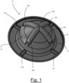
- Fig. 1 provides a perspective view of a preferred embodiment of the device of the present invention constructed from a unitary molded plastic material.
- Supine-deterrent 10 is generally seen to be a hat-shaped device, shaped similar to a campaign hat, sized and configured to be removably placed on the back of the person.
- the device of the present invention serves as a manner of reducing the incidence of snoring while sleeping.
- the structure of supine-deterrent 10 provides just enough of a conscious or subconscious distraction or discomfort as to cause the person to move into a position where such discomfort no longer exists or occurs. In general, this means moving from a position where the person's back is against the relatively firm surface of the sleeping platform (mattress) to a position where such contact is not being made. Further details regarding this functionality are described in conjunction with Figs. 7A and 7B below.
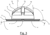
- transitions between perimeter flange 22 and contact annulus 12, as well between contact annulus 12 and the inside of dome base wall 26, include a smooth radius to minimize pressure concentration on the person's skin.
- vent holes may be positioned in other locations such as the peripheral ends of arcuate ridges 18a - 18d or dome top wall 28 .
- a vacuum or suction may be created when the device is adhered to the skin. Such vacuum or suction effect would serve to aid in holding the device in place on a person's skin, in addition to the use of adhesives on the contact area of the device as described in more detail below.
- Adhesive layer 40 represents one of a number of different methods for adhering the supine-deterrent device of the present invention to the back of the person.
- Adhesive layer 40 may preferably be constructed of double-coated medical tape with a medical skin adhesive compound such as that utilized on bandages and the like, that provides sufficient adhesion to prevent movement or removal of the device from the skin unless a specific and direct force is exerted on the device.
- the tape comprises hypoallergenic pressure-sensitive adhesives with a high initial adhesion to a very wide range of substrates.
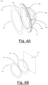
- Figs. 4A and 4B disclose adhesive layer 40.
- Fig. 4A discloses adhesive protective layer 42 which, when removed by peeling from adhesive layer 40, exposes the double-sided medical tape so that a subject can attach supine-deterrent 10 to the subject's back.
- Pull-tab 46 is a flap-like extension on adhesive protective layer 42, providing a grasp point for a person to remove adhesive protective layer 42.
- Fig. 4B provides a perspective view of the sequence of attachment of adhesive protective layer 42, adhesive layer 40 and plastic sheet material 44. During assembly, adhesive layer 40, with the attached adhesive protective layer 42, is applied to the mold of plastic sheet material 44.
- Some appropriate adhesive compounds may provide the ability for re-use of the device with the same adhesive layer without the need for the constant replacement of the adhesive material.
- Some such medical adhesives are known in the art that allow for the temporary removal of a bandage or the like and its replacement after examination of the skin surface beneath the bandage.
- Such adhesive materials may be utilized in conjunction with the device of the present invention, up to a period of re-use where adhesive layer 40 might preferably be replaced.
- Various protective steps may be taken to extend the life of the adhesive material, such as the use of storage sheets that may be placed over the adhesive surface when the device is not in use and removed when the device is to be placed into use.
- the device of the present invention may preferably be manufactured and sold in packages of two with each device re-usable for as many as 5 - 10 days without the need to renew the adhesive. Additional double-sided adhesive foam circular rings may be provided within the package so as to allow the person to renew the adhesive layer and further extend the usable life of the device. Various other methods for renewing the adhesive on the underside of the device are anticipated. Although the device may preferably have a complete circular ring of adhesive on the base, this is not essential and an appropriate level of adhesion may be obtained by a number of adhesive patches spaced about the circular perimeter underside of the device.
- supine-deterrent 10' provides just enough of a conscious or subconscious distraction or discomfort as to cause the person to move into a position where such discomfort no longer exists or occurs. In general, this means moving from a position where the person's back is against the relatively firm surface of the sleeping platform (mattress) to a position where such contact is not being made. Further details regarding this functionality are described in conjunction with Figs. 7A and 7B below.
- Fig. 5 shows in detail the various exterior structural features of supine-deterrent 10' that provide its rigidity, comfort, and ease of positioning and placement for use of the device.
- the overall helmet-shaped configuration of supine-deterrent 10' includes contact edge region 512 which is a relatively flat ring perimeter region that, on an underside surface (not shown), provides the contact point between the device and the skin surface of the person's back. The manner of adhesively attaching the device of the present invention to the person's back is described in more detail below.
- rigidity cross-channels 518 comprise a long cylindrical indentation channel crossed by a short cylindrical indentation channel that together form a cross-shaped recess centered on the apex of reinforced dome region 514 of the device. These rigidity cross-channels 518 primarily provide structural strength to the dome shape of the device.
- Airflow apertures 520 four orthogonally arranged holes in the alternative embodiment shown in Fig. 5 , provide airflow between the interior and exterior of supine-deterrent 10'.
- some airflow between the interior enclosure defined by the device and the open air exterior of the device is desirable in order to prevent the person from sweating and the resultant discomfort that is typically brought about by the absence of any such airflow.
- some alternative embodiments adhere to the skin without such apertures being present in the device. Without the flow of air from the interior of the device to the exterior surroundings, a vacuum or suction effect may be created when the device is adhered to the skin. Such vacuum or suction would serve to aid in holding the device in place on a person's skin, in addition to the use of adhesives on the contact area of the device as previously described.
- Grip indentations 516a and 516b are provided on either side of reinforced dome region 514 and serve both the purpose of providing additional structural rigidity to reinforced dome region 514 and providing an easy means for the person to grasp the device, position it and place it appropriately on the person's back. While the exact placement of the device is not so critical (see discussion below), there is a preference for positioning and placing the device within a region that will most likely encounter the mattress surface when the person turns during sleep into a position that might result in a back-sleeping state. Grip indentations 516a and 516b therefore provide an easy means for handling supine-deterrent 10' while the proper positioning and placement of the device by the person is being carried out.
- Fig. 8 is a top plan view of an alternative device highlighting in greater detail the structures and contours of the various external features of the device as briefly described in conjunction with Fig. 5 .
- supine-deterrent 10' is shown to be constructed from a generally oval-shaped device having contact edge region 512 as well as reinforced dome region 514 as described above.
- Forming contact edge region 512 are perimeter base 822 and perimeter riser 824.
- Forming reinforced dome region 514 are dome base walls 826 and dome top wall 828.
- Rigidity cross-channels 518 are shown as they are positioned and configured within dome top wall 828.
- Rigidity long channel 830 extends partially across the long axis diameter of oval-shaped supine-deterrent 10' while rigidity short channel 832 extends along the short axis diameter of the oval.
- Grip indentations 516a and 516b are shown on either side of dome top wall 828 formed within reinforced dome region 514, primarily within dome base walls 826 and extending to a degree into dome top wall 828.
- Each grip indentation 516a and 516b comprises a grip wall 836a and 836b and a grip base 834a and 834b, respectively.
- These grip indentations 516a and 516b comprising the walls and bases as described, provide the person with the ability to grasp the device using (for example) the thumb of the hand in one of the grip indentations, 516a for example, and the forefinger or two fingers of the same hand in the opposing grip indentation, 516b for example. In this manner the person may slightly squeeze the device to grip it firmly for orientation positioning and placement on the person's back.
- Fig. 9 provides a long axis side elevation view of the alternative device showing in profile the elevational configuration of the device and the various sections of its domed structure as described above.
- Supine-deterrent 10' is seen to comprise contact edge region 512 and reinforced dome region 514.
- Contact edge region 512 is made up of perimeter base 822 and perimeter riser 824.
- Reinforced dome region 514 is made up primarily of dome base walls 826 and dome top wall 828. It is recognized that each of these various regions and sections of the overall helmet-shaped domed structure provide some particular function with regard to rigidity and durability.
- Fig. 9 also discloses from the side view, the configuration of grip indentation 516a with grip base 834a and grip wall 836a. Two of airflow apertures 520 are shown in this view extending across dome top wall 828 to a point where a matched pair of airflow apertures 520 allows for a similar influx and outflow of air from the interior of the device.
- Fig. 9 also discloses adhesive pad 940 positioned on the underside of perimeter base 822 of contact edge region 512.
- Adhesive pad 940 represents one of a number of different methods for adhering the supine-deterrent device of the present invention to the back of the person.
- Adhesive pad 940 may preferably be constructed of a medical skin adhesive compound such as that utilized on bandages and the like, that provides sufficient adhesion to prevent movement or removal of the device from the skin unless a specific and direct force is exerted on the device.
- the device not slide sideways across the skin of the person and remain positioned both in a given location on the person's back and preferably in a given orientation (described in more detail below).
- the character of adhesive pad 940 must, however, be such as to not cause great discomfort in and of itself when the device is removed when the person finally awakes and no longer has need of the device.
- Some appropriate adhesive compounds may provide the ability for re-use of the device with the same adhesive pad without the need for the constant replacement of the adhesive material.
- Some such medical adhesives are known in the art that allow for the temporary removal of a bandage or the like and its replacement after examination of the skin surface beneath the bandage.
- Such adhesive materials may be utilized in conjunction with the device of the present invention, up to a period of re-use where adhesive pad 940 might preferably be replaced.
- Various protective steps may be taken to extend the life of the adhesive material, such as the use of storage sheets that may be placed over the adhesive surface when the device is not in use and removed when the device is to be placed into use.
- the device of the present invention may preferably be manufactured and sold in packages of two with each device re-usable for as many as 5 - 10 days without the need to renew the adhesive. Additional double-sided adhesive foam oval rings may be provided within the package so as to allow the person to renew the adhesive layer and further extend the usable life of the device. Various other methods for renewing the adhesive on the underside of the device are anticipated. Although the device may preferably have a complete oval ring of adhesive on the base, this is not essential and an appropriate level of adhesion may be obtained by a number of adhesive patches spaced about the oval perimeter underside of the device.
- Fig. 10 is a view similar to that shown in Fig. 9 , but oriented orthogonally (90°).
- contact edge region 512 is again shown to comprise perimeter base 822 and perimeter riser 824.
- Reinforced dome region 514 is again shown to comprise dome base walls 826 and dome top wall 828.
- Positioned on dome top wall 828 are rigidity cross-channels 518 with rigidity long channel 830 primarily visible in this view.
- Grip wall edges 836a and 836b of grip indentations 516a and 516b are also seen in this view.
- the view of Fig. 10 shows that the grip indentations 516a and 516b are primarily established near their base and actually extend outward from dome base walls 826 near their top portions. This again provides an appropriately oriented pair of surfaces for the person to grip the device and position it accurately on the person's back. Perhaps even more importantly, these grip surfaces provide an easy means for the person to grasp and remove the device after use.
- Fig. 9 The remaining features discussed with regard to Fig. 9 are likewise shown in Fig. 10 and include airflow apertures 520 as well as adhesive pad 940 positioned on the underside of perimeter base 822.
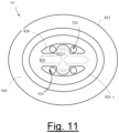
- Fig. 11 is a bottom plan view of the alternative device showing the interior structures of the device. From this view it can be seen that the interior structures do not necessarily directly correspond to the configuration of the exterior features, as if the device were simply a formed and shaped thin-walled structure.
- Supine-deterrent 10' in this view of Fig. 11 is shown to again comprise perimeter base 822 on which is positioned adhesive pad 940. Extending interior to perimeter base 822 are dome base walls 826 which generally do coordinate and correspond with the exterior appearances of these same structures.
- dome top wall 828 reflects a portion of its structure as viewed from the exterior of the device, albeit with fewer contours that reflect variations in the thickness of the walled structure (from dome base walls 826 up to dome top wall 828 ) that are provided, again so as to improve the overall rigidity of the device.
- rigidity long channel 830 is seen as a cylindrical ridge extending into the interior of the device with rigidity short channel 832 likewise forming a crossing ridge to again structure the apex of the device with greater strength.
- Airflow apertures 520 are shown as they extend into the interior of supine-deterrent 10' in order to allow the flow of air from the interior to the exterior ambient air when the device has been placed on the person's back and adhesive pad 940 adheres to the skin of the person's back. Absent airflow apertures 520, adhesive pad 940 would seal off the interior from the exterior ambient air in a way that could confine and contain the natural sweat of the person thereby could cause eventual discomfort and possibly the release of the adhesive material from the person's back.
- Orientation and placement of supine-deterrent 10 on the back of individual 100 is variable based on factors as discussed in more detail below.
- FIG. 7A shows supine-deterrent 10 of the present invention positioned on an individual 54 sleeping on sleep support platform 50 using headrest or pillow 52. Supine-deterrent 10 is preferably placed within a target placement region 56 on the person's back.
- This target region 56 is defined as that area of the person's back where skeletal support would cause contact between the supine-deterrent 10 and sleep support platform 50 in a manner that would be uncomfortable enough to alert the person, consciously or subconsciously, of the need to turn away from a back sleeping position.
- placement of supine-deterrent 10 too far to one side or the other, for example on the shoulders of the person, may not provide enough direct contact between the device and the mattress to give rise to the necessary level of discomfort to deter the person from remaining in the back- sleeping position.
- Fig. 7B shows what would occur when the person turns into a back sleeping position wherein direct contact between supine-deterrent 10 and sleep support platform 50 is made.
- the sleep platform the mattress
- this level of discomfort is sufficient to re-direct the sleep position of the person without necessarily awakening the person for such purpose.
- the subconscious or sleep-conditioning effect of the device is more than sufficient to deter the person from turning to or remaining in a back sleep position for any length of time.
- a person using a device of the present invention may position and adhere the device on the person's back prior to laying down on the sleep surface and falling asleep.
- the device serves to passively deter the individual from moving into a position that puts weight on the dome of the device, such that it can be adhered in a position to passively deter the individual from moving into an undesired position while sleeping.
- adhering the device to corresponding regions of the body this serves to prevent and minimize nocturnal repositioning and/or unintended weight loading of body parts for subjects who need to avoid as much.
- the device of the present invention can be used as a sleep positioner, which when positioned and adhered on a region of a person's body, serves to encourage or discourage particular sleeping postures.
- a sleep positioner which when positioned and adhered on a region of a person's body, serves to encourage or discourage particular sleeping postures.
- alternative uses are also contemplated. For example, experts tend to advise pregnant women not to sleep on their backs later in pregnancy because lying on the back can restrict blood flow.
- the device of the present invention may be used to deter pregnant women from sleeping on their backs which can thereby encourage a side-lying posture in order to maximize blood flow.
- alternative uses for the device can include positioning the device on a region of the body other than the back of a person for reasons other than to deter snoring.
- the device of the present invention may be positioned on the skin in the vicinity of the right hip. When positioned in this manner, the person will be deterred from turning to lie on the site of the injury or surgical procedure thereby preventing possible further damage or injury.
Landscapes
- Health & Medical Sciences (AREA)
- Otolaryngology (AREA)
- Pulmonology (AREA)
- Nursing (AREA)
- Orthopedic Medicine & Surgery (AREA)
- Engineering & Computer Science (AREA)
- Biomedical Technology (AREA)
- Heart & Thoracic Surgery (AREA)
- Vascular Medicine (AREA)
- Life Sciences & Earth Sciences (AREA)
- Animal Behavior & Ethology (AREA)
- General Health & Medical Sciences (AREA)
- Public Health (AREA)
- Veterinary Medicine (AREA)
- Orthopedics, Nursing, And Contraception (AREA)
Claims (14)
- Vorrichtung zum Verhindern einer unerwünschten Schlafhaltung bei menschlichen Subjekten, wobei die Vorrichtung Folgendes umfasst:
einen Herstellungsartikel (10; 10'), wobei der Artikel eine Kuppel (14; 514) aufweist;einen flexiblen Ring (12; 512), der an der Basis der Kuppel positioniert ist, wobei der Ring eine im Wesentlichen ebene untere Oberfläche aufweist, die in der Nähe der Haut eines menschlichen Subjekts in einem Bereich des Körpers eines menschlichen Subjekts positionierbar ist, der ein menschliches Subjekt davon abhält, eine unerwünschte Schlafhaltung beizubehalten, wobei der Ring flexibel ist, um eine Konformität in Bezug auf die Kontur dieser Haut zu ermöglichen; undeinen Kontaktklebstoff (40) auf der im Wesentlichen ebenen unteren Oberfläche (12a) des Rings zum Ankleben des Rings an die Haut eines menschlichen Subjekts in einem Bereich des Körpers eines menschlichen Subjekts, der ein menschliches Subjekt davon abhält, eine unerwünschte Schlafhaltung beizubehalten;wobei die Kuppel eine Höhe aufweist, wobei die Höhe physisches Unbehagen für das menschliche Subjekt durch die nach oben gegen das menschliche Subjekt erzeugte Kraft erzeugt, wenn sich das menschliche Subjekt in der Schlafhaltung mit der nach unten gerichteten Kuppel befindet, dadurch gekennzeichnet, dassdie Kuppel eine Kuppelbasiswand (26; 526), eine Kuppelzwischenwand (30) und eine Kuppeloberwand aufweist, und wobei die Kuppeloberwand (28; 528) einen Scheitelpunkt der Kuppel bildet und wobei die Kuppelzwischenwand konvexer als die Kuppeloberwand ist und einen allgemein glatten Übergang zwischen der Kuppeloberwand und der Kuppelbasiswand bildet. - Vorrichtung nach Anspruch 1, wobei der Gegenstand (10; 10') aus einem Blattmaterial (44) gebildet ist.
- Vorrichtung nach Anspruch 2, wobei der Artikel (10; 10') aus einem elastischen, leichten Kunststoffmaterial geformt ist, das auf einer Stanzpresse aus Folienmaterial aus amorphem Polyethylenterephthalat mit einer Dicke von 0,04445 cm (0,0175 Zoll) gestanzt wird.
- Vorrichtung nach einem der vorhergehenden Ansprüche, wobei die Kuppel (14; 514) eine Form aufweist, die die allgemeine Form eines Kugelabschnitts einschließt.
- Vorrichtung nach einem der vorhergehenden Ansprüche, wobei die Kuppel (14; 514) ferner eine Vielzahl von bogenförmigen Rippen (18a-18d; 518) aufweist, die orthogonal entlang des oberen Teils der äußeren Oberfläche der Kuppel als strukturelle Verstärkung der Kuppel angeordnet sind.
- Vorrichtung nach einem der vorhergehenden Ansprüche, wobei die untere Oberfläche des Rings (12) mehrere Oberflächenaussparungen (19a-19d) aufweist, die von der allgemein ebenen Form dieser unteren Oberfläche abweichen, so dass die Oberflächenaussparungen, wenn sie funktionsfähig auf der Haut eines menschlichen Subjekts in einem Bereich des Körpers eines menschlichen Subjekts positioniert sind, der ein menschliches Subjekt davon abhält, eine unerwünschte Schlafhaltung beizubehalten, dazu neigen, eine Öffnung zu bilden, die Luftstromöffnungen definiert, die einen Luftaustausch zwischen dem Ring und der Haut ermöglichen.
- Vorrichtung nach Anspruch 6, wobei die mehreren Oberflächenaussparungen durch mehrere Oberflächenrippen (19a-19d) ausgebildet werden, die auf der oberen Oberfläche des Rings (12) positioniert sind, und wobei die mehreren Oberflächenrippen den Ring strukturell verstärken.
- Vorrichtung nach einem der vorhergehenden Ansprüche, wobei der Ring (12) ferner einen Flansch (22) aufweist, der oberhalb des Rings an seinem radial äußeren Rand angeordnet ist und sich horizontal über den äußeren Rand des Rings hinaus erstreckt, wobei der Flansch mit dem Ring einstückig ist und einen Vorsprung darstellt, um das Entfernen der Vorrichtung zu erleichtern.
- Vorrichtung nach Anspruch 1, wobei die Kuppel (14; 514) eine Form aufweist, die die allgemeine Form eines eiförmigen Abschnitts einschließt, und wobei die obere Wand der Kuppel eine allgemein eiförmige Form aufweist.
- Vorrichtung nach Anspruch 9, wobei die Kuppeloberwand (528) mindestens zwei Oberflächenaussparungen (830; 832) umfasst, die an dem Scheitelpunkt der Kuppel angeordnet sind, und wobei die mindestens zwei Oberflächenaussparungen eine lange zylindrische (830) Vertiefung umfassen, die entlang der langen Achse der Kuppel angeordnet ist und von einer kurzen zylindrischen Vertiefung (832) gekreuzt wird, die entlang der kurzen Achse der Kuppel angeordnet ist, wobei die Oberflächenaussparungen eine strukturelle Unterstützung für die Kuppel bereitstellen.
- Vorrichtung nach einem der vorhergehenden Ansprüche, wobei die Kuppel (14; 514) ferner mehrere Luftstromöffnungen (360; 520) umfasst, wobei die mehreren Luftstromöffnungen einen ungezwungenen Luftstrom zwischen dem inneren und dem äußeren Bereich der Kuppel und weg von der Haut eines menschlichen Subjekts ermöglichen.
- Vorrichtung nach einem der vorhergehenden Ansprüche, wobei der Kontaktklebstoff (40) ferner ein doppelt beschichtetes medizinisches Klebeband umfasst, wobei das doppelt beschichtete medizinische Klebeband hypoallergene druckempfindliche Klebstoffe mit hoher Anfangshaftung auf einer Vielzahl von Substraten umfasst.
- Vorrichtung nach Anspruch 8, wobei der Kontaktklebstoff (40) ferner eine Klebstoffschutzschicht (42) umfasst, wobei die Klebstoffschutzschicht einen Abziehrücken umfasst.
- Vorrichtung nach Anspruch 1, wobei:der Ring (12) eine im Wesentlichen ebene untere Oberfläche (12a) aufweist, die in der Nähe der Haut eines menschlichen Subjekts auf dem Rücken des menschlichen Subjekts positioniert werden kann, wobei der Ring flexibel ist, um eine Anpassung an die Kontur dieser Haut zu ermöglichen;der Kontaktklebstoff (40) auf der im Wesentlichen ebenen unteren Oberfläche des Ringes zum Ankleben des Ringes an die Haut des Rückens einer menschlichen Person ist;wobei der Artikel (10; 10') aus einem Blattmaterial (44) gebildet ist und der Artikel aus einem elastischen, leichten Kunststoffmaterial geformt ist, das auf einer Stanzpresse aus einem Folienmaterial aus amorphem Polyethylenterephthalat mit einer Dicke von 0,44 mm (0,0175 Zoll) gestanzt wird;wobei die Kuppel eine Form aufweist, die die allgemeine Form eines Kugelabschnitts einschließt, wobei die Kuppel ferner mehrere bogenförmige Rippen (18a-18d) umfasst, die orthogonal entlang des oberen Teils der Außenfläche der Kuppel als strukturelle Verstärkung für die Kuppel angeordnet sind;wobei der Ring (12) mehrere Oberflächenaussparungen (19a-19d) aufweist, die auf der unteren Oberfläche (12a) des Rings angeordnet sind, wobei die mehreren Oberflächenaussparungen von der im Allgemeinen ebenen Form dieser unteren Oberfläche abweichen, so dass sie, wenn sie funktionell auf der Haut des Rückens positioniert sind dazu neigen, eine Öffnung zu bilden, die Luftstromöffnungen definiert, die einen Luftaustausch zwischen dem Ring und der Haut ermöglichen, und wobei die mehreren Oberflächenaussparungen durch mehrere Oberflächenrippen gebildet werden, die auf der oberen Oberfläche des Rings positioniert sind, und wobei die mehreren Oberflächenrippen den Ring strukturell verstärken,wobei der Ring ferner einen Flansch (22) aufweist, der oberhalb des Rings an seinem radial äußeren Rand angeordnet ist und sich horizontal über den äußeren Rand des Rings hinaus erstreckt, wobei der Flansch mit dem Ring einstückig ist und einen Vorsprung darstellt, um das Entfernen der Vorrichtung zu erleichtern; undder Kontaktklebstoff (40) ferner ein doppelt beschichtetes medizinisches Klebeband umfasst, wobei das doppelt beschichtete medizinische Klebeband hypoallergene druckempfindliche Klebstoffe mit hoher Anfangshaftung auf einer Vielzahl von Substraten umfasst und der Kontaktklebstoff ferner eine Klebstoffschutzschicht (42) aufweist, wobei die Klebstoffschutzschicht einen Abziehrücken umfasst;wobei die Kuppel ferner eine Höhe aufweist, wobei die Höhe physisches Unbehagen für das menschliche Subjekt durch die Kraft erzeugt, die nach oben gegen das menschliche Subjekt erzeugt wird, wenn sich das menschliche Subjekt in der Schlafhaltung befindet, wobei die Kuppel nach unten gerichtet ist.
Applications Claiming Priority (4)
| Application Number | Priority Date | Filing Date | Title |
|---|---|---|---|
| US201462002258P | 2014-05-23 | 2014-05-23 | |
| US14/325,473 US10463529B2 (en) | 2012-11-05 | 2014-07-08 | Device and method for deterring back-lying snoring posture |
| EP15795507.1A EP3145456B1 (de) | 2014-05-23 | 2015-05-26 | Vorrichtung zur verhinderung von schnarchen in rückenlage |
| PCT/US2015/032463 WO2015179869A2 (en) | 2014-05-23 | 2015-05-26 | Device & method for deterring back-lying snoring posture |
Related Parent Applications (1)
| Application Number | Title | Priority Date | Filing Date |
|---|---|---|---|
| EP15795507.1A Division EP3145456B1 (de) | 2014-05-23 | 2015-05-26 | Vorrichtung zur verhinderung von schnarchen in rückenlage |
Publications (2)
| Publication Number | Publication Date |
|---|---|
| EP3788993A1 EP3788993A1 (de) | 2021-03-10 |
| EP3788993B1 true EP3788993B1 (de) | 2025-07-02 |
Family
ID=53881143
Family Applications (2)
| Application Number | Title | Priority Date | Filing Date |
|---|---|---|---|
| EP20201479.1A Active EP3788993B1 (de) | 2014-05-23 | 2015-05-26 | Vorrichtung zur verhinderung von schnarchen in rückenlage |
| EP15795507.1A Active EP3145456B1 (de) | 2014-05-23 | 2015-05-26 | Vorrichtung zur verhinderung von schnarchen in rückenlage |
Family Applications After (1)
| Application Number | Title | Priority Date | Filing Date |
|---|---|---|---|
| EP15795507.1A Active EP3145456B1 (de) | 2014-05-23 | 2015-05-26 | Vorrichtung zur verhinderung von schnarchen in rückenlage |
Country Status (8)
| Country | Link |
|---|---|
| US (2) | US10463529B2 (de) |
| EP (2) | EP3788993B1 (de) |
| JP (1) | JP6817816B2 (de) |
| CN (1) | CN106456353A (de) |
| AU (1) | AU2015263906B2 (de) |
| CA (1) | CA2949451C (de) |
| ES (1) | ES3042221T3 (de) |
| WO (1) | WO2015179869A2 (de) |
Families Citing this family (5)
| Publication number | Priority date | Publication date | Assignee | Title |
|---|---|---|---|---|
| WO2015031389A2 (en) | 2013-08-26 | 2015-03-05 | Lightside Md, Llc | Adhesive support devices and methods of making and using them |
| EP3060136A4 (de) * | 2013-10-18 | 2017-06-21 | Lightside Md, Llc | Tragevorrichtungen und verfahren zur herstellung und verwendung davon |
| CN110974238B (zh) * | 2019-11-14 | 2020-11-03 | 北京理工大学 | 用于止鼾床垫的人体睡眠位姿识别和顶推点确定方法及装置 |
| WO2022099110A1 (en) * | 2020-11-06 | 2022-05-12 | Marsco Medical, LLC | Port protector and cover system and method of use |
| US20220233144A1 (en) * | 2021-01-22 | 2022-07-28 | TT1 Products, Inc. | Apparatus and methods for securing sensors |
Family Cites Families (60)
| Publication number | Priority date | Publication date | Assignee | Title |
|---|---|---|---|---|
| US1194200A (en) | 1916-08-08 | Ckockett lowdeb | ||
| US695270A (en) | 1901-12-05 | 1902-03-11 | George M Beringer | Vaccine-shield. |
| US876491A (en) | 1907-08-05 | 1908-01-14 | Carl F Rohwer | Antisnoring device. |
| US898379A (en) | 1908-01-11 | 1908-09-08 | Louis F Liebhardt | Antisnoring device. |
| US2304235A (en) | 1941-06-05 | 1942-12-08 | Edmund R Boots | Sleeping garment |
| US2367690A (en) * | 1943-07-31 | 1945-01-23 | Edgar H Purdy | Wound protector |
| US2952856A (en) | 1956-08-15 | 1960-09-20 | Clarence B Ruff | Adjustable pillow support |
| US3485241A (en) | 1967-11-09 | 1969-12-23 | Robert F L Polley | Infant sleeping garment with posterior posture pad |
| DE2249975A1 (de) | 1972-10-12 | 1974-04-18 | Georg Dipl Ing Vujovic | Antischnarchen - schlafhemd |
| US3924282A (en) | 1974-06-21 | 1975-12-09 | Helen Inez Bond | Therapeutic prop-like support for hemiside reclining persons |
| US4118813A (en) | 1976-11-10 | 1978-10-10 | Armstrong Nolen L | Sleep training pillow for the prevention of snoring |
| US4212296A (en) * | 1978-04-20 | 1980-07-15 | The Kendall Company | Bandage with protective member |
| US4349925A (en) | 1980-03-13 | 1982-09-21 | James K. Macomber | Physiological pillow |
| US4517971A (en) * | 1982-11-22 | 1985-05-21 | Sorbonne Robert L | Guard for venipuncture site and catheter retainer |
| US4744117A (en) | 1984-09-17 | 1988-05-17 | Helen Inez Bond | Prop-like positioning device for hemiside reclining persons |
| JPH01122723U (de) * | 1988-02-12 | 1989-08-21 | ||
| US5144958A (en) * | 1989-06-28 | 1992-09-08 | Mobil Oil Corporation | Apparatus for conducting mammalian dermatological studies |
| US5040546A (en) | 1989-12-21 | 1991-08-20 | Lunar Corporation | Patient positioning device and method |
| CA2039586A1 (en) * | 1990-05-02 | 1991-11-03 | Marian R. Appelt | Crosslinked pressure-sensitive adhesives tolerant of alcohol-based excipients used in transdermal delivery devices and method of preparing same |
| US5036865A (en) | 1990-06-04 | 1991-08-06 | Keaton Powell J | Sleepwear |
| US5165130A (en) | 1992-01-24 | 1992-11-24 | Wendling Helen L | Multipositional infant support system |
| USD352377S (en) | 1993-03-17 | 1994-11-15 | Yury Furman | Vest for discouraging supine posture |
| US5357981A (en) | 1993-07-07 | 1994-10-25 | Zohar Eilam | Apparatus and method for the prevention of snoring |
| US5383475A (en) | 1994-03-14 | 1995-01-24 | Austin; Ronald J. | Snore deterring belt |
| USD362331S (en) | 1994-06-02 | 1995-09-19 | Berger Ii Thomas | Nightshirt |
| US6093160A (en) | 1994-11-21 | 2000-07-25 | Augustine Medical, Inc. | Flexible non-contact wound treatment device |
| USD398139S (en) | 1996-05-06 | 1998-09-15 | Galgon John P | Anti-snoring sleep wear |
| US5752524A (en) | 1997-06-12 | 1998-05-19 | Corcoran; Timothy C. | Device for preventing or reducing snoring |
| US5893365A (en) | 1997-07-28 | 1999-04-13 | Anderson; Clarence D. | Appliance for preventing snoring and obstructive sleep apnea |
| US6357444B1 (en) | 1998-02-18 | 2002-03-19 | Jonathan A. Parker | Motion limiting device |
| US6289893B1 (en) | 1999-08-06 | 2001-09-18 | Harold O. Levitt | Snore reducer jacket |
| SE515754C2 (sv) | 2000-01-27 | 2001-10-08 | Robert Ek | Flyttbar anordning, som hindrar en snarkningsbenägen person att intaga ryggläge samt klädesplagg för användning tillsammans med anordningen |
| US7055526B2 (en) | 2000-08-09 | 2006-06-06 | Mohamed Ali Bakarat | Anti-snoring device comprising a skin compatible adhesive |
| US7134435B2 (en) | 2003-10-22 | 2006-11-14 | Mayo Foundation For Medical Education And Research | Sleeping apparatus and related methods |
| US7483737B2 (en) * | 2003-11-18 | 2009-01-27 | Hisamitsu Pharmaceutical Co., Inc | Electrode chip for biological application and its using method |
| US20050178392A1 (en) | 2004-02-16 | 2005-08-18 | Tinsley Thomas A. | Device to reduce snoring, drooling, and talking while sleeping |
| US6926008B1 (en) * | 2004-04-01 | 2005-08-09 | Harold O. Levitt | Snore relief belt |
| JP3116982U (ja) * | 2004-07-07 | 2006-01-05 | 昭一 新田 | 睡眠時無呼吸対策用用具 |
| US7988673B2 (en) * | 2005-07-14 | 2011-08-02 | Venetec International, Inc. | Protective dressing and methods of use thereof |
| US7469434B2 (en) | 2005-07-15 | 2008-12-30 | Drucker Linda W | Anti-snore sleep positioning method and devices |
| US8356602B2 (en) * | 2006-05-03 | 2013-01-22 | Joseph Crocetti | Devices for treating obstructive sleep apnea and/or snoring |
| EP2032214B1 (de) * | 2006-06-07 | 2017-12-06 | Theravent, Inc. | Nasale schichtvorrichtungen |
| US7999145B2 (en) | 2006-07-05 | 2011-08-16 | Nicolas Kairinos | Orthopaedic pin isolator |
| US8720447B2 (en) | 2006-07-28 | 2014-05-13 | Family Concepts Tjh, Llc | Suspended back pillow for sustaining a side sleeping position |
| US7546651B2 (en) | 2006-12-21 | 2009-06-16 | Back2Sleep Llc | Head and upper neck support device |
| TW200841849A (en) | 2007-04-20 | 2008-11-01 | Ying-Quan He | Multifunctional pillow |
| KR100913350B1 (ko) | 2007-08-06 | 2009-08-20 | 한진규 | 전신 수면자세 보조 장치 |
| US8118030B1 (en) | 2007-10-23 | 2012-02-21 | Bugeja Edward L | Head position control device |
| US8220091B2 (en) | 2008-01-25 | 2012-07-17 | Squire Sleep Systems LLC | Sleep system |
| US20090229618A1 (en) | 2008-03-13 | 2009-09-17 | Serenity And Prosperity Enterprises, Llc | Sleep positioning apparatus |
| EP2161011B2 (de) | 2008-09-03 | 2015-05-20 | Gert Pistor | Wundschutz |
| CN201257046Y (zh) | 2008-09-18 | 2009-06-17 | 高思山 | 畅通气道侧卧仪 |
| US8429775B2 (en) | 2009-06-23 | 2013-04-30 | Vaughn W. North | Suspended back pillow for sustaining a side sleeping position |
| CN201510386U (zh) | 2009-10-18 | 2010-06-23 | 姜文静 | 一种调整睡眠姿势的背心 |
| CN201571511U (zh) | 2009-12-21 | 2010-09-08 | 杨丽莎 | 阻鼾衣服 |
| WO2012009370A2 (en) * | 2010-07-12 | 2012-01-19 | Martin Long Medical Products, Llc | Protective wound shield |
| US20120167895A1 (en) | 2011-01-03 | 2012-07-05 | Sanjiv Tewari | Therapeutic sleep device for discouraging sleeping in a supine position |
| WO2012158586A1 (en) * | 2011-05-17 | 2012-11-22 | Check Todd | Protective bandage device |
| CN202603673U (zh) | 2012-04-10 | 2012-12-19 | 梁文涛 | 睡衣 |
| FR3004922B1 (fr) | 2013-04-27 | 2018-01-26 | Nct Consultants | Dispositif anti-ronflement |
-
2014
- 2014-07-08 US US14/325,473 patent/US10463529B2/en active Active
-
2015
- 2015-05-26 ES ES20201479T patent/ES3042221T3/es active Active
- 2015-05-26 EP EP20201479.1A patent/EP3788993B1/de active Active
- 2015-05-26 EP EP15795507.1A patent/EP3145456B1/de active Active
- 2015-05-26 WO PCT/US2015/032463 patent/WO2015179869A2/en not_active Ceased
- 2015-05-26 CA CA2949451A patent/CA2949451C/en active Active
- 2015-05-26 JP JP2016568827A patent/JP6817816B2/ja active Active
- 2015-05-26 CN CN201580026028.5A patent/CN106456353A/zh active Pending
- 2015-05-26 AU AU2015263906A patent/AU2015263906B2/en active Active
-
2019
- 2019-11-04 US US16/673,568 patent/US11806271B2/en active Active
Also Published As
| Publication number | Publication date |
|---|---|
| ES3042221T3 (en) | 2025-11-19 |
| EP3788993A1 (de) | 2021-03-10 |
| CA2949451A1 (en) | 2015-11-26 |
| US20200129323A1 (en) | 2020-04-30 |
| US11806271B2 (en) | 2023-11-07 |
| JP2017516545A (ja) | 2017-06-22 |
| EP3145456A2 (de) | 2017-03-29 |
| US10463529B2 (en) | 2019-11-05 |
| AU2015263906A1 (en) | 2016-11-24 |
| EP3145456B1 (de) | 2020-10-14 |
| CA2949451C (en) | 2023-08-22 |
| WO2015179869A3 (en) | 2016-04-07 |
| EP3145456A4 (de) | 2018-05-02 |
| JP6817816B2 (ja) | 2021-01-20 |
| AU2015263906B2 (en) | 2019-10-03 |
| WO2015179869A2 (en) | 2015-11-26 |
| CN106456353A (zh) | 2017-02-22 |
| US20150238346A1 (en) | 2015-08-27 |
Similar Documents
| Publication | Publication Date | Title |
|---|---|---|
| US11806271B2 (en) | Device and method for deterring an undesirable sleeping posture | |
| US8356602B2 (en) | Devices for treating obstructive sleep apnea and/or snoring | |
| US20200155396A1 (en) | Method, system, and apparatus for facilitating positioning a person in supine sniff position and providing scapular relief | |
| US5437612A (en) | Antidecubitus immobilization cervical collar | |
| US8006335B1 (en) | Post retinal operation pillow | |
| US5755232A (en) | Universal anatomical support device and method of using same | |
| US20130046219A1 (en) | Neonatal cranial support bonnet | |
| US20180028344A1 (en) | Cervical collar | |
| US20140096777A1 (en) | Sleeping Device to Prevent Snoring | |
| US20120180221A1 (en) | Infant Support Device | |
| JP2016112364A (ja) | 姿勢保持用衣服 | |
| US20050177081A1 (en) | Wrist splint | |
| CN109349719B (zh) | 一种适于颅骨损伤者佩戴的防护帽 | |
| US8555889B2 (en) | Post-surgical protective pillow | |
| JP3136159U (ja) | 男性用採尿器 | |
| KR20220126150A (ko) | 콧구멍 확장기 | |
| JP2003190200A (ja) | いびき防止シール | |
| JP3231369U (ja) | マスク会食用マスク | |
| US20090277464A1 (en) | Gravity Aided Restraint | |
| JP3058977U (ja) | 紙捲り用の手指装着具 | |
| JPWO2003068127A1 (ja) | 男性用採尿器及びこれを用いた採尿方法 |
Legal Events
| Date | Code | Title | Description |
|---|---|---|---|
| PUAI | Public reference made under article 153(3) epc to a published international application that has entered the european phase |
Free format text: ORIGINAL CODE: 0009012 |
|
| STAA | Information on the status of an ep patent application or granted ep patent |
Free format text: STATUS: THE APPLICATION HAS BEEN PUBLISHED |
|
| AC | Divisional application: reference to earlier application |
Ref document number: 3145456 Country of ref document: EP Kind code of ref document: P |
|
| AK | Designated contracting states |
Kind code of ref document: A1 Designated state(s): AL AT BE BG CH CY CZ DE DK EE ES FI FR GB GR HR HU IE IS IT LI LT LU LV MC MK MT NL NO PL PT RO RS SE SI SK SM TR |
|
| STAA | Information on the status of an ep patent application or granted ep patent |
Free format text: STATUS: REQUEST FOR EXAMINATION WAS MADE |
|
| 17P | Request for examination filed |
Effective date: 20210715 |
|
| RBV | Designated contracting states (corrected) |
Designated state(s): AL AT BE BG CH CY CZ DE DK EE ES FI FR GB GR HR HU IE IS IT LI LT LU LV MC MK MT NL NO PL PT RO RS SE SI SK SM TR |
|
| STAA | Information on the status of an ep patent application or granted ep patent |
Free format text: STATUS: EXAMINATION IS IN PROGRESS |
|
| 17Q | First examination report despatched |
Effective date: 20220713 |
|
| GRAP | Despatch of communication of intention to grant a patent |
Free format text: ORIGINAL CODE: EPIDOSNIGR1 |
|
| STAA | Information on the status of an ep patent application or granted ep patent |
Free format text: STATUS: GRANT OF PATENT IS INTENDED |
|
| INTG | Intention to grant announced |
Effective date: 20250103 |
|
| GRAS | Grant fee paid |
Free format text: ORIGINAL CODE: EPIDOSNIGR3 |
|
| GRAA | (expected) grant |
Free format text: ORIGINAL CODE: 0009210 |
|
| STAA | Information on the status of an ep patent application or granted ep patent |
Free format text: STATUS: THE PATENT HAS BEEN GRANTED |
|
| AC | Divisional application: reference to earlier application |
Ref document number: 3145456 Country of ref document: EP Kind code of ref document: P |
|
| AK | Designated contracting states |
Kind code of ref document: B1 Designated state(s): AL AT BE BG CH CY CZ DE DK EE ES FI FR GB GR HR HU IE IS IT LI LT LU LV MC MK MT NL NO PL PT RO RS SE SI SK SM TR |
|
| REG | Reference to a national code |
Ref country code: GB Ref legal event code: FG4D |
|
| REG | Reference to a national code |
Ref country code: CH Ref legal event code: EP |
|
| REG | Reference to a national code |
Ref country code: IE Ref legal event code: FG4D |
|
| REG | Reference to a national code |
Ref country code: DE Ref legal event code: R096 Ref document number: 602015091958 Country of ref document: DE |
|
| REG | Reference to a national code |
Ref country code: NL Ref legal event code: FP |
|
| REG | Reference to a national code |
Ref country code: ES Ref legal event code: FG2A Ref document number: 3042221 Country of ref document: ES Kind code of ref document: T3 Effective date: 20251119 |
|
| PG25 | Lapsed in a contracting state [announced via postgrant information from national office to epo] |
Ref country code: PT Free format text: LAPSE BECAUSE OF FAILURE TO SUBMIT A TRANSLATION OF THE DESCRIPTION OR TO PAY THE FEE WITHIN THE PRESCRIBED TIME-LIMIT Effective date: 20251103 |
|
| REG | Reference to a national code |
Ref country code: AT Ref legal event code: MK05 Ref document number: 1808423 Country of ref document: AT Kind code of ref document: T Effective date: 20250702 |
|
| PG25 | Lapsed in a contracting state [announced via postgrant information from national office to epo] |
Ref country code: IS Free format text: LAPSE BECAUSE OF FAILURE TO SUBMIT A TRANSLATION OF THE DESCRIPTION OR TO PAY THE FEE WITHIN THE PRESCRIBED TIME-LIMIT Effective date: 20251102 |
|
| PG25 | Lapsed in a contracting state [announced via postgrant information from national office to epo] |
Ref country code: NO Free format text: LAPSE BECAUSE OF FAILURE TO SUBMIT A TRANSLATION OF THE DESCRIPTION OR TO PAY THE FEE WITHIN THE PRESCRIBED TIME-LIMIT Effective date: 20251002 |
|
| REG | Reference to a national code |
Ref country code: LT Ref legal event code: MG9D |
|
| PG25 | Lapsed in a contracting state [announced via postgrant information from national office to epo] |
Ref country code: AT Free format text: LAPSE BECAUSE OF FAILURE TO SUBMIT A TRANSLATION OF THE DESCRIPTION OR TO PAY THE FEE WITHIN THE PRESCRIBED TIME-LIMIT Effective date: 20250702 |
|
| PG25 | Lapsed in a contracting state [announced via postgrant information from national office to epo] |
Ref country code: FI Free format text: LAPSE BECAUSE OF FAILURE TO SUBMIT A TRANSLATION OF THE DESCRIPTION OR TO PAY THE FEE WITHIN THE PRESCRIBED TIME-LIMIT Effective date: 20250702 |
|
| PG25 | Lapsed in a contracting state [announced via postgrant information from national office to epo] |
Ref country code: HR Free format text: LAPSE BECAUSE OF FAILURE TO SUBMIT A TRANSLATION OF THE DESCRIPTION OR TO PAY THE FEE WITHIN THE PRESCRIBED TIME-LIMIT Effective date: 20250702 |
|
| PG25 | Lapsed in a contracting state [announced via postgrant information from national office to epo] |
Ref country code: GR Free format text: LAPSE BECAUSE OF FAILURE TO SUBMIT A TRANSLATION OF THE DESCRIPTION OR TO PAY THE FEE WITHIN THE PRESCRIBED TIME-LIMIT Effective date: 20251003 |
|
| PG25 | Lapsed in a contracting state [announced via postgrant information from national office to epo] |
Ref country code: SE Free format text: LAPSE BECAUSE OF FAILURE TO SUBMIT A TRANSLATION OF THE DESCRIPTION OR TO PAY THE FEE WITHIN THE PRESCRIBED TIME-LIMIT Effective date: 20250702 Ref country code: CZ Free format text: LAPSE BECAUSE OF FAILURE TO SUBMIT A TRANSLATION OF THE DESCRIPTION OR TO PAY THE FEE WITHIN THE PRESCRIBED TIME-LIMIT Effective date: 20250702 |
|
| PG25 | Lapsed in a contracting state [announced via postgrant information from national office to epo] |
Ref country code: LV Free format text: LAPSE BECAUSE OF FAILURE TO SUBMIT A TRANSLATION OF THE DESCRIPTION OR TO PAY THE FEE WITHIN THE PRESCRIBED TIME-LIMIT Effective date: 20250702 |
|
| PG25 | Lapsed in a contracting state [announced via postgrant information from national office to epo] |
Ref country code: BG Free format text: LAPSE BECAUSE OF FAILURE TO SUBMIT A TRANSLATION OF THE DESCRIPTION OR TO PAY THE FEE WITHIN THE PRESCRIBED TIME-LIMIT Effective date: 20250702 Ref country code: PL Free format text: LAPSE BECAUSE OF FAILURE TO SUBMIT A TRANSLATION OF THE DESCRIPTION OR TO PAY THE FEE WITHIN THE PRESCRIBED TIME-LIMIT Effective date: 20250702 |
|
| PG25 | Lapsed in a contracting state [announced via postgrant information from national office to epo] |
Ref country code: RS Free format text: LAPSE BECAUSE OF FAILURE TO SUBMIT A TRANSLATION OF THE DESCRIPTION OR TO PAY THE FEE WITHIN THE PRESCRIBED TIME-LIMIT Effective date: 20251002 |
|
| PG25 | Lapsed in a contracting state [announced via postgrant information from national office to epo] |
Ref country code: SM Free format text: LAPSE BECAUSE OF FAILURE TO SUBMIT A TRANSLATION OF THE DESCRIPTION OR TO PAY THE FEE WITHIN THE PRESCRIBED TIME-LIMIT Effective date: 20250702 |
|
| PG25 | Lapsed in a contracting state [announced via postgrant information from national office to epo] |
Ref country code: DK Free format text: LAPSE BECAUSE OF FAILURE TO SUBMIT A TRANSLATION OF THE DESCRIPTION OR TO PAY THE FEE WITHIN THE PRESCRIBED TIME-LIMIT Effective date: 20250702 |