EP3787870B2 - Verfahren zur herstellung eines behälters aus thermoplastischem material durch biaxiale streckung - Google Patents
Verfahren zur herstellung eines behälters aus thermoplastischem material durch biaxiale streckung Download PDFInfo
- Publication number
- EP3787870B2 EP3787870B2 EP19728725.3A EP19728725A EP3787870B2 EP 3787870 B2 EP3787870 B2 EP 3787870B2 EP 19728725 A EP19728725 A EP 19728725A EP 3787870 B2 EP3787870 B2 EP 3787870B2
- Authority
- EP
- European Patent Office
- Prior art keywords
- preform
- pressure
- neck
- axis
- forming
- Prior art date
- Legal status (The legal status is an assumption and is not a legal conclusion. Google has not performed a legal analysis and makes no representation as to the accuracy of the status listed.)
- Active
Links
Images

Classifications
-
- B—PERFORMING OPERATIONS; TRANSPORTING
- B29—WORKING OF PLASTICS; WORKING OF SUBSTANCES IN A PLASTIC STATE IN GENERAL
- B29C—SHAPING OR JOINING OF PLASTICS; SHAPING OF MATERIAL IN A PLASTIC STATE, NOT OTHERWISE PROVIDED FOR; AFTER-TREATMENT OF THE SHAPED PRODUCTS, e.g. REPAIRING
- B29C49/00—Blow-moulding, i.e. blowing a preform or parison to a desired shape within a mould; Apparatus therefor
- B29C49/08—Biaxial stretching during blow-moulding
- B29C49/10—Biaxial stretching during blow-moulding using mechanical means for prestretching
- B29C49/12—Stretching rods
-
- B—PERFORMING OPERATIONS; TRANSPORTING
- B29—WORKING OF PLASTICS; WORKING OF SUBSTANCES IN A PLASTIC STATE IN GENERAL
- B29C—SHAPING OR JOINING OF PLASTICS; SHAPING OF MATERIAL IN A PLASTIC STATE, NOT OTHERWISE PROVIDED FOR; AFTER-TREATMENT OF THE SHAPED PRODUCTS, e.g. REPAIRING
- B29C49/00—Blow-moulding, i.e. blowing a preform or parison to a desired shape within a mould; Apparatus therefor
- B29C49/08—Biaxial stretching during blow-moulding
-
- B—PERFORMING OPERATIONS; TRANSPORTING
- B29—WORKING OF PLASTICS; WORKING OF SUBSTANCES IN A PLASTIC STATE IN GENERAL
- B29C—SHAPING OR JOINING OF PLASTICS; SHAPING OF MATERIAL IN A PLASTIC STATE, NOT OTHERWISE PROVIDED FOR; AFTER-TREATMENT OF THE SHAPED PRODUCTS, e.g. REPAIRING
- B29C49/00—Blow-moulding, i.e. blowing a preform or parison to a desired shape within a mould; Apparatus therefor
- B29C49/42—Component parts, details or accessories; Auxiliary operations
- B29C49/78—Measuring, controlling or regulating
- B29C49/783—Measuring, controlling or regulating blowing pressure
- B29C2049/7834—Pressure increase speed, e.g. dependent on stretch or position
-
- B—PERFORMING OPERATIONS; TRANSPORTING
- B29—WORKING OF PLASTICS; WORKING OF SUBSTANCES IN A PLASTIC STATE IN GENERAL
- B29C—SHAPING OR JOINING OF PLASTICS; SHAPING OF MATERIAL IN A PLASTIC STATE, NOT OTHERWISE PROVIDED FOR; AFTER-TREATMENT OF THE SHAPED PRODUCTS, e.g. REPAIRING
- B29C2949/00—Indexing scheme relating to blow-moulding
- B29C2949/07—Preforms or parisons characterised by their configuration
- B29C2949/0715—Preforms or parisons characterised by their configuration the preform having one end closed
-
- B—PERFORMING OPERATIONS; TRANSPORTING
- B29—WORKING OF PLASTICS; WORKING OF SUBSTANCES IN A PLASTIC STATE IN GENERAL
- B29C—SHAPING OR JOINING OF PLASTICS; SHAPING OF MATERIAL IN A PLASTIC STATE, NOT OTHERWISE PROVIDED FOR; AFTER-TREATMENT OF THE SHAPED PRODUCTS, e.g. REPAIRING
- B29C49/00—Blow-moulding, i.e. blowing a preform or parison to a desired shape within a mould; Apparatus therefor
- B29C49/02—Combined blow-moulding and manufacture of the preform or the parison
- B29C49/06—Injection blow-moulding
-
- B—PERFORMING OPERATIONS; TRANSPORTING
- B29—WORKING OF PLASTICS; WORKING OF SUBSTANCES IN A PLASTIC STATE IN GENERAL
- B29C—SHAPING OR JOINING OF PLASTICS; SHAPING OF MATERIAL IN A PLASTIC STATE, NOT OTHERWISE PROVIDED FOR; AFTER-TREATMENT OF THE SHAPED PRODUCTS, e.g. REPAIRING
- B29C49/00—Blow-moulding, i.e. blowing a preform or parison to a desired shape within a mould; Apparatus therefor
- B29C49/28—Blow-moulding apparatus
- B29C49/30—Blow-moulding apparatus having movable moulds or mould parts
- B29C49/36—Blow-moulding apparatus having movable moulds or mould parts rotatable about one axis
-
- B—PERFORMING OPERATIONS; TRANSPORTING
- B29—WORKING OF PLASTICS; WORKING OF SUBSTANCES IN A PLASTIC STATE IN GENERAL
- B29C—SHAPING OR JOINING OF PLASTICS; SHAPING OF MATERIAL IN A PLASTIC STATE, NOT OTHERWISE PROVIDED FOR; AFTER-TREATMENT OF THE SHAPED PRODUCTS, e.g. REPAIRING
- B29C49/00—Blow-moulding, i.e. blowing a preform or parison to a desired shape within a mould; Apparatus therefor
- B29C49/42—Component parts, details or accessories; Auxiliary operations
- B29C49/4268—Auxiliary operations during the blow-moulding operation
-
- B—PERFORMING OPERATIONS; TRANSPORTING
- B29—WORKING OF PLASTICS; WORKING OF SUBSTANCES IN A PLASTIC STATE IN GENERAL
- B29C—SHAPING OR JOINING OF PLASTICS; SHAPING OF MATERIAL IN A PLASTIC STATE, NOT OTHERWISE PROVIDED FOR; AFTER-TREATMENT OF THE SHAPED PRODUCTS, e.g. REPAIRING
- B29C49/00—Blow-moulding, i.e. blowing a preform or parison to a desired shape within a mould; Apparatus therefor
- B29C49/42—Component parts, details or accessories; Auxiliary operations
- B29C49/58—Blowing means
-
- B—PERFORMING OPERATIONS; TRANSPORTING
- B29—WORKING OF PLASTICS; WORKING OF SUBSTANCES IN A PLASTIC STATE IN GENERAL
- B29K—INDEXING SCHEME ASSOCIATED WITH SUBCLASSES B29B, B29C OR B29D, RELATING TO MOULDING MATERIALS OR TO MATERIALS FOR MOULDS, REINFORCEMENTS, FILLERS OR PREFORMED PARTS, e.g. INSERTS
- B29K2067/00—Use of polyesters or derivatives thereof, as moulding material
- B29K2067/003—PET, i.e. poylethylene terephthalate
-
- B—PERFORMING OPERATIONS; TRANSPORTING
- B29—WORKING OF PLASTICS; WORKING OF SUBSTANCES IN A PLASTIC STATE IN GENERAL
- B29L—INDEXING SCHEME ASSOCIATED WITH SUBCLASS B29C, RELATING TO PARTICULAR ARTICLES
- B29L2031/00—Other particular articles
- B29L2031/712—Containers; Packaging elements or accessories, Packages
- B29L2031/7158—Bottles
Definitions
- thermoplastic material such as polyethylene terephthalate (PET)
- PET polyethylene terephthalate
- a preform has an axisymmetric shape.
- the preform has a neck that already has its final shape, while a body of the preform is intended to be deformed during the forming process.
- the main axis of the preform passes through the center of the neck.
- the bottom of the preform generally has a hemispherical wall centered on the main axis of the preform.
- the body of the preform is heated beyond a glass transition temperature allowing to make the body wall malleable by significantly reducing its elastic limit.
- the neck is kept at a temperature below the glass transition temperature to avoid its deformation.
- the forming method comprises for this purpose a first stretching step during which a sliding stretching rod is introduced coaxially into the neck of the preform until a free end of the stretching rod reaches the bottom of the preform. Then, the stretching rod continues to slide by pushing the bottom of the preform so as to stretch the wall of the body in an axial direction.
- a compressed forming fluid is injected into the body of the preform so as to allow a stretching of the material in a generally circumferential direction of the wall of the body of the preform in order to "inflate” the preform until it reaches its final shape.
- this forming process is carried out in a mold that has an imprint conforming to the final container to be obtained.
- the wall of the body of the preform is pressed against the wall of the imprint under the effect of the pressure of the forming fluid to give the container its final shape.
- preforms are usually obtained by injection of a thermoplastic material. Then, they are cooled and stored for their subsequent transformation into final containers during the forming process.
- thermoplastic material The cooling of the thermoplastic material is controlled so that the material constituting the preform is in an "amorphous" state. This state allows the material to be softened by heating to the glass transition temperature.
- thermoplastic material is carried out through the bottom of the preform, at a point which is arranged on the main axis of the preform. Due to this production method, the bottom of the preform has an injection point which is made of the thermoplastic material in a state which is not very stretchable, even when heated. In addition, this injection point generally has a rough appearance, sometimes extending outward from the external face of the bottom.
- the injection point constitutes a zone of fragility in the wall of the final container. Since the material constituting the injection point does not stretch significantly, it is indeed likely that an accumulation of stretching stresses will form in the vicinity of this injection point at the end of forming.
- the protruding aspect of the injection point relative to the bottom of the container is likely to cause the container to wobble when placed on a flat support.
- the bottom of the final container with a small concave pocket, i.e. one extending towards the inside of the container, at the bottom of which the injection point is arranged.
- the pocket is centered on the main axis of the container. Consequently, in the mold, the imprint of the pocket is arranged in the axis of the drawing rod.
- the injection point For the injection point to be correctly arranged in the pocket of the final container, this assumes that the injection point is substantially located on the main axis of the preform during the forming process.
- This misalignment can be corrected during the drawing step because the free end of the drawing rod has a hemispherical shape that allows the injection point to be realigned with the axis of the preform by sliding the bottom of the preform relative to the rod.
- the drawing rod accumulates heat and its free end becomes hot enough to adhere to the bottom of the preform, no longer allowing the function of realigning the injection point relative to the main axis of the preform to be performed.
- the weight and centrifugal force depend on many factors, such as the rotation speed of the carousel, the weight of the preform or the shape of the preform.
- the injection point cannot be precisely realigned to the preform axis in many cases.
- the injection point injection remains susceptible to being misaligned under the effect of gravity and/or centrifugal force.
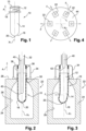
- an axial orientation will be adopted, without limitation, which is indicated by the arrow "A" in the figures and which is parallel to the axis "X1" of the neck 12 of the preform 10.
- Radial directions radiating orthogonally in all directions relative to the axis "X1" of the neck 12 of the preform 10 and finally circumferential directions which extend orthogonally to the axial and radial directions are defined.
- upstream and downstream will be used in reference to the direction of flow of the forming fluid.
- preform 10 made of a thermoplastic material such as polyethylene terephthalate, better known by its acronym "PET".
- PET polyethylene terephthalate
- the preform 10 is for example obtained by injection molding.
- the preform 10 is intended to be transformed into a final container (not shown) during a forming process which will be described in detail later.
- the preform 10 has a general axisymmetric shape with a rectilinear axis "X1".
- the preform 10 comprises an upper neck 12 which has a tubular cylindrical shape with an axis "X1".
- the neck 12 being intended to retain its shape during the forming process, thereafter the main axis "X1" of the preform 10 is defined relative to the neck 12.
- the neck 12 is delimited axially upwards by an annular free edge called a rim 13.
- the neck 12 opens axially downwards into a body 14 which has a tubular cylindrical wall whose axis is normally coaxial with the main vertical axis "X1".
- the body 14 is closed axially downwards by a base 16 of generally hemispherical shape.
- the neck 12 is already molded to its final shape. It is provided on its external face with means for fixing a plug, such as a thread or a groove.
- a radially projecting collar 18 marks the separation between the body 14 and the neck 12. Subsequently, it will be considered that the collar 18 is part of the neck 12.
- the preforms 10 are cooled abruptly, for example by quenching, to give the thermoplastic material an amorphous state. It is thus possible to make the thermoplastic material malleable again by heating beyond a glass transition temperature.
- the term "malleable" means that the elastic limit of the material thus heated is very substantially lower than the elastic limit of said material having a temperature below the glass transition temperature.
- the bottom 16 of the preform 10 has, at its intersection with the axis "X1" of the neck 12 of the preform 10, an injection point 20, corresponding to the injection point of the thermoplastic material during its injection molding. Injection molding techniques do not make it possible to obtain a perfectly amorphous state for the thermoplastic material located at the injection point 20 and its vicinity. The thermoplastic material constituting the injection point 20 and its vicinity is thus in a semi-crystalline state.
- the forming device 22 generally comprises a mold 24 having an internal cavity forming an imprint 26 of the final container to be obtained.
- the mold 24 is delimited upwards by a radial support face 28.
- the imprint 26 opens axially upwards through an orifice 30 opening into the support face 28.
- the body 14 and the bottom 16 of the preform 10 are intended to be received in the cavity while the neck 12 of the preform 10 exits the cavity through the orifice 30, projecting axially above the bearing face 28.
- the preform 10 is generally held in this position by the support of its collar 18 on the bearing face 28, around the periphery of the orifice 30.
- the forming device 22 further comprises a nozzle 32 which is capable of being supplied with forming fluid under pressure and a free lower end of which is intended to be connected to the neck 12 of the preform 10.
- the nozzle 32 is generally mounted to be movable between a position of use in which it is connected to the neck 12 of the preform to allow a forming fluid to be injected under pressure into the preform 10, and a retracted position above the mold 24 in which the nozzle 32 is spaced, generally axially, from the mold 24 to allow the extraction of a finished container or the introduction of a new preform 10.
- the nozzle 32 is intended to be connected to the neck 12 by means of an end bell 34 which covers the neck 12 of the preform when the nozzle occupies its position of use.
- a lower end annular edge of the bell 34 is pressed in a sealed manner against the support face 28, or sometimes on the collar 18, to allow the injection of forming fluid into the preform 10 without damaging the neck 12.
- the nozzle 32 comprises an annular wedge 36, also called a stabilizer, which is mounted to slide axially inside the bell 34 between a high position and a low position towards which it is returned elastically by an elastic member 38 interposed axially between the wedge 36 and the bell 34.
- annular wedge 36 also called a stabilizer
- the wedge 36 comes into contact with the rim 13 of the preform 10 before the nozzle 32 has reached its use position.
- the rim 13 blocks the movement of the wedge 36 which compresses the elastic member 38 in return.
- the forming device 22 further comprises a drawing rod 40 with a main axis coaxial with the axis "X1" of the neck 12 when the preform 10 is housed in the cavity of the mold 24. More generally, the drawing rod 40 is arranged coaxially with the central axis of the orifice 30 of the mold 24. The drawing rod 40 has a free lower end 42. The drawing rod 40 is mounted to slide axially in the nozzle 32 between a retracted position in which its lower end 42 is arranged axially above the neck 12 outside the preform 10, and an extreme lower drawing position in which the lower end 42 is inserted into the preform 10 through the neck 12 to push the bottom 16 of the preform 10 axially close to the bottom of the imprint 26.
- the free end 42 of the drawing rod is thus located inside the preform 10 without being in contact with the bottom 16 of the preform 10, then during a second part of its sliding stroke, the drawing rod 40 effectively pushes the bottom 16 of the preform 10 towards the bottom of the imprint 26 to plastically deform the malleable wall of the preform 10 by axial drawing, as will be explained in more detail later.
- the sliding rod 40 is shown in an intermediate position between its retracted position and its extreme stretched position during the first part of its stroke.
- the body 14 of the preform 10 Prior to its introduction into the mold 24, the body 14 of the preform 10 is made malleable by heating or by maintaining its temperature above a glass transition temperature. Furthermore, the neck 12 already having its final shape is maintained at a temperature below its glass transition temperature so as to remain very significantly more rigid than the body 14.
- the biaxial stretch forming process generally comprises a first stretching step "E1" during which the free end 42 of the stretching rod 40 is inserted coaxially to the axis "X1" into the body 14 of the preform 10 via its neck 12 to the bottom 16 of the preform 10.
- the stretching rod 40 applies a downward axial force against the bottom 16 of the preform 10 to plastically deform the body 14 of the preform 10 by axial stretching.
- a compressed forming fluid is injected at a determined forming pressure "P2" into the preform 10 to stretch the body of the preform 10 mainly circumferentially.
- the forming pressure "P2" is likely to vary between a pre-blowing pressure “P2A” and a blowing pressure “P2B" higher than the pre-blowing pressure "P2A".
- the pre-blowing pressure "P2A” is for example between 2 and 5 bars, while the blowing pressure “P2B” is for example between 14 bars and 40 bars.
- the second step “E2" is for example decomposed into a pre-blowing phase "E2A”, during which the forming fluid is injected at the pre-blowing pressure "P2A”, and into a blowing phase “E2B", during which the forming fluid is injected at the blowing pressure "P2B".
- the pre-blowing phase “E2A” is for example triggered before the end of the first stretching step "E1" while the blowing phase "E2B” is triggered after the end of the first stretching step "E1".
- the malleable body 14 of the preform 10 housed in the mold 24, is subjected to an external bending force "F" which tends to bend the body by radially moving the bottom 16 away from the main axis "X1".
- the body 14 is then likely to bend in the manner of a recessed beam.
- the neck 12, still rigid and firmly held in position by the wedge 36 is similar to the recessed part of the beam, while the bottom 16 of the preform 10 is similar to the free end of the beam.
- the external force "F” is sufficiently intense, the point 20 injection is moved radially relative to the axis “X1” of the neck 12 of the preform 10.
- the external force "F” can be formed by gravitational force and/or by a centrifugal force and/or by a force in reaction to a rectilinear acceleration.
- a carousel 44 is shown rotatably mounted about a vertical axis "X2".
- Several forming devices 22 as described above which are mounted on the periphery of the carousel 44.
- the axes "X1" of the preforms 10 are mounted parallel to the axis "X2" of rotation of the carousel 44.
- the carousel 44 rotates at a constant speed so that the preforms 10 received in the molds 24 of its periphery are subjected to a centrifugal force which here forms the external force "F” which is capable of bending the preforms 10.
- the external force “F” is symbolized by a vector applied to the center of mass of the body 14 of the preform 10.
- the injection point 20 it is preferable for the injection point 20 to be aligned with the axis "X1" of the neck 12. This ensures that the injection point 20 is aligned with the axis of the stretching rod 40. However, this is no longer the case when the body 14 of the preform 10 is bent or poorly positioned in the mold due to centrifugal force. This problem will then cause bottle quality problems, for example with an off-center injection point, or problems with deterioration of the container, for example when the wall of the preform 10 comes into contact with the stretching rod 40 before the end of its elongation, causing local cooling of the wall resulting in tearing of the wall during the blowing operation.
- the invention proposes adding to the forming method a step "E0" of centering the bottom 16 of the preform 10 which is triggered before the free end 42 of the drawing rod 40 is in contact with the bottom 16 of the preform.
- the centering step "E0" is for example triggered before the first stretching step "E1".
- the centering step "E0" is triggered during the first part of the stroke of the drawing rod 40, after or at the same time as the start of the first drawing step "E1".
- the centering step "E0" is triggered during the first part of the stroke of the drawing rod 40, that is to say, before the drawing rod 40 is in contact with the bottom of the preform.
- a forming fluid compressed at a stiffening pressure "P0” is injected into the preform 10.
- the stiffening pressure "P0” is selected so as to center the bottom 16 relative to the axis X1 of the neck 12.
- the person skilled in the art centered the preform in the mold by ensuring the simultaneity of the contacts: of the end of the drawing rod 40 with the bottom of the preform and of the surface of the top of the mold with the surface under the collar. Thanks to these two simultaneous contacts, the person skilled in the art considered that the preform was centered and immobilized before implementing the various steps of the bi-orientation PET forming process.
- the skilled person has only the pre-blowing pressure and the blowing pressure to form a container.
- the pre-blowing pressure has the function of maintaining a space between the stretching rod and the side walls of the preform. In other words, the pre-blowing can only coincide in the context of a longitudinal stretching already initiated by the stretching rod.
- the centering step "E0" comprises a step of introducing compressed fluid at a stiffening pressure "P0" before the end of the drawing rod 40 touches the bottom of the preform.
- the stiffening pressure "P0" is maintained at least until the free end 42 of the drawing rod 40 is in contact with the bottom 16 of the preform 10.
- the preform 10 is then held by the collar 18 at the upper face of the mold and the bottom 16 is kept centered by contact with the drawing rod 40.
- the stiffening pressure "P0" is sufficient to induce tensile stresses in the wall of the body 14 of the preform. Like an inflatable beam, the pressure inside the body 14 of the preform 10 increases the stiffness by bending of the body 14 as a whole.
- the pressure "P0” thus makes it possible to straighten the body 14 of the preform 10 and to maintain the bottom 16, and therefore the injection point 20, substantially axially centered relative to the axis "X1" of the preform 10 despite the application of the external force "F". This effect can easily be observed by injecting air into a balloon at a pressure too low to deform it elastically but which is sufficient to cause the balloon to pass from a flaccid state to a straightened state in which the balloon is sufficiently rigid in bending to defy gravity.
- the pressure "P0" is however chosen to be low enough not to cause the formation of a bubble in the preform 10. Indeed, the preform 10 heated to its glass transition temperature exhibits viscoelastic behavior. It is known to those skilled in the art that applying too high a pressure risks causing the formation of a bubble in the body of the preform, the uncontrolled expansion of which results in the random eccentricity of the bottom 16 of the preform 12.
- the stiffening pressure "P0” can be easily found experimentally by routine tests, for example depending on the properties of the thermoplastic material used and/or depending on the thickness of the wall. Since the external forces likely to be applied to the body 14 of the preform 10 are relatively low, the stiffening pressure "P0” can be very low while being higher than the ambient pressure. For example, for a preform made of PET (polyethylene terephthalate), the stiffening pressure "P0" is less than 1 bar, more particularly the stiffening pressure "P0" is between 1.01 bar and 2 bar. Preferably the stiffening pressure is between 1.05 bar and 1.5 bar.
- a drawing rod 40 is slidably mounted in the nozzle 32.
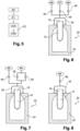
- the forming device 22 comprises a first source 46 of forming fluid compressed to the blowing pressure "P2B" which supplies the blowing nozzle 32, a second source 47 of forming fluid compressed to the pre-blowing pressure "P2A” and a third source 49 of forming fluid compressed to the stiffening pressure "P0".
- Each source 46, 47, 49 of forming fluid is for example produced by the arrangement of a pressure reducer (not shown) associated with a common source (not shown) of fluid compressed to a pressure at least equal to the blowing pressure "P2B", each pressure reducer being designed to relax the forming fluid to the pressure determined for each of the three sources 46, 47, 49 of forming fluid.
- the forming device 22 here comprises three valves 48, 50, 52 which are each associated with one of the three sources 46, 47, 49 and which each control the passage of the forming fluid from the associated source 46, 47, 49, upstream, to the nozzle 32, downstream.
- the first blowing valve 48 is intended to control the injection of forming fluid at the blowing pressure "P2B".
- the first blowing valve 48 is thus interposed between the first source 46 of forming fluid and the nozzle 32.
- the second pre-blowing valve 50 is intended to control the injection of the forming fluid at the pre-blowing pressure "P2A".
- the second pre-blowing valve 50 is thus interposed between the second source 47 of forming fluid and the nozzle 32.
- the third stiffening valve 52 is intended to control the injection of forming fluid at the stiffening pressure "P0" into the nozzle 32.
- the third stiffening valve 52 is thus interposed between the third source 49 of forming fluid and the nozzle 32.
- these three valves 48, 50 and 52 are controlled automatically, for example by an electronic control unit (not shown).
- the pressure of the forming fluid at the source 46 is generally higher than the blowing pressure "P2B" which is itself higher than the pre-blowing pressure "P2A”.
- the stiffening pressure "P0" is still lower than the pre-blowing pressure "P2A”.
- valves 48, 50, 52 are connected directly and in parallel to the common source of forming fluid and they are each provided with means for reducing the pressure of the forming fluid to the required pressure.
- the controlled stiffening valve 52 comprises means for reducing the pressure of the forming fluid distributed by the source 46 to the stiffening pressure "P0" in the nozzle 32.
- Such pressure reduction means are well known and will not be detailed later.
- valve 48, 50, 52 associated with each step and/or phase of the process advantageously makes it possible to reduce the response time of the forming device 22.
- the forming device 22 comprises a second source 54 of forming fluid. compressed to a pressure at least equal to the pre-blowing pressure “P2A” and greater than the stiffening pressure “P0”.
- the controlled stiffening valve 52 is connected between the second source 54 of forming fluid and the nozzle 32 to supply the nozzle 32 with the forming fluid at the stiffening pressure “P0”.
- the second source 54 of forming fluid delivering forming fluid at a pressure higher than the stiffening pressure "P0" means (not shown) for reducing the pressure of the forming fluid to the required stiffening pressure "P0" are arranged between the second source 54 of forming fluid and the stiffening valve 52.
- the pressure reducing means are integrated into the stiffening valve.
- the pre-blowing valve 50 is also arranged between the second source 54 of forming fluid and the nozzle 32, in parallel with the stiffening valve 52.
- the second source 54 of forming fluid advantageously distributes the forming fluid at the pre-blowing pressure such that it is not necessary to arrange pressure reduction means between the second source 54 of forming fluid and the pre-blowing valve 50.
- the second source of forming fluid delivers forming fluid at a pressure higher than the pre-blowing pressure "P2A".
- pressure reduction means are arranged between the second source 54 of forming fluid and the pre-blowing valve 50.
- the pressure reduction means can also be integrated into the pre-blowing valve.
- the blowing valve 48 is here supplied with forming fluid by a first source 46 of forming fluid distinct from the second source 54 of forming fluid.
- the forming device 22 comprises a single source 46 of forming fluid at a pressure greater than or equal to the blowing pressure "P2B".
- the forming device 22 here comprises a single control valve 56 which comprises controlled means for regulating the forming fluid pressure.
- the regulating means are controlled to deliver the forming fluid into the nozzle at a pressure varying at least between the stiffening pressure "P0" and the blowing pressure "P2B" depending on the step of the process at which the preform 10 is located.
- Such regulating means are well known and will not be described in more detail below.
- a fourth embodiment of the forming device 22 is shown. figure 9 , this embodiment of the device being intended to implement the method carried out according to the teachings of the invention but not claimed.
- This fourth embodiment is very similar to the second embodiment shown in the figure 7 .
- the pre-blowing valve 50 and the stiffening valve 52 are replaced by a single control valve 58 which comprises controlled regulating means for the forming fluid pressure.
- the regulating means are controlled to deliver the forming fluid into the nozzle at a pressure varying between the stiffening pressure "P0" and the pre-blowing pressure "P2A" depending on the step of the process at which the preform 10 is located.
- Such regulating means are well known and will not be described in more detail hereinafter.
- the sliding of the drawing rod is controlled as a function of the pressure of the forming fluid contained in the preform.
- the method carried out according to the teachings of the invention advantageously makes it possible to align the injection point 20 of a preform 10 with the axis "X1" of the neck 12 in a simple and inexpensive manner by injecting forming fluid at very low pressure before the drawing rod 40 comes into contact with the bottom 16 of the preform 10.
- the method makes it possible to align the injection point 20 with the axis "X1" of the neck 12, independently of the mass or shape of the preform.
- the method also makes it possible to align the injection point 20 with the axis "X1" of the neck 12 independently of the intensity of the rotation speed of the carousel, whatever the orientation of the axis "X1" of the neck 12 relative to the axis "X2" of rotation of the carousel 44.
Landscapes
- Engineering & Computer Science (AREA)
- Manufacturing & Machinery (AREA)
- Mechanical Engineering (AREA)
- Blow-Moulding Or Thermoforming Of Plastics Or The Like (AREA)
Claims (7)
- Verfahren zur Formung eines Behälters durch Streckblasen eines Vorformlings (10), wobei der achsensymmetrische Vorformling (10) einen röhrenförmigen Körper (14) aufweist, der nach oben hin durch einen Hals (12) mit einer vertikalen Achse (X1) offen ist und nach unten hin durch einen Boden (16) geschlossen ist, wobei der Körper (14) des Vorformlings (10) zuvor durch Erhitzen formbar gemacht wird, wobei das Verfahren Folgendes aufweist:- einen Schritt (E1) des Verstreckens, in dessen Verlauf ein freies Ende (42) einer Reckstange (40) koaxial in den Körper (14) des Vorformlings (10) durch dessen Hals (12) bis zum Boden (16) des Vorformlings (10) eingeführt wird, um den Körper (14) des Vorformlings (10) axial zu verstrecken;- einen Schritt (E2) des Formens, in dessen Verlauf ein komprimiertes Blasfluid mit einem Formungsdruck (P2) in den Vorformling (10) eingeblasen wird;dadurch gekennzeichnet, dass es einen Schritt (E0) des Zentrierens des Bodens (16) des Vorformlings aufweist, der ausgelöst wird, bevor das freie Ende (42) der Reckstange (40) mit dem Boden (16) des Vorformlings (10) in Kontakt steht, und in dessen Verlauf ein Formungsfluid, das auf einen Versteifungsdruck (P0) komprimiert ist, in den Vorformling (10) eingeblasen wird, um den Boden (16) des Vorformlings (10) bezogen auf die Achse "X1" des Halses (12) zu zentrieren, wobei der Versteifungsdruck (P0) wenigstens beibehalten wird, bis das freie Ende (42) der Reckstange (40) mit dem Boden (16) des Vorformlings (10) in Kontakt steht.
- Verfahren nach dem vorhergehenden Anspruch, dadurch gekennzeichnet, dass der Versteifungsdruck (P0) zwischen 1,01 bar und 2 bar, vorzugsweise zwischen 1,05 bar und 1,5 bar beträgt.
- Verfahren nach einem der vorhergehenden Ansprüche, dadurch gekennzeichnet, dass im Verlauf des Formungsverfahrens der Hals (12) des Vorformlings (10) bezogen auf eine Auflagefläche (28) festgehalten wird.
- Verfahren nach einem der vorhergehenden Ansprüche, dadurch gekennzeichnet, dass der Vorformling (10) einer äußeren Biegekraft (F) ausgesetzt wird, die bestrebt ist, den Körper zu biegen, indem der Boden (16) von der Achse (X1) des Halses (12) radial entfernt wird, wobei der Versteifungsdruck (P0) die Biegesteifigkeit des Körpers (14) des Vorformlings (10) erhöht, damit der Boden (16) bezogen auf die Achse (X1) des Halses (12) im Wesentlichen axial zentriert bleibt.
- Verfahren nach dem vorhergehenden Anspruch, dadurch gekennzeichnet, dass der Vorformling in eine Form (24) eingeführt wird, die am Umfang eines Karussells (44) montiert ist, das sich um eine Achse (X2) dreht, wobei die Biegekraft (F) von einer Fliehkraft gebildet wird, die bei der Drehung des Karussells (44) auf den Körper (14) des Vorformlings (10) wirkt.
- Verfahren nach dem vorhergehenden Anspruch, dadurch gekennzeichnet, dass der Vorformling (10) so auf dem Karussell (44) angeordnet ist, dass die Achse (X1) seines Halses (12) im Wesentlichen parallel zur Drehachse (X2) des Karussells (44) verläuft.
- Verfahren nach einem der vorhergehenden Ansprüche, dadurch gekennzeichnet, dass im Verlauf des Schritts (E2) des Blasens der Formungsdruck (P2) zwischen einem Vorblasdruck (P2A) und einem Blasdruck (P2B), der höher als der Vorblasdruck (P2A) ist, variieren kann.
Applications Claiming Priority (2)
| Application Number | Priority Date | Filing Date | Title |
|---|---|---|---|
| FR1853771A FR3080795B1 (fr) | 2018-05-02 | 2018-05-02 | Procede de formage de recipient en materiau thermoplastique par etirage bi-axial |
| PCT/FR2019/051003 WO2019211557A1 (fr) | 2018-05-02 | 2019-04-30 | Procédé de formage de récipient en matériau thermoplastique par étirage bi-axial |
Publications (3)
| Publication Number | Publication Date |
|---|---|
| EP3787870A1 EP3787870A1 (de) | 2021-03-10 |
| EP3787870B1 EP3787870B1 (de) | 2022-03-16 |
| EP3787870B2 true EP3787870B2 (de) | 2025-01-08 |
Family
ID=63683974
Family Applications (1)
| Application Number | Title | Priority Date | Filing Date |
|---|---|---|---|
| EP19728725.3A Active EP3787870B2 (de) | 2018-05-02 | 2019-04-30 | Verfahren zur herstellung eines behälters aus thermoplastischem material durch biaxiale streckung |
Country Status (3)
| Country | Link |
|---|---|
| EP (1) | EP3787870B2 (de) |
| FR (1) | FR3080795B1 (de) |
| WO (1) | WO2019211557A1 (de) |
Families Citing this family (1)
| Publication number | Priority date | Publication date | Assignee | Title |
|---|---|---|---|---|
| FR3103131B1 (fr) * | 2019-11-20 | 2021-11-05 | Sidel Participations | "Procédé d'orientation d'une préforme dans un moule" |
Citations (10)
| Publication number | Priority date | Publication date | Assignee | Title |
|---|---|---|---|---|
| US4009310A (en) † | 1976-07-01 | 1977-02-22 | The General Tire & Rubber Company | Method of improving adhesion of secondary backings on carpets |
| US4904736A (en) † | 1987-06-16 | 1990-02-27 | Denki Kagaku Kogyo Kabushiki Kaisha | Acrylic rubber composition |
| EP0795580A1 (de) † | 1994-11-30 | 1997-09-17 | Nippon Zeon Co., Ltd. | Vulkanisierbare kautschukzusammensetzung, dichtung zur verwendung im dynamischen zustand und werkstoff dafür |
| EP0796890A1 (de) † | 1996-03-18 | 1997-09-24 | ENICHEM S.p.A. | Vulkanisierbare Acrylatkautschukzusammensetzung |
| US6274662B1 (en) † | 1999-04-09 | 2001-08-14 | J.M. Huber Corporation | Vulcanizable elastomeric compositions containing surface treated barium sulfate and vulcanizates thereof |
| WO2002002864A1 (en) † | 2000-06-30 | 2002-01-10 | Basf Corporation | Carpet backing adhesive and its use in recyclable carpet |
| US6359076B1 (en) † | 1998-12-09 | 2002-03-19 | National Starch And Chemical Investment Holding Corporation | Crosslinkable carpet-back coating with hydroxy-functionalized vinyl acetate emulsion polymers |
| WO2008023075A1 (de) † | 2006-08-25 | 2008-02-28 | Sachtleben Chemie Gmbh | Bariumsulfat enthaltendes komposit |
| WO2008054614A1 (en) † | 2006-10-31 | 2008-05-08 | Dow Global Technologies Inc. | Carpet backing composition |
| US20140346707A1 (en) † | 2012-01-12 | 2014-11-27 | Daikin Industries, Ltd. | Acrylic rubber composition, acrylic rubber molded product, and method for producing same |
Family Cites Families (11)
| Publication number | Priority date | Publication date | Assignee | Title |
|---|---|---|---|---|
| JP2556246B2 (ja) * | 1992-12-08 | 1996-11-20 | 東洋製罐株式会社 | 耐熱性ポリエステル容器及びその製法 |
| US6428735B1 (en) | 1999-02-26 | 2002-08-06 | Schmalbach-Lubeca Ag | Method for making a carbonated soft drink bottle with an internal web and hand-grip feature |
| FR2798093B1 (fr) | 1999-09-03 | 2001-11-30 | Sidel Sa | Machine rotative d'etirage-soufflage comportant une commande magnetique de la tige d'etirage |
| US6855289B2 (en) * | 2001-11-27 | 2005-02-15 | Graham Packaging Pet Technologies, Inc. | Method and apparatus for cooling during in-mold handle attachment |
| DE202004021780U1 (de) | 2004-03-25 | 2010-12-09 | Krones Ag | Vorrichtung zum Herstellen eines insbesondere wärmebeständigen Hohlkörpers |
| DE102009060654B4 (de) | 2009-12-22 | 2019-05-16 | Krones Aktiengesellschaft | Verfahren und Vorrichtung zum Herstellen von Kunststoffflaschen |
| DE102010035496A1 (de) | 2010-08-25 | 2012-03-01 | Krones Aktiengesellschaft | Fördervorrichtung zum Fördern von Vorformlingen |
| DE102011015666B4 (de) * | 2011-03-31 | 2017-03-23 | Khs Corpoplast Gmbh | Verfahren sowie Vorrichtung zur Herstellung von Behältern |
| FR2975331B1 (fr) * | 2011-05-19 | 2014-03-07 | Sidel Participations | Procede d'etirage soufflage d'un recipient, comprenant une retraction de la tige d'etirage au cours d'une operation de boxage |
| WO2013135838A1 (en) | 2012-03-14 | 2013-09-19 | Norgren Gmbh | Stretch blow molding system with a proportional pre-blowing valve |
| GB2531571A (en) | 2014-10-22 | 2016-04-27 | Univ Belfast | Stretch blow moulding apparatus and method |
-
2018
- 2018-05-02 FR FR1853771A patent/FR3080795B1/fr not_active Expired - Fee Related
-
2019
- 2019-04-30 WO PCT/FR2019/051003 patent/WO2019211557A1/fr not_active Ceased
- 2019-04-30 EP EP19728725.3A patent/EP3787870B2/de active Active
Patent Citations (11)
| Publication number | Priority date | Publication date | Assignee | Title |
|---|---|---|---|---|
| US4009310A (en) † | 1976-07-01 | 1977-02-22 | The General Tire & Rubber Company | Method of improving adhesion of secondary backings on carpets |
| US4904736A (en) † | 1987-06-16 | 1990-02-27 | Denki Kagaku Kogyo Kabushiki Kaisha | Acrylic rubber composition |
| EP0795580A1 (de) † | 1994-11-30 | 1997-09-17 | Nippon Zeon Co., Ltd. | Vulkanisierbare kautschukzusammensetzung, dichtung zur verwendung im dynamischen zustand und werkstoff dafür |
| EP0796890A1 (de) † | 1996-03-18 | 1997-09-24 | ENICHEM S.p.A. | Vulkanisierbare Acrylatkautschukzusammensetzung |
| US6359076B1 (en) † | 1998-12-09 | 2002-03-19 | National Starch And Chemical Investment Holding Corporation | Crosslinkable carpet-back coating with hydroxy-functionalized vinyl acetate emulsion polymers |
| US6274662B1 (en) † | 1999-04-09 | 2001-08-14 | J.M. Huber Corporation | Vulcanizable elastomeric compositions containing surface treated barium sulfate and vulcanizates thereof |
| WO2002002864A1 (en) † | 2000-06-30 | 2002-01-10 | Basf Corporation | Carpet backing adhesive and its use in recyclable carpet |
| WO2008023075A1 (de) † | 2006-08-25 | 2008-02-28 | Sachtleben Chemie Gmbh | Bariumsulfat enthaltendes komposit |
| US20090318594A1 (en) † | 2006-08-25 | 2009-12-24 | Sachtleben Chemie Gmbh | Barium sulfate-containing composite |
| WO2008054614A1 (en) † | 2006-10-31 | 2008-05-08 | Dow Global Technologies Inc. | Carpet backing composition |
| US20140346707A1 (en) † | 2012-01-12 | 2014-11-27 | Daikin Industries, Ltd. | Acrylic rubber composition, acrylic rubber molded product, and method for producing same |
Non-Patent Citations (4)
| Title |
|---|
| Gooch Jan W.: Encyclopedic Dictionary of Polymers, 2nd Edition, Springer Verlag, 2011, Page 15XP NUMBER: SOURCE: () † |
| R.B. Simpson, RUBBER BASICS, Rapra Technologies Ltd.. 2002, pages 94-95XP NUMBER: SOURCE: () † |
| Standard Practice for Rubber and Rubber Latices - Nomenclature, ASTM, Designation D1418 - 17, 2019XP NUMBER: SOURCE: () † |
| T. Whelan, POLYMER TECHNOLOGY DICTIONARY, Chapman & Hall. 1994, pages 13-14 XP NUMBER: SOURCE: † |
Also Published As
| Publication number | Publication date |
|---|---|
| FR3080795B1 (fr) | 2020-04-03 |
| EP3787870B1 (de) | 2022-03-16 |
| EP3787870A1 (de) | 2021-03-10 |
| WO2019211557A1 (fr) | 2019-11-07 |
| FR3080795A1 (fr) | 2019-11-08 |
Similar Documents
| Publication | Publication Date | Title |
|---|---|---|
| WO2004065105A1 (fr) | Procede et installation de fabrication d'un recipient en matiere plastique | |
| EP1880825B1 (de) | Vorrichtung zur individuellen Halterung eines Behälters, der mit einem Hals versehen ist, und Anlage, die mit Fördervorrichtungen mit einer solchen Halterungsvorrichtung versehen ist | |
| EP1324870A1 (de) | Streckblasmaschine mit einer bewegung angetrieben von dem streckhelfer | |
| EP3439849B1 (de) | Verfahren zur bevorzugten erwärmung eines hohlkörpers mit einem markierungsschritt | |
| EP0059016B1 (de) | Thermoplastische Vorform und Verfahren zum Blasformen eines Hohlkörpers aus einer derartigen Vorform | |
| FR3045446A1 (fr) | Indexation angulaire d'une preforme chauffee non uniformement par mesure de temperature | |
| EP3105034B1 (de) | Formeinheit zur herstellung von behältern aus vorformlingen aus kunststoffmaterial | |
| EP1216197B1 (de) | Transportvorrichtung für vorformlinge in eine vorrichtung zur herstellung von behältern durch blasformen | |
| EP3787870B2 (de) | Verfahren zur herstellung eines behälters aus thermoplastischem material durch biaxiale streckung | |
| FR2766406A1 (fr) | Procede et installation de fabrication de recipients par soufflage d'ebauches en materiau thermoplastique | |
| FR2882963A1 (fr) | Dispositif de transport d'une preforme dans un four, tournette et machine de conditionnement thermique pour installation de soufflage de recipients en materiau thermoplastique comprenant un tel dispositif | |
| EP0000801A1 (de) | Verfahren zur Herstellung orientierter Hohlkörper | |
| EP3131734B1 (de) | Giesseinheit mit formbodenbetätigungseinrichtung auf einer fixen halterung | |
| EP1912776A1 (de) | Blasanlage mit einer düse mit einer lippendichtung | |
| EP3173212B1 (de) | Verfahren zur steuerung einer spritzguss-einheit | |
| FR2874193A1 (fr) | Machine de souflage pour la fabrication de recipients thermoplastiques et installation de fabrication de recipients incorporant une telle machine | |
| EP3055119B1 (de) | Vorrichtung zum greifen eines behälters mit einer nase, in der expansionsbacken in umfangsposition gehalten werden | |
| EP3846990B1 (de) | Vorform für behälter aus kunststoff | |
| EP4261007B1 (de) | Streckstange zur herstellung von behältern | |
| WO2009103927A2 (fr) | Procédé et dispositif de fabrication d'un récipient en matière plastique par soufflage | |
| EP0008481A1 (de) | Vorrichtung zum Warmstrecken von Vorformlingen aus thermoplastischem Kunststoff beim Blasformen | |
| EP4261006A1 (de) | Zieh- und kühlstab zur herstellung von behältern | |
| EP4061609B1 (de) | Verfahren zum ausrichten einer vorform in einer gussform | |
| EP3883743B1 (de) | Verfahren zur herstellung eines kunststoffbehälters mit einem unter verwendung von verpackungstechnik hergestellten griff | |
| FR3050137A1 (fr) | Tige d'etirage pour un ensemble de formage d'un recipient, unite et ensemble de formage pourvus d'une telle tige |
Legal Events
| Date | Code | Title | Description |
|---|---|---|---|
| STAA | Information on the status of an ep patent application or granted ep patent |
Free format text: STATUS: UNKNOWN |
|
| STAA | Information on the status of an ep patent application or granted ep patent |
Free format text: STATUS: THE INTERNATIONAL PUBLICATION HAS BEEN MADE |
|
| PUAI | Public reference made under article 153(3) epc to a published international application that has entered the european phase |
Free format text: ORIGINAL CODE: 0009012 |
|
| STAA | Information on the status of an ep patent application or granted ep patent |
Free format text: STATUS: REQUEST FOR EXAMINATION WAS MADE |
|
| 17P | Request for examination filed |
Effective date: 20201110 |
|
| AK | Designated contracting states |
Kind code of ref document: A1 Designated state(s): AL AT BE BG CH CY CZ DE DK EE ES FI FR GB GR HR HU IE IS IT LI LT LU LV MC MK MT NL NO PL PT RO RS SE SI SK SM TR |
|
| AX | Request for extension of the european patent |
Extension state: BA ME |
|
| TPAC | Observations filed by third parties |
Free format text: ORIGINAL CODE: EPIDOSNTIPA |
|
| DAV | Request for validation of the european patent (deleted) | ||
| DAX | Request for extension of the european patent (deleted) | ||
| GRAP | Despatch of communication of intention to grant a patent |
Free format text: ORIGINAL CODE: EPIDOSNIGR1 |
|
| STAA | Information on the status of an ep patent application or granted ep patent |
Free format text: STATUS: GRANT OF PATENT IS INTENDED |
|
| GRAJ | Information related to disapproval of communication of intention to grant by the applicant or resumption of examination proceedings by the epo deleted |
Free format text: ORIGINAL CODE: EPIDOSDIGR1 |
|
| GRAP | Despatch of communication of intention to grant a patent |
Free format text: ORIGINAL CODE: EPIDOSNIGR1 |
|
| INTG | Intention to grant announced |
Effective date: 20211014 |
|
| INTG | Intention to grant announced |
Effective date: 20211027 |
|
| GRAS | Grant fee paid |
Free format text: ORIGINAL CODE: EPIDOSNIGR3 |
|
| GRAA | (expected) grant |
Free format text: ORIGINAL CODE: 0009210 |
|
| STAA | Information on the status of an ep patent application or granted ep patent |
Free format text: STATUS: THE PATENT HAS BEEN GRANTED |
|
| AK | Designated contracting states |
Kind code of ref document: B1 Designated state(s): AL AT BE BG CH CY CZ DE DK EE ES FI FR GB GR HR HU IE IS IT LI LT LU LV MC MK MT NL NO PL PT RO RS SE SI SK SM TR |
|
| REG | Reference to a national code |
Ref country code: GB Ref legal event code: FG4D Free format text: NOT ENGLISH |
|
| REG | Reference to a national code |
Ref country code: CH Ref legal event code: EP Ref country code: DE Ref legal event code: R096 Ref document number: 602019012646 Country of ref document: DE |
|
| REG | Reference to a national code |
Ref country code: IE Ref legal event code: FG4D Free format text: LANGUAGE OF EP DOCUMENT: FRENCH |
|
| REG | Reference to a national code |
Ref country code: AT Ref legal event code: REF Ref document number: 1475585 Country of ref document: AT Kind code of ref document: T Effective date: 20220415 |
|
| REG | Reference to a national code |
Ref country code: LT Ref legal event code: MG9D |
|
| REG | Reference to a national code |
Ref country code: NL Ref legal event code: MP Effective date: 20220316 |
|
| PG25 | Lapsed in a contracting state [announced via postgrant information from national office to epo] |
Ref country code: SE Free format text: LAPSE BECAUSE OF FAILURE TO SUBMIT A TRANSLATION OF THE DESCRIPTION OR TO PAY THE FEE WITHIN THE PRESCRIBED TIME-LIMIT Effective date: 20220316 Ref country code: RS Free format text: LAPSE BECAUSE OF FAILURE TO SUBMIT A TRANSLATION OF THE DESCRIPTION OR TO PAY THE FEE WITHIN THE PRESCRIBED TIME-LIMIT Effective date: 20220316 Ref country code: NO Free format text: LAPSE BECAUSE OF FAILURE TO SUBMIT A TRANSLATION OF THE DESCRIPTION OR TO PAY THE FEE WITHIN THE PRESCRIBED TIME-LIMIT Effective date: 20220616 Ref country code: LT Free format text: LAPSE BECAUSE OF FAILURE TO SUBMIT A TRANSLATION OF THE DESCRIPTION OR TO PAY THE FEE WITHIN THE PRESCRIBED TIME-LIMIT Effective date: 20220316 Ref country code: HR Free format text: LAPSE BECAUSE OF FAILURE TO SUBMIT A TRANSLATION OF THE DESCRIPTION OR TO PAY THE FEE WITHIN THE PRESCRIBED TIME-LIMIT Effective date: 20220316 Ref country code: BG Free format text: LAPSE BECAUSE OF FAILURE TO SUBMIT A TRANSLATION OF THE DESCRIPTION OR TO PAY THE FEE WITHIN THE PRESCRIBED TIME-LIMIT Effective date: 20220616 |
|
| REG | Reference to a national code |
Ref country code: AT Ref legal event code: MK05 Ref document number: 1475585 Country of ref document: AT Kind code of ref document: T Effective date: 20220316 |
|
| PG25 | Lapsed in a contracting state [announced via postgrant information from national office to epo] |
Ref country code: LV Free format text: LAPSE BECAUSE OF FAILURE TO SUBMIT A TRANSLATION OF THE DESCRIPTION OR TO PAY THE FEE WITHIN THE PRESCRIBED TIME-LIMIT Effective date: 20220316 Ref country code: GR Free format text: LAPSE BECAUSE OF FAILURE TO SUBMIT A TRANSLATION OF THE DESCRIPTION OR TO PAY THE FEE WITHIN THE PRESCRIBED TIME-LIMIT Effective date: 20220617 Ref country code: FI Free format text: LAPSE BECAUSE OF FAILURE TO SUBMIT A TRANSLATION OF THE DESCRIPTION OR TO PAY THE FEE WITHIN THE PRESCRIBED TIME-LIMIT Effective date: 20220316 |
|
| PG25 | Lapsed in a contracting state [announced via postgrant information from national office to epo] |
Ref country code: NL Free format text: LAPSE BECAUSE OF FAILURE TO SUBMIT A TRANSLATION OF THE DESCRIPTION OR TO PAY THE FEE WITHIN THE PRESCRIBED TIME-LIMIT Effective date: 20220316 |
|
| PG25 | Lapsed in a contracting state [announced via postgrant information from national office to epo] |
Ref country code: SM Free format text: LAPSE BECAUSE OF FAILURE TO SUBMIT A TRANSLATION OF THE DESCRIPTION OR TO PAY THE FEE WITHIN THE PRESCRIBED TIME-LIMIT Effective date: 20220316 Ref country code: SK Free format text: LAPSE BECAUSE OF FAILURE TO SUBMIT A TRANSLATION OF THE DESCRIPTION OR TO PAY THE FEE WITHIN THE PRESCRIBED TIME-LIMIT Effective date: 20220316 Ref country code: RO Free format text: LAPSE BECAUSE OF FAILURE TO SUBMIT A TRANSLATION OF THE DESCRIPTION OR TO PAY THE FEE WITHIN THE PRESCRIBED TIME-LIMIT Effective date: 20220316 Ref country code: PT Free format text: LAPSE BECAUSE OF FAILURE TO SUBMIT A TRANSLATION OF THE DESCRIPTION OR TO PAY THE FEE WITHIN THE PRESCRIBED TIME-LIMIT Effective date: 20220718 Ref country code: ES Free format text: LAPSE BECAUSE OF FAILURE TO SUBMIT A TRANSLATION OF THE DESCRIPTION OR TO PAY THE FEE WITHIN THE PRESCRIBED TIME-LIMIT Effective date: 20220316 Ref country code: EE Free format text: LAPSE BECAUSE OF FAILURE TO SUBMIT A TRANSLATION OF THE DESCRIPTION OR TO PAY THE FEE WITHIN THE PRESCRIBED TIME-LIMIT Effective date: 20220316 Ref country code: CZ Free format text: LAPSE BECAUSE OF FAILURE TO SUBMIT A TRANSLATION OF THE DESCRIPTION OR TO PAY THE FEE WITHIN THE PRESCRIBED TIME-LIMIT Effective date: 20220316 Ref country code: AT Free format text: LAPSE BECAUSE OF FAILURE TO SUBMIT A TRANSLATION OF THE DESCRIPTION OR TO PAY THE FEE WITHIN THE PRESCRIBED TIME-LIMIT Effective date: 20220316 |
|
| PG25 | Lapsed in a contracting state [announced via postgrant information from national office to epo] |
Ref country code: PL Free format text: LAPSE BECAUSE OF FAILURE TO SUBMIT A TRANSLATION OF THE DESCRIPTION OR TO PAY THE FEE WITHIN THE PRESCRIBED TIME-LIMIT Effective date: 20220316 Ref country code: IS Free format text: LAPSE BECAUSE OF FAILURE TO SUBMIT A TRANSLATION OF THE DESCRIPTION OR TO PAY THE FEE WITHIN THE PRESCRIBED TIME-LIMIT Effective date: 20220716 Ref country code: AL Free format text: LAPSE BECAUSE OF FAILURE TO SUBMIT A TRANSLATION OF THE DESCRIPTION OR TO PAY THE FEE WITHIN THE PRESCRIBED TIME-LIMIT Effective date: 20220316 |
|
| REG | Reference to a national code |
Ref country code: CH Ref legal event code: PL |
|
| REG | Reference to a national code |
Ref country code: DE Ref legal event code: R026 Ref document number: 602019012646 Country of ref document: DE |
|
| PLBI | Opposition filed |
Free format text: ORIGINAL CODE: 0009260 |
|
| REG | Reference to a national code |
Ref country code: BE Ref legal event code: MM Effective date: 20220430 |
|
| PLAX | Notice of opposition and request to file observation + time limit sent |
Free format text: ORIGINAL CODE: EPIDOSNOBS2 |
|
| 26 | Opposition filed |
Opponent name: KRONES AG Effective date: 20221215 |
|
| PG25 | Lapsed in a contracting state [announced via postgrant information from national office to epo] |
Ref country code: MC Free format text: LAPSE BECAUSE OF FAILURE TO SUBMIT A TRANSLATION OF THE DESCRIPTION OR TO PAY THE FEE WITHIN THE PRESCRIBED TIME-LIMIT Effective date: 20220316 Ref country code: LU Free format text: LAPSE BECAUSE OF NON-PAYMENT OF DUE FEES Effective date: 20220430 Ref country code: LI Free format text: LAPSE BECAUSE OF NON-PAYMENT OF DUE FEES Effective date: 20220430 Ref country code: DK Free format text: LAPSE BECAUSE OF FAILURE TO SUBMIT A TRANSLATION OF THE DESCRIPTION OR TO PAY THE FEE WITHIN THE PRESCRIBED TIME-LIMIT Effective date: 20220316 Ref country code: CH Free format text: LAPSE BECAUSE OF NON-PAYMENT OF DUE FEES Effective date: 20220430 |
|
| PG25 | Lapsed in a contracting state [announced via postgrant information from national office to epo] |
Ref country code: SI Free format text: LAPSE BECAUSE OF FAILURE TO SUBMIT A TRANSLATION OF THE DESCRIPTION OR TO PAY THE FEE WITHIN THE PRESCRIBED TIME-LIMIT Effective date: 20220316 Ref country code: BE Free format text: LAPSE BECAUSE OF NON-PAYMENT OF DUE FEES Effective date: 20220430 |
|
| PG25 | Lapsed in a contracting state [announced via postgrant information from national office to epo] |
Ref country code: IE Free format text: LAPSE BECAUSE OF NON-PAYMENT OF DUE FEES Effective date: 20220430 |
|
| PLBB | Reply of patent proprietor to notice(s) of opposition received |
Free format text: ORIGINAL CODE: EPIDOSNOBS3 |
|
| P01 | Opt-out of the competence of the unified patent court (upc) registered |
Effective date: 20230403 |
|
| GBPC | Gb: european patent ceased through non-payment of renewal fee |
Effective date: 20230430 |
|
| PG25 | Lapsed in a contracting state [announced via postgrant information from national office to epo] |
Ref country code: GB Free format text: LAPSE BECAUSE OF NON-PAYMENT OF DUE FEES Effective date: 20230430 |
|
| PG25 | Lapsed in a contracting state [announced via postgrant information from national office to epo] |
Ref country code: GB Free format text: LAPSE BECAUSE OF NON-PAYMENT OF DUE FEES Effective date: 20230430 |
|
| PG25 | Lapsed in a contracting state [announced via postgrant information from national office to epo] |
Ref country code: MK Free format text: LAPSE BECAUSE OF FAILURE TO SUBMIT A TRANSLATION OF THE DESCRIPTION OR TO PAY THE FEE WITHIN THE PRESCRIBED TIME-LIMIT Effective date: 20220316 Ref country code: CY Free format text: LAPSE BECAUSE OF FAILURE TO SUBMIT A TRANSLATION OF THE DESCRIPTION OR TO PAY THE FEE WITHIN THE PRESCRIBED TIME-LIMIT Effective date: 20220316 |
|
| PG25 | Lapsed in a contracting state [announced via postgrant information from national office to epo] |
Ref country code: HU Free format text: LAPSE BECAUSE OF FAILURE TO SUBMIT A TRANSLATION OF THE DESCRIPTION OR TO PAY THE FEE WITHIN THE PRESCRIBED TIME-LIMIT; INVALID AB INITIO Effective date: 20190430 |
|
| PG25 | Lapsed in a contracting state [announced via postgrant information from national office to epo] |
Ref country code: MT Free format text: LAPSE BECAUSE OF FAILURE TO SUBMIT A TRANSLATION OF THE DESCRIPTION OR TO PAY THE FEE WITHIN THE PRESCRIBED TIME-LIMIT Effective date: 20220316 |
|
| PUAH | Patent maintained in amended form |
Free format text: ORIGINAL CODE: 0009272 |
|
| STAA | Information on the status of an ep patent application or granted ep patent |
Free format text: STATUS: PATENT MAINTAINED AS AMENDED |
|
| 27A | Patent maintained in amended form |
Effective date: 20250108 |
|
| AK | Designated contracting states |
Kind code of ref document: B2 Designated state(s): AL AT BE BG CH CY CZ DE DK EE ES FI FR GB GR HR HU IE IS IT LI LT LU LV MC MK MT NL NO PL PT RO RS SE SI SK SM TR |
|
| REG | Reference to a national code |
Ref country code: DE Ref legal event code: R102 Ref document number: 602019012646 Country of ref document: DE |
|
| PGFP | Annual fee paid to national office [announced via postgrant information from national office to epo] |
Ref country code: FR Payment date: 20250319 Year of fee payment: 7 |
|
| PGFP | Annual fee paid to national office [announced via postgrant information from national office to epo] |
Ref country code: IT Payment date: 20250319 Year of fee payment: 7 |
|
| PGFP | Annual fee paid to national office [announced via postgrant information from national office to epo] |
Ref country code: DE Payment date: 20250319 Year of fee payment: 7 |
|
| PG25 | Lapsed in a contracting state [announced via postgrant information from national office to epo] |
Ref country code: TR Free format text: LAPSE BECAUSE OF FAILURE TO SUBMIT A TRANSLATION OF THE DESCRIPTION OR TO PAY THE FEE WITHIN THE PRESCRIBED TIME-LIMIT Effective date: 20220316 |