EP3786571B1 - Mehrgang-helligkeitseinstellungsplatine, mehrgang-batteriehalterungsstruktur und mehrgang-helligkeitseinstellungsanordnung - Google Patents
Mehrgang-helligkeitseinstellungsplatine, mehrgang-batteriehalterungsstruktur und mehrgang-helligkeitseinstellungsanordnung Download PDFInfo
- Publication number
- EP3786571B1 EP3786571B1 EP19797110.4A EP19797110A EP3786571B1 EP 3786571 B1 EP3786571 B1 EP 3786571B1 EP 19797110 A EP19797110 A EP 19797110A EP 3786571 B1 EP3786571 B1 EP 3786571B1
- Authority
- EP
- European Patent Office
- Prior art keywords
- conductive contact
- gear
- contact piece
- circuit board
- disposed
- Prior art date
- Legal status (The legal status is an assumption and is not a legal conclusion. Google has not performed a legal analysis and makes no representation as to the accuracy of the status listed.)
- Active
Links
- 239000002131 composite material Substances 0.000 claims description 28
- 229910000831 Steel Inorganic materials 0.000 claims description 7
- 239000010959 steel Substances 0.000 claims description 7
- 238000007789 sealing Methods 0.000 claims description 4
- 230000002093 peripheral effect Effects 0.000 claims description 3
- 238000010586 diagram Methods 0.000 description 16
- 230000008859 change Effects 0.000 description 3
- 230000003321 amplification Effects 0.000 description 2
- 238000009434 installation Methods 0.000 description 2
- 238000000034 method Methods 0.000 description 2
- 238000003199 nucleic acid amplification method Methods 0.000 description 2
- 230000008569 process Effects 0.000 description 2
- 238000005070 sampling Methods 0.000 description 2
- 239000013589 supplement Substances 0.000 description 2
- 238000001514 detection method Methods 0.000 description 1
- 238000009413 insulation Methods 0.000 description 1
- 230000009467 reduction Effects 0.000 description 1
- 230000001105 regulatory effect Effects 0.000 description 1
Images


Classifications
-
- F—MECHANICAL ENGINEERING; LIGHTING; HEATING; WEAPONS; BLASTING
- F41—WEAPONS
- F41G—WEAPON SIGHTS; AIMING
- F41G1/00—Sighting devices
-
- H—ELECTRICITY
- H01—ELECTRIC ELEMENTS
- H01M—PROCESSES OR MEANS, e.g. BATTERIES, FOR THE DIRECT CONVERSION OF CHEMICAL ENERGY INTO ELECTRICAL ENERGY
- H01M50/00—Constructional details or processes of manufacture of the non-active parts of electrochemical cells other than fuel cells, e.g. hybrid cells
- H01M50/20—Mountings; Secondary casings or frames; Racks, modules or packs; Suspension devices; Shock absorbers; Transport or carrying devices; Holders
- H01M50/204—Racks, modules or packs for multiple batteries or multiple cells
- H01M50/207—Racks, modules or packs for multiple batteries or multiple cells characterised by their shape
- H01M50/213—Racks, modules or packs for multiple batteries or multiple cells characterised by their shape adapted for cells having curved cross-section, e.g. round or elliptic
-
- F—MECHANICAL ENGINEERING; LIGHTING; HEATING; WEAPONS; BLASTING
- F41—WEAPONS
- F41G—WEAPON SIGHTS; AIMING
- F41G1/00—Sighting devices
- F41G1/30—Reflecting-sights specially adapted for smallarms or ordnance
-
- H—ELECTRICITY
- H01—ELECTRIC ELEMENTS
- H01H—ELECTRIC SWITCHES; RELAYS; SELECTORS; EMERGENCY PROTECTIVE DEVICES
- H01H19/00—Switches operated by an operating part which is rotatable about a longitudinal axis thereof and which is acted upon directly by a solid body external to the switch, e.g. by a hand
- H01H19/001—Thumb wheel switches
-
- H—ELECTRICITY
- H01—ELECTRIC ELEMENTS
- H01H—ELECTRIC SWITCHES; RELAYS; SELECTORS; EMERGENCY PROTECTIVE DEVICES
- H01H19/00—Switches operated by an operating part which is rotatable about a longitudinal axis thereof and which is acted upon directly by a solid body external to the switch, e.g. by a hand
- H01H19/02—Details
- H01H19/10—Movable parts; Contacts mounted thereon
-
- H—ELECTRICITY
- H01—ELECTRIC ELEMENTS
- H01M—PROCESSES OR MEANS, e.g. BATTERIES, FOR THE DIRECT CONVERSION OF CHEMICAL ENERGY INTO ELECTRICAL ENERGY
- H01M50/00—Constructional details or processes of manufacture of the non-active parts of electrochemical cells other than fuel cells, e.g. hybrid cells
- H01M50/20—Mountings; Secondary casings or frames; Racks, modules or packs; Suspension devices; Shock absorbers; Transport or carrying devices; Holders
- H01M50/202—Casings or frames around the primary casing of a single cell or a single battery
-
- H—ELECTRICITY
- H01—ELECTRIC ELEMENTS
- H01M—PROCESSES OR MEANS, e.g. BATTERIES, FOR THE DIRECT CONVERSION OF CHEMICAL ENERGY INTO ELECTRICAL ENERGY
- H01M50/00—Constructional details or processes of manufacture of the non-active parts of electrochemical cells other than fuel cells, e.g. hybrid cells
- H01M50/20—Mountings; Secondary casings or frames; Racks, modules or packs; Suspension devices; Shock absorbers; Transport or carrying devices; Holders
- H01M50/247—Mountings; Secondary casings or frames; Racks, modules or packs; Suspension devices; Shock absorbers; Transport or carrying devices; Holders specially adapted for portable devices, e.g. mobile phones, computers, hand tools or pacemakers
-
- H—ELECTRICITY
- H01—ELECTRIC ELEMENTS
- H01M—PROCESSES OR MEANS, e.g. BATTERIES, FOR THE DIRECT CONVERSION OF CHEMICAL ENERGY INTO ELECTRICAL ENERGY
- H01M50/00—Constructional details or processes of manufacture of the non-active parts of electrochemical cells other than fuel cells, e.g. hybrid cells
- H01M50/20—Mountings; Secondary casings or frames; Racks, modules or packs; Suspension devices; Shock absorbers; Transport or carrying devices; Holders
- H01M50/284—Mountings; Secondary casings or frames; Racks, modules or packs; Suspension devices; Shock absorbers; Transport or carrying devices; Holders with incorporated circuit boards, e.g. printed circuit boards [PCB]
-
- H—ELECTRICITY
- H05—ELECTRIC TECHNIQUES NOT OTHERWISE PROVIDED FOR
- H05B—ELECTRIC HEATING; ELECTRIC LIGHT SOURCES NOT OTHERWISE PROVIDED FOR; CIRCUIT ARRANGEMENTS FOR ELECTRIC LIGHT SOURCES, IN GENERAL
- H05B45/00—Circuit arrangements for operating light-emitting diodes [LED]
- H05B45/10—Controlling the intensity of the light
-
- H—ELECTRICITY
- H05—ELECTRIC TECHNIQUES NOT OTHERWISE PROVIDED FOR
- H05B—ELECTRIC HEATING; ELECTRIC LIGHT SOURCES NOT OTHERWISE PROVIDED FOR; CIRCUIT ARRANGEMENTS FOR ELECTRIC LIGHT SOURCES, IN GENERAL
- H05B45/00—Circuit arrangements for operating light-emitting diodes [LED]
- H05B45/30—Driver circuits
-
- H—ELECTRICITY
- H05—ELECTRIC TECHNIQUES NOT OTHERWISE PROVIDED FOR
- H05B—ELECTRIC HEATING; ELECTRIC LIGHT SOURCES NOT OTHERWISE PROVIDED FOR; CIRCUIT ARRANGEMENTS FOR ELECTRIC LIGHT SOURCES, IN GENERAL
- H05B45/00—Circuit arrangements for operating light-emitting diodes [LED]
- H05B45/40—Details of LED load circuits
- H05B45/44—Details of LED load circuits with an active control inside an LED matrix
- H05B45/46—Details of LED load circuits with an active control inside an LED matrix having LEDs disposed in parallel lines
-
- H—ELECTRICITY
- H05—ELECTRIC TECHNIQUES NOT OTHERWISE PROVIDED FOR
- H05B—ELECTRIC HEATING; ELECTRIC LIGHT SOURCES NOT OTHERWISE PROVIDED FOR; CIRCUIT ARRANGEMENTS FOR ELECTRIC LIGHT SOURCES, IN GENERAL
- H05B47/00—Circuit arrangements for operating light sources in general, i.e. where the type of light source is not relevant
- H05B47/10—Controlling the light source
- H05B47/105—Controlling the light source in response to determined parameters
- H05B47/11—Controlling the light source in response to determined parameters by determining the brightness or colour temperature of ambient light
-
- H—ELECTRICITY
- H05—ELECTRIC TECHNIQUES NOT OTHERWISE PROVIDED FOR
- H05K—PRINTED CIRCUITS; CASINGS OR CONSTRUCTIONAL DETAILS OF ELECTRIC APPARATUS; MANUFACTURE OF ASSEMBLAGES OF ELECTRICAL COMPONENTS
- H05K1/00—Printed circuits
- H05K1/02—Details
- H05K1/11—Printed elements for providing electric connections to or between printed circuits
- H05K1/117—Pads along the edge of rigid circuit boards, e.g. for pluggable connectors
-
- F—MECHANICAL ENGINEERING; LIGHTING; HEATING; WEAPONS; BLASTING
- F41—WEAPONS
- F41G—WEAPON SIGHTS; AIMING
- F41G1/00—Sighting devices
- F41G1/32—Night sights, e.g. luminescent
- F41G1/34—Night sights, e.g. luminescent combined with light source, e.g. spot light
- F41G1/345—Night sights, e.g. luminescent combined with light source, e.g. spot light for illuminating the sights
-
- H—ELECTRICITY
- H01—ELECTRIC ELEMENTS
- H01H—ELECTRIC SWITCHES; RELAYS; SELECTORS; EMERGENCY PROTECTIVE DEVICES
- H01H19/00—Switches operated by an operating part which is rotatable about a longitudinal axis thereof and which is acted upon directly by a solid body external to the switch, e.g. by a hand
- H01H19/54—Switches operated by an operating part which is rotatable about a longitudinal axis thereof and which is acted upon directly by a solid body external to the switch, e.g. by a hand the operating part having at least five or an unspecified number of operative positions
-
- H—ELECTRICITY
- H01—ELECTRIC ELEMENTS
- H01M—PROCESSES OR MEANS, e.g. BATTERIES, FOR THE DIRECT CONVERSION OF CHEMICAL ENERGY INTO ELECTRICAL ENERGY
- H01M2220/00—Batteries for particular applications
- H01M2220/30—Batteries in portable systems, e.g. mobile phone, laptop
-
- H—ELECTRICITY
- H05—ELECTRIC TECHNIQUES NOT OTHERWISE PROVIDED FOR
- H05K—PRINTED CIRCUITS; CASINGS OR CONSTRUCTIONAL DETAILS OF ELECTRIC APPARATUS; MANUFACTURE OF ASSEMBLAGES OF ELECTRICAL COMPONENTS
- H05K2201/00—Indexing scheme relating to printed circuits covered by H05K1/00
- H05K2201/09—Shape and layout
- H05K2201/09009—Substrate related
- H05K2201/09027—Non-rectangular flat PCB, e.g. circular
-
- H—ELECTRICITY
- H05—ELECTRIC TECHNIQUES NOT OTHERWISE PROVIDED FOR
- H05K—PRINTED CIRCUITS; CASINGS OR CONSTRUCTIONAL DETAILS OF ELECTRIC APPARATUS; MANUFACTURE OF ASSEMBLAGES OF ELECTRICAL COMPONENTS
- H05K2201/00—Indexing scheme relating to printed circuits covered by H05K1/00
- H05K2201/09—Shape and layout
- H05K2201/09209—Shape and layout details of conductors
- H05K2201/09372—Pads and lands
- H05K2201/09418—Special orientation of pads, lands or terminals of component, e.g. radial or polygonal orientation
-
- H—ELECTRICITY
- H05—ELECTRIC TECHNIQUES NOT OTHERWISE PROVIDED FOR
- H05K—PRINTED CIRCUITS; CASINGS OR CONSTRUCTIONAL DETAILS OF ELECTRIC APPARATUS; MANUFACTURE OF ASSEMBLAGES OF ELECTRICAL COMPONENTS
- H05K2201/00—Indexing scheme relating to printed circuits covered by H05K1/00
- H05K2201/09—Shape and layout
- H05K2201/09209—Shape and layout details of conductors
- H05K2201/09654—Shape and layout details of conductors covering at least two types of conductors provided for in H05K2201/09218 - H05K2201/095
- H05K2201/09809—Coaxial layout
-
- Y—GENERAL TAGGING OF NEW TECHNOLOGICAL DEVELOPMENTS; GENERAL TAGGING OF CROSS-SECTIONAL TECHNOLOGIES SPANNING OVER SEVERAL SECTIONS OF THE IPC; TECHNICAL SUBJECTS COVERED BY FORMER USPC CROSS-REFERENCE ART COLLECTIONS [XRACs] AND DIGESTS
- Y02—TECHNOLOGIES OR APPLICATIONS FOR MITIGATION OR ADAPTATION AGAINST CLIMATE CHANGE
- Y02E—REDUCTION OF GREENHOUSE GAS [GHG] EMISSIONS, RELATED TO ENERGY GENERATION, TRANSMISSION OR DISTRIBUTION
- Y02E60/00—Enabling technologies; Technologies with a potential or indirect contribution to GHG emissions mitigation
- Y02E60/10—Energy storage using batteries
Definitions
- the invention belongs to the technical field of gun sights, in particular to a knob brightness adjustment switch, in particular to a multi-gear brightness adjustment circuit board, a multi-gear brightness adjustment assembly, and a battery holder structure.
- the battery compartment and the knob switch are generally designed as a whole, and the output light energy or power is adjusted through manually adjusting the gear of the knob switch.
- the existing rotary switch (with battery included) only has the function of manual adjustment, and cannot automatically adjust the light power according to the needs of ambient light.
- the mode of the target cannot be adjusted or changed, such as cannot switching between the aiming point and the dot-circle mode, but relying on the separately disposed aiming auxiliary target mode switch button to achieve this, which is not conducive to the reduction of overall components and the convenience of operation.
- the purpose of the invention is to transform the existing knob-type control switch or assembly to automatically adjust the light power according to the external ambient light and realize the switching of the mode of aiming at the target.
- the sight has better application performance, and at the same time, the electric energy is fully and reasonably used, and the unreasonable and wasteful utilization of electric energy is avoided.
- a multi-gear brightness adjustment circuit board including a plurality of gear conductive contact pieces disposed sequentially along a circumferential direction of a top surface of a circuit board and with gradually increased gear, where the circuit board is also disposed with an automatic control gear AUTO conductive contact piece and a light spot dot-circle pattern composite conductive contact piece disposed along the circumferential direction of the circuit board in the circumferential direction.
- the automatic control gear AUTO conductive contact piece and the light spot dot-circle pattern composite conductive contact piece are sequentially disposed between an OFF gear of the gear conductive contact piece and a maximum gear MAX conductive contact piece of the gear conductive contact piece; or the automatic control gear AUTO conductive contact piece and the light spot dot-circle pattern composite conductive contact piece are respectively disposed closely on a front and a back sides of the OFF gear.
- the automatic control gear AUTO conductive contact piece and the light spot dot-circle pattern composite conductive contact piece are respectively disposed closely on the front and back sides of the OFF gear, where the automatic control gear AUTO conductive contact piece is disposed between a 1 gear conductive contact piece of the gear conductive contact piece and the OFF gear, and the light spot dot-circle pattern composite conductive contact piece is disposed between the OFF gear and the maximum gear MAX conductive contact piece.
- the top surface of the circuit board is disposed with a negative conductive contact point or piece and a positive conductive ring;
- a battery holder structure including the above multi-gear brightness adjustment circuit board, where including a first pressing ring, an annular rotating cover, an annular rotating seat and a second pressing ring, a upper cover, an insulating pad, a battery, a positive toothed ring, a negative circuit board, a conductive contact piece;
- a sealing ring is disposed between the annular rotating seat and a mounting hole on the housing.
- a plurality of spherical grooves arranged in a circumferential direction are disposed on a bottom end surface of the annular rotating seat;
- a notch recessed radially outward is disposed on a side wall of the mounting hole, and the notch is located above the annular step, and is used to cooperate with protrusions on a edge of the circuit board mounted on the annular step to realize a limit of the circuit board.
- a multi-gear brightness adjustment assembly including the multi-gear brightness adjustment circuit board, where including a upper cover, an insulating pad, a battery, a positive toothed ring, a negative circuit board and a conductive contact piece;
- the advantages of the invention are: it can realize automatic adjustment of gears to ensure that the output light power adapts to the needs of ambient light, and the reasonable use of electrical energy is conducive to energy saving; at the same time, the mode switching of the shooting target is integrated, which reduces the parts of the sight and makes the sight more compact.
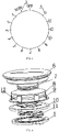
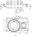
- FIG. 1 shows a multi-gear brightness adjustment circuit board, which includes a plurality of gear conductive contact pieces 2 disposed sequentially along the circumferential direction of the top surface of the circuit board 1 and with gradually increased gear.
- the circuit board 1 is also disposed with an automatic control gear AUTO conductive contact piece 3 and a light spot dot-circle pattern composite conductive contact piece 4 disposed along the circumference of the circuit board 1 in the circumferential direction of the circuit board 1.
- the automatic control gear AUTO conductive contact piece 3 and the light spot dot-circle pattern composite conductive contact piece 4 are sequentially disposed between the OFF gear of the gear conductive contact piece 2 and the maximum gear MAX conductive contact piece of the gear conductive contact piece 2.
- the automatic control gear AUTO conductive contact piece 3 and the light spot dot-circle pattern composite conductive contact piece 4 are respectively disposed closely before and after the OFF gear.
- the automatic control gear AUTO conductive contact piece 3 and the light spot dot-circle pattern composite conductive contact piece 4 are respectively disposed closely before and after the OFF gear, among them, the automatic control gear AUTO conductive contact piece 3 is disposed between the 1 gear conductive contact piece of the gear conductive contact piece 2 and the OFF gear, and the light spot dot-circle pattern composite conductive contact piece 4 is disposed between the OFF gear and the maximum gear MAX conductive contact piece.
- the top surface of the circuit board 1 is disposed with a negative conductive contact point or piece 23 and a positive conductive ring 24.
- the gear conductive contact pieces 2, automatic control gear AUTO conductive contact piece 3 and light spot dot-circle pattern composite conductive contact piece 4 are all disposed on the same circumferential gear ring surface;
- the negative conductive contact point or piece 23, the positive conductive ring 24 and the circumferential gear ring surface are disposed along the radial direction of the circuit board 1, and are respectively disposed on non-intersecting ring surfaces.
- a negative conductive contact 23 and a positive conductive ring 24 are sequentially disposed on the top surface of the circuit board 1 from the inside to the outside.
- the gear conductive contact piece 2, the automatic control gear AUTO conductive contact piece 3 and the light spot dot-circle pattern composite conductive contact piece 4 are all disposed outside the positive conductive ring 24. That is, the positive conductive contact piece and the negative conductive contact piece respectively contact the positive conductive ring 24 and the negative conductive contact point or piece 23 on the circuit board 1 to realize the stable contact and supply of the positive and negative of the power.
- the designer can exchange the positions of the negative conductive contact 23 and the positive conductive ring 24 according to the design requirements, or interchange the positions of the circumferential gear ring surface even interchange any two positions to realize various circuit structures and corresponding specific circuit designs.
- the present embodiment realizes the automatic adjustment of light energy according to the environment through adding the automatic control gear AUTO and the light spot dot-circle mode, and at the same time integrates the target mode on the circuit board, which reduces the number of component parts and facilitates operation.
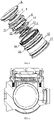
- FIG. 4 shows a multi-gear brightness adjustment assembly (partial structure of the battery holder) containing the aforementioned multi-gear brightness adjustment circuit board, including upper cover 6, insulating pad 7 (rubber pad is generally used), battery 8, positive toothed ring 9, negative circuit board 10, conductive contact piece 11;
- the insulating pad 7 is pressed between the upper cover 6 and the positive of the battery 8 for protection and insulation.
- the battery 8 is clamped in the positive toothed ring 9 to provide positive power supply, and at the same time, it is fixed and limited by the positive toothed ring 9 to ensure that the battery 8 is firmly installed and stable in use.
- the negative circuit board 10 is disposed between the negative of the battery 8 and the conductive contact piece 11.
- the conductive contact piece 11 includes a positive conductive contact piece, a negative conductive contact piece and a gear switching contact piece.
- the positive conductive contact piece and the negative conductive contact piece are respectively in contact with the positive conductive piece and the negative conductive piece on the circuit board 1;
- the gear switching contact piece is used to contact any one of the gear conductive contact piece 2, the automatic control gear AUTO conductive contact piece 3, and the light spot dot-circle pattern composite conductive contact piece to realize the switching of different working states or modes.
- the positive conductive contact piece, the negative conductive contact piece and the gear switching contact piece are in contact with any one of the positive conductive piece, negative conductive piece, the gear conductive contact piece 2, the automatic control gear AUTO conductive contact piece 3, and the light spot dot-circle pattern composite conductive contact piece respectively through the arc-shaped contact points on the bottom surface thereof to ensure the normal shift of gears while realizing the stable power.
- the negative circuit board 10 is disposed with a negative elastic piece 12 that is pressed between the negative of the battery 8 and the negative circuit board 10 and pressed against the negative of the battery 8 to ensure good contact and further stabilize the battery 8.
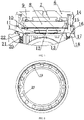
- FIG. 5, FIG. 6 , FIG. 7 show a battery holder structure of a multi-gear brightness adjustment assembly related to the foregoing embodiment, including a first pressing ring 13, an annular rotating cover 14, an annular rotating seat 15, and a second pressing ring 16;
- the first pressing ring 13 is disposed outside the positive toothed ring 9 and presses the top surface edge of the negative circuit board 10 from top to bottom;
- the negative circuit board 10 is suspended on a step on the inner wall of the annular rotating seat 15;
- the second pressing ring 16 is sleeved on the annular step at the bottom end of the outer wall of the annular rotating seat 15;
- the annular rotating cover 14 is sleeved on the top of the annular rotating seat 15 and is spirally connected with the annular rotating seat 15;
- the upper cover 6 is threadedly connected with the upper end of the inner wall of the rotating seat 15;
- the circuit board 1 is fixed on the housing 18 of the peripheral device.
- a sealing ring 17 is
- a plurality of spherical grooves 19 disposed in the circumferential direction are disposed on the bottom edge of the annular rotating seat 15;
- the housing 18 is disposed with at least one blind hole 20 perpendicular to the bottom surface of the annular rotating seat 15, and a coil spring 21 and a steel ball 22 are disposed in the blind hole 20;
- the steel ball 22 and the coil spring 21 are sequentially disposed between the spherical groove 19 and the bottom surface of the blind hole 20, so that a sound can be made when rotating annular rotating cover drives the annular rotating seat to rotate, thereby the user can confirm that the gear adjustment is effective.
- a C-shaped step 25 is disposed on the inner side of the bottom end surface of the annular rotating seat 15;
- An annular step 27 for mounting the circuit board 1 is disposed on the inner side of a mounting hole 26 on the housing 18, and a limit member 28 that can be embedded in the C-shaped step 25 is disposed on the annular step 27, thereby the annular rotating seat 15 rotates positive and negative rotation (that is clockwise and counterclockwise) within a range of less than 360° relative to the plane where the mounting hole 26 is located, both of which are less than 360°.
- a notch 29 recessed radially outward is disposed on the side wall of the mounting hole 26, and the notch 29 is located above the annular step 27, and is used to cooperate with the protrusions on the edge of the circuit board 1 mounted on the annular step 27 to realize the limit of the circuit board 1 to ensure the stable installation of the circuit board.
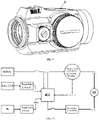
- FIG. 9 is a perspective view of a sight device using the battery holder structure provided by the foregoing embodiment. From this figure, it can be clearly seen that the sight device does not have a separate mode switch, which simplifies the design, reduces the cost, and improves the convenience of use. And the sight device is equipped with a solar cell 5, when using the aforementioned circuit board or battery holder structure, the circuit board 1 includes the MCU processor shown in FIG. 10 , which is used to receive the ambient light signal from the PD sensor that collects ambient light and processed by the signal amplification circuit to calculate the currently required light power. The currently required light power is compared with the energy provided by the power signal from the solar cell, so as to control the battery's release of electric energy and realize the supplement of the energy of the solar cell. On the premise of ensuring that the light power meets the current needs, reduce the demand form battery power, thereby saving battery power and extending battery life.
- the MCU samples the signal of the gear conductive contact piece 2 of the knob switch or automatic control gear AUTO conductive contact piece 3 or the light spot dot-circle pattern composite conductive contact piece 4, in this way, it is known whether the working mode of the circuit is manual gear control mode or automatic gear control, or whether the mode of aiming at the target is photoelectric or dot-circle mode. Therefore, when the gear control mode is the automatic adjustment mode, through sampling the signal of the PD tube and the electric energy signal of the solar cell 5, when the power provided by the solar cell is sufficient, only the power is supplied by the solar cell, and when the power provided by the solar cell cannot meet the working needs, the battery is controlled to supplement the power to ensure that the light power meets the current light demand.
- FIG. 11 is a power circuit diagram of the solar cell 5.
- the regulated power is input to pin 6 of the MCU control chip shown in FIG. 14 through GDC_AN1, and compared with the input signal of the amplified PD sensor collected by pin 5 of the MCU control chip, if the electric energy provided by the current solar cell meets the illuminance demand in the current environment, only the solar cell will supply power, otherwise, the MCU will control the battery to provide power compensation.
- the prerequisite for these functions is that the MCU detects that the gear knob is in the AUTO gear.
- the gear switch When the gear switch is turned to (that is the spot dot-circle composite gear), when the MCU samples the level change of this gear, it will change the LED icons in the other gears.
- the gear switch when the gear turns to the ATUO gear, the state of the inner red dot is a single point; When it turns to gear first, and then reversely turns to AUTO gear, the inner red dot state becomes dot + circle (that is dot-circle) state, that is, the target is composed of a circle and the center of the circle or a cross target.
Claims (9)
- Platine zur Einstellung der Helligkeit mit mehreren Stufen, die mehrere leitfähige Stufen-Kontaktstücke (2) beinhaltet, die an einer Umfangsrichtung einer Oberseite der Platine (1) aufeinanderfolgend und mit zunehmend höherer Stufe positioniert sind,
dadurch gekennzeichnet, dass die Platine (1) auch mit einem leitfähigen Kontaktstück (3) für die Stufe AUTO zur automatischen Steuerung und einem zusammengesetzten leitfähigen Kontaktstück (4) für ein Leuchtpunkt-Punkt/Kreis-Muster positioniert ist, das an der Umfangsrichtung der Platine (1) entlang in der Umfangsrichtung positioniert ist. - Platine zur Einstellung der Helligkeit mit mehreren Stufen nach Anspruch 1, wobei das leitfähige Kontaktstück (3) für die Stufe AUTO zur automatischen Steuerung und das leitfähige Kontaktstück (4) für das zusammengesetzte Leuchtfleck-Punkt/Kreis-Muster aufeinanderfolgend zwischen einem leitfähigen Stufen-Kontaktstück (2) für die Stufe AUS und einem leitfähigen Kontaktstück (2) für die höchste Stufe MAX positioniert sind;
oder das leitfähige Kontaktstück (3) für die Stufe AUTO zur automatischen Steuerung und das leitfähige Kontaktstück (4) für das zusammengesetzte Leuchtfleck-Punkt/Kreis-Muster nahe an einer Vorder- bzw. einer Rückseite der Stufe AUS positioniert sind. - Platine zur Einstellung der Helligkeit mit mehreren Stufen nach Anspruch 2, wobei, wenn das leitfähige Kontaktstück (3) für die Stufe AUTO zur automatischen Steuerung und das leitfähige Kontaktstück (4) für das zusammengesetzte Leuchtfleck-Punkt/Kreis-Muster nahe an der Vorder- bzw. Rückseite der Stufe AUS positioniert ist,
das leitfähige Kontaktstück (3) für die Stufe AUTO zur automatischen Steuerung zwischen einem leitfähigen Kontaktstück für die Stufe 1 des leitfähigen Stufen-Kontaktstücks (2) und der Stufe AUS positioniert ist und das leitfähige Kontaktstück (4) für das zusammengesetzte Leuchtfleck-Punkt/Kreis-Muster zwischen dem leitfähigen Kontaktstück der Stufe AUS und der höchsten Stufe MAX positioniert ist. - Platine zur Einstellung der Helligkeit mit mehreren Stufen nach Anspruch 1 oder 2 oder 3, wobei die Oberseite der Platine (1) mit einem negativen leitfähigen Kontaktpunkt oder -stück (23) und einem positiven leitfähigen Ring (24) versehen ist;das leitfähige Stufen-Kontaktstück (2), das leitfähige Kontaktstück (3) für die Stufe AUTO zur automatischen Steuerung und das leitfähige Kontaktstück (4) für das zusammengesetzte Leuchtfleck-Punkt/Kreis-Muster alle auf derselben Umfangsstufenringfläche positioniert sind;der/das negative leitfähige Kontaktpunkt oder -stück (23), der positive leitfähige Ring (24) und die Umfangsstufenringfläche entlang der Radialrichtung der Platine (1) angeordnet sind und jeweils auf sich nicht schneidenden Ringflächen positioniert sind.
- Batteriehalterkonstruktion, die die Platine zur Einstellung der Helligkeit mit mehreren Stufen nach Anspruch 1 oder 2 oder 3 aufweist, wobei sie eine obere Abdeckung (6), ein Isolierpad (7), eine Batterie (8), einen positiven Zahnring (9), eine negative Platine (10), ein leitfähiges Kontaktstück (11), einen ersten Andrückring (13), eine ringförmige rotierende Abdeckung (14), einen ringförmigen rotierenden Sitz (15) und einen zweiten Andrückring (16) beinhaltet;das Isolierpad (7) zwischen der oberen Abdeckung (6) und einem Pluspol der Batterie (8) eingepresst ist;die Batterie (8) in dem positiven Zahnring (9) eingeklemmt ist;die negative Platine (10) zwischen einem Minuspol der Batterie (8) und dem leitfähigen Kontaktstück (11) positioniert ist;die negative Platine (10) mit einem negativen elastischen Stück (12), das zwischen dem Minuspol der Batterie (8) und der negativen Platine (10) eingepresst ist, positioniert ist;das leitfähige Kontaktstück (11) ein positives leitfähiges Kontaktstück, ein negatives leitfähiges Kontaktstück und ein Stufenumschaltkontaktstück umfasst;das positive leitfähige Kontaktstück und das negative leitfähige Kontaktstück jeweils mit einem positiven leitfähigen Stück und einem negativen leitfähigen Stück auf der Platine (1) in Kontakt sind;das Stufenumschaltkontaktstück verwendet wird, um mit einem von dem leitfähigen Stufenkontaktstück (2), dem leitfähigen Kontaktstück (3) für die Stufe AUTO zur automatischen Steuerung und dem zusammengesetzten leitfähigen Kontaktstück des Lichtpunkt-Punkt/Kreismusters in Kontakt zu kommen, um ein Umschalten verschiedener Betriebszustände oder -modi zu verwirklichen;der erste Andrückring (13) außerhalb des positiven Zahnrings (9) positioniert ist und einen Oberseitenrand der negativen Platine (10) nach unten drückt;die negative Platine (10) an einer Stufe an einer Innenwand des ringförmigen rotierenden Sitzes (15) aufgehängt ist;der zweite Andrückring (16) auf eine ringförmige Stufe an einem unteren Ende einer Außenwand des ringförmigen rotierenden Sitzes (15) aufgeschoben ist;die ringförmige rotierende Abdeckung (14) oben auf den ringförmigen rotierenden Sitz (15) aufgeschoben ist und mit dem ringförmigen rotierenden Sitz (15) spiralförmig verbunden ist;die obere Abdeckung (6) mit einem oberen Ende einer Innenwand des ringförmigen rotierenden Sitzes (15) mittels Gewinde verbunden ist;die Platine (1) an einem Gehäuse (18) einer Peripherievorrichtung befestigt ist.
- Batteriehalterkonstruktion nach Anspruch 5, wobei ein Dichtungsring (17) zwischen dem ringförmigen rotierenden Sitz (15) und einer Montagebohrung am Gehäuse (18) positioniert ist.
- Batteriehalterkonstruktion nach Anspruch 5, wobei an einer unteren Endfläche des ringförmigen rotierenden Sitzes (15) mehrere in einer Umfangsrichtung angeordnete Kugelnuten (19) positioniert sind;das Gehäuse (18) mit wenigstens einem zur unteren Endfläche des ringförmigen rotierenden Sitzes (15) lotrechten Sackloch (20) versehen ist, wobei in dem Sackloch (20) eine Schraubenfeder (21) und eine Stahlkugel (22) positioniert sind;die Stahlkugel (22) und die Schraubenfeder (21) aufeinanderfolgend zwischen der Kugelnut (19) und einer Bodenfläche des Sacklochs (20) positioniert sind;ein C-förmiger Absatz (25) an einer Innenseite einer Unterseitenfläche des ringförmigen rotierenden Sitzes (15) positioniert ist; ein ringförmiger Absatz (27) zum Montieren der Platine (1) an einer Innenseite eines Montagelochs (26) an dem Gehäuse (18) positioniert ist und ein Begrenzungselement (28), das in dem C-förmigen Absatz (25) eingebettet sein kann, an dem ringförmigen Absatz (27) positioniert ist, wodurch der ringförmige rotierende Sitz (15) sich innerhalb eines Bereichs von weniger als 360° im Uhrzeigersinn und gegen den Uhrzeigersinn relativ zu einer Ebene, in der sich die Montagebohrung (26) befindet, dreht.
- Batteriehalterkonstruktion nach Anspruch 7, wobei eine radial nach außen ausgesparte Kerbe (29) an einer Seitenwand des Montagelochs (26) positioniert ist und die Kerbe (29) sich über dem ringförmigen Absatz (27) befindet und zum Zusammenarbeiten mit Vorsprüngen an einem Rand der Platine (1) verwendet wird, die auf dem ringförmigen Absatz (27) montiert sind, um eine Begrenzung der Platine (1) zu verwirklichen.
- Anordnung zur Einstellung der Helligkeit mit mehreren Stufen, die die Platine zur Einstellung der Helligkeit mit mehreren Stufen nach Anspruch 4 beinhaltet, wobei sie eine obere Abdeckung (6), ein Isolierpad (7), eine Batterie (8), einen positiven Zahnring (9), eine negative Platine (10), ein leitfähiges Kontaktstück (11) beinhaltet;das Isolierpad (7) zwischen der oberen Abdeckung (6) und einem Pluspol der Batterie (8) eingepresst ist;die Batterie (8) in dem positiven Zahnring (9) eingespannt ist;die negative Platine (10) zwischen einem Minuspol der Batterie (8) und dem leitfähigen Kontaktstück (11) positioniert ist;die negative Platine (10) mit einem negativen elastischen Stück (12), das zwischen dem Minuspol der Batterie (8) und der negativen Platine (10) eingepresst ist, positioniert ist;das leitfähige Kontaktstück (11) ein positives leitfähiges Kontaktstück, ein negatives leitfähiges Kontaktstück und ein Stufenumschaltkontaktstück umfasst;das positive leitfähige Kontaktstück und das negative leitfähige Kontaktstück mit dem positiven leitfähigen Ring (24) bzw. dem negativen leitfähigen Kontaktpunkt oder -stück (23) auf der Platine (1) in Kontakt sind;das Stufenumschaltkontaktstück verwendet wird, um mit einem von dem leitfähigen Stufenkontaktstück (2), dem leitfähigen Kontaktstück (3) für die Stufe AUTO zur automatischen Steuerung und dem zusammengesetzten leitfähigen Kontaktstück des Lichtpunkt-Punkt/Kreismusters in Kontakt zu kommen, um ein Umschalten verschiedener Betriebszustände oder -modi zu verwirklichen.
Applications Claiming Priority (2)
| Application Number | Priority Date | Filing Date | Title |
|---|---|---|---|
| CN201810416897.4A CN108592700A (zh) | 2018-05-03 | 2018-05-03 | 一种多档位亮度调节电路板、多档位电池座结构 |
| PCT/CN2019/078394 WO2019210746A1 (zh) | 2018-05-03 | 2019-03-16 | 一种多档位亮度调节电路板、多档位电池座结构及多档位亮度调节组件 |
Publications (3)
| Publication Number | Publication Date |
|---|---|
| EP3786571A1 EP3786571A1 (de) | 2021-03-03 |
| EP3786571A4 EP3786571A4 (de) | 2021-06-30 |
| EP3786571B1 true EP3786571B1 (de) | 2022-09-21 |
Family
ID=63619708
Family Applications (1)
| Application Number | Title | Priority Date | Filing Date |
|---|---|---|---|
| EP19797110.4A Active EP3786571B1 (de) | 2018-05-03 | 2019-03-16 | Mehrgang-helligkeitseinstellungsplatine, mehrgang-batteriehalterungsstruktur und mehrgang-helligkeitseinstellungsanordnung |
Country Status (9)
| Country | Link |
|---|---|
| US (1) | US11777166B2 (de) |
| EP (1) | EP3786571B1 (de) |
| JP (1) | JP7053949B2 (de) |
| KR (1) | KR102416119B1 (de) |
| CN (1) | CN108592700A (de) |
| ES (1) | ES2934133T3 (de) |
| HU (1) | HUE060050T2 (de) |
| PL (1) | PL3786571T3 (de) |
| WO (1) | WO2019210746A1 (de) |
Families Citing this family (4)
| Publication number | Priority date | Publication date | Assignee | Title |
|---|---|---|---|---|
| CN108592700A (zh) | 2018-05-03 | 2018-09-28 | 西安华科光电有限公司 | 一种多档位亮度调节电路板、多档位电池座结构 |
| CN109405645B (zh) * | 2018-12-20 | 2024-03-29 | 西安华科光电有限公司 | 一种自适应亮度调节电路及内红点瞄具 |
| IL283500A (en) * | 2021-05-27 | 2022-12-01 | Meprolight 1990 Ltd | Aim for a weapon powered by renewable energy |
| CN117404963B (zh) * | 2023-12-13 | 2024-02-09 | 珠海市霖平光学仪器有限公司 | 一种瞄准镜用双段电源旋钮调节结构 |
Family Cites Families (8)
| Publication number | Priority date | Publication date | Assignee | Title |
|---|---|---|---|---|
| US5493450A (en) * | 1993-11-18 | 1996-02-20 | Ekstrand; Arne | Sighting instrument |
| CN2371764Y (zh) * | 1999-01-22 | 2000-03-29 | 珠海市敏夫光学仪器有限公司 | 一种用于瞄准器的双色多档位亮度调节器 |
| TWI425290B (zh) * | 2008-10-02 | 2014-02-01 | Asia Optical Co Inc | 自動亮度調整系統及瞄準器 |
| US7937879B2 (en) * | 2009-03-11 | 2011-05-10 | Sheltered Wings, Inc. | Rifle scope with a low-light visible element |
| US9982965B2 (en) * | 2014-03-01 | 2018-05-29 | Huanic Corporation | Inner red-dot gun sighting device powered by solar cell and provided with micro-current LED light source |
| WO2016112592A1 (zh) * | 2015-01-18 | 2016-07-21 | 西安华科光电有限公司 | 一种可投射图形标识的led光源及其内红点瞄具 |
| CN104613817B (zh) * | 2015-02-12 | 2016-03-23 | 贵州景浩科技有限公司 | 瞄准器的亮度调节系统和瞄准器 |
| CN108592700A (zh) * | 2018-05-03 | 2018-09-28 | 西安华科光电有限公司 | 一种多档位亮度调节电路板、多档位电池座结构 |
-
2018
- 2018-05-03 CN CN201810416897.4A patent/CN108592700A/zh active Pending
-
2019
- 2019-03-16 ES ES19797110T patent/ES2934133T3/es active Active
- 2019-03-16 US US17/044,255 patent/US11777166B2/en active Active
- 2019-03-16 EP EP19797110.4A patent/EP3786571B1/de active Active
- 2019-03-16 PL PL19797110.4T patent/PL3786571T3/pl unknown
- 2019-03-16 WO PCT/CN2019/078394 patent/WO2019210746A1/zh unknown
- 2019-03-16 HU HUE19797110A patent/HUE060050T2/hu unknown
- 2019-03-16 JP JP2021508044A patent/JP7053949B2/ja active Active
- 2019-03-16 KR KR1020207030801A patent/KR102416119B1/ko active IP Right Grant
Also Published As
| Publication number | Publication date |
|---|---|
| JP7053949B2 (ja) | 2022-04-12 |
| KR102416119B1 (ko) | 2022-07-05 |
| EP3786571A1 (de) | 2021-03-03 |
| US11777166B2 (en) | 2023-10-03 |
| ES2934133T3 (es) | 2023-02-17 |
| CN108592700A (zh) | 2018-09-28 |
| US20210028419A1 (en) | 2021-01-28 |
| HUE060050T2 (hu) | 2023-01-28 |
| PL3786571T3 (pl) | 2023-01-16 |
| WO2019210746A1 (zh) | 2019-11-07 |
| EP3786571A4 (de) | 2021-06-30 |
| KR20200144555A (ko) | 2020-12-29 |
| JP2021519915A (ja) | 2021-08-12 |
Similar Documents
| Publication | Publication Date | Title |
|---|---|---|
| EP3786571B1 (de) | Mehrgang-helligkeitseinstellungsplatine, mehrgang-batteriehalterungsstruktur und mehrgang-helligkeitseinstellungsanordnung | |
| CN208443259U (zh) | 一种多档位亮度调节电路板、多档位亮度调节组件、多档位电池座结构 | |
| CN203480650U (zh) | 落水人员定位报警装置 | |
| US20120019370A1 (en) | Devices and methods for providing wireless command and control to electronic devices | |
| CN213089713U (zh) | 一种用于智慧小区的智能路灯 | |
| CN211178139U (zh) | 开关组亮度调整机构 | |
| CN219123121U (zh) | 一种瞄准镜分划板红绿双色照明的圆弧按键结构 | |
| CN218769197U (zh) | 一种瞄准镜分划板红绿双色照明的平面按键结构 | |
| CN112833710A (zh) | 开关组亮度调整机构 | |
| CN214672829U (zh) | 一种夜视仪供电用电池盒 | |
| CN219697365U (zh) | 一种具有发光模块的无线充电器 | |
| CN218295387U (zh) | 多挡可调探照灯 | |
| CN212341761U (zh) | 一种内置电池的发光旋钮 | |
| CN217877337U (zh) | 一种用于瞄准镜扭圈的快速调节装置 | |
| CN215810461U (zh) | 一种红点瞄具 | |
| CN218514558U (zh) | 智能灯具 | |
| CN218095627U (zh) | 一种便于安装的照明灯具 | |
| CN215647248U (zh) | 一种高清红外半球摄像头用收声结构 | |
| CN214745083U (zh) | 一种警用指挥强光手电 | |
| CN208588272U (zh) | 一种瞄准镜用按压电位器 | |
| CN219389467U (zh) | 一种红外频闪灯 | |
| US20090045770A1 (en) | Headgear assembly capable of collecting solar power | |
| CN220829141U (zh) | 一种充电式的瞄准器 | |
| CN213746475U (zh) | 一种可无线充电的多功能台灯 | |
| CN219534316U (zh) | 一种胃肠镜脚踏开关 |
Legal Events
| Date | Code | Title | Description |
|---|---|---|---|
| STAA | Information on the status of an ep patent application or granted ep patent |
Free format text: STATUS: THE INTERNATIONAL PUBLICATION HAS BEEN MADE |
|
| STAA | Information on the status of an ep patent application or granted ep patent |
Free format text: STATUS: THE INTERNATIONAL PUBLICATION HAS BEEN MADE |
|
| PUAI | Public reference made under article 153(3) epc to a published international application that has entered the european phase |
Free format text: ORIGINAL CODE: 0009012 |
|
| STAA | Information on the status of an ep patent application or granted ep patent |
Free format text: STATUS: REQUEST FOR EXAMINATION WAS MADE |
|
| 17P | Request for examination filed |
Effective date: 20201124 |
|
| AK | Designated contracting states |
Kind code of ref document: A1 Designated state(s): AL AT BE BG CH CY CZ DE DK EE ES FI FR GB GR HR HU IE IS IT LI LT LU LV MC MK MT NL NO PL PT RO RS SE SI SK SM TR |
|
| AX | Request for extension of the european patent |
Extension state: BA ME |
|
| A4 | Supplementary search report drawn up and despatched |
Effective date: 20210528 |
|
| RIC1 | Information provided on ipc code assigned before grant |
Ipc: H05B 45/30 20200101AFI20210521BHEP Ipc: H05B 45/10 20200101ALI20210521BHEP Ipc: H05B 47/11 20200101ALI20210521BHEP Ipc: F41G 1/30 20060101ALI20210521BHEP |
|
| DAV | Request for validation of the european patent (deleted) | ||
| DAX | Request for extension of the european patent (deleted) | ||
| REG | Reference to a national code |
Ref country code: DE Ref legal event code: R079 Ref document number: 602019019876 Country of ref document: DE Free format text: PREVIOUS MAIN CLASS: F41G0001000000 Ipc: F41G0001300000 |
|
| GRAP | Despatch of communication of intention to grant a patent |
Free format text: ORIGINAL CODE: EPIDOSNIGR1 |
|
| STAA | Information on the status of an ep patent application or granted ep patent |
Free format text: STATUS: GRANT OF PATENT IS INTENDED |
|
| RIC1 | Information provided on ipc code assigned before grant |
Ipc: H01H 19/54 20060101ALN20220331BHEP Ipc: H01H 19/10 20060101ALN20220331BHEP Ipc: H05K 1/11 20060101ALI20220331BHEP Ipc: H01M 50/284 20210101ALI20220331BHEP Ipc: H01M 50/247 20210101ALI20220331BHEP Ipc: H01M 50/202 20210101ALI20220331BHEP Ipc: H05B 47/11 20200101ALI20220331BHEP Ipc: H05B 45/10 20200101ALI20220331BHEP Ipc: H05B 45/30 20200101ALI20220331BHEP Ipc: F41G 1/30 20060101AFI20220331BHEP |
|
| INTG | Intention to grant announced |
Effective date: 20220414 |
|
| GRAS | Grant fee paid |
Free format text: ORIGINAL CODE: EPIDOSNIGR3 |
|
| GRAA | (expected) grant |
Free format text: ORIGINAL CODE: 0009210 |
|
| STAA | Information on the status of an ep patent application or granted ep patent |
Free format text: STATUS: THE PATENT HAS BEEN GRANTED |
|
| AK | Designated contracting states |
Kind code of ref document: B1 Designated state(s): AL AT BE BG CH CY CZ DE DK EE ES FI FR GB GR HR HU IE IS IT LI LT LU LV MC MK MT NL NO PL PT RO RS SE SI SK SM TR |
|
| REG | Reference to a national code |
Ref country code: GB Ref legal event code: FG4D |
|
| REG | Reference to a national code |
Ref country code: CH Ref legal event code: EP |
|
| REG | Reference to a national code |
Ref country code: DE Ref legal event code: R096 Ref document number: 602019019876 Country of ref document: DE |
|
| REG | Reference to a national code |
Ref country code: IE Ref legal event code: FG4D |
|
| REG | Reference to a national code |
Ref country code: AT Ref legal event code: REF Ref document number: 1520147 Country of ref document: AT Kind code of ref document: T Effective date: 20221015 |
|
| REG | Reference to a national code |
Ref country code: EE Ref legal event code: FG4A Ref document number: E022807 Country of ref document: EE Effective date: 20221004 |
|
| REG | Reference to a national code |
Ref country code: SE Ref legal event code: TRGR |
|
| REG | Reference to a national code |
Ref country code: LT Ref legal event code: MG9D |
|
| REG | Reference to a national code |
Ref country code: NL Ref legal event code: MP Effective date: 20220921 |
|
| REG | Reference to a national code |
Ref country code: HU Ref legal event code: AG4A Ref document number: E060050 Country of ref document: HU |
|
| PG25 | Lapsed in a contracting state [announced via postgrant information from national office to epo] |
Ref country code: RS Free format text: LAPSE BECAUSE OF FAILURE TO SUBMIT A TRANSLATION OF THE DESCRIPTION OR TO PAY THE FEE WITHIN THE PRESCRIBED TIME-LIMIT Effective date: 20220921 Ref country code: NO Free format text: LAPSE BECAUSE OF FAILURE TO SUBMIT A TRANSLATION OF THE DESCRIPTION OR TO PAY THE FEE WITHIN THE PRESCRIBED TIME-LIMIT Effective date: 20221221 Ref country code: LV Free format text: LAPSE BECAUSE OF FAILURE TO SUBMIT A TRANSLATION OF THE DESCRIPTION OR TO PAY THE FEE WITHIN THE PRESCRIBED TIME-LIMIT Effective date: 20220921 Ref country code: LT Free format text: LAPSE BECAUSE OF FAILURE TO SUBMIT A TRANSLATION OF THE DESCRIPTION OR TO PAY THE FEE WITHIN THE PRESCRIBED TIME-LIMIT Effective date: 20220921 Ref country code: FI Free format text: LAPSE BECAUSE OF FAILURE TO SUBMIT A TRANSLATION OF THE DESCRIPTION OR TO PAY THE FEE WITHIN THE PRESCRIBED TIME-LIMIT Effective date: 20220921 |
|
| REG | Reference to a national code |
Ref country code: AT Ref legal event code: MK05 Ref document number: 1520147 Country of ref document: AT Kind code of ref document: T Effective date: 20220921 |
|
| REG | Reference to a national code |
Ref country code: ES Ref legal event code: FG2A Ref document number: 2934133 Country of ref document: ES Kind code of ref document: T3 Effective date: 20230217 |
|
| PG25 | Lapsed in a contracting state [announced via postgrant information from national office to epo] |
Ref country code: HR Free format text: LAPSE BECAUSE OF FAILURE TO SUBMIT A TRANSLATION OF THE DESCRIPTION OR TO PAY THE FEE WITHIN THE PRESCRIBED TIME-LIMIT Effective date: 20220921 Ref country code: GR Free format text: LAPSE BECAUSE OF FAILURE TO SUBMIT A TRANSLATION OF THE DESCRIPTION OR TO PAY THE FEE WITHIN THE PRESCRIBED TIME-LIMIT Effective date: 20221222 |
|
| PG25 | Lapsed in a contracting state [announced via postgrant information from national office to epo] |
Ref country code: SM Free format text: LAPSE BECAUSE OF FAILURE TO SUBMIT A TRANSLATION OF THE DESCRIPTION OR TO PAY THE FEE WITHIN THE PRESCRIBED TIME-LIMIT Effective date: 20220921 Ref country code: RO Free format text: LAPSE BECAUSE OF FAILURE TO SUBMIT A TRANSLATION OF THE DESCRIPTION OR TO PAY THE FEE WITHIN THE PRESCRIBED TIME-LIMIT Effective date: 20220921 Ref country code: PT Free format text: LAPSE BECAUSE OF FAILURE TO SUBMIT A TRANSLATION OF THE DESCRIPTION OR TO PAY THE FEE WITHIN THE PRESCRIBED TIME-LIMIT Effective date: 20230123 Ref country code: CZ Free format text: LAPSE BECAUSE OF FAILURE TO SUBMIT A TRANSLATION OF THE DESCRIPTION OR TO PAY THE FEE WITHIN THE PRESCRIBED TIME-LIMIT Effective date: 20220921 Ref country code: AT Free format text: LAPSE BECAUSE OF FAILURE TO SUBMIT A TRANSLATION OF THE DESCRIPTION OR TO PAY THE FEE WITHIN THE PRESCRIBED TIME-LIMIT Effective date: 20220921 |
|
| PGFP | Annual fee paid to national office [announced via postgrant information from national office to epo] |
Ref country code: FR Payment date: 20230322 Year of fee payment: 5 |
|
| PG25 | Lapsed in a contracting state [announced via postgrant information from national office to epo] |
Ref country code: SK Free format text: LAPSE BECAUSE OF FAILURE TO SUBMIT A TRANSLATION OF THE DESCRIPTION OR TO PAY THE FEE WITHIN THE PRESCRIBED TIME-LIMIT Effective date: 20220921 Ref country code: IS Free format text: LAPSE BECAUSE OF FAILURE TO SUBMIT A TRANSLATION OF THE DESCRIPTION OR TO PAY THE FEE WITHIN THE PRESCRIBED TIME-LIMIT Effective date: 20230121 |
|
| PGFP | Annual fee paid to national office [announced via postgrant information from national office to epo] |
Ref country code: TR Payment date: 20230314 Year of fee payment: 5 Ref country code: SE Payment date: 20230322 Year of fee payment: 5 Ref country code: PL Payment date: 20230308 Year of fee payment: 5 Ref country code: HU Payment date: 20230314 Year of fee payment: 5 Ref country code: GB Payment date: 20230322 Year of fee payment: 5 Ref country code: EE Payment date: 20230322 Year of fee payment: 5 Ref country code: DE Payment date: 20230330 Year of fee payment: 5 |
|
| REG | Reference to a national code |
Ref country code: DE Ref legal event code: R097 Ref document number: 602019019876 Country of ref document: DE |
|
| PG25 | Lapsed in a contracting state [announced via postgrant information from national office to epo] |
Ref country code: NL Free format text: LAPSE BECAUSE OF FAILURE TO SUBMIT A TRANSLATION OF THE DESCRIPTION OR TO PAY THE FEE WITHIN THE PRESCRIBED TIME-LIMIT Effective date: 20220921 Ref country code: AL Free format text: LAPSE BECAUSE OF FAILURE TO SUBMIT A TRANSLATION OF THE DESCRIPTION OR TO PAY THE FEE WITHIN THE PRESCRIBED TIME-LIMIT Effective date: 20220921 |
|
| PLBE | No opposition filed within time limit |
Free format text: ORIGINAL CODE: 0009261 |
|
| STAA | Information on the status of an ep patent application or granted ep patent |
Free format text: STATUS: NO OPPOSITION FILED WITHIN TIME LIMIT |
|
| PG25 | Lapsed in a contracting state [announced via postgrant information from national office to epo] |
Ref country code: DK Free format text: LAPSE BECAUSE OF FAILURE TO SUBMIT A TRANSLATION OF THE DESCRIPTION OR TO PAY THE FEE WITHIN THE PRESCRIBED TIME-LIMIT Effective date: 20220921 |
|
| PGFP | Annual fee paid to national office [announced via postgrant information from national office to epo] |
Ref country code: IT Payment date: 20230331 Year of fee payment: 5 Ref country code: ES Payment date: 20230403 Year of fee payment: 5 |
|
| 26N | No opposition filed |
Effective date: 20230622 |
|
| PG25 | Lapsed in a contracting state [announced via postgrant information from national office to epo] |
Ref country code: SI Free format text: LAPSE BECAUSE OF FAILURE TO SUBMIT A TRANSLATION OF THE DESCRIPTION OR TO PAY THE FEE WITHIN THE PRESCRIBED TIME-LIMIT Effective date: 20220921 |
|
| PG25 | Lapsed in a contracting state [announced via postgrant information from national office to epo] |
Ref country code: MC Free format text: LAPSE BECAUSE OF FAILURE TO SUBMIT A TRANSLATION OF THE DESCRIPTION OR TO PAY THE FEE WITHIN THE PRESCRIBED TIME-LIMIT Effective date: 20220921 |
|
| REG | Reference to a national code |
Ref country code: CH Ref legal event code: PL |
|
| REG | Reference to a national code |
Ref country code: BE Ref legal event code: MM Effective date: 20230331 |
|
| PG25 | Lapsed in a contracting state [announced via postgrant information from national office to epo] |
Ref country code: LU Free format text: LAPSE BECAUSE OF NON-PAYMENT OF DUE FEES Effective date: 20230316 |
|
| REG | Reference to a national code |
Ref country code: IE Ref legal event code: MM4A |
|
| PG25 | Lapsed in a contracting state [announced via postgrant information from national office to epo] |
Ref country code: LI Free format text: LAPSE BECAUSE OF NON-PAYMENT OF DUE FEES Effective date: 20230331 Ref country code: IE Free format text: LAPSE BECAUSE OF NON-PAYMENT OF DUE FEES Effective date: 20230316 Ref country code: CH Free format text: LAPSE BECAUSE OF NON-PAYMENT OF DUE FEES Effective date: 20230331 |
|
| PG25 | Lapsed in a contracting state [announced via postgrant information from national office to epo] |
Ref country code: BE Free format text: LAPSE BECAUSE OF NON-PAYMENT OF DUE FEES Effective date: 20230331 |