EP3786408A1 - Objektbewegungsvorrichtung - Google Patents
Objektbewegungsvorrichtung Download PDFInfo
- Publication number
- EP3786408A1 EP3786408A1 EP19792309.7A EP19792309A EP3786408A1 EP 3786408 A1 EP3786408 A1 EP 3786408A1 EP 19792309 A EP19792309 A EP 19792309A EP 3786408 A1 EP3786408 A1 EP 3786408A1
- Authority
- EP
- European Patent Office
- Prior art keywords
- changing
- guide member
- cable
- changing member
- carrier plate
- Prior art date
- Legal status (The legal status is an assumption and is not a legal conclusion. Google has not performed a legal analysis and makes no representation as to the accuracy of the status listed.)
- Withdrawn
Links
Images




Classifications
-
- E—FIXED CONSTRUCTIONS
- E05—LOCKS; KEYS; WINDOW OR DOOR FITTINGS; SAFES
- E05F—DEVICES FOR MOVING WINGS INTO OPEN OR CLOSED POSITION; CHECKS FOR WINGS; WING FITTINGS NOT OTHERWISE PROVIDED FOR, CONCERNED WITH THE FUNCTIONING OF THE WING
- E05F15/00—Power-operated mechanisms for wings
- E05F15/60—Power-operated mechanisms for wings using electrical actuators
- E05F15/603—Power-operated mechanisms for wings using electrical actuators using rotary electromotors
- E05F15/665—Power-operated mechanisms for wings using electrical actuators using rotary electromotors for vertically-sliding wings
- E05F15/689—Power-operated mechanisms for wings using electrical actuators using rotary electromotors for vertically-sliding wings specially adapted for vehicle windows
-
- E—FIXED CONSTRUCTIONS
- E05—LOCKS; KEYS; WINDOW OR DOOR FITTINGS; SAFES
- E05F—DEVICES FOR MOVING WINGS INTO OPEN OR CLOSED POSITION; CHECKS FOR WINGS; WING FITTINGS NOT OTHERWISE PROVIDED FOR, CONCERNED WITH THE FUNCTIONING OF THE WING
- E05F11/00—Man-operated mechanisms for operating wings, including those which also operate the fastening
- E05F11/38—Man-operated mechanisms for operating wings, including those which also operate the fastening for sliding windows, e.g. vehicle windows, to be opened or closed by vertical movement
- E05F11/48—Man-operated mechanisms for operating wings, including those which also operate the fastening for sliding windows, e.g. vehicle windows, to be opened or closed by vertical movement operated by cords or chains or other flexible elongated pulling elements, e.g. tapes
- E05F11/481—Man-operated mechanisms for operating wings, including those which also operate the fastening for sliding windows, e.g. vehicle windows, to be opened or closed by vertical movement operated by cords or chains or other flexible elongated pulling elements, e.g. tapes for vehicle windows
- E05F11/483—Man-operated mechanisms for operating wings, including those which also operate the fastening for sliding windows, e.g. vehicle windows, to be opened or closed by vertical movement operated by cords or chains or other flexible elongated pulling elements, e.g. tapes for vehicle windows by cables
-
- E—FIXED CONSTRUCTIONS
- E05—LOCKS; KEYS; WINDOW OR DOOR FITTINGS; SAFES
- E05Y—INDEXING SCHEME ASSOCIATED WITH SUBCLASSES E05D AND E05F, RELATING TO CONSTRUCTION ELEMENTS, ELECTRIC CONTROL, POWER SUPPLY, POWER SIGNAL OR TRANSMISSION, USER INTERFACES, MOUNTING OR COUPLING, DETAILS, ACCESSORIES, AUXILIARY OPERATIONS NOT OTHERWISE PROVIDED FOR, APPLICATION THEREOF
- E05Y2201/00—Constructional elements; Accessories therefor
- E05Y2201/60—Suspension or transmission members; Accessories therefor
- E05Y2201/622—Suspension or transmission members elements
- E05Y2201/644—Flexible elongated pulling elements
- E05Y2201/654—Cables
-
- E—FIXED CONSTRUCTIONS
- E05—LOCKS; KEYS; WINDOW OR DOOR FITTINGS; SAFES
- E05Y—INDEXING SCHEME ASSOCIATED WITH SUBCLASSES E05D AND E05F, RELATING TO CONSTRUCTION ELEMENTS, ELECTRIC CONTROL, POWER SUPPLY, POWER SIGNAL OR TRANSMISSION, USER INTERFACES, MOUNTING OR COUPLING, DETAILS, ACCESSORIES, AUXILIARY OPERATIONS NOT OTHERWISE PROVIDED FOR, APPLICATION THEREOF
- E05Y2201/00—Constructional elements; Accessories therefor
- E05Y2201/60—Suspension or transmission members; Accessories therefor
- E05Y2201/622—Suspension or transmission members elements
- E05Y2201/658—Members cooperating with flexible elongated pulling elements
- E05Y2201/668—Pulleys; Wheels
-
- E—FIXED CONSTRUCTIONS
- E05—LOCKS; KEYS; WINDOW OR DOOR FITTINGS; SAFES
- E05Y—INDEXING SCHEME ASSOCIATED WITH SUBCLASSES E05D AND E05F, RELATING TO CONSTRUCTION ELEMENTS, ELECTRIC CONTROL, POWER SUPPLY, POWER SIGNAL OR TRANSMISSION, USER INTERFACES, MOUNTING OR COUPLING, DETAILS, ACCESSORIES, AUXILIARY OPERATIONS NOT OTHERWISE PROVIDED FOR, APPLICATION THEREOF
- E05Y2600/00—Mounting or coupling arrangements for elements provided for in this subclass
- E05Y2600/50—Mounting methods; Positioning
- E05Y2600/52—Toolless
-
- E—FIXED CONSTRUCTIONS
- E05—LOCKS; KEYS; WINDOW OR DOOR FITTINGS; SAFES
- E05Y—INDEXING SCHEME ASSOCIATED WITH SUBCLASSES E05D AND E05F, RELATING TO CONSTRUCTION ELEMENTS, ELECTRIC CONTROL, POWER SUPPLY, POWER SIGNAL OR TRANSMISSION, USER INTERFACES, MOUNTING OR COUPLING, DETAILS, ACCESSORIES, AUXILIARY OPERATIONS NOT OTHERWISE PROVIDED FOR, APPLICATION THEREOF
- E05Y2600/00—Mounting or coupling arrangements for elements provided for in this subclass
- E05Y2600/60—Mounting or coupling members; Accessories therefor
- E05Y2600/626—Plates or brackets
-
- E—FIXED CONSTRUCTIONS
- E05—LOCKS; KEYS; WINDOW OR DOOR FITTINGS; SAFES
- E05Y—INDEXING SCHEME ASSOCIATED WITH SUBCLASSES E05D AND E05F, RELATING TO CONSTRUCTION ELEMENTS, ELECTRIC CONTROL, POWER SUPPLY, POWER SIGNAL OR TRANSMISSION, USER INTERFACES, MOUNTING OR COUPLING, DETAILS, ACCESSORIES, AUXILIARY OPERATIONS NOT OTHERWISE PROVIDED FOR, APPLICATION THEREOF
- E05Y2800/00—Details, accessories and auxiliary operations not otherwise provided for
- E05Y2800/67—Materials; Strength alteration thereof
- E05Y2800/674—Metal
-
- E—FIXED CONSTRUCTIONS
- E05—LOCKS; KEYS; WINDOW OR DOOR FITTINGS; SAFES
- E05Y—INDEXING SCHEME ASSOCIATED WITH SUBCLASSES E05D AND E05F, RELATING TO CONSTRUCTION ELEMENTS, ELECTRIC CONTROL, POWER SUPPLY, POWER SIGNAL OR TRANSMISSION, USER INTERFACES, MOUNTING OR COUPLING, DETAILS, ACCESSORIES, AUXILIARY OPERATIONS NOT OTHERWISE PROVIDED FOR, APPLICATION THEREOF
- E05Y2900/00—Application of doors, windows, wings or fittings thereof
- E05Y2900/50—Application of doors, windows, wings or fittings thereof for vehicles
- E05Y2900/53—Type of wing
- E05Y2900/55—Windows
Definitions
- the present invention relates to an object moving device.
- a cable attached to the object is used in order to transmit a driving force.
- This cable is usually connected to a carrier plate attached to the object to be moved (hereinafter, referred to as “movement object”) and a drive section, and is routed such that a direction in which the cable extends (hereinafter, referred to as “cable extending direction”) is changed by a direction-changing portion such as a pulley.
- a portion supporting the direction-changing portion requires strength to prevent the direction-changing portion from coming off.
- PTL Patent Literature 1
- an attempt to improve the strength is made through provision of a rib in a portion to which a pulley serving as the direction-changing portion is fixed.
- the window regulator of PTL 1 requires a complicated rib structure to be provided in addition to a range corresponding to the direction-changing portion to ensure strength.
- An object of the present invention is to provide an object moving device including a direction-changing portion for which strength is ensured with a simple structure.
- the object moving device of the present invention includes:
- An object moving device is a device for moving a carrier plate by transmitting a driving force of a drive section to the carrier plate via a cable.
- the movement object for the object moving device may be the carrier plate itself or an object that is different from the object moving device and is connected to the object moving device.
- Object moving device 1 of the present embodiment may be used in any device as long as the device moves carrier plate 30, and can be used in a window glass raising and lowering device or other devices.
- the other devices to which object moving device 1 may be applied include, for example, a device that raises and lowers a window glass, a metal plate or a plate made of a resin.
- a plate made of a resin As other opaque plates such as a plate made of a resin, a plate capable of displaying a captured image or the like, such as of a surrounding scenery similar to a surrounding scenery visible through a glass, may be used.
- the other devices to which object moving device 1 can be applied also include, for example, a walking assisting device that assists a pedestrian in walking by raising and lowering a handle that the pedestrian holds.
- object moving device 1 illustrated in FIG. 1 is fixed between an inner panel and an outer panel of a door of a vehicle, and is applied to a window regulator or the like that raises and lowers a window of the door (for example, a window glass).
- the movement object is window glass W supported by carrier plate 30.
- a moving direction of carrier plate 30 is an up-down direction defined by using as a reference a raising and lowering direction of window glass W, which is the movement object.
- object moving device 1 includes, in addition to carrier plate 30, drive section 20, guide member 40, cable 60, first direction-changing member 100, and second direction-changing member 70. Note that, this configuration is applicable to second direction-changing member 70 and an attachment part of the guide member to which second direction-changing member 70 is attached.
- Drive section 20 moves carrier plate 30 upward and downward via cable 60.
- Drive section 20 moves carrier plate 30 by winding and unwinding cable 60.
- Drive section 20 is connected to one end of cable 60, that is, one end of raising cable 62 and one end of lowering cable 64 in the present embodiment, respectively.
- drive section 20 includes motor 22 that is electrically driven, drum 24, and a power transmission section (not illustrated) that transmits rotational motion of motor 22 to drum 24, such as a worm gear, for example.
- Drive section 20 rotationally drives motor 22 in a forward direction and in a backward direction, and drum 24 rotates in the forward direction and in the backward direction by the rotational driving.
- drive section 20 is held, between one end and another end of guide member 40, by drive section-fixing portion 46 provided in guide member 40.
- drum 24 rotates in the forward direction and in the backward direction.
- the one ends (in this case, the respective one ends) of raising cable 62 and lowering cable 64 are connected to drum 24 in which raising cable 62 and lowering cable 64 are wound in opposite directions to each other.
- Drum 24 winds raising cable 62 by the rotation in the forward direction or in the backward direction to pull raising cable 62, or winds lowering cable 64 thereby to pull lowering cable 64.
- Drum 24 unwinds lowering cable 64 when drum 24 winds raising cable 62, and unwinds raising cable 62 when drum 24 winds lowering cable 64.
- drive section 20 is provided between one end portion 42 and another end portion 44 of guide member 40, but may be provided in another end portion 44 of guide member 40. Further, in a configuration in which first direction-changing member 100 is provided not in one end portion 42, but in another end portion 44 in guide member 40, drive section 20 can also be provided in one end portion 42 of guide member 40. Furthermore, drive section 20 is provided in guide member 40 in the present embodiment, but may be disposed away from guide member 40.
- carrier plate 30 itself may be the movement object.
- Carrier plate 30 is moved by drive section 20 via cable 60. In a case where the movement object is connected to carrier plate 30, carrier plate 30 moves the movement object.
- carrier plate 30 is fitted into guide member 40, and is guided by guide member 40 to move upward and downward.
- Carrier plate 30 is fitted into rail portion 41 extending between a side of the one end and a side of the other end of guide member 40, and is freely movable along rail portion 41.
- Carrier plate 30 is movable upward and downward by being guided by rail portion 41.
- carrier plate 30 holds a lower end portion of window glass W, and is guided along guide member 40 (specifically, rail portion 41 of guide member 40) in the raising and lowering direction of window glass W.
- Carrier plate 30 moves between a side of one end portion 42 (the side of the upper end in FIG. 1 ) and a side of another end portion 44 (the side of the lower end in FIG. 1 ) of guide member 40, and moves window glass W, which is the movement object.
- Cable 60 is a member that moves carrier plate 30 in the up-down direction indicated by an arrow in FIG. 1 .
- Cable 60 is moved by a driving force of drive section 20.
- Cable 60 is a long member that connects drive section 20 and carrier plate 30, and transmits the driving force generated by drive section 20 to carrier plate 30.
- Cable 60 moves carrier plate 30 in the up-down direction by converting the driving force of drive section 20 into a tensile force to pull carrier plate 30.
- cable 60 for example, a wire formed by twisting a plurality of at least one of metal element wires and resin fiber element wires can be used.
- Cable 60 has flexibility enabling the direction of cable 60 to be changed by first direction-changing member 100 and second direction-changing member 70, for example.
- Cable 60 is linearly disposed, in a state in which tension is applied thereto, in a region between drive section 20 and first direction-changing member 100, in a region between first direction-changing member 100 and carrier plate 30, in a region between carrier plate 30 and second direction-changing member 70, and in a region between second direction-changing member 70 and drive section 20, for example.
- carrier plate 30 moves in the up-down direction in conjunction with the driving of drive section 20.
- cable 60 includes raising cable 62 and lowering cable 64.
- Raising cable 62 pulls carrier plate 30 upward.
- Raising cable 62 is connected to carrier plate 30 at another end of raising cable 62, is wound around direction-changing portion (a pulley in the present embodiment) 110 of first direction-changing member 100 above, and is connected to drum 24 of drive section 20 at one end of raising cable 62.
- Lowering cable 64 pulls carrier plate 30 downward.
- Lowering cable 64 is connected to carrier plate 30 at another end of lowering cable 64, is wound around second direction-changing member 70 (for example, a pulley) below, and is connected to drum 24 of drive section 20 at one end of lowering cable 64.
- second direction-changing member 70 for example, a pulley
- Guide member 40 guides the movement of carrier plate 30, and movably supports carrier plate 30.
- a rotation regulation portion such as a rib, that restrains carrier plate 30 from rotating in an axial direction of guide member 40, is provided in a longitudinal direction, that is, in an extending direction of guide member 40.
- Rail portion 41 is formed by the rotation regulation portion.
- Guide member 40 supports carrier plate 30 such that carrier plate 30 is capable of being raised and lowered along the extending direction of guide member 40 (a direction in which guide member 40 extends).
- guide member 40 is formed of a resin material, and the weight of guide member 40 is reduced compared to a conventional guide rail made of a metal.
- Guide member 40 is formed in a curved shape as a whole such that a central portion thereof between one end portion 42 and another end portion 44 protrudes on a side of one surface, in this case, a surface on which carrier plate 30 is disposed.
- guide member 40 includes drive section-fixing portion 46 that fixes drive section 20 at a position deviated in the width direction of rail portion 41 from the position of rail portion 41 extending in the longitudinal direction.
- Guide member 40 is disposed such that rail portion 41 extends in the up-down direction.
- the width direction described here is a direction perpendicular to the extending direction of guide member 40, more specifically, the left-right direction of object moving device 1 corresponding to the width direction of the movement object.
- attachment portion 420 to which first direction-changing member 100 is attached is provided on the side of one end portion 42 (here, the side of the upper end) of guide member 40, and second direction-changing member 70 is attached on the side of another end portion 44 (here, the side of the lower end) of guide member 40.
- Drive section-fixing portion 46 is disposed between one end portion 42 and another end portion 44.
- Drive section-fixing portion 46 is disposed between one end portion 42 and another end portion 44 in the extending direction, and away from rail portion 41 in the width direction of rail portion 41.
- drum 24 is provided to be rotatable by the driving of motor 22.
- all of the extending direction of guide member 40 and the moving directions of raising cable 62 and lowering cable 64 are up-down directions in accordance with the movement of carrier plate 30 in the up-down direction, but are not limited thereto.
- the moving direction of carrier plate 30 is a direction different from the up-down direction
- the extending direction of guide member 40 and the moving directions of raising cable 62 and lowering cable 64 may be any directions such as left-right directions, for example. These moving directions can be appropriately set depending on the moving direction of the movement object.
- Second direction-changing member 70 is attached on the side of another end portion 44. Specifically, a pulley shaft freely rotatably supporting the pulley that is second direction-changing member 70 is attached to another end portion 44. By fixing of the pulley shaft to another end portion 44, the pulley of second direction-changing member 70 is freely rotatably attached to guide member 40, and the moving direction of lowering cable 64 wound around the pulley is changed.
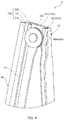
- FIG. 4 is a partial perspective view of first direction-changing member 100 in object moving device 1 illustrated in FIG. 1 .
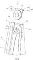
- FIG. 5 is a partial perspective view of a state in which first direction-changing member 100 is removed from guide member 40 in object moving device 1 illustrated in FIG. 1 .
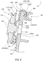
- FIG. 6 is a cross-sectional view in an arrow direction taken along line A-A of FIG. 1 . Note that, illustration of raising cable 62 is omitted in FIG. 4 to FIG. 6 for convenience. Similarly, illustration of raising cable 62 is omitted in FIG. 7 to FIG. 9 as well.
- First direction-changing member 100 is attached to attachment portion 420 by movement of rigid portion 130 of first direction-changing member 100, which is a first direction-changing member, from a position apart in the extending direction of guide member 40 to be fitted into attachment portion 420.
- Attachment portion 420 is provided to allow first direction-changing member 100 to be fitted into attachment portion 420 from above.
- Attachment portion 420 includes first fitting portion 422 and second fitting portion 424, and is fitted into first direction-changing member 100 at first and second fitting portions 422 and 424 described above.
- First fitting portion 422 regulates relative movements of guide member 40 and first direction-changing member 100 in the extending direction of guide member 40.
- first fitting portion 422 is fitted into a fitted portion (a first fitted portion) that is a part of first direction-changing member 100 to regulate the movement of first direction-changing member 100 in the one direction.
- first fitting portion 422 is a groove portion opening upward and provided in an upper end portion that is one end portion 42 of guide member 40. Movement regulation portion 134 of first direction-changing member 100 is inserted and fitted into the groove portion to regulate the movement of first direction-changing member 100 in the one direction with respect to guide member 40. Note that, end surface portion 1342 of first direction-changing member 100 abuts on end surface 42a in one end portion 42 of guide member 40 between first fitting portion 422 and second fitting portion 424 to regulate movement of end surface portion 1342 in the one direction.
- second fitting portion 424 is provided on a surface of a side, to which the movement object is connected, of carrier plate 30, and in a U-shaped peripheral wall portion opening upward.
- second fitting portion 424 corresponds to the both side wall portions of the peripheral wall portion.
- the peripheral wall portion includes a U-shaped groove formed therein.
- Second fitting portion 424 is fitted into rigid portion 130 by insertion of both side end portions in the width direction of rigid portion 130 into the groove provided in the both side wall portions of the peripheral wall portion.
- Second fitting portion 424 may include a bottom-shaped portion of the U-shape of the peripheral wall portion.
- abutting surface portion 426 is provided in the inside the peripheral wall portion of second fitting portion 424.
- Abutting surface portion 426 is provided along at least the inside of the peripheral wall portion in one end portion 42, and functions as a plane supporting rigid portion 130 in a state in which first direction-changing member 100 is attached to attachment portion 420.
- guide member 40 On the side of one end portion 42, guide member 40 includes a space recessed in the width direction of guide member 40 with respect to second fitting portion 424, and is provided with abutting surface portion 426 as a bottom in the width direction of guide member 40 of the space.
- rigid portion-main body 132 of rigid portion 130 abuts on abutting surface portion 426 to support rigid portion 130.
- Abutting surface portion 426 is provided with through-hole 426a.
- through-hole 426a makes it possible to attach first direction-changing member 100 to attachment portion 420 without allowing abutting surface portion 426 to interfere with support portion 120.
- the plane may be provided anywhere as long as the plane is provided along second fitting portion 424 and supports rigid portion 130 in a state in which first direction-changing member 100 is attached to attachment portion 420.
- the plane may be a wall surface of at least one of both side walls of the groove constituting first fitting portion 422.
- FIG. 7 is a partial cross-sectional view of a configuration of a main portion of object moving device 1A that is Variation 1 of object moving device 1.
- object moving device 1A includes both side wall portions 4222 in which a groove is deepened in first fitting portion 422A as a groove portion and which extend in an extending direction of guide member 40A.
- First fitting portion 422A described above makes it possible to accommodate auxiliary surface portion 1344A of movement regulation portion 134 in which an area facing rigid portion-main body 132A is widened in first direction-changing member 100A.
- attachment portion 420A is capable of supporting rigid portion 130A of direction-changing member 100A with a wide area of both side wall portions 4222.
- Direction-changing members (70, 100) illustrated in FIG. 1 to FIG. 6 change the moving direction of cable 60 on guide member 40.
- direction-changing members (70, 100) a resin-made guide having elasticity to guide cable 60 along a changing direction, a pulley or the like is used, for example.
- Direction-changing members (70, 100) are disposed apart in the moving direction of carrier plate 30.
- direction-changing members (70, 100) are provided on upper and lower end portions 42 and 44 of guide member 40, respectively.
- Second direction changing member 70 changes motion of pulling up a side of the one end of lowering cable 64 connected to drum 24 upward to motion of pulling down the side of the other end connected to carrier plate 30 downward.
- second direction changing member 70 includes a pulley including a groove around which lowering cable 64 is wound, and a pulley shaft that freely rotatably supports the pulley on a side of a leading end. By fixing of a side of a base end of the pulley shaft at a predetermined position of another end portion 44 of guide member 40, second direction-changing member 70 is fixed to guide member 40.
- raising cable 62 extending from drum 24 toward the side of one end (the upper end) portion 42 is wound around first direction-changing member 100, and first direction-changing member 100 changes the moving direction of raising cable 62.
- First direction-changing member 100 changes motion of pulling down a side of the one end of raising cable 62 connected to drum 24 downward to motion of pulling up the side of the other end connected to carrier plate 30 upward.
- First direction-changing member 100 of the present embodiment is fitted into and attached to guide member 40.
- first direction-changing member 100 is attached to attachment portion 420 provided in one end portion 42 of guide member 40.
- First direction-changing member 100 includes direction-changing portion 110 that changes the direction of cable 60, support portion 120 supporting direction-changing portion 110, and rigid portion 130 provided with support portion 120.
- Direction-changing portion 110 changes the direction of cable 60.
- raising cable 62 is wound around direction-changing portion 110 to change the moving direction of raising cable 62.
- direction-changing portion 110 includes the pulley as direction-changing portion 110.
- the pulley is provided with a wire groove around which cable 60 is wound.
- two flanges having the same shape are provided in disc outer periphery of the pulley that is a disc-shaped member, and a small diameter portion between these two flanges extends as the wire groove in a circumferential direction.
- the pulley is made of a resin, for example.
- Support portion 120 supports direction-changing portion 110 such that direction-changing portion 110 is capable of changing the direction of cable 60, and freely rotatably fixes direction-changing portion 110 to rigid portion 130.
- support portion 120 is a pulley shaft rotatably supporting the pulley, freely rotatably supports the pulley with respect to rigid portion 130, and fixes the pulley to rigid portion 130.
- the pulley shaft as support portion 120 includes a rod-shaped, columnar or cylindrical shaft portion, is freely rotatably attached such that the pulley does not come off in one end portion of the shaft portion, and is fixed to rigid portion 130 by insertion of a side of another end portion of the shaft portion into a through-hole penetrating rigid portion 130.
- support portion 120 is strongly fixed to rigid portion 130 by caulking (corresponding to caulking portion 124) another end portion of support portion 120 (shaft portion) on a rear side of a surface, on which support portion 120 is erected, in rigid portion 130.
- support portion 120 is a joint part where the resin-made guide and rigid portion 130 are joined.
- the joint part may be a recessed and protruding fitting portion in which both are fitted into each other or may be configured with a bonded portion, a welded portion or a fastening portion such as a screw, in which both are joined. In either case, the joint part functions as a fixing portion that fixes the guide to rigid portion 130.
- Rigid portion 130 has a strength capable of receiving tension of cable 60, which is wound around direction-changing portion 110, via support portion 120 and withstanding the tension.
- Rigid portion 130 is configured with, for example, a metal material or a resin material.
- rigid portion 130 is formed in a shape fittable into attachment portion 420 of guide member 40 by processing a metal sheet. When rigid portion 130 is a metal sheet, the thickness thereof can be reduced as much as possible in a state of ensuring rigidity for receiving the tension of cable 60 that is wound around direction-changing portion 110.
- Rigid portion 130 is attached by being fitted into attachment portion 420 of guide member 40, thereby mounting first direction-changing member 100 on guide member 40.
- the fitted state of rigid portion 130 with attachment portion 420 is a state in which movement in a direction opposite to the one direction is possible, but the movement in the direction opposite to the one direction is regulated by the tension of cable 60 wound around direction-changing portion 110 of first direction-changing member 100 attached to guide member 40.
- the movement of rigid portion 130 in the direction opposite to the one direction is regulated by the tension of cable 60 that is wound around direction-changing portion 110 in a state of being mounted on guide member 40.
- rigid portion 130 includes rigid portion-main body 132 in which support portion 120 is erected, and movement regulation portion 134 that regulates the movement of rigid portion-main body 132 in the one direction when performing the mounting.
- support portion 120 is erected perpendicularly.
- Rigid portion-main body 132 includes planar portion 1321 abutting on abutting surface portion 426, and is disposed facing direction-changing portion 110.
- Direction-changing portion 110 is freely rotatably fixed to rigid portion-main body 132 via support portion 120 that is erected.
- rigid portion-main body 132 is formed of a metal sheet
- protrusion portion 1322 is formed in a central portion of rigid portion-main body 132 so as to protrude toward a side of a front surface and to be recessed on a side of a rear surface.
- Protrusion portion 1322 is formed, for example, by processing a metal substrate constituting rigid portion-main body 132.
- Protrusion portion 1322 includes a through-hole formed in the central portion. The other end portion of support portion 120 is inserted into the through-hole from the side of the front surface onto the side of the rear surface of protrusion portion 1322.
- support portion 120 is caulked on the side of the rear surface of protrusion portion 1322 to be fixed to rigid portion-main body 132.
- Caulking portion 124 formed by caulking in support portion 120 is disposed in a recess of the side of the rear surface of protrusion portion 1322.
- caulking portion 124 does not protrude on the side of the rear surface with respect to planar portion 1321 of rigid portion-main body 132.
- the periphery of protrusion portion 1322 functions as planar portion 1321, and the entire surface thereof abuts on abutting surface portion 426.
- protrusion portion 1322 protrudes such that the position of direction-changing portion 110 is apart from abutting surface portion 426 rather than second fitting portion 424 being apart from abutting surface portion 426.
- rigid portion-main body 132 receives the tension of cable 60, which is transmitted via direction-changing portion 110 and support portion 120, with planar portion 1321 perpendicular to support portion 120, and freely rotatably supports direction-changing portion 110.
- Movement regulation portion 134 includes movement regulation portion 134 that regulates the movement of rigid portion-main body 132 in the one direction when first direction-changing member 100 is moved in the one direction to be attached to attachment portion 420.
- rigid portion 130 includes rigid portion-main body 132 formed by processing of a metal sheet, and support portion 120 is erected in rigid portion-main body 132. Further, in rigid portion-main body 132, movement regulation portion 134 is formed by being bent from one side portion of rigid portion-main body 132.
- Movement regulation portion 134 is provided by being bent from the one side portion of rigid portion-main body 132, and includes end surface portion 1342 that engages with one end portion 42 of guide member 40, and auxiliary surface portion 1344 provided so as to face rigid portion-main body 132 in end surface portion 1342.
- Auxiliary surface portion 1344 and end surface portion 1342 are formed in a U-shape with rigid portion-main body 132.
- Auxiliary surface portion 1344 is a first fitted portion that is fitted into first fitting portion 422 of attachment portion 420, and rigid portion-main body 132 functions as a second fitted portion that is fitted into second fitting portion 424 of attachment portion 420.
- Rigid portion 130 is fitted into attachment portion 420 by fitting of rigid portion-main body 132 into second fitting portion 424 of attachment portion 420, fitting of auxiliary surface portion 1344 into first fitting portion 422 of attachment portion 420, and engagement of end surface portion 1342 with the end surface.
- first direction-changing member 100 includes direction-changing portion 110 that changes the direction of raising cable 62, support portion 120 supporting direction-changing portion 110, and rigid portion 130 provided with support portion 120.
- the guide rail that is guide member 40 includes attachment portion 420 to which first direction-changing member 100 is attached.
- Attachment portion 420 includes first fitting portion 422 that regulates the movement of first direction-changing member 100 in the direction in which guide member 40 extends, and second fitting portion 424 that allows the movement of first direction-changing member 100 in the direction in which guide member 40 extends and that regulates movement of first direction-changing member 100 in a direction perpendicular to the direction in which guide member 40 extends.
- Rigid portion 130 of first direction-changing member 100 is fitted to one end portion 42 of guide member 40 from above (see FIG. 5 ). Specifically, auxiliary surface portion 1344 is inserted into first fitting portion 422 to cause end surface portion 1342 to abut on end surface 42a, thereby causing movement regulation portion 134 including end surface portion 1342 and auxiliary surface portion 1344 to engage with one end (the upper end) 42 of guide member 40. Further, rigid portion-main body 132 of rigid portion 130 enters the peripheral wall portion of second fitting portion 424 to abut on abutting surface portion 426.
- rigid portion 130 is fitted into attachment portion 420 in a state in which the movement in the extending direction of guide member 40 and in the left-right direction orthogonal to the extending direction is regulated, and first direction-changing member 100 is attached to attachment portion 420. That is, it is possible to attach first direction-changing member 100 to guide member 40 only by fitting rigid portion 130 having a recessed shape and supporting direction-changing portion 110 into the protrusion portion of attachment portion 420 of guide member 40 without directly providing the direction-changing portion, such as the pulley, to be freely rotatable with respect to guide member 40.
- first direction-changing member 100 together with second direction-changing member 70 and drive section 20 are attached to guide member 40
- cable 60 (raising cable 62 and lowering cable 64) is wound around first direction-changing member 100 and second direction-changing member 70.
- first direction-changing member 100 is pressed to attachment portion 420 from above, the movement in the direction opposite to the one direction is regulated, and first direction-changing member 100 is fixed to guide member 40.
- first direction-changing member 100 is in a state of being prevented from coming off by reception of the tension of cable 60 by upper end portion M1 of direction-changing portion 110 in contact with at least raising cable 62, portion M2 facing abutting surface portion 426 of the peripheral wall portion, and both side portions M3 and M4 of the groove of first fitting portion 422.
- first direction-changing member 100 when fixed to guide member 40, work of fixing guide member 40 in order to regulate the movement of first direction-changing member 100 in the opposite direction is unnecessary and it is possible to improve assemblability of object moving device 1.
- guide member 40 is provided with abutting surface portion 426 that is a plane along second fitting portion 424, and abutting surface portion 426 supports rigid portion 130 in a state in which first direction-changing member 100 is attached to attachment portion 420.
- Abutting surface portion 426 is capable of surely supporting first direction-changing member 100 by receiving the tension of cable 60 (in particular, raising cable 62) wound around direction-changing portion 110, which is transmitted via direction-changing portion 110 and support portion 120, with an entire surface portion of abutting surface portion 426, on which rigid portion-main body 132 of rigid portion 130 abuts.
- first direction-changing member 100 is fixed to guide member 40 only by attaching first direction-changing member 100 to attachment portion 420 of guide member 40 by fitting, and winding cable 60 around first direction-changing member 100. Since first direction-changing member 100 is attached to one end portion 42 that is the upper end portion and receives the tension of cable 60 most in the present embodiment, first direction-changing member 100 is strongly fixed to guide member 40 by receiving the tension of cable 60. Thus, it is possible to achieve an object moving device including a direction-changing portion for which strength is ensured with a simple structure.
- the object moving device such as a window regulator
- a guide rail that is a guide member is made of a resin instead of a metal in order to reduce weight
- first direction-changing member 100 is a direction-changing member provided in one end portion 42 as the upper end portion of guide member 40, but may be applied to second direction-changing member 70.
- another end portion 44 of guide member 40 may be configured to include an attachment portion in a similar manner to the configuration of one end portion 42, and a direction changing member having a configuration similar to that of first direction-changing member 100 may be attached to the attachment portion.
- the one direction that is the direction in which first direction-changing member 100 is attached to, that is, fitted into attachment portion 420 provided in one end portion 42 of guide member 40 is the direction from above along the extending direction of guide member 40 toward one end portion 42 as the upper end portion.
- the one direction is not limited thereto as long as the one direction is a direction in which the movement in the opposite direction is regulated by the tension of the cable.
- the attachment portion of guide member 40 may be configured such that first direction-changing member 100 can be attached to end portion 42 from a direction other than an upward direction.
- Guide member 40 is a guide rail having a curved shape, and the cable that is routed therein is routed obliquely from drive section 20 to second direction-changing member 70 and first direction-changing member 100, and is disposed so as to be located on different planes in the thickness direction of the guide rail.
- first direction-changing member 100 in the case of a direction other than a direction along the routing direction of the cable that is routed between second direction-changing member 70, first direction-changing member 100, and drum 24 of drive section 20 in the guide rail, it is possible to fit first direction-changing member 100 into one end portion 42 such that first direction-changing member 100 is prevented from coming off by the tension of the cable.
- rigid portion 130 fixes support portion 120 by caulking on the side of the rear surface of protrusion portion 1322 formed in the central portion of the metal sheet in the present embodiment
- the configuration thereof is not limited thereto.
- the configuration may be any as long as support portion 120 can be fixed thereby.
- Rigid portion-main body 132 may be formed of a flat metal sheet as illustrated in FIG. 8 and FIG. 9 .
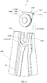
- FIG. 8 is a cross-sectional view of Variation 2 of the object moving device including the rigid portion-main body formed of the flat metal sheet.
- FIG.9 is a partial perspective view of Variation 2 of the same object moving device.
- Object moving device 1B illustrated in FIG. 8 and FIG. 9 has the same configuration as that of object moving device 1 except the configurations of attachment portion 420B and first direction-changing member 100B. Accordingly, only parts in object moving device 1B illustrated in FIG. 8 and FIG. 9 , which differ from the components of object moving device 1, will be described, and descriptions of the same components will be omitted by giving the same reference signs to the same names.
- rigid portion 130B unlike rigid portion 130, includes rigid portion-main body 132B that is a flat sheet.
- Rigid portion-main body 132B includes a through-hole formed in a central portion. Another end portion of support portion 120B is inserted into the through-hole from a side of a front surface onto a side of a rear surface of rigid portion-main body 132B.
- support portion 120B includes caulking portion 124 by being caulked on the side of the rear surface of rigid portion-main body 132B, and support portion 120B is fixed to rigid portion-main body 132B via caulking portion 124 described above.
- Caulking portion 124 protrudes on the side of the rear surface of rigid portion-main body 132B.
- the rear surface of rigid portion-main body 132B functions as planar portion 1321B abutting on abutting surface portion 426B.
- slit 426b opening on a side of the one direction is formed in abutting surface portion 426B within a peripheral wall portion that is second fitting portion 424.
- caulking portion 124 protruding on the side of the rear surface of rigid portion-main body 132B is disposed.
- the above configuration enables rigid portion-main body 132B to be disposed in a state of abutting on abutting surface portion 426B by disposition of caulking portion 124 within slit 426b when direction-changing member 100B is attached to attachment portion 420B, even in a configuration of rigid portion-main body 132B of direction-changing member 100B in which support portion 120B supporting direction-changing portion 110 is fixed to rigid portion-main body 132B via caulking portion 124 on a surface on a side opposite to a side on which support portion 120B is erected.
- the window regulator is exemplified as the object moving device according to the present invention
- the object moving device can be also applied to a device such as a walking assisting device as long as the device has a structure in which a drive section moves a movement object via a cable whose moving direction is changed by a direction-changing member.
Landscapes
- Window Of Vehicle (AREA)
Applications Claiming Priority (2)
| Application Number | Priority Date | Filing Date | Title |
|---|---|---|---|
| JP2018087464A JP2019190230A (ja) | 2018-04-27 | 2018-04-27 | 対象物移動装置 |
| PCT/JP2019/018224 WO2019208830A1 (ja) | 2018-04-27 | 2019-05-07 | 対象物移動装置 |
Publications (2)
| Publication Number | Publication Date |
|---|---|
| EP3786408A1 true EP3786408A1 (de) | 2021-03-03 |
| EP3786408A4 EP3786408A4 (de) | 2022-02-16 |
Family
ID=68294667
Family Applications (1)
| Application Number | Title | Priority Date | Filing Date |
|---|---|---|---|
| EP19792309.7A Withdrawn EP3786408A4 (de) | 2018-04-27 | 2019-05-07 | Objektbewegungsvorrichtung |
Country Status (3)
| Country | Link |
|---|---|
| EP (1) | EP3786408A4 (de) |
| JP (1) | JP2019190230A (de) |
| WO (1) | WO2019208830A1 (de) |
Families Citing this family (2)
| Publication number | Priority date | Publication date | Assignee | Title |
|---|---|---|---|---|
| JP7094258B2 (ja) * | 2019-10-24 | 2022-07-01 | 株式会社ハイレックスコーポレーション | 窓ガラス昇降装置 |
| CN114673424A (zh) * | 2022-04-08 | 2022-06-28 | 麦格纳汽车系统(苏州)有限公司 | 一种滚轮固定结构、车窗升降器及车辆 |
Family Cites Families (8)
| Publication number | Priority date | Publication date | Assignee | Title |
|---|---|---|---|---|
| JPH01131785U (de) * | 1988-02-29 | 1989-09-07 | ||
| US5657580A (en) * | 1995-09-29 | 1997-08-19 | Excel Industries, Inc. | Window regulator with spring actuated direct cable tensioning |
| US6227993B1 (en) * | 1998-12-21 | 2001-05-08 | Kuster & Co. Gmbh | Cable reversing system for an automatic window lift |
| JP3935820B2 (ja) * | 2002-10-29 | 2007-06-27 | 株式会社ハイレックスコ−ポレ−ション | ガイドプーリおよび該ガイドプーリを備えたウインドレギュレータ |
| JP6101449B2 (ja) * | 2012-08-24 | 2017-03-22 | 旭化成株式会社 | ワイヤ式ウインドウレギュレータ用ガイドレール |
| JP5944882B2 (ja) * | 2013-12-17 | 2016-07-05 | シロキ工業株式会社 | ウインドレギュレータ及びウインドレギュレータの製造方法 |
| US9580953B1 (en) * | 2016-02-03 | 2017-02-28 | Hi-Lex Controls, Inc. | Pulley joint assembly |
| JP6760800B2 (ja) * | 2016-08-26 | 2020-09-23 | 株式会社ハイレックスコーポレーション | 対象物移動装置およびこれを備える歩行支援装置 |
-
2018
- 2018-04-27 JP JP2018087464A patent/JP2019190230A/ja active Pending
-
2019
- 2019-05-07 WO PCT/JP2019/018224 patent/WO2019208830A1/ja not_active Ceased
- 2019-05-07 EP EP19792309.7A patent/EP3786408A4/de not_active Withdrawn
Also Published As
| Publication number | Publication date |
|---|---|
| EP3786408A4 (de) | 2022-02-16 |
| WO2019208830A1 (ja) | 2019-10-31 |
| JP2019190230A (ja) | 2019-10-31 |
Similar Documents
| Publication | Publication Date | Title |
|---|---|---|
| WO2002075090A1 (en) | Curved glass support structure and wind regulator | |
| US10927588B2 (en) | Window regulator | |
| US20200256111A1 (en) | Window regulator | |
| EP3786408A1 (de) | Objektbewegungsvorrichtung | |
| US11286704B2 (en) | Object moving device | |
| JP2025170085A (ja) | ウインドレギュレータ及びガイドレールの取付け方法 | |
| US6006473A (en) | Tape drive window regulator with universal housing for accommodating both manual and electric drive mechanisms | |
| CA2535272A1 (en) | Motorized sliding window pane | |
| JP6885897B2 (ja) | 対象物移動装置及び窓ガラス昇降装置 | |
| US11408217B2 (en) | Cable routing structure and window-glass lifting device using same | |
| US12083870B2 (en) | Carrier plate and object movement device | |
| US10975604B2 (en) | Window regulator | |
| JP2017039385A (ja) | ウインドレギュレータ及びウインドレギュレータの製造方法 | |
| US20200256104A1 (en) | Window regulator | |
| JP2001128350A (ja) | フラットケーブル巻取器 | |
| JP2007242283A (ja) | コネクタ取付装置 | |
| US11884140B2 (en) | Opening/closing body opening/closing device | |
| EP3533961A1 (de) | Objektbewegungsvorrichtung | |
| JP7706430B2 (ja) | 対象物移動装置およびウインドレギュレータ | |
| EP3533962A1 (de) | Objektbewegungsvorrichtung | |
| JP7233352B2 (ja) | 移動装置および窓ガラス昇降装置 | |
| JP3117510U (ja) | ウインドレギュレータ駆動部組立構造体 | |
| JP2022163832A (ja) | アウターケーシング取付構造及び対象物移動装置 | |
| JP6882952B2 (ja) | 移動装置 | |
| CN111051638A (zh) | 移动装置 |
Legal Events
| Date | Code | Title | Description |
|---|---|---|---|
| STAA | Information on the status of an ep patent application or granted ep patent |
Free format text: STATUS: THE INTERNATIONAL PUBLICATION HAS BEEN MADE |
|
| PUAI | Public reference made under article 153(3) epc to a published international application that has entered the european phase |
Free format text: ORIGINAL CODE: 0009012 |
|
| STAA | Information on the status of an ep patent application or granted ep patent |
Free format text: STATUS: REQUEST FOR EXAMINATION WAS MADE |
|
| 17P | Request for examination filed |
Effective date: 20201021 |
|
| AK | Designated contracting states |
Kind code of ref document: A1 Designated state(s): AL AT BE BG CH CY CZ DE DK EE ES FI FR GB GR HR HU IE IS IT LI LT LU LV MC MK MT NL NO PL PT RO RS SE SI SK SM TR |
|
| AX | Request for extension of the european patent |
Extension state: BA ME |
|
| DAV | Request for validation of the european patent (deleted) | ||
| DAX | Request for extension of the european patent (deleted) | ||
| A4 | Supplementary search report drawn up and despatched |
Effective date: 20220117 |
|
| RIC1 | Information provided on ipc code assigned before grant |
Ipc: E05F 15/689 20150101ALI20220111BHEP Ipc: B60J 1/17 20060101ALI20220111BHEP Ipc: E05F 11/48 20060101AFI20220111BHEP |
|
| STAA | Information on the status of an ep patent application or granted ep patent |
Free format text: STATUS: THE APPLICATION HAS BEEN WITHDRAWN |
|
| 18W | Application withdrawn |
Effective date: 20220225 |