EP3786032A1 - Instrumententafelträger für ein kraftfahrzeug - Google Patents
Instrumententafelträger für ein kraftfahrzeug Download PDFInfo
- Publication number
- EP3786032A1 EP3786032A1 EP20207000.9A EP20207000A EP3786032A1 EP 3786032 A1 EP3786032 A1 EP 3786032A1 EP 20207000 A EP20207000 A EP 20207000A EP 3786032 A1 EP3786032 A1 EP 3786032A1
- Authority
- EP
- European Patent Office
- Prior art keywords
- instrument panel
- section
- panel support
- cross member
- driver
- Prior art date
- Legal status (The legal status is an assumption and is not a legal conclusion. Google has not performed a legal analysis and makes no representation as to the accuracy of the status listed.)
- Granted
Links
Images












Classifications
-
- B—PERFORMING OPERATIONS; TRANSPORTING
- B62—LAND VEHICLES FOR TRAVELLING OTHERWISE THAN ON RAILS
- B62D—MOTOR VEHICLES; TRAILERS
- B62D25/00—Superstructure or monocoque structure sub-units; Parts or details thereof not otherwise provided for
- B62D25/08—Front or rear portions
- B62D25/14—Dashboards as superstructure sub-units
- B62D25/145—Dashboards as superstructure sub-units having a crossbeam incorporated therein
-
- B—PERFORMING OPERATIONS; TRANSPORTING
- B62—LAND VEHICLES FOR TRAVELLING OTHERWISE THAN ON RAILS
- B62D—MOTOR VEHICLES; TRAILERS
- B62D25/00—Superstructure or monocoque structure sub-units; Parts or details thereof not otherwise provided for
- B62D25/08—Front or rear portions
- B62D25/14—Dashboards as superstructure sub-units
- B62D25/145—Dashboards as superstructure sub-units having a crossbeam incorporated therein
- B62D25/147—Dashboards as superstructure sub-units having a crossbeam incorporated therein with adjustable connection to the A-pillars
-
- B—PERFORMING OPERATIONS; TRANSPORTING
- B62—LAND VEHICLES FOR TRAVELLING OTHERWISE THAN ON RAILS
- B62D—MOTOR VEHICLES; TRAILERS
- B62D27/00—Connections between superstructure or understructure sub-units
- B62D27/06—Connections between superstructure or understructure sub-units readily releasable
- B62D27/065—Connections between superstructure or understructure sub-units readily releasable using screwthread
Definitions
- the invention relates to an instrument panel support for a motor vehicle, which has a cross member that can be integrated between the A-pillars of a motor vehicle body.
- Instrument panel supports are used in motor vehicles as a load-bearing component for various cockpit functions.
- One of the main components of an instrument panel beam is the cross member.
- the cross member is part of the motor vehicle body and extends in the area below the windshield, running essentially horizontally and transversely between the A-pillars.
- the cross member has a longitudinal section on the driver's side and a longitudinal section on the passenger's side and is generally against the front wall, that is to say the partition wall between the engine compartment and the vehicle interior, as well as being additionally supported against the vehicle floor.
- the cross member has a stiffening effect on the motor vehicle body and is used to fasten the instrument panel, the cross member also having the task of stiffening the instrument panel itself.
- Various brackets are provided on the cross member to which the instrument panel and other functional vehicle components such as the steering column, heating and air conditioning system, airbag, center console, fuse box or glove compartment can be attached.
- the main forces from the steering column and the steering device, the weight force from the instrument panel and the support force on the steering from the driver are mainly transmitted to the cross member in the area of the driver's side.
- the loads on the cross member on the passenger side are usually lower.
- the crossbeams are usually produced with a profile cross-section that changes over the length of the crossbeam or are composed of length sections of different cross-sectional geometry.
- the length section on the driver's side has a larger profile cross-section than the length section on the passenger side.
- the crossbeam is matched to the locally acting forces, as a result of which the weight of the crossbeam is optimized.
- the cross section can be adapted to the structural space conditions in the front area of the motor vehicle body.
- the cross member is composed of individual length sections, the length sections having different cross sections from one another.
- the length sections are connected to one another by plastic deformation of a deformation section.
- The is concerned with the connection of the cross member of an instrument panel support to the side A-pillars EP 2 499 038 B1 .
- fastening openings for the implementation of elongated fastening members are formed directly through the tubular ends of the cross member.
- the cross member comprises means for attaching an end portion of the beam to an A-pillar.
- the fastening means are formed by a first opening and a second opening, the first opening being formed through the carrier itself and the second opening being formed through a separate fastening element joined to the end section.
- The also discloses an instrument panel support with a cross member WO 2005/090145 A1 .
- There cross members with different cross-sectional configurations and in particular differently configured end sections are disclosed.
- FIG FR 2 926 526 B1 A cross member with end sections running at right angles to the longitudinal extension of the cross member and having fastening openings is based on FIG FR 2 926 526 B1 emerged.
- FIG WO 2009/080968 A1 A cross member for an instrument panel carrier, in which the end sections are flattened and provided with fastening openings, is shown in FIG WO 2009/080968 A1 disclosed.
- the invention is based on the object of providing an instrument panel support that is technically improved in terms of components.
- One aspect of this task is to create a cross member for an instrument panel carrier with an advantageous connection to the A-pillars of a motor vehicle, the connection being modularly adaptable to different series of a motor vehicle.
- Another partial aspect of the task is to create a cross member for an instrument panel carrier which is designed to be load-appropriate and rigid in its longitudinal extension and which can be manufactured inexpensively and efficiently.
- Another aspect of the task is to optimize the weight of the cross member.
- top and bottom horizontal and vertical or longitudinal and transverse direction as well as top and bottom, driver's side, driver's side, passenger's side or passenger's side refer to the installation position of the cross member between the A-pillars within a motor vehicle body.
- a vehicle coordinate system is a three-dimensional Cartesian coordinate system used to identify the axes within a motor vehicle.
- the x-axis (vehicle longitudinal axis) is located in the vehicle longitudinal center plane and is horizontal to the front and directed in the direction of movement of the vehicle.
- the y-axis (vehicle transverse axis) is perpendicular to the vehicle longitudinal center plane and points transversely to the direction of movement of the vehicle.
- the z-axis (vertical axis of the vehicle) is perpendicular to the x-y plane of the vehicle and points with its positive direction upwards.
- the instrument panel support has a cross member that can be integrated between the A-pillars of a motor vehicle body.
- the cross member has a length section on the driver side and a length section on the passenger side.
- the longitudinal section on the driver's side and the longitudinal section on the passenger's side are preferably manufactured independently of one another and at an interface connected with each other.
- a mounting component is provided for attachment to an A-pillar.
- a mounting component that is the same or that is different from the mounting component at the driver-side end can be provided.
- the assembly component at the end of the cross member on the passenger side can also be formed from the tube of the cross member itself, for example by means of a flattening which is provided with assembly openings.
- the assembly components can be separate components each joined at one end of the cross member.
- a mounting component can also be formed by the end or an end section of the cross member itself.
- the assembly component can also be formed from the end of the cross member or the end section of the cross member, with an additional component being additionally provided which is joined to the end or end section of the cross member.
- the cut end section and the supplementary component joined to it together form the assembly component, which has appropriately arranged assembly openings for the passage of elongate fastening means, in particular assembly screws.
- assembly openings for the implementation of fastening means are provided, preferably in the vehicle longitudinal axis (x-axis).
- the passage of the fastening means can also run at an angle to the longitudinal direction of the vehicle.
- Optional reinforcement elements give the connection of the cross member to an A-pillar the necessary strength as well as longitudinal and transverse rigidity.
- An embodiment that is advantageous in practice provides that between the legs of the Mounting component is incorporated at least one reinforcing element supported on the legs.
- At least one assembly component is configured in a U-shape and has a web with two legs.
- each leg there are preferably at least two assembly openings arranged at a vertical distance from one another.
- the assembly openings are used for the implementation of elongated fastening means, in particular assembly screws.
- the mounting openings in the legs are preferably designed in the longitudinal direction of the vehicle (x-axis) for the fastening means to pass through.
- At least one reinforcing element supported on the legs is incorporated between the legs.
- connection of the cross member of an instrument panel carrier can be designed variably, in each case in adaptation to a series of a motor vehicle. This takes place in particular through the geometric design of the assembly component, preferably through the height and length or width of the legs and the height and / or length and / or width of the web and / or through the arrangement of the assembly opening and in particular through the distance between the assembly openings as well due to the arrangement of the assembly component itself relative to the adjacent end of the cross member, in particular in the z-axis.
- the legs of the assembly component can overlap the end of the crossbeam to compensate for tolerances.
- the assembly component can be joined, in particular welded, to the legs or to the web at the end of the cross member.
- a reinforcement element extends between a mounting opening in the first leg and a mounting opening in the second leg.
- a mounting opening in the first leg and a mounting opening in the second leg are arranged corresponding to one another and are preferably located in Vehicle longitudinal direction (x-axis) at the same height and have a common axis.
- the reinforcing element is supported on the inside on the two legs and is preferably joined to the legs.
- Positioning aids for a reinforcing element can be provided on the inside of the legs.
- a positioning aid can be formed, for example, by embossing the material.
- a reinforcing element is a sleeve or a support body configured to be U, V, S or Z-shaped in cross section.
- a reinforcing element encloses or at least partially encompasses the axis running in the x direction through the center points of the upper assembly openings or the lower assembly openings in the first front leg and in the second rear leg.
- the legs of the assembly component advantageously encompass the side sections of the end of the cross member.
- the assembly component is joined to the web at the end of the cross member.
- the legs are then directed outwards in the longitudinal direction of the cross member or the vehicle transverse axis (y-axis).
- An instrument panel support according to the invention is technically improved in terms of components and has a crossmember which can advantageously be connected to the respective A-pillar.
- the connection is modularly adaptable to different series of a motor vehicle.
- the cross member can be designed to be load-appropriate and rigid in the longitudinal direction or in its longitudinal extension.
- the wall thickness and cross-sectional geometry of the cross member are designed for the static and dynamic forces acting on it.
- the weight of the cross member is improved by saving material at less stressed points and by a cross-sectional design that is matched to the forces to be absorbed or acting in the motor vehicle.
- An advantageous embodiment of a mounting component provides that it is configured in a U-shape and has a web and two legs. In the legs, mutually corresponding assembly openings are provided for the implementation of an elongated fastening element.
- the assembly component has a cover leg on its top side and / or a bottom leg on its underside.
- the cover limb and / or the base limb are moved inwards from the web towards or into the limbs.
- the lid leg and the bottom leg ensure a further stiffening of the assembly component.
- the cover limb and / or the base limb can be joined to the side limbs of the assembly component in a materially bonded manner.
- the assembly component is made from a sheet metal blank, which corresponds to the development of the assembly component.
- the crossmember is at least on the driver's side on the A-pillar there by means of an assembly component set, wherein the mounting component is configured L-shaped and has a web and a leg.
- a reinforcement element is joined within the assembly component.
- the reinforcement element can be worked out in one piece from the web or a leg of the assembly component, for example by means of forming by means of embossing, edging and / or exhibitions.
- the reinforcement element has a passage for a fastening means. The passage is advantageously oriented in the longitudinal direction of the vehicle (x-axis).
- the assembly component prefferably configured in an I-shape.
- the assembly component can be designed at least in a length section by reshaping the tubular end section of the cross member, in particular by flattening the end section or a partial area of the end section.
- the front and rear vertical side wall areas of the end section are flattened and moved towards one another. Flattening does not mean that the side wall areas are against one another.
- the end section is configured approximately rectangular with a larger longitudinal axis than the transverse axis.
- a wall section of the end section of the cross member can be cut out.
- the rear leg of the end section of the cross member as seen from the interior of a motor vehicle, can be removed.
- An advantageous embodiment of an instrument panel support according to the invention provides a cross member in which assembly components according to the invention that are different from one another are provided at the driver-side end and at the passenger-side end of the cross member, for example a mounting component configured in a U-shape in the horizontal cross-section at the driver-side end of the cross member and one in the horizontal cross-section L. - or angled assembly component at the passenger-side end of the crossmember.
- the longitudinal section of the cross member on the driver's side can be composed of two shell components.
- the A-pillar-side end portion of the driver-side end portion is configured to be rectangular and has mounting openings.
- the mounting holes are for the passage of fasteners in Vehicle longitudinal direction (x-axis) configured.
- at least one reinforcing element supported between the side walls of the end section is incorporated in this end section.
- the driver-side length section has an end section which is composed of two shell components.
- basic modules of cross members can be provided, the length of which is designed by the end section for the respective model series or series of a motor vehicle.
- the end section formed from shell components has a rectangular configuration and has assembly openings for the passage of fastening means in the longitudinal direction of the vehicle (x-axis).
- at least one reinforcing element supported between side walls of the end section is incorporated.
- a cross member provides that the driver-side longitudinal section of the cross member is formed from a sheet metal blank, specifically by means of U-O shapes.
- a preform is first created by U-molding. Subsequently, the preform is reshaped into a three-dimensionally shaped closed tubular body (O-forms) which may run in a curved manner along its length. Butting edges of the sheet metal blank that make contact with one another or of the length section formed from the sheet metal blank are at least partially joined to one another in a materially bonded manner.
- At least the longitudinal section of the cross member on the driver's side can be divided in the vertical plane.
- driver-side longitudinal section of the cross member is divided in a horizontal plane.
- a rectangularly configured end of the longitudinal section of the cross member on the driver's side is preferred.
- the end can also have an oval cross-section.
- beads can be provided in the side walls of the end section of the cross member.
- the beads extend in particular in the vehicle transverse axis or the longitudinal direction of the cross member.
- a recess open towards the end of the cross member can be provided.
- An assembly component is inserted into the recess.
- the assembly component has assembly openings for the implementation of elongated fastening means in the vehicle's longitudinal axis (x-axis).
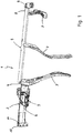
- the Figure 1 shows an instrument panel support in a perspective illustration.
- the instrument panel support has a cross member 1.
- the cross member 1 can be incorporated between A-pillars, not shown here, of a vehicle body and extends substantially horizontally across between the A-pillars.
- the cross member 1 consists of a driver-side longitudinal section 2 and a passenger-side longitudinal section 3, which are coupled to one another via a connecting component 4.
- the length section 3 on the passenger side is formed by a straight pipe.
- the length section 2 on the driver's side is formed by UO-shaping a sheet metal blank and has a varying cross-sectional profile over its longitudinal extent.
- the longitudinal section 2 on the driver's side has an approximately circular support section 6. Support struts 7 are also provided on the cross member 1.
- a mounting component 9 is joined to the end 8 of the cross member 1. This assembly component 9 is used to connect the cross member 1 to the A-pillar on the passenger side.
- a cross member 1 of the type in question has a longitudinal section 3 on the passenger side, which is as or similar to that in FIG Figure 1 is constructed and is coupled to the driver-side length section 2.
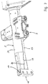
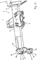
- connection of the cross member 1 to the A-pillar on the driver's side takes place via a mounting component 10, of which a first embodiment is based on the Figures 2 to 10 is explained.
- the assembly component 10 is configured in a U-shape and has a web 11 and two legs 12, 13.
- the end 14 of the length section 2 on the driver's side is configured to be essentially rectangular.
- the assembly component 10 is joined to the legs 12, 13 at the end 14 of the cross member 1.
- the legs 12, 13 grip over the vertically extending front side section 15 and the vertically extending rear side section 16 of the end 14, so that the assembly component 10 with the legs 12, 13 partially engages around the side sections 15, 16 of the end 14 and with the end 14 is joined.
- each leg 12, 13 mounting openings 17, 18, 19, 20 are provided one above the other and at a vertical distance a from one another.
- the upper assembly opening 17 in the first front leg 12 and the upper assembly opening 19 in the second rear leg 13 are at one level and on an axis.
- the lower assembly opening 18 in the first front leg 12 and the lower assembly opening 20 in the second rear leg 13 are at one level and on an axis.
- Reinforcing elements 21 are incorporated between the legs 12, 13. These are supported on the inner sides 22, 23 of the legs 12, 13.
- the reinforcement elements 21 are formed by U-shaped support bodies which are provided between the two upper assembly openings 17, 19 and between the two lower assembly openings 18, 20 of the assembly component 10.
- the open side of the U-shaped support body faces the web 11 of the assembly component 10.
- the assembly openings 17-20 and the reinforcement elements 21 are arranged in relation to one another that elongate fastening means, in particular assembly screws, pass through the assembly openings 17, 19 or 18, 20 and the sleeve-shaped or U-shaped reinforcement elements 21 in the longitudinal direction of the vehicle (x-axis). can be passed through.
- a fastening means runs parallel to the longitudinal extension of the reinforcement element 21 and is encompassed by the latter.
- the cross member 1 is fixed to the driver-side A-pillar of a motor vehicle via the mounting component 10 and the fastening means.
- the length section 2 of the cross member 1 on the driver's side as shown in FIG Figures 11 to 13 and 15 to 17 is formed by UO-forming a sheet metal blank. Butting edges 28, 29 of the length section 2 that contact one another are joined to one another at least in sections in a materially bonded manner.
- the upper side of the assembly component 10 terminates approximately flush with the upper side 30 of the longitudinal section 2 on the driver's side.
- the assembly component 10 projects in the z direction with respect to the underside 31 of the longitudinal section 2 on the driver's side.
- the legs 12, 13 as well as the web 11 of the assembly component 10 are configured in coordination with the cross-sectional geometry of the end 14 of the driver-side longitudinal section 2.
- the mounting position of the cross member 1 within the motor vehicle is determined via the length of the legs 12, 13 in the vehicle transverse axis (y-axis).
- the Figure 10 shows an embodiment of an assembly component 10, in which the legs 12, 13 each have a forward-facing changeover 32 on their free longitudinal edges directed towards the end 14 of the driver-side longitudinal section 2. In this way it can be achieved that the legs 12, 13 of the assembly component 10 extend in a vertical plane to the vertical wall sections of the end 14 or run in the vertical plane. Furthermore, the switch 32 can form a positioning aid or joining aid for the assembly component 10.
- the assembly component 10 is configured in a U-shape with a web 11 and two legs 12, 13.
- U-shaped reinforcing elements 21 extend between the legs 12, 13 and are located in the area of the assembly openings that are at the same level in the z-axis 17, 19 and 18, 20 are incorporated.
- the assembly component 10 is joined to the web 11 at the end 14 of the longitudinal section 2 of the cross member 1 on the driver's side.
- the legs 12, 13 are directed away from the end 14 of the driver-side length section 2 outwards in the y-axis.
- a receptacle 33 is formed which is configuratively adapted to the cross-sectional configuration of the rectangular end 14 of the longitudinal section 2 on the driver's side.
- the receptacle 33 has a circumferential collar 34 formed from the material of the assembly component 10.
- the mounting component 10 is plugged with the receptacle 33 onto the end 14 of the driver-side longitudinal section 2 and joined to it in a materially bonded manner.
- Such a configuration show the Figures 15 and 16 such as the Figure 18 .
- the end 14 of the longitudinal section 2 on the driver's side is inserted into the receptacle 33 and extends through it and is joined to the assembly component 10. This allows an advantageous setting of the position of the components, that is to say mounting component 10 and end 14, relative to one another.
- a rectangularly configured collarless receptacle 33 is provided in the web 11. At its longitudinal edges, the web 11 merges into the leg 12 or 13 via an arcuate transition section 35.
- FIG. 20 An L-shaped assembly component 36 is joined to the end 14 of the longitudinal section 2 on the driver's side in the apparent embodiment of an instrument panel support or its crossmember 1.
- the representation of the Figure 20 serves to illustrate the L-shape of the assembly component 36.
- the assembly component 36 has a web 37 and a leg 38.
- the mounting component 36 is joined to the web 37 on the end face at the end 14 of the cross member 1 or the longitudinal section 2 on the driver's side.
- assembly openings 39, 40 arranged one above the other are provided with a vertical spacing a.
- the mounting component 36 as in the Figure 21 As can be seen, it is configured in an L-shape with a web 37 and a leg 38.
- the mounting component 36 has a reinforcing element 41 formed in the mounting component 36, made of the same material and in one piece.
- the reinforcement element 41 is provided with a passage 42 for a fastening means.
- an additional support body 44 with an assembly opening 45 can be provided on the lower longitudinal section 43 of the assembly component 36.
- the Figures 22 to 24 as well as 25 and 26 show two configurations at the A-pillar end 14 of the driver-side longitudinal section 2 of the cross member 1.
- the end 14 is partially cut out and provided with a recess 46.
- a mounting component 47 is inserted into the outwardly open recess 46 and joined in a materially bonded manner.
- the assembly component 47 has assembly openings 48 Implementation of fasteners in the vehicle's longitudinal axis.
- the assembly openings 48 in the assembly component 47 correspond to assembly openings 49 in the end 14.
- the assembly component 47 combines the functions of assembly, guidance of the fastening means and reinforcement of the end 14.
- the mounting component 47 terminates with the upper wall section 50 and the lower wall section 51 of the end 14 of the longitudinal section 2.
- the mounting component 47 terminates essentially flush with the upper wall section 50 of the end 14 of the longitudinal section 2 on the driver's side.
- the mounting component 47 projects in the vertical direction with respect to the end 14.
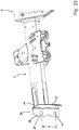
- the driver-side longitudinal section 2 is divided in a vertical plane and is formed from two shell components 24, 25. These abut one another in the longitudinal direction with abutting edges 26, 27 and are at least partially joined to one another along the abutting edges 26, 27.
- the A-pillar end 14 of the driver-side length section 2 is configured to be essentially rectangular in cross section.
- mounting openings 55, 56, 57, 58 are provided at a vertical distance above one another for the passage of fastening means in the longitudinal direction of the vehicle (x-axis).
- Reinforcing elements 61 are incorporated between the upper assembly openings 55, 57 in the first leg 59 and in the second leg 60 of the end section 54 and the lower assembly openings 56, 58 in the first leg 59 and in the second leg 60.
- the reinforcement elements 61 are configured in the shape of a sleeve or U and are supported on the inside of the legs 59, 60 of the end section 54.
- the reinforcement elements 61 are oriented in the x direction.
- the driver-side length section 2 as in the Figure 30 can be seen, has a support section 52 produced by UO molding, which extends to the A-pillar side Tapered towards the end of 14.
- An end section 62 is attached to the support section 52.
- This end section 62 consists of two shell components 63, 64 which are joined together.
- the end section 62 adjoins the support section 52 in the y direction.
- the end section 62 is configured to be rectangular and has mounting openings 55-58 for the passage of fastening means in the longitudinal direction of the vehicle (x-axis).
- Reinforcing elements 61 configured in a U-shape are incorporated in the end section 62. These each connect the upper assembly opening 55 in the first front leg 59 and the upper assembly opening 57 in the second rear leg 60 as well as the lower assembly opening 56 in the first front leg 59 and the lower assembly opening 58 in the second rear leg 60.
- the reinforcement elements 61 form a passage and extend in the direction of the x-axis, which leads through the mounting openings 55, 57 and 56, 58, respectively.
- FIG Figures 31 to 34 Various cross-sectional configurations of an end 14 or an end section 54 or 62 of the driver-side length section 2 are shown in FIG Figures 31 to 34 .
- the length section on the driver's side can be produced by UO-shaping a sheet metal blank. It is possible that the length section is formed by shell bodies.
- the driver-side length section 2 can be divided in a horizontal plane or a vertical plane.
- the end 14 on the A-pillar side or the end section 54 or 62 as shown in FIG Figures 31 and 32 is configured approximately D-shaped with a radius R1 at the transition from the upper side to the front side and a radius R2 running with a larger radius at the transition between the front side wall and the lower side.
- the end 14 and the end portion 54, 62, as in FIG Figure 33 can be seen, is configured approximately oval in cross section.
- beads 65 extending in the longitudinal direction are provided in the upper wall section and in the lower wall section.
- the length section 2 is configured from a U-profile or a hat profile. Assembly components according to the invention for connecting the cross member to an A-pillar are not visible here.
- a mounting component is provided at the driver-side end 2 of the cross member 1, which is configured in a U-shape with a web and two legs. At least two assembly openings are provided in the legs at a vertical distance from one another, with at least one reinforcing element supported on the legs being incorporated between the legs.
- the end section 66 of the driver-side length section 2 is cut out in some areas.
- a mounting component 68 is inserted into the recess 67 which is open towards the end 14 of the cross member 1.
- assembly openings 69 with reinforcing elements 70 integrated in between are provided.
- FIG. 36 and 37 show a recess 67 in the area of the front side wall 71 of the end section 66 is in the embodiment according to the illustration of FIG Figures 38 and 39 a region of the upper side 72 and the front side wall 73 and the rear side wall 74 of the end section 66 cleared by a recess 67 and closed by a mounting component 68.
- FIG 40 shows the driver-side longitudinal section 2 of a cross member 1, at the end 14 of which a U-shaped assembly component 10 is attached.
- the assembly component 10 has a web 11 and two legs 12, 13.
- the mounting component 10 is attached with the web 11 on the front side in front of the end 14 of the driver-side longitudinal section 2 and is joined to the end 14 in a materially bonded manner.
- Two assembly openings 17-20 are provided in each leg 12, 13 at a vertical distance one above the other. Reinforcing elements that are not visible here and are supported on the inner sides of the legs 12, 13 are incorporated between the legs 12, 13.
- the Figure 41 shows a further embodiment of an instrument panel support and its transverse support 1.
- the transverse support 1 has a longitudinal section 2 on the driver's side and a longitudinal section 3 on the passenger's side. These are coupled to one another via a connecting component 4.
- the longitudinal section 3 on the passenger side is essentially formed by a straight pipe.
- a mounting component 9 is joined to the end 8 of the cross member 1.
- the assembly component 9 is configured in an L-shape and has a web 37 and a leg 38.
- a reinforcing element 41 which has a passage 42 for a fastening means, is joined to the mounting component 9.
- the Figure 42 shows the longitudinal section 2 of the cross member 1 on the driver's side.
- the Figure 43 shows the end section or the end 14 of the longitudinal section 2 on the driver's side.
- a mounting component 10 is joined at the end 14.
- the mounting component 10 is configured in a U-shape in horizontal cross section and has a web 11 and two legs 12, 13.
- the configuration corresponds to the design of the mounting component 10, as shown in FIG Figures 2 to 6 described. Reference is made to the corresponding explanations.
- each leg 12, 13 mounting openings 17, 19 and 18, 20 are provided one above the other and at a vertical distance.
- the assembly openings 17, 19 and 18, 20 located at one level correspond to one another and are designed to pass through an elongate fastening element, in particular an assembly screw.
- Reinforcing elements 21 are also incorporated, which extend between the legs 12, 13 and are supported on them.
- the reinforcement elements 21 are advantageous, but not mandatory.
- a mounting component 10 can consequently also be designed without reinforcing elements.
- the mounting component 10 as in the Figures 41 to 44 shown, has on its top side 75 a cover leg 76 formed by a fold.
- the cover leg 76 covers the top side 75 of the assembly component 10 and engages over the end 14 of the driver-side longitudinal section 2 of the cross member 1.
- the cover limb 76 and the limbs 12, 13 of the assembly component 10, which run vertically in the z-axis, can be joined to one another in a materially bonded manner.
- the assembly component 10 has a bottom leg on its underside 77.
- the bottom leg is designed in the same way as the cover leg 76 on the upper side 75 of the assembly component 10.
- the mounting component 10 as shown in FIG Figures 41 to 44 , as well as the mounting component 10, as in the Figures 1 to 19 shown and explained, is made from a sheet metal blank, which corresponds to the development of the assembly component.
- the sheet metal blank is machined accordingly, so that the U-shaped configuration with web 11 and legs 12, 13 and optionally with a cover leg 76 on the top 75 and / or a bottom leg on the underside 77 results.
- the driver-side longitudinal section 2 of the cross member 1 is divided in a horizontal longitudinal plane and made of two shell components. It is also possible for the length section 2 on the driver's side to be produced by UO-shaping a sheet metal blank. Furthermore, the length section 2 on the driver's side can also be formed by hydroforming.
Landscapes
- Engineering & Computer Science (AREA)
- Chemical & Material Sciences (AREA)
- Combustion & Propulsion (AREA)
- Transportation (AREA)
- Mechanical Engineering (AREA)
- Body Structure For Vehicles (AREA)
Abstract
Description
- Die Erfindung betrifft einen Instrumententafelträger für ein Kraftfahrzeug, der einen zwischen den A-Säulen einer Kraftfahrzeugkarosserie eingliederbaren Querträger aufweist.
- Instrumententafelträger werden in Kraftfahrzeugen als tragendes Bauteil für diverse Cockpit-Funktionen eingesetzt. Eine der Hauptkomponenten eines Instrumententafelträgers ist der Querträger. Der Querträger ist Teil der Kraftfahrzeugkarosserie und erstreckt sich im Bereich unterhalb der Windschutzscheibe im Wesentlichen horizontal verlaufend quer zwischen den A-Säulen. Der Querträger weist einen fahrerseitigen Längenabschnitt und einen beifahrerseitigen Längenabschnitt auf und ist in der Regel gegen die Stirnwand, also die Trennwand zwischen Motorraum und Fahrzeuginnenraum, sowie gegen den Fahrzeugboden hin zusätzlich abgestützt.
- Der Querträger hat eine versteifende Wirkung auf die Kraftfahrzeugkarosserie und dient zur Befestigung der Instrumententafel, wobei dem Querträger außerdem die Aufgabe zukommt, die Instrumententafel selbst auszusteifen. An dem Querträger sind diverse Halterungen vorgesehen, an denen die Instrumententafel sowie weitere Fahrzeugfunktionskomponenten wie die Lenksäule, Heizungs- und Klimaanlage, Airbag, Mittelkonsole, Sicherungskasten oder Handschuhfach befestigt werden.
- Die Hauptkräfte durch die Lenksäule und die Lenkeinrichtung, die Gewichtskraft durch die Instrumententafel sowie die Abstützkraft an der Lenkung durch den Fahrer werden hauptsächlich im Bereich der Fahrerseite auf den Querträger übertragen. Die Belastungen des Querträgers auf der Beifahrerseite sind üblicherweise geringer. Daher werden die Querträger regelmäßig mit einem sich über die Länge des Querträgers ändernden Profilquerschnitt hergestellt oder aus Längenabschnitten unterschiedlicher Querschnittsgeometrie zusammengesetzt. Den Kräfteverhältnissen entsprechend weist der Längenabschnitt auf der Fahrerseite einen größeren Profilquerschnitt auf als der Längenabschnitt auf der Beifahrerseite. Durch eine derartige Querschnitts- bzw. Durchmesseranpassung wird der Querträger auf die lokal einwirkenden Kräfte abgestimmt, wodurch eine Gewichtsoptimierung des Querträgers erreicht wird. Zudem kann in gewissem Maße eine Anpassung des Querschnitts an die Bauraumverhältnisse im vorderen Bereich der Kraftfahrzeugkarosserie vorgenommen werden.
- Bei der aus der
US 6,817,382 B2 bekannten Ausführungsform ist der Querträger aus einzelnen Längenabschnitten zusammengesetzt, wobei die Längenabschnitte voneinander verschiedene Querschnitte besitzen. Die Längenabschnitte sind durch plastische Verformung eines Verformungsabschnitts miteinander verbunden. - Auch die aus der
DE 101 21 402 A1 oder derEP 1 655 208 A1 bekannten Querträger von Instrumententafelstrukturen weisen Längenabschnitte mit unterschiedlichen Querschnittskonfigurationen auf, die über Verbindungsbauteile miteinander gefügt sind. - Mit der Anbindung des Querträgers eines Instrumententafelträgers an den seitlichen A-Säulen befasst sich die
EP 2 499 038 B1 . Dort sind Befestigungsöffnungen zur Durchführung von länglichen Befestigungsorganen unmittelbar durch die rohrförmig gestalteten Enden des Querträgers hindurch ausgebildet. - Bei dem aus der
EP 2 542 462 B1 bekannten Vorschlag umfasst der Querträger Mittel zur Befestigung eines Endabschnitts des Trägers an einer A-Säule. Die Befestigungsmittel sind durch eine erste Öffnung und eine zweite Öffnung gebildet, wobei die erste Öffnung durch den Träger selbst hindurch ausgebildet ist und die zweite Öffnung durch ein separates am Endabschnitt gefügtes Befestigungselement hindurch ausgebildet ist. - Solche Vorschläge sind auch durch die
DE 10 2005 004 605 B4 vorbekannt. - Einen Instrumententafelträger mit einem Querträger offenbart auch die
WO 2005/090145 A1 . Dort sind Querträger mit unterschiedlichen Querschnittskonfigurationen und insbesondere unterschiedlich konfigurierten Endabschnitten offenbart. - Ein Querträger mit rechtwinklig zur Längserstreckung des Querträgers verlaufenden Endabschnitten, die Befestigungsöffnungen aufweisen, geht aus der
FR 2 926 526 B1 - Einen Querträger für einen Instrumententafelträger, bei dem die Endabschnitte abgeflacht und mit Befestigungsöffnungen versehen sind, ist in der
WO 2009/080968 A1 offenbart. - Der Erfindung liegt ausgehend vom Stand der Technik die Aufgabe zugrunde, einen bauteiltechnisch verbesserten Instrumententafelträger aufzuzeigen.
- Ein Teilaspekt dieser Aufgabe besteht darin, einen Querträger für einen Instrumententafelträger zu schaffen mit einer vorteilhaften Anbindung an die A-Säulen eines Kraftfahrzeugs, wobei die Anbindung modular an verschiedene Baureihen eines Kraftfahrzeugs anpassbar ist.
- Ein weiterer Teilaspekt der Aufgabe besteht darin, einen Querträger für einen Instrumententafelträger zu schaffen, der in seiner Längserstreckung belastungsgerecht und biegesteif ausgelegt ist sowie kostengünstig und rationell herstellbar ist.
- Ein weiterer Teilaspekt der Aufgabe besteht darin, den Querträger gewichtsmäßig zu optimieren.
- Selbstständige Lösungen dieser Aufgabe bzw. der Teilaspekte der erfindungsgemäßen Aufgabe zeigen die Instrumententafelträger gemäß der unabhängigen Ansprüche auf.
- Vorteilhafte Ausgestaltungen und Weiterbildungen der Erfindung sind Gegenstand der abhängigen Ansprüche.
- Begriffe wie oben und unten, horizontal und vertikal oder Längsrichtung und Querrichtung sowie Oberseite und Unterseite, Fahrerseite, fahrerseitig, Beifahrerseite oder beifahrerseitig beziehen sich auf die Einbaulage des Querträgers zwischen den A-Säulen innerhalb einer Kraftfahrzeugkarosserie.
- Ein Fahrzeugkoordinatensystem ist ein dreidimensionales kartesisches Koordinatensystem, um die Achsen innerhalb eines Kraftfahrzeugs zu kennzeichnen. Die x- und y-Achse liegen in einer Horizontalebene (= Fahrbahnebene). Die x-Achse (Fahrzeuglängsachse) befindet sich in der Fahrzeuglängsmittelebene und ist nach vorne waagerecht und in Bewegungsrichtung des Fahrzeugs gerichtet. Die y-Achse (Fahrzeugquerachse) steht senkrecht auf der Fahrzeuglängsmittelebene und zeigt quer zur Bewegungsrichtung des Fahrzeugs. Die z-Achse (Fahrzeughochachse) steht senkrecht auf der x-y-Ebene des Fahrzeugs und zeigt mit ihrer positiven Richtung nach oben.
- Der Instrumententafelträger weist einen zwischen den A-Säulen einer Kraftfahrzeugkarosserie eingliederbaren Querträger auf. Der Querträger besitzt einen fahrerseitigen Längenabschnitt und einen beifahrerseitigen Längenabschnitt. Vorzugsweise sind der fahrerseitige Längenabschnitt und der beifahrerseitige Längenabschnitt voneinander unabhängig gefertigt und an einer Schnittstelle miteinander verbunden. Wenigstend am fahrerseitigen Ende des Querträgers ist ein Montagebauteil zur Befestigung an eine A-Säule vorgesehen.
- Am beifahrerseitigen Ende des Querträgers kann ein gleiches oder vom Montagebauteil am fahrerseitigen Ende verschiedenes Montagebauteil vorgesehen sein. Das Montagebauteil am beifahrerseitigen Ende des Querträgers kann auch aus dem Rohr des Querträgers selbst ausgebildet sein, beispielsweise durch eine Abplattung, die mit Montageöffnungen versehen ist.
- Die Montagebauteile können separate jeweils an einem Ende des Querträgers gefügte Bauteile sein. Ein Montagebauteil kann auch durch das Ende bzw. einen Endabschnitt des Querträgers selbst gebildet sein. Weiterhin ist es möglich, die Anbindung des Querträgers an eine A-Säule durch eine Konfiguration der Endabschnitte in der Kombination mit in die Endabschnitte ein- bzw. angesetzte Montagebauteile zu gestalten. Hierzu ist der Endabschnitt eines Querträgers partiell ausgeschnitten. In diese Aussparung ist ein Montagebauteil eingesetzt.
- Das Montagebauteil kann auch aus dem Ende des Querträgers bzw. dem Endabschnitt des Querträgers gebildet sein, wobei zusätzlich ein Ergänzungsbauteil vorgesehen ist, welches mit dem Ende bzw. Endabschnitt des Querträgers gefügt ist. Der zugeschnittene Endabschnitt und das an diesem gefügte Ergänzungsbauteil bilden gemeinsam das Montagebauteil, welches zweckentsprechend angeordnete Montageöffnungen zur Durchführung von länglichen Befestigungsmitteln, insbesondere Montageschrauben, aufweist.
- Im Montagebauteil ebenso wie in dem mit dem Montagebauteil zusammenwirkenden Endabschnitt des Querträgers sind Montageöffnungen zur Durchführung von Befestigungsmitteln vorzugsweise in Fahrzeuglängsachse (x-Achse) vorgesehen. Grundsätzlich kann der Durchgang der Befestigungsmittel auch in einem Winkel zur Fahrzeuglängsrichtung verlaufen.
- Optionale Verstärkungselemente verleihen der Anbindung des Querträgers an eine A-Säule die notwendige Festigkeit sowie Längs- und Quersteifigkeit. Eine für die Praxis vorteilhafte Ausgestaltung sieht vor, dass zwischen die Schenkel des Montagebauteils zumindest ein sich an den Schenkeln abstützendes Verstärkungselement eingegliedert ist.
- Bei einem für die Praxis besonders vorteilhaften Instrumententafelträger ist zumindest ein Montagebauteil U-förmig konfiguriert und weist einen Steg mit zwei Schenkeln auf. In jedem Schenkel sind vorzugsweise zumindest zwei mit vertikalem Abstand zueinander angeordnete Montageöffnungen vorgesehen. Die Montageöffnungen dienen zur Durchführung von länglichen Befestigungsmitteln, insbesondere Montageschrauben. Die Montageöffnungen in den Schenkeln sind zum Durchgang der Befestigungsmittel vorzugsweise in Fahrzeuglängsrichtung (x-Achse) ausgebildet.
- Zwischen den Schenkeln ist zumindest ein sich an den Schenkeln abstützendes Verstärkungselement eingegliedert.
- Mittels des U-förmig konfigurierten Montagebauteils kann die Anbindung des Querträgers eines Instrumententafelträgers variabel gestaltet werden jeweils in Anpassung an eine Baureihe eines Kraftfahrzeugs. Dies erfolgt insbesondere durch die geometrische Auslegung des Montagebauteils, vorzugsweise durch die Höhe und die Länge oder Breite der Schenkel und der Höhe und/oder Länge und/oder Breite des Stegs und/oder durch die Anordnung der Montageöffnung und insbesondere durch Abstand zwischen den Montageöffnungen sowie durch die Anordnung des Montagebauteils selbst relativ zum benachbarten Ende des Querträgers, insbesondere in z-Achse.
- Besonders vorteilhaft können die Schenkel des Montagebauteils das Ende des Querträgers toleranzausgleichend überlappen.
- Das Montagebauteil kann mit den Schenkeln oder mit dem Steg am Ende des Querträgers gefügt, insbesondere geschweißt sein.
- Ein Verstärkungselement erstreckt sich zwischen einer Montageöffnung im ersten Schenkel und einer Montageöffnung im zweiten Schenkel. Eine Montageöffnung im ersten Schenkel und eine Montageöffnung im zweiten Schenkel sind korrespondierend zueinander angeordnet und liegen vorzugsweise in Fahrzeuglängsrichtung (x-Achse) auf einer Höhe und haben eine gemeinsame Achse. Das Verstärkungselement stützt sich jeweils innenseitig an den beiden Schenkeln ab und ist vorzugsweise mit den Schenkeln gefügt. An den Innenseiten der Schenkel können Positionierhilfen für ein Verstärkungselement vorgesehen sein. Eine Positionierhilfe kann beispielsweise durch eine Materialverprägung ausgebildet sein.
- Besonders vorteilhaft ist ein Verstärkungselement eine Hülse oder ein im Querschnitt U-, V-, S- oder Z-förmig konfigurierter Stützkörper. Ein Verstärkungselement umschließt bzw. umgreift zumindest teilweise die sich jeweils in x-Richtung durch die Mittelpunkte der oberen Montageöffnungen bzw. der unteren Montageöffnungen im ersten vorderen Schenkel und im zweiten hinteren Schenkel verlaufende Achse.
- Vorteilhafterweise umgreift das Montagebauteil mit den Schenkeln die Seitenabschnitte des Endes des Querträgers.
- Möglich ist es auch, dass das Montagebauteil mit dem Steg am Ende des Querträgers gefügt ist. Die Schenkel sind dann in Längsrichtung des Querträgers bzw. der Fahrzeugquerachse (y-Achse) nach außen gerichtet.
- Gemäß anderer Ausführungsformen und Modifikationen umfasst der Instrumententafelträger eines oder mehrere der folgenden Merkmale, welche alleine oder in technisch vorteilhafter Kombination vorgesehen sind:
- ein Montagebauteil ist U-förmig konfiguriert mit einem Steg und zwei Schenkeln;
- ein U-förmig konfiguriertes Montagebauteil weist oberseitig einen Deckelschenkel und/oder unterseitig einen Bodenschenkel auf;
- das Verstärkungselement ist eine Hülse;
- das Verstärkungselement ist ein im Querschnitt U-, V-, S- oder Z-förmig konfigurierter Stützkörper;
- das Montagebauteil ist mit den Schenkeln am Ende des Querträgers gefügt;
- das Montagebauteil umgreift mit den Schenkeln Seitenabschnitte des Endes des Querträgers;
- das Montagebauteil ist mit dem Steg am Endes des Querträgers gefügt;
- das Montagebauteil ist L-förmig konfiguriert;
- ein Verstärkungselement ist materialeinheitlich und einstückig im Montagebauteil ausgebildet und weist einen Durchgang für ein Befestigungsmittel in Fahrzeuglängsrichtung (x-Achse) auf;
- ein A-säulenseitiger Endabschnitt, insbesondere der fahrerseitige Endabschnitt des Querträgers ist rechteckig konfiguriert;
- in einem oder jedem Endabschnitt des Querträgers sind Montageöffnungen für den Durchgang von Befestigungsmitteln in Fahrzeuglängsrichtung (x-Achse) vorgesehen;
- der fahrerseitige Längenabschnitt des Querträgers ist durch U-O-Formen eines Blechzuschnitts geformt;
- in Längsrichtung des fahrerseitigen Längenabschnitts des Querträgers einander kontaktierende Stoßkanten sind zumindest bereichsweise miteinander stoffschlüssig gefügt;
- der fahrerseitige Längenabschnitt des Querträgers ist aus Schalenbauteilen gebildet, insbesondere aus zwei Halbschalen;
- der fahrerseitige Längenabschnitt weist einen Endabschnitt auf, welcher aus zwei Schalenbauteilen zusammengesetzt ist;
- der fahrerseitige Längenabschnitt des Querträgers weist Abschnitte mit voneinander verschiedenen Wandstärken auf;
- der fahrerseitige Längenabschnitt des Querträgers weist Abschnitte mit voneinander verschiedenen Durchmessern auf;
- der fahrerseitige Endabschnitt des Querträgers weist eine Aussparung auf, in welche ein Montagebauteil oder ein Ergänzungsbauteil eingesetzt ist;
- der Querträger oder ein Längenabschnitt des Querträgers ist durch Innenhochdruckumformung geformt.
- Ein erfindungsgemäßer Instrumententafelträger ist bauteiltechnisch verbessert und weist einen Querträger auf, der vorteilhaft an die jeweilige A-Säule angebunden werden kann. Die Anbindung ist modular an verschiedene Baureihen eines Kraftfahrzeugs anpassbar. Weiterhin ist der Querträger in Längsrichtung bzw. in seiner Längserstreckung belastungsgerecht und biegesteif auslegbar. Wandstärke und Querschnittsgeometrie des Querträgers sind auf die einwirkenden statischen und dynamischen Kräfte ausgelegt. Weiterhin ist der Querträger gewichtsmäßig verbessert durch Einsparung von Material an weniger belasteten Stellen sowie durch eine Querschnittsgestaltung abgestimmt auf die im Kraftfahrzeug aufzunehmenden bzw. einwirkenden Kräfte.
- Eine vorteilhafte Ausgestaltung eines Montagebauteils sieht vor, dass dieses U-förmig konfiguriert ist und einen Steg sowie zwei Schenkel aufweist. In den Schenkeln sind zueinander korrespondierende Montageöffnungen zur Durchführung eines länglichen Befestigungselements vorgesehen.
- Bei einer Ausgestaltung dieser Konfiguration weist das Montagebauteil an seiner Oberseite einen Deckelschenkel und/oder an seiner Unterseite einen Bodenschenkel auf. Der Deckelschenkel und/oder der Bodenschenkel sind ausgehend vom Steg nach innen in Richtung auf bzw. in die Schenkel umgestellt. Der Deckelschenkel und der Bodenschenkel gewährleisten eine weitere Versteifung des Montagebauteils. Zusätzlich können der Deckelschenkel und/oder der Bodenschenkel mit den seitlichen Schenkeln des Montagebauteils stoffschlüssig gefügt sein.
- Das Montagebauteil ist aus einem Blechzuschnitt hergestellt, welches der Abwicklung des Montagebauteils entspricht.
- Bei einer Ausführungsform des Instrumententafelträgers ist der Querträger zumindest auf der Fahrerseite an der dortigen A-Säule mittels eines Montagebauteils festgelegt, wobei das Montagebauteil L-förmig konfiguriert ist und einen Steg und einen Schenkel aufweist. Innerhalb des Montagebauteils ist ein Verstärkungselement gefügt. Das Verstärkungselement kann einstückig aus dem Steg oder einem Schenkel des Montagebauteils herausgearbeitet sein, beispielsweise umformtechnisch durch Einprägungen, Umkantungen und/oder Ausstellungen. Das Verstärkungselement weist einen Durchgang für ein Befestigungsmittel auf. Der Durchgang ist vorteilhafterweise in Fahrzeuglängsrichtung (x-Achse) orientiert.
- Grundsätzlich ist es möglich, dass das Montagebauteil I-förmig konfiguriert ist.
- Weiterhin kann das Montagebauteil zumindest in einem Längenabschnitt durch Umformung des rohrförmigen Endabschnitts des Querträgers gestaltet sein, insbesondere durch eine Abplattung des Endabschnitts oder eines partiellen Bereichs des Endabschnitts. Bei einer Abplattung sind die vorderen und hinteren vertikalen Seitenwandbereiche des Endabschnitts abgeflacht und aufeinander zu bewegt. Eine Abplattung bedeutet nicht, dass die Seitenwandbereiche aneinander liegen. Im vertikalen Querschnitt ist der Endabschnitt in etwa rechteckig konfiguriert mit einer größeren Längsachse als Querachse.
- Weiterhin kann ein Wandabschnitt des Endabschnitts des Querträgers ausgeschnitten sein. Insbesondere kann der vom Innenraum eines Kraftfahrzeugs aus gesehen hintere Schenkel des Endabschnitts des Querträgers entfernt sein.
- Eine vorteilhafte Ausgestaltung eines erfindungsgemäßen Instrumententafelträgers sieht einen Querträger vor, bei dem am fahrerseitigen Ende und am beifahrerseitigen Ende des Querträgers voneinander verschiedene erfindungsgemäße Montagebauteile vorgesehen sind, beispielsweise ein im horizontalen Querschnitt U-förmig konfiguriertes Montagebauteil am fahrerseitigen Ende des Querträgers und ein im horizontalen Querschnitt L- bzw. winkelförmiges Montagebauteil am beifahrerseitigen Ende des Querträgers.
- Der fahrerseitige Längenabschnitt des Querträgers kann aus zwei Schalenbauteilen zusammengesetzt sein. Der A-säulenseitige Endabschnitt des fahrerseitigen Endabschnitts ist rechteckig konfiguriert und weist Montageöffnungen auf. Die Montageöffnungen sind für den Durchgang von Befestigungsmitteln in Fahrzeuglängsrichtung (x-Achse) konfiguriert. Weiterhin ist in diesem Endabschnitt zumindest ein sich zwischen den Seitenwänden des Endabschnitts abstützendes Verstärkungselement eingegliedert.
- Eine weitere Alternative sieht vor, dass der fahrerseitige Längenabschnitt einen Endabschnitt aufweist, welcher aus zwei Schalenbauteilen zusammengesetzt ist. Auf diese Weise können Grundmodule von Querträgern bereitgestellt werden, die in ihrer Länge durch den Endabschnitt auf die jeweilige Modellreihe bzw. Baureihe eines Kraftfahrzeugs ausgelegt werden. Gleiches gilt für die Anbindung an die A-Säulen. Der aus Schalenbauteilen gebildete Endabschnitt ist rechteckig konfiguriert und weist Montageöffnungen für den Durchgang von Befestigungsmitteln in Fahrzeuglängsrichtung (x-Achse) auf. Im Endabschnitt ist zumindest ein sich zwischen Seitenwänden des Endabschnitts abstützendes Verstärkungselement eingegliedert.
- Eine vorteilhafte Ausführungsform eines Querträgers sieht vor, dass der fahrerseitige Längenabschnitt des Querträgers aus einem Blechzuschnitt geformt ist und zwar mittels U-O-Formen. Hierbei wird zunächst eine Vorform durch das U-Formen erzeugt. Anschließend wird die Vorform zu einem dreidimensional geformten, gegebenenfalls in seine Längserstreckung gekrümmt verlaufenden geschlossenen Rohrkörper (O-Formen) umgeformt. Einander kontaktierende Stoßkanten des Blechzuschnitts bzw. des aus dem Blechzuschnitt geformten Längenabschnitts werden zumindest partiell stoffschlüssig miteinander gefügt.
- Zumindest der fahrerseitige Längenabschnitt des Querträgers kann in Vertikalebene geteilt sein.
- Möglich ist es auch, dass der fahrerseitige Längenabschnitt des Querträgers in einer Horizontalebene geteilt ist.
- Bevorzugt ist ein rechteckig konfiguriertes Ende des fahrerseitigen Längenabschnitts des Querträgers.
- Grundsätzlich kann das Ende auch einen oval konfigurierten Querschnitt besitzen.
- Weiterhin können Sicken in den Seitenwänden des Endabschnitts des Querträgers vorgesehen sein. Die Sicken erstrecken sich insbesondere in Fahrzeugquerachse bzw. Längsrichtung des Querträgers.
- Weiterhin kann zumindest in einer Seitenwand des A-säulenseitigen Endabschnitts des fahrerseitigen Längenabschnitts des Querträgers eine zum Ende des Querträgers hin offene Aussparung vorgesehen sein. In die Aussparung ist ein Montagebauteil eingesetzt. Das Montagebauteil weist Montageöffnungen zur Durchführung von länglichen Befestigungsmitteln in Fahrzeuglängsachse (x-Achse) auf.
- Ausführungsformen der Erfindung sowie erfindungsgemäße Aspekte sind in den nachfolgenden Zeichnungen beschrieben. Es zeigen:
- Figur 1
- einen erfindungsgemäßen Instrumententafelträger in einer Perspektive;
- Figur 2
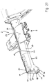
- den fahrerseitigen Längenabschnitt eines Instrumententafelträgers in einer Perspektive;
- Figur 3
- die Darstellung gemäß der
Figur 2 in einer Draufsicht; - Figur 4
- die Darstellung gemäß der
Figur 2 in einer Seitenansicht; - Figur 5
- den Endabschnitt des Querträgers mit dem Montagebauteil zur Anbindung an eine A-Säule;
- Figur 6
- das Montagebauteil entsprechend der Darstellung der
Figur 5 aus einer anderen Perspektive; - Figur 7
- eine weitere Ausführungsform eines Instrumententafelträgers mit der Darstellung des fahrerseitigen Längenabschnitts eines Querträgers in einer perspektivischen Darstellungsweise;
- Figur 8
- die Darstellung entsprechend der
Figur 7 in einer Draufsicht; - Figur 9
- die Darstellung entsprechend der
Figur 7 in einer Seitenansicht; - Figur 10
- das endseitige Montagebauteil des Querträgers entsprechend der Darstellung von
Figur 7 ; - Figur 11
- eine weitere Ausführungsform eines Instrumententafelträgers mit der Darstellung des fahrerseitigen Längenabschnitts des Querträgers in einer Perspektive;
- Figur 12
- die Darstellung entsprechend der
Figur 11 in einer Draufsicht; - Figur 13
- die Darstellung entsprechend der
Figur 11 in einer Seitenansicht; - Figur 14
- ein Montagebauteil zur Festlegung eines Instrumententafelträgers bzw. dessen Querträgers an eine A-Säule in einer perspektivischen Darstellung;
- Figur 15
- eine weitere Ausführungsform eines Instrumententafelträgers mit der Darstellung des fahrerseitigen Längenabschnitts eines Querträger in einer Perspektive;
- Figur 16
- die Darstellung entsprechend der
Figur 15 in einer Draufsicht; - Figur 17
- die Darstellung entsprechend der
Figur 15 in einer Seitenansicht; - Figur 18
- das Montagebauteil des Instrumententafelträgers in einer Perspektive;
- Figur 19
- das Montagebauteil entsprechend der Darstellung von
Figur 15 in einer anderen Perspektive; - Figur 20
- eine weitere Ausführungsform eines Instrumententafelträgers mit der Darstellung des fahrerseitigen Längenabschnitts des Querträgers in einer Perspektive;
- Figur 21
- eine weitere Ausführungsform eines Instrumententafelträgers mit der Darstellung des fahrerseitigen Längenabschnitts des Querträgers in einer Perspektive;
- Figur 22
- eine weitere Ausführungsform eines Instrumententafelträgers mit der Darstellung des fahrerseitigen Längenabschnitts des Querträgers in einer Draufsicht;
- Figur 23
- die Darstellung entsprechend der
Figur 22 in einer Seitenansicht; - Figur 24
- einen Schnitt durch den endseitigen Anbindungsbereich des Querträgers;
- Figur 25
- eine weitere Ausführungsform eines Instrumententafelträgers mit der Darstellung des fahrerseitigen Längenabschnitts des Querträgers in einer Seitenansicht von vorne;
- Figur 26
- einen Schnitt durch das Ende des Querträgers gemäß der Darstellung der
Figur 25 ; - Figur 27
- eine weitere Ausführungsform eines Instrumententafelträgers mit der Darstellung des fahrerseitigen Längenabschnitts des Querträgers in einer Perspektive;
- Figur 28
- die Darstellung entsprechend der
Figur 27 in einer Seitenansicht von vorne; - Figur 29
- die Darstellung entsprechend der
Figur 27 in einer Draufsicht; - Figur 30
- eine weitere Ausführungsform eines Instrumententafelträgers mit der Darstellung des fahrerseitigen Längenabschnitts des Querträgers in einer Perspektive;
- Figur 31
- eine weitere Ausführungsform eines Instrumententafelträgers mit der Darstellung eines Ausschnitts aus dem fahrerseitigen Längenabschnitt des Querträgers in einer Perspektive;
- Figur 32
- eine Ansicht auf das stirnseitige Ende eines Querträgers;
- Figur 33
- eine Ansicht auf das stirnseitige Ende eines Querträgers;
- Figur 34
- eine Ansicht auf das stirnseitige Ende eines Querträgers;
- Figur 35
- den beifahrerseitigen Längenabschnitt des Querträgers eines Instrumententafelträgers;
- Figur 36
- eine Draufsicht auf einen Endabschnitt eines Querträgers eines Instrumententafelträgers;
- Figur 37
- eine Stirnansicht auf das Querträgerende gemäß der Darstellung in
Figur 36 ; - Figur 38
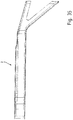
- eine andere Konfiguration des Endabschnitts eines Querträgers in einer Seitenansicht;
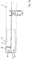
- Figur 39
- eine Stirnansicht auf das Querträgerende gemäß der Darstellung von
Figur 38 ; - Figur 40
- eine weitere Ausführungsform eines Instrumententafelträgers mit der Darstellung des fahrerseitigen Längenabschnitts eines Querträgers in einer Perspektive;
- Figur 41
- eine weitere Ausführungsform eines erfindungsgemäßen Instrumententafelträgers in einer perspektivischen Darstellung;
- Figur 42
- den fahrerseitigen Längenabschnitt des Instrumententafelträgers gemäß der Darstellung von
Figur 41 ; - Figur 43
- den Endabschnitt des Längenabschnitts gemäß der Darstellung von
Figur 42 aus einer anderen Perspektive und - Figur 44
- das Montagebauteil entsprechend der Darstellung der
Figuren 41 bis 43 in einer Perspektive. - Einander entsprechende Bauteile und Bauteilkomponenten sind in allen Figuren mit den gleichen Bezugszeichen versehen.
- Die
Figur 1 zeigt einen Instrumententafelträger in einer perspektivischen Darstellung. Der Instrumententafelträger weist einen Querträger 1 auf. Der Querträger 1 ist zwischen hier nicht dargestellten A-Säulen einer Fahrzeugkarosserie eingliederbar und erstreckt sich im Wesentlichen horizontal verlaufend quer zwischen den A-Säulen. Der Querträger 1 besteht aus einem fahrerseitigen Längenabschnitt 2 und einem beifahrerseitigen Längenabschnitt 3, die über ein Verbindungsbauteil 4 miteinander gekoppelt sind. Der beifahrerseitige Längenabschnitt 3 ist durch ein gradlinig verlaufendes Rohr gebildet. Der fahrerseitige Längenabschnitt 2 ist durch U-O-Formen eines Blechzuschnittes geformt und weist über seine Längserstreckung einen variierenden Querschnittsverlauf auf. Im Bereich der Lenksäulenanbindung 5 besitzt der fahrerseitige Längenabschnitt 2 einen annähernd kreisrund geformten Tragabschnitt 6. Am Querträger 1 sind des Weiteren Abstützstreben 7 vorgesehen. - Am A-säulenseitigen Ende 8 des beifahrerseitigen Längenabschnitts 3 ist ein Montagebauteil 9 an das Ende 8 des Querträgers 1 gefügt. Über dieses Montagebauteil 9 erfolgt die Anbindung des Querträgers 1 an der beifahrerseitigen A-Säule.
- In den
Figuren 2 bis 40 ist jeweils der fahrerseitige Längenabschnitt 2 eines Querträgers 1 oder Teile davon dargestellt und erläutert. Grundsätzlich weist ein Querträger 1 der in Rede stehenden Bauart einen beifahrerseitigen Längenabschnitt 3 auf, der so oder ähnlich wie in derFigur 1 dargestellt aufgebaut ist und mit dem fahrerseitigen Längenabschnitt 2 gekoppelt ist. - Die Anbindung des Querträgers 1 an die fahrerseitige A-Säule erfolgt über ein Montagebauteil 10, von welchem eine erste Ausführungsform anhand der
Figuren 2 bis 10 erläutert ist. - Das Montagebauteil 10 ist U-förmig konfiguriert und weist einen Steg 11 sowie zwei Schenkel 12, 13 auf.
- Das Ende 14 des fahrerseitigen Längenabschnitts 2 ist im Wesentlichen rechteckförmig konfiguriert. Das Montagebauteil 10 ist mit den Schenkeln 12, 13 am Ende 14 des Querträgers 1 gefügt. Hierbei greifen die Schenkel 12, 13 über den vertikal verlaufenden vorderen Seitenabschnitt 15 und den vertikal verlaufenden hinteren Seitenabschnitt 16 des Endes 14, so dass das Montagebauteil 10 mit den Schenkeln 12, 13 die Seitenabschnitte 15, 16 des Endes 14 partiell umgreift und mit dem Ende 14 gefügt ist.
- In jedem Schenkel 12, 13 sind übereinander und mit vertikalem Abstand a zueinander Montageöffnungen 17, 18, 19, 20 vorgesehen. Die obere Montageöffnung 17 im ersten vorderen Schenkel 12 und die obere Montageöffnung 19 im zweiten hinteren Schenkel 13 liegen auf einem Höhenniveau und auf einer Achse. Ebenso liegen die untere Montageöffnung 18 im ersten vorderen Schenkel 12 und die untere Montageöffnung 20 im zweiten hinteren Schenkel 13 auf einem Höhenniveau und auf einer Achse. Zwischen den Schenkeln 12, 13 sind Verstärkungselemente 21 eingegliedert. Diese stützen sich an den Innenseiten 22, 23 der Schenkel 12, 13 ab.
- Die Verstärkungselemente 21 sind durch U-förmige Stützkörper gebildet, die zwischen den beiden oberen Montageöffnungen 17, 19 und zwischen den beiden unteren Montageöffnungen 18, 20 des Montagebauteils 10 vorgesehen sind. Die offene Seite des U-förmigen Stützkörpers weist zum Steg 11 des Montagebauteils 10.
- Die Montageöffnungen 17 - 20 und die Verstärkungselemente 21 sind so zueinander angeordnet, dass längliche Befestigungsmittel, insbesondere Montageschrauben, durch die Montageöffnungen 17, 19 bzw. 18, 20 und die hülsen- bzw. U-förmigen Verstärkungselemente 21 in Fahrzeuglängsrichtung (x-Achse) hindurchgeführt werden können. Hierbei verläuft ein Befestigungsmittel parallel zur Längserstreckung des Verstärkungselements 21 und wird von diesem umgriffen. Über das Montagebauteil 10 und die Befestigungsmittel erfolgt die Festlegung des Querträgers 1 an der fahrerseitigen A-Säule eines Kraftfahrzeugs.
- Der fahrerseitige Längenabschnitt 2 des Querträgers 1, wie in den
Figuren 2 bis 4 oder7 bis 9 ersichtlich, ist aus zwei Schalenbauteilen 24, 25, sogenannten Halbschalen, zusammengesetzt, die entlang ihrer Stoßkanten 26, 27 zumindest partiell gefügt sind. - Der fahrerseitige Längenabschnitt 2 des Querträgers 1 gemäß den Darstellungen in den
Figuren 11 bis 13 sowie 15 bis 17 ist durch U-O-Formen eines Blechzuschnitts geformt. Aneinander kontaktierende Stoßkanten 28, 29 des Längenabschnitts 2 sind stoffschlüssig zumindest abschnittsweise miteinander gefügt. - Das Montagebauteil 10 schließt oberseitig etwa bündig mit der Oberseite 30 des fahrerseitigen Längenabschnitts 2 ab. Unterseitig steht das Montagebauteil 10 in z-Richtung gegenüber der Unterseite 31 des fahrerseitigen Längenabschnitts 2 vor.
- Die Schenkel 12, 13 ebenso wie der Steg 11 des Montagebauteils 10 sind in Abstimmung auf die Querschnittsgeometrie des Endes 14 des fahrerseitigen Längenabschnitts 2 konfiguriert. Über die Länge der Schenkel 12, 13 in Fahrzeugquerachse (y-Achse) wird die Montagelage des Querträgers 1 innerhalb des Kraftfahrzeugs bestimmt.
- Die
Figur 10 zeigt eine Ausführung eines Montagebauteils 10, bei der die Schenkel 12, 13 an ihren zum Ende 14 des fahrerseitigen Längenabschnitts 2 gerichteten freien Längskanten jeweils eine nach vorne gerichtete Umstellung 32 aufweisen. Auf diese Weise kann erreicht werden, dass sich die Schenkel 12, 13 des Montagebauteils 10 in einer Vertikalebene zu den vertikalen Wandabschnitten des Endes 14 erstrecken bzw. in der Vertikalebene verlaufen. Des Weiteren kann die Umstellung 32 eine Positionierhilfe bzw. Fügehilfe für das Montagebauteil 10 bilden. - Bei der Ausführungsform des Querträgers 1, wie anhand der
Figuren 11 bis 19 ersichtlich, ist das Montagebauteil 10 U-förmig konfiguriert mit einem Steg 11 und zwei Schenkeln 12, 13. Zwischen den Schenkeln 12, 13 erstrecken sich U-förmige Verstärkungselemente 21, welche im Bereich der zueinander in z-Achse auf dem gleichen Höhenniveau liegenden Montageöffnungen 17, 19 bzw. 18, 20 eingegliedert sind. Das Montagebauteil 10 ist mit dem Steg 11 am Ende 14 des fahrerseitigen Längenabschnitts 2 des Querträgers 1 gefügt. Die Schenkel 12, 13 sind vom Ende 14 des fahrerseitigen Längenabschnitts 2 weg nach außen in y-Achse gerichtet. - Im Steg 11 des Montagebauteils 10 gemäß der Darstellungen der
Figuren 11 bis 14 ist eine Aufnahme 33 ausgebildet, die konfigurativ auf die Querschnittskonfiguration des rechteckigen Endes 14 des fahrerseitigen Längenabschnitts 2 angepasst ist. Die Aufnahme 33 weist umlaufend ein aus dem Material des Montagebauteils 10 ausgebildeten Kragen 34 auf. Das Montagebauteil 10 ist mit der Aufnahme 33 auf das Ende 14 des fahrerseitigen Längenabschnitts 2 aufgesteckt und mit diesem stoffschlüssig gefügt. Eine solche Ausgestaltung zeigen dieFiguren 15 und16 sowie dieFigur 18 . Möglich ist es auch, dass das Ende 14 des fahrerseitigen Längenabschnitts 2 in die Aufnahme 33 gesteckt ist und diese durchgreift sowie mit dem Montagebauteil 10 gefügt ist. Dies lässt eine vorteilhafte Einstellung der Position der Bauteile, also Montagebauteil 10 und Ende 14, relativ zueinander zu. - Bei dem Montagebauteil 10 gemäß der Darstellung der
Figuren 15 bis 19 ist im Steg 11 eine rechteckig konfigurierte kragenlose Aufnahme 33 vorgesehen. Der Steg 11 geht an seinen Längskanten jeweils über einen bogenförmig konfigurierten Übergangsabschnitt 35 in den Schenkel 12 bzw. 13 über. - Möglich ist es, dass ein Kragen an einer Aufnahme 33 nach innen in Richtung der Schenkel 12, 13 umgestellt ist.
- Bei der anhand der
Figuren 20 und21 ersichtlichen Ausführungsform eines Instrumententafelträgers bzw. dessen Querträgers 1 ist am Ende 14 des fahrerseitigen Längenabschnitts 2 ein L-förmiges Montagebauteil 36 gefügt. Die Darstellung derFigur 20 dient der Illustration der L-Form des Montagebauteils 36. Das Montagebauteil 36 weist einen Steg 37 und einen Schenkel 38 auf. Mit dem Steg 37 ist das Montagebauteil 36 stirnseitig am Ende 14 des Querträgers 1 bzw. des fahrerseitigen Längenabschnitts 2 gefügt. Im Schenkel 38 sind mit vertikalem Abstand a übereinander angeordnete Montageöffnungen 39, 40 vorgesehen. - Das Montagebauteil 36, wie in der
Figur 21 ersichtlich, ist L-förmig konfiguriert mit einem Steg 37 und einem Schenkel 38. Das Montagebauteil 36 weist materialeinheitlich und einstückig ein im Montagebauteil 36 ausgebildetes Verstärkungselement 41 auf. Das Verstärkungselement 41 ist mit einem Durchgang 42 für ein Befestigungsmittel versehen. Zusätzlich kann am unteren Längenabschnitt 43 des Montagebauteils 36 ein zusätzlicher Stützkörper 44 mit einer Montageöffnung 45 vorgesehen sein. - Die
Figuren 22 bis 24 sowie 25 und 26 zeigen zwei Ausgestaltungen am A-säulenseitigen Ende 14 des fahrerseitigen Längenabschnitts 2 des Querträgers 1. Das Ende 14 ist partiell ausgeschnitten und mit einer Aussparung 46 versehen. In die nach außen offene Aussparung 46 ist ein Montagebauteil 47 eingesetzt und stoffschlüssig gefügt. Das Montagebauteil 47 weist Montageöffnungen 48 zur Durchführung von Befestigungsmitteln in Fahrzeuglängsachse auf. Die Montageöffnungen 48 im Montagebauteil 47 korrespondieren mit Montageöffnungen 49 im Ende 14. Das Montagebauteil 47 vereint die Funktionen Montage, Führung der Befestigungsmittel und Verstärkung des Endes 14. - Bei der Darstellung der
Figuren 22 bis 24 schließt das Montagebauteil 47 mit dem oberen Wandabschnitt 50 und dem unteren Wandabschnitt 51 des Endes 14 des Längenabschnitts 2 ab. Bei der Ausführungsform, wie in denFiguren 25 und26 ersichtlich, schließt das Montagebauteil 47 mit dem oberen Wandabschnitt 50 des Endes 14 des fahrerseitigen Längenabschnitts 2 im Wesentlichen bündig ab. Am unteren Wandabschnitt 51 steht das Montagebauteil 47 in vertikaler Richtung gegenüber dem Ende 14 vor. - Bei dem Querträger gemäß den Darstellungen der
Figuren 27 bis 29 ist der fahrerseitige Längenabschnitt 2 in einer Vertikalebene geteilt und aus zwei Schalenbauteilen 24, 25 gebildet. Diese stoßen in Längsrichtung mit Stoßkanten 26, 27 aneinander an und sind entlang der Stoßkanten 26, 27 zumindest partiell miteinander gefügt. Das A-säulenseitige Ende 14 des fahrerseitigen Längenabschnitts 2 ist im Querschnitt im Wesentlichen rechteckig konfiguriert. - Ein sich im Bereich der Lenksäulenanbindung 5 erstreckender Tragabschnitt 52 des fahrerseitigen Längenabschnitts 2 geht über einen Übergangsabschnitt 53 in einen rechteckig konfigurierten Endabschnitt 54 über. Im Endabschnitt 54 sind mit vertikalem Abstand übereinander Montageöffnungen 55, 56, 57, 58 für den Durchgang von Befestigungsmitteln in Fahrzeuglängsrichtung (x-Achse) vorgesehen. Zwischen den oberen Montageöffnungen 55, 57 im ersten Schenkel 59 und im zweiten Schenkel 60 des Endabschnitts 54 und den unteren Montageöffnungen 56, 58 im ersten Schenkel 59 und im zweiten Schenkel 60 sind Verstärkungselemente 61 eingegliedert. Die Verstärkungselemente 61 sind hülsen- oder U-förmig konfiguriert und stützen sich an der Innenseite der Schenkel 59, 60 des Endabschnitts 54 ab. Die Verstärkungselemente 61 sind in x-Richtung orientiert.
- Der fahrerseitige Längenabschnitt 2, wie in der
Figur 30 zu erkennen, weist einen durch U-O-Formen hergestellten Tragabschnitt 52 auf, der sich zum A-säulenseitigen Ende 14 hin verjüngt. An den Tragabschnitt 52 ist ein Endabschnitt 62 angesetzt. Dieser Endabschnitt 62 besteht aus zwei Schalenbauteilen 63, 64, die miteinander gefügt sind. - Der Endabschnitt 62 schließt sich in y-Richtung an den Tragabschnitt 52 an. Im Bereich des A-säulenseitigen freien Endes 14 des Querträgers 1 ist der Endabschnitt 62 rechteckig konfiguriert und weist Montageöffnungen 55 - 58 für den Durchgang von Befestigungsmitteln in Fahrzeuglängsrichtung (x-Achse) auf. Im Endabschnitt 62 sind U-förmig konfigurierte Verstärkungselemente 61 eingegliedert. Diese verbinden jeweils die obere Montageöffnung 55 im ersten vorderen Schenkel 59 und die obere Montageöffnung 57 im zweiten hinteren Schenkel 60 sowie die untere Montageöffnung 56 im ersten vorderen Schenkel 59 und die untere Montageöffnung 58 im zweiten hinteren Schenkel 60. Die Verstärkungselemente 61 bilden einen Durchgang und erstrecken sich in Richtung der x-Achse, die durch die Montageöffnungen 55, 57 bzw. 56, 58 führt.
- Verschiedene Querschnittskonfigurationen eines Endes 14 bzw. eines Endabschnitts 54 oder 62 des fahrerseitigen Längenabschnitts 2 zeigen die
Figuren 31 bis 34 . Der fahrerseitige Längenabschnitt kann durch U-O-Formen eines Blechzuschnitts hergestellt sein. Möglich ist, dass der Längenabschnitt durch Schalenkörper gebildet ist. Hierbei kann der fahrerseitige Längenabschnitt 2 in einer Horizontalebene oder einer Vertikalebene geteilt sein. Das A-säulenseitige Ende 14 bzw. der Endabschnitt 54 oder 62 gemäß der Darstellung derFiguren 31 und32 ist annähernd D-förmig konfiguriert mit einem Radius R1 am Übergang der Oberseite zur Vorderseite und einem demgegenüber mit größerem Radius verlaufenden Radius R2 am Übergang zwischen der vorderen Seitenwand und der Unterseite. - Das Ende 14 bzw. der Endabschnitt 54, 62, wie in der
Figur 33 ersichtlich, ist im Querschnitt etwa oval konfiguriert. - Bei dem Ende 14 bzw. dem Endabschnitt 54, 62 gemäß der Darstellung in der
Figur 34 sind im oberen Wandabschnitt und im unteren Wandabschnitt sich in Längsrichtung erstreckende Sicken 65 vorgesehen. - Bei der Darstellung des fahrerseitigen Längenabschnitts 2, wie in der
Figur 35 ersichtlich, ist der Längenabschnitt 2 aus einem U-Profil oder einem Hut-Profil konfiguriert. Nicht ersichtlich sind hier erfindungsgemäße Montagebauteile zur Anbindung des Querträgers an einer A-Säule. Insbesondere ist am fahrerseitigen Ende 2 des Querträgers 1 ein Montagebauteil vorgesehen, welches U-förmig konfiguriert ist mit einem Steg und zwei Schenkeln. In den Schenkeln sind mit vertikalem Abstand zueinander zumindest zwei Montageöffnungen vorgesehen, wobei sich zwischen den Schenkeln zumindest ein sich an den Schenkeln abstützendes Verstärkungselement eingegliedert ist. - Bei der in den
Figuren 36 und37 dargestellten Variante ist der Endabschnitt 66 des fahrerseitigen Längenabschnitts 2 bereichsweise ausgeschnitten. In die zum Ende 14 des Querträgers 1 hin offene Aussparung 67 ist ein Montagebauteil 68 eingesetzt. Im Montagebauteil 68 ebenso wie im Endabschnitt 66 sind Montageöffnungen 69 mit dazwischen eingegliederten Verstärkungselementen 70 vorgesehen. - Während die Darstellungen der
Figuren 36 und37 eine Aussparung 67 im Bereich der vorderen Seitenwand 71 des Endabschnitts 66 zeigen, ist bei der Ausführungsform gemäß der Darstellung derFiguren 38 und39 ein Bereich der Oberseite 72 und der vorderen Seitenwand 73 und der hinteren Seitenwand 74 des Endabschnitts 66 durch eine Aussparung 67 freigemacht und durch ein Montagebauteil 68 verschlossen. - Auch die
Figur 40 zeigt den fahrerseitigen Längenabschnitt 2 eines Querträgers 1, an dessen Ende 14 ein U-förmig konfiguriertes Montagebauteil 10 gefügt ist. Das Montagebauteil 10 weist einen Steg 11 und zwei Schenkel 12, 13 auf. Das Montagebauteil 10 ist mit dem Steg 11 stirnseitig vor das Ende 14 des fahrerseitigen Längenabschnitts 2 angesetzt und stoffschlüssig mit dem Ende 14 gefügt. Mit vertikalem Abstand übereinander sind in jedem Schenkel 12, 13 jeweils zwei Montageöffnungen 17 - 20 vorgesehen. Zwischen den Schenkeln 12, 13 sind hier nicht ersichtliche sich auf den Innenseiten der Schenkel 12, 13 abstützende Verstärkungselemente eingegliedert. - Die
Figur 41 zeigt eine weitere Ausführungsform eines Instrumententafelträgers und dessen Querträger 1. Der Querträger 1 weist einen fahrerseitigen Längenabschnitt 2 und einen beifahrerseitigen Längenabschnitt 3 auf. Diese sind über ein Verbindungsbauteil 4 miteinander gekoppelt. Der beifahrerseitige Längenabschnitt 3 ist im Wesentlichen durch ein gradlinig verlaufendes Rohr gebildet. Am A-säulenseitigen Ende 8 des beifahrerseitigen Längenabschnitts 3 ist ein Montagebauteil 9 an das Ende 8 des Querträgers 1 gefügt. Das Montagebauteil 9 ist L-förmig konfiguriert und weist einen Steg 37 und einen Schenkel 38 auf. Am Montagebauteil 9 ist ein Verstärkungselement 41 gefügt, welches einen Durchgang 42 für ein Befestigungsmittel aufweist. - Die
Figur 42 zeigt den fahrerseitigen Längenabschnitt 2 des Querträgers 1. - Die
Figur 43 zeigt den Endabschnitt bzw. das Ende 14 des fahrerseitigen Längenabschnitts 2. Am Ende 14 ist ein Montagebauteil 10 gefügt. Das Montagebauteil 10 ist im horizontalen Querschnitt U-förmig konfiguriert und weist einen Steg 11 und zwei Schenkel 12, 13 auf. Die Konfiguration entspricht der Ausführung des Montagebauteils 10, wie anhand derFiguren 2 bis 6 beschrieben. Auf die entsprechenden Erläuterungen wird verwiesen. - In jedem Schenkel 12, 13 sind übereinander und mit vertikalem Abstand Montageöffnungen 17, 19 bzw. 18, 20 vorgesehen. Die auf einem Höhenniveau liegenden Montageöffnungen 17, 19 bzw. 18, 20 korrespondieren zueinander und sind zur Durchführung eines länglichen Befestigungselements, insbesondere einer Montageschraube, ausgelegt. Weiterhin sind Verstärkungselemente 21 eingegliedert, welche sich zwischen den Schenkeln 12, 13 erstrecken und sich an diesen abstützen.
- Die Verstärkungselemente 21 sind vorteilhaft, jedoch nicht zwingend. Ein Montagebauteil 10 kann folglich auch ohne Verstärkungselemente ausgeführt sein.
- Das Montagebauteil 10, wie in den
Figuren 41 bis 44 dargestellt, weist an seiner Oberseite 75 einen durch eine Abkantung gebildeten Deckelschenkel 76 auf. Der Deckelschenkel 76 deckt die Oberseite 75 des Montagebauteils 10 ab und greift über das Ende 14 des fahrerseitigen Längenabschnitts 2 des Querträgers 1. - Der Deckelschenkel 76 und die vertikal in z-Achse verlaufenden Schenkel 12, 13 des Montagebauteils 10 können miteinander stoffschlüssig gefügt sein.
- Nicht dargestellt, aber optional möglich, ist, dass das Montagebauteil 10 an seiner Unterseite 77 einen Bodenschenkel aufweist. Der Bodenschenkel ist in gleicher Weise gestaltet wie der Deckelschenkel 76 an der Oberseite 75 des Montagebauteils 10.
- Das Montagebauteil 10 gemäß der Darstellung der
Figuren 41 bis 44 , ebenso wie das Montagebauteil 10, wie in denFiguren 1 bis 19 dargestellt und erläutert, ist aus einem Blechzuschnitt hergestellt, welcher der Abwicklung des Montagebauteils entspricht. Der Blechzuschnitt ist entsprechend umformtechnisch bearbeitet, so dass sich die U-förmige Konfiguration mit Steg 11 und Schenkeln 12, 13 sowie optional mit einem Deckelschenkel 76 an der Oberseite 75 und/oder einem Bodenschenkel an der Unterseite 77 ergibt. - Der fahrerseitige Längenabschnitt 2 des Querträgers 1 ist in einer horizontalen Längsebene geteilt und aus zwei Schalenbauteilen hergestellt. Möglich ist es auch, dass der fahrerseitige Längenabschnitt 2 durch U-O-Formen eines Blechzuschnitts hergestellt ist. Des Weiteren kann der fahrerseitige Längenabschnitt 2 auch durch Innenhochdruckumformung geformt sein.
-
- 1
- - Querträger
- 2
- - fahrerseitiger Längenabschnitt
- 3
- - beifahrerseitiger Längenabschnitt
- 4
- - Verbindungsbauteil
- 5
- - Lenksäulenanbindung
- 6
- - Tragabschnitt
- 7
- - Abstützstreben
- 8
- - Ende
- 9
- - Montagebauteil
- 10
- - Montagebauteil
- 11
- - Steg
- 12
- - Schenkel
- 13
- - Schenkel
- 14
- - Ende
- 15
- - vorderer Seitenabschnitt
- 16
- - hinterer Seitenabschnitt
- 17
- - Montageöffnung
- 18
- - Montageöffnung
- 19
- - Montageöffnung
- 20
- - Montageöffnung
- 21
- - Verstärkungselemente
- 22
- - Innenseite
- 23
- - Innenseite
- 24
- - Schalenbauteil
- 25
- - Schalenbauteil
- 26
- - Stoßkante
- 27
- - Stoßkante
- 28
- - Stoßkante
- 29
- - Stoßkante
- 30
- - Oberseite
- 31
- - Unterseite
- 32
- - Umstellung
- 33
- - Aufnahme
- 34
- - Kragen
- 35
- - Übergangsabschnitt
- 36
- - Montagebauteil
- 37
- - Steg
- 38
- - Schenkel
- 39
- - Montageöffnung
- 40
- - Montageöffnung
- 41
- - Verstärkungselemente
- 42
- - Durchgang
- 43
- - unterer Längenabschnitt
- 44
- - Stützkörper
- 45
- - Montageöffnung
- 46
- - Aussparung
- 47
- - Montagebauteil
- 48
- - Montageöffnung
- 49
- - Montageöffnung
- 50
- - oberer Wandabschnitt
- 51
- - unterer Wandabschnitt
- 52
- - Tragabschnitt
- 53
- - Übergangsabschnitt
- 54
- - Endabschnitt
- 55
- - Montageöffnung
- 56
- - Montageöffnung
- 57
- - Montageöffnung
- 58
- - Montageöffnung
- 59
- - Schenkel
- 60
- - Schenkel
- 61
- - Verstärkungselement
- 62
- - Endabschnitt
- 63
- - Schalenbauteil
- 64
- - Schalenbauteil
- 65
- - Sicken
- 66
- - Endabschnitt
- 67
- - Aussparung
- 68
- - Montagebauteil
- 69
- - Montageöffnungen
- 70
- - Verstärkungselement
- 71
- - Seitenwand
- 72
- - Oberseite
- 73
- - vordere Seitenwand
- 74
- - hintere Seitenwand
- 75
- - Oberseite von 10
- 76
- - Deckelschenkel
- 77
- - Unterseite von 10
- a
- - Abstand
Claims (22)
- Instrumententafelträger für ein Kraftfahrzeug, der einen zwischen den A-Säulen einer Kraftfahrzeugkarosserie eingliederbaren Querträger (1) aufweist, wobei der Querträger (1) zumindest an einem Ende (14) mit einem Montagebauteil (10) zur Befestigung an einer A-Säule versehen ist, dadurch gekennzeichnet, dass das Montagebauteil (10) U-förmig konfiguriert ist und einen Steg (11) mit zwei Schenkeln (12, 13) aufweist und in jedem Schenkel (12, 13) zumindest eine Montageöffnung (17 - 20) vorgesehen ist.
- Instrumententafelträger nach Anspruch 1, dadurch gekennzeichnet, dass zumindest zwei mit vertikalem Abstand zueinander angeordnete Montageöffnungen (17 - 20) vorgesehen sind.
- Instrumententafelträger nach Anspruch 1 oder 2, dadurch gekennzeichnet, dass zwischen die Schenkel (12, 13) zumindest ein sich an den Schenkeln (12, 13) abstützendes Verstärkungselement (21) eingegliedert ist.
- Instrumententafelträger nach einem der Ansprüche 1 bis 3, dadurch gekennzeichnet, dass das Verstärkungselement (21) zwischen einer Montageöffnung (17, 18) im ersten Schenkel (12) und einer Montageöffnung (19, 20) im zweiten Schenkel (13) angeordnet ist.
- Instrumententafelträger nach Anspruch 3 oder 4, dadurch gekennzeichnet, dass das Verstärkungselement (21) eine Hülse ist oder ein im Querschnitt U-, V-, S- oder Z-förmig konfigurierter Stützkörper ist.
- Instrumententafelträger nach einem der Ansprüche 1 bis 5, dadurch gekennzeichnet, dass das Montagebauteil (10) mit den Schenkeln (12, 13) am Ende (14) des Querträgers (1) gefügt ist.
- Instrumententafelträger nach Anspruch 6, dadurch gekennzeichnet, dass das Montagebauteil (10) mit den Schenkeln (12, 13) Seitenabschnitte (15, 16) des Endes (14) umgreift.
- Instrumententafelträger nach einem der Ansprüche 1 bis 7, dadurch gekennzeichnet, dass das Montagebauteil (10) mit dem Steg (11) am Ende (14) des Querträgers (1) gefügt ist.
- Instrumententafelträger nach einem der Ansprüche 1 bis 8, dadurch gekennzeichnet, dass ein fahrerseitiger Längenabschnitt (2) des Querträgers (1) durch U-O-Formen eines Blechzuschnitts geformt ist und in Längsrichtung des Längenabschnitts (2) einander kontaktierende Stoßkanten (28, 29) zumindest bereichsweise miteinander stoffschlüssig gefügt sind.
- Instrumententafelträger nach einem der Ansprüche 1 bis 9, dadurch gekennzeichnet, dass das Montagebauteil (10) an seiner Oberseite (75) einen Deckelschenkel (76) und/oder an seiner Unterseite einen Bodenschenkel aufweist.
- Instrumententafelträger nach einem der Ansprüche 1 bis 10, dadurch gekennzeichnet, dass ein fahrerseitiger Längenabschnitt (2) des Querträgers (1) aus zumindest zwei Schalenbauteilen (24, 25) zusammengesetzt ist.
- Instrumententafelträger nach einem der Ansprüche 1 bis 11, dadurch gekennzeichnet, dass zumindest ein Längenabschnitt (2, 3) des Querträgers (1) durch Innenhochdruckumformung geformt ist.
- Instrumententafelträger für ein Kraftfahrzeug, der einen zwischen den A-Säulen einer Kraftfahrzeugkarosserie eingliederbaren Querträger (1) aufweist, wobei der Querträger (1) zumindest an einem Ende (14) mit einem Montagebauteil (36) zur Befestigung an einer A-Säule versehen ist, dadurch gekennzeichnet, dass das Montagebauteil (36) L-förmig konfiguriert ist und einen Steg (37) und einen Schenkel (38) aufweist und ein Verstärkungselement (41) am Montagebauteil (36) gefügt ist, wobei das Verstärkungselement (41) einen Durchgang (42) für ein Befestigungsmittel aufweist.
- Instrumententafelträger für ein Kraftfahrzeug, der einen zwischen den A-Säulen einer Kraftfahrzeugkarosserie eingliederbaren Querträger (1) aufweist, dadurch gekennzeichnet, dass der fahrerseitige Längenabschnitt (2) des Querträgers (1) aus zwei Schalenbauteilen (24, 25) zusammen gesetzt ist, wobei ein A-säulenseitiger Endabschnitt (54) des fahrerseitigen Längenabschnitts (2) rechteckförmig konfiguriert ist und Montageöffnungen (55 - 58) aufweist für den Durchgang von Befestigungsmitteln in Fahrzeuglängsrichtung (x-Achse) und wobei im Endabschnitt (54) zumindest ein sich zwischen Schenkeln (59, 60) des Endabschnitts (54) abstützendes Verstärkungselement (61) eingegliedert ist.
- Instrumententafelträger für ein Kraftfahrzeug, der einen zwischen den A-Säulen einer Kraftfahrzeugkarosserie eingliederbaren Querträger (1) aufweist, dadurc h gekennzeichnet, dass der fahrerseitige Längenabschnitt (2) einen Endabschnitt (62) aufweist, welcher aus zwei Schalenbauteilen (63, 64) zusammengesetzt ist, wobei der Endabschnitt (62) rechteckförmig konfiguriert ist und Montageöffnungen (55 - 58) aufweist für den Durchgang von Befestigungsmitteln in Fahrzeuglängsrichtung (x-Achse) und wobei im Endabschnitt (62) zumindest ein sich zwischen Schenkeln (59, 60) des Endabschnitts (62) abstützendes Verstärkungselement (61) eingegliedert ist.
- Instrumententafelträger nach einem der Ansprüche 1 bis 15, dadurch gekennzeichnet, dass der fahrerseitige Längenabschnitt (2) des Querträgers (1) in einer Vertikalebene geteilt ist.
- Instrumententafelträger nach einem der Ansprüche 1 bis 15, dadurch gekennzeichnet, dass der fahrerseitige Längenabschnitt (2) des Querträgers (1) in einer Horizontalebene geteilt ist.
- Instrumententafelträger nach einem der Ansprüche 1 bis 17, dadurch gekennzeichnet, dass der A-säulenseitige Endabschnitt des fahrerseitigen Längenabschnitts (2) des Querträgers (1) rechteckförmig konfiguriert ist.
- Instrumententafelträger nach einem der Ansprüche 1 bis 17, dadurch gekennzeichnet, dass der A-säulenseitige Endabschnitt des fahrerseitigen Längenabschnitts (2) des Querträgers (1) oval ausgebildet ist.
- Instrumententafelträger nach einem der Ansprüche 1 bis 19, dadurch gekennzeichnet, dass Sicken (65) in der oberen und/oder der unteren Seitenwand des A-säulenseitige Endabschnitts des fahrerseitigen Längenabschnitts (2) des Querträgers (1) vorgesehen sind.
- Instrumententafelträger nach einem der Ansprüche 1 bis 20, dadurch gekennzeichnet, dass zumindest in einer Seitenwand des A-säulenseitige Endabschnitts des fahrerseitigen Längenabschnitts (2) des Querträgers (1) eine zum Ende (14) des Querträgers (1) hin offene Aussparung (67) vorgesehen ist.
- Instrumententafelträger nach Anspruch 21, dadurch gekennzeichnet, dass in die Aussparung (67) ein Montagebauteil (68) eingesetzt ist, welches zumindest eine Montageöffnung (69) für den Durchgang eines Befestigungsmittels in Fahrzeuglängsrichtung (x-Achse) aufweist.
Priority Applications (7)
| Application Number | Priority Date | Filing Date | Title |
|---|---|---|---|
| EP20207000.9A EP3786032B1 (de) | 2020-11-11 | 2020-11-11 | Instrumententafelträger für ein kraftfahrzeug |
| PL20207000.9T PL3786032T3 (pl) | 2020-11-11 | 2020-11-11 | Wspornik tablicy rozdzielczej dla pojazdu silnikowego |
| ES20207000T ES2934173T3 (es) | 2020-11-11 | 2020-11-11 | Soporte de cuadro de instrumentos para un vehículo de motor |
| EP22193013.4A EP4122803B1 (de) | 2020-11-11 | 2020-11-11 | Instrumententafelträger für ein kraftfahrzeug |
| ES20211942T ES2961150T3 (es) | 2020-11-11 | 2020-12-04 | Soporte de panel de instrumentos para un vehículo de motor |
| PL20211942.6T PL4001065T3 (pl) | 2020-11-11 | 2020-12-04 | Wspornik tablicy rozdzielczej do pojazdu silnikowego |
| EP20211942.6A EP4001065B1 (de) | 2020-11-11 | 2020-12-04 | Instrumententafelträger für ein kraftfahrzeug |
Applications Claiming Priority (1)
| Application Number | Priority Date | Filing Date | Title |
|---|---|---|---|
| EP20207000.9A EP3786032B1 (de) | 2020-11-11 | 2020-11-11 | Instrumententafelträger für ein kraftfahrzeug |
Related Child Applications (1)
| Application Number | Title | Priority Date | Filing Date |
|---|---|---|---|
| EP22193013.4A Division EP4122803B1 (de) | 2020-11-11 | 2020-11-11 | Instrumententafelträger für ein kraftfahrzeug |
Publications (2)
| Publication Number | Publication Date |
|---|---|
| EP3786032A1 true EP3786032A1 (de) | 2021-03-03 |
| EP3786032B1 EP3786032B1 (de) | 2022-09-21 |
Family
ID=73343959
Family Applications (3)
| Application Number | Title | Priority Date | Filing Date |
|---|---|---|---|
| EP22193013.4A Active EP4122803B1 (de) | 2020-11-11 | 2020-11-11 | Instrumententafelträger für ein kraftfahrzeug |
| EP20207000.9A Active EP3786032B1 (de) | 2020-11-11 | 2020-11-11 | Instrumententafelträger für ein kraftfahrzeug |
| EP20211942.6A Active EP4001065B1 (de) | 2020-11-11 | 2020-12-04 | Instrumententafelträger für ein kraftfahrzeug |
Family Applications Before (1)
| Application Number | Title | Priority Date | Filing Date |
|---|---|---|---|
| EP22193013.4A Active EP4122803B1 (de) | 2020-11-11 | 2020-11-11 | Instrumententafelträger für ein kraftfahrzeug |
Family Applications After (1)
| Application Number | Title | Priority Date | Filing Date |
|---|---|---|---|
| EP20211942.6A Active EP4001065B1 (de) | 2020-11-11 | 2020-12-04 | Instrumententafelträger für ein kraftfahrzeug |
Country Status (3)
| Country | Link |
|---|---|
| EP (3) | EP4122803B1 (de) |
| ES (2) | ES2934173T3 (de) |
| PL (2) | PL3786032T3 (de) |
Cited By (2)
| Publication number | Priority date | Publication date | Assignee | Title |
|---|---|---|---|---|
| CN115570977A (zh) * | 2021-06-21 | 2023-01-06 | 大众汽车股份公司 | 机动车的仪表板支架和仪表板支架装置及其制造方法 |
| CN117087766A (zh) * | 2022-05-13 | 2023-11-21 | 长城汽车股份有限公司 | 仪表板装配结构以及车辆 |
Citations (16)
| Publication number | Priority date | Publication date | Assignee | Title |
|---|---|---|---|---|
| US6176544B1 (en) * | 1997-12-19 | 2001-01-23 | Alcoa Inc. | Instrument panel reinforcement structure including a novel driver side cross tube |
| DE10121402A1 (de) | 2001-05-02 | 2002-11-07 | Volkswagen Ag | Querträger, insbesondere für eine Schalttafel eines Kraftfahrzeugs |
| US20040056463A1 (en) * | 2001-11-26 | 2004-03-25 | General Electric Company | Instrument panel thermoplastic energy absorbers |
| US6817382B2 (en) | 2001-11-08 | 2004-11-16 | Bestex Kyoel Co., Ltd. | Pile member |
| WO2005090145A1 (de) | 2004-03-17 | 2005-09-29 | Behr Gmbh & Co. Kg | Querträger oder strukturbauteil für ein kraftfahrzeug |
| EP1655208A1 (de) | 2004-11-05 | 2006-05-10 | Alcan Technology & Management Ltd. | Instrumententafelträgerstruktur |
| EP1816055A1 (de) * | 2006-02-06 | 2007-08-08 | Skoda Auto a.s. | Armaturenbretträger eines Fahrzeuges |
| DE102005004605B4 (de) | 2005-02-01 | 2009-03-05 | Lisa Dräxlmaier GmbH | Querträgermodul für ein Kraftfahrzeug |
| WO2009080968A1 (fr) | 2007-12-14 | 2009-07-02 | Faurecia Interieur Industrie | Poutre pour tableau de bord de véhicule automobile |
| FR2926526B1 (fr) | 2008-01-22 | 2010-06-04 | Faurecia Interieur Ind | Traverse de vehicule automobile, planche de bord et procede de fabrication correspondants |
| US20130154300A1 (en) * | 2011-12-20 | 2013-06-20 | Benteler Automobiltechnik Gmbh | Dashboard support, and method for the production of a dashboard support |
| DE202013011387U1 (de) * | 2012-12-27 | 2014-04-09 | Faurecia Intérieur Industrie | Fahrzeug-Traversenanordnung |
| EP2542462B1 (de) | 2010-03-05 | 2014-05-07 | Faurecia Interieur Industrie | Querträger für das armaturenbrett eines kraftfahrzeugs |
| EP2499038B1 (de) | 2009-11-13 | 2014-05-28 | Faurecia Interieur Industrie | Armaturenbrettstruktur für kraftfahrzeuge und kraftfahrzeug mit einer solchen struktur |
| US20160052395A1 (en) * | 2014-08-22 | 2016-02-25 | Benteler Automobiltechnik Gmbh | Method for producing an instrument panel support |
| DE102018126048A1 (de) * | 2018-10-19 | 2020-04-23 | Benteler Automobiltechnik Gmbh | Querträgeranordnung in einem Fahrzeug |
Family Cites Families (7)
| Publication number | Priority date | Publication date | Assignee | Title |
|---|---|---|---|---|
| FR2783490B1 (fr) * | 1998-09-21 | 2000-12-08 | Vallourec Vitry | Structure de support creuse de forme allongee comportant un bouchon anti-effondrement et bouchon anti-effondrement pour une telle structure |
| DE10221654B4 (de) * | 2001-10-01 | 2005-10-13 | Dura Automotive Plettenberg Entwicklungs- Und Vertriebs Gmbh | Querträger für ein Kraftfahrzeug |
| DE102005011331A1 (de) * | 2004-03-19 | 2005-10-13 | Behr Gmbh & Co. Kg | Querträger mit integrierter Luftführung für ein Kraftfahrzeug |
| DE102004030689A1 (de) * | 2004-06-24 | 2006-01-19 | Behr Gmbh & Co. Kg | Querträger |
| FR3024969B1 (fr) * | 2014-08-21 | 2016-08-26 | Peugeot Citroen Automobiles Sa | Ensemble comportant une traverse de planche de bord et des supports pour fixer cette traverse a la caisse d' vehicule automobile |
| DE102015101393A1 (de) * | 2015-01-30 | 2016-08-04 | Kirchhoff Automotive Deutschland Gmbh | Modulträgerbaugruppe für ein Kraftfahrzeug |
| DE102017006470B3 (de) * | 2017-07-08 | 2019-01-10 | Audi Ag | Verfahren zur Montage eines Head-up-Displays an einem Modulquerträger eines Fahrzeugs sowie Modulquerträger |
-
2020
- 2020-11-11 ES ES20207000T patent/ES2934173T3/es active Active
- 2020-11-11 PL PL20207000.9T patent/PL3786032T3/pl unknown
- 2020-11-11 EP EP22193013.4A patent/EP4122803B1/de active Active
- 2020-11-11 EP EP20207000.9A patent/EP3786032B1/de active Active
- 2020-12-04 EP EP20211942.6A patent/EP4001065B1/de active Active
- 2020-12-04 PL PL20211942.6T patent/PL4001065T3/pl unknown
- 2020-12-04 ES ES20211942T patent/ES2961150T3/es active Active
Patent Citations (16)
| Publication number | Priority date | Publication date | Assignee | Title |
|---|---|---|---|---|
| US6176544B1 (en) * | 1997-12-19 | 2001-01-23 | Alcoa Inc. | Instrument panel reinforcement structure including a novel driver side cross tube |
| DE10121402A1 (de) | 2001-05-02 | 2002-11-07 | Volkswagen Ag | Querträger, insbesondere für eine Schalttafel eines Kraftfahrzeugs |
| US6817382B2 (en) | 2001-11-08 | 2004-11-16 | Bestex Kyoel Co., Ltd. | Pile member |
| US20040056463A1 (en) * | 2001-11-26 | 2004-03-25 | General Electric Company | Instrument panel thermoplastic energy absorbers |
| WO2005090145A1 (de) | 2004-03-17 | 2005-09-29 | Behr Gmbh & Co. Kg | Querträger oder strukturbauteil für ein kraftfahrzeug |
| EP1655208A1 (de) | 2004-11-05 | 2006-05-10 | Alcan Technology & Management Ltd. | Instrumententafelträgerstruktur |
| DE102005004605B4 (de) | 2005-02-01 | 2009-03-05 | Lisa Dräxlmaier GmbH | Querträgermodul für ein Kraftfahrzeug |
| EP1816055A1 (de) * | 2006-02-06 | 2007-08-08 | Skoda Auto a.s. | Armaturenbretträger eines Fahrzeuges |
| WO2009080968A1 (fr) | 2007-12-14 | 2009-07-02 | Faurecia Interieur Industrie | Poutre pour tableau de bord de véhicule automobile |
| FR2926526B1 (fr) | 2008-01-22 | 2010-06-04 | Faurecia Interieur Ind | Traverse de vehicule automobile, planche de bord et procede de fabrication correspondants |
| EP2499038B1 (de) | 2009-11-13 | 2014-05-28 | Faurecia Interieur Industrie | Armaturenbrettstruktur für kraftfahrzeuge und kraftfahrzeug mit einer solchen struktur |
| EP2542462B1 (de) | 2010-03-05 | 2014-05-07 | Faurecia Interieur Industrie | Querträger für das armaturenbrett eines kraftfahrzeugs |
| US20130154300A1 (en) * | 2011-12-20 | 2013-06-20 | Benteler Automobiltechnik Gmbh | Dashboard support, and method for the production of a dashboard support |
| DE202013011387U1 (de) * | 2012-12-27 | 2014-04-09 | Faurecia Intérieur Industrie | Fahrzeug-Traversenanordnung |
| US20160052395A1 (en) * | 2014-08-22 | 2016-02-25 | Benteler Automobiltechnik Gmbh | Method for producing an instrument panel support |
| DE102018126048A1 (de) * | 2018-10-19 | 2020-04-23 | Benteler Automobiltechnik Gmbh | Querträgeranordnung in einem Fahrzeug |
Cited By (3)
| Publication number | Priority date | Publication date | Assignee | Title |
|---|---|---|---|---|
| CN115570977A (zh) * | 2021-06-21 | 2023-01-06 | 大众汽车股份公司 | 机动车的仪表板支架和仪表板支架装置及其制造方法 |
| CN115570977B (zh) * | 2021-06-21 | 2026-03-13 | 大众汽车股份公司 | 机动车的仪表板支架和仪表板支架装置及其制造方法 |
| CN117087766A (zh) * | 2022-05-13 | 2023-11-21 | 长城汽车股份有限公司 | 仪表板装配结构以及车辆 |
Also Published As
| Publication number | Publication date |
|---|---|
| EP4001065B1 (de) | 2023-09-20 |
| EP4122803A1 (de) | 2023-01-25 |
| EP4001065A1 (de) | 2022-05-25 |
| EP4122803B1 (de) | 2025-08-13 |
| EP3786032B1 (de) | 2022-09-21 |
| ES2961150T3 (es) | 2024-03-08 |
| PL3786032T3 (pl) | 2023-01-30 |
| PL4001065T3 (pl) | 2024-02-19 |
| ES2934173T3 (es) | 2023-02-17 |
Similar Documents
| Publication | Publication Date | Title |
|---|---|---|
| EP1228948B1 (de) | Querträger für eine Armaturentafel eines Fahrzeugs | |
| DE60208774T2 (de) | Hybrides raumfachwerk für kraftfahrzeuge | |
| DE60221416T2 (de) | Modularer unterboden für ein kraftfahrzeug | |
| DE10220025A1 (de) | Querträger | |
| DE102009026299A9 (de) | Cockpitquerträger für ein Kraftfahrzeug | |
| EP1073579A1 (de) | Karosseriestruktur eines kraftfahrzeuges | |
| EP2025424B1 (de) | Verfahren zur Herstellung eines rohrförmigen Tragprofils für einen Instrumententräger | |
| EP1880784A2 (de) | Verbund aus einem Leichtmetallgussbauteil und einem Stahlbauteil | |
| DE29916470U1 (de) | Instrumententräger | |
| DE20008201U1 (de) | Instrumententafelträger | |
| DE102010014533B4 (de) | Cockpitquerträger und Verfahren zu dessen Herstellung | |
| DE29916466U1 (de) | Instrumententräger | |
| EP3786032B1 (de) | Instrumententafelträger für ein kraftfahrzeug | |
| DE102011056699A1 (de) | Verfahren zur Herstellung eines Instrumententafelträgers sowie Instrumententafelträger | |
| DE10260529B4 (de) | Hilfsrahmen für ein Kraftfahrzeug und Herstellungsverfahren hierfür | |
| DE10359746B4 (de) | Montageträger für eine Instrumententafel | |
| EP0673829A2 (de) | Träger für die Lenksäule eines Kraftfahrzeuges | |
| DE102009026297B4 (de) | Cockpitquerträger mit variablem Lenksäulenneigungswinkel | |
| EP1977960B1 (de) | Querträger für ein Kraftfahrzeug | |
| EP0897361A1 (de) | Rahmen | |
| DE102022120872B3 (de) | Instrumententafelträger | |
| EP4108553B1 (de) | Instrumententafelträger für ein kraftfahrzeug und eine instrumententafelträgeranordnung sowie ein verfahren zu deren herstellung | |
| DE10057181A1 (de) | Instrumententräger | |
| DE102021114283A1 (de) | Baugruppe für ein Kraftfahrzeug, umfassend einen Instrumententafelträger und ein Aggregat | |
| DE102005044063A1 (de) | Karosseriesäule eines Kraftfahrzeugs, seitlicher Dachkanal und dreischenkelige Knotenverbindung |
Legal Events
| Date | Code | Title | Description |
|---|---|---|---|
| PUAI | Public reference made under article 153(3) epc to a published international application that has entered the european phase |
Free format text: ORIGINAL CODE: 0009012 |
|
| STAA | Information on the status of an ep patent application or granted ep patent |
Free format text: STATUS: THE APPLICATION HAS BEEN PUBLISHED |
|
| AK | Designated contracting states |
Kind code of ref document: A1 Designated state(s): AL AT BE BG CH CY CZ DE DK EE ES FI FR GB GR HR HU IE IS IT LI LT LU LV MC MK MT NL NO PL PT RO RS SE SI SK SM TR |
|
| AX | Request for extension of the european patent |
Extension state: BA ME |
|
| STAA | Information on the status of an ep patent application or granted ep patent |
Free format text: STATUS: REQUEST FOR EXAMINATION WAS MADE |
|
| STAA | Information on the status of an ep patent application or granted ep patent |
Free format text: STATUS: EXAMINATION IS IN PROGRESS |
|
| 17P | Request for examination filed |
Effective date: 20210831 |
|
| 17Q | First examination report despatched |
Effective date: 20210928 |
|
| GRAP | Despatch of communication of intention to grant a patent |
Free format text: ORIGINAL CODE: EPIDOSNIGR1 |
|
| STAA | Information on the status of an ep patent application or granted ep patent |
Free format text: STATUS: GRANT OF PATENT IS INTENDED |
|
| INTG | Intention to grant announced |
Effective date: 20220527 |
|
| GRAS | Grant fee paid |
Free format text: ORIGINAL CODE: EPIDOSNIGR3 |
|
| GRAA | (expected) grant |
Free format text: ORIGINAL CODE: 0009210 |
|
| STAA | Information on the status of an ep patent application or granted ep patent |
Free format text: STATUS: THE PATENT HAS BEEN GRANTED |
|
| AK | Designated contracting states |
Kind code of ref document: B1 Designated state(s): AL AT BE BG CH CY CZ DE DK EE ES FI FR GB GR HR HU IE IS IT LI LT LU LV MC MK MT NL NO PL PT RO RS SE SI SK SM TR |
|
| REG | Reference to a national code |
Ref country code: GB Ref legal event code: FG4D Free format text: NOT ENGLISH |
|
| REG | Reference to a national code |
Ref country code: CH Ref legal event code: EP |
|
| REG | Reference to a national code |
Ref country code: DE Ref legal event code: R096 Ref document number: 502020001733 Country of ref document: DE |
|
| REG | Reference to a national code |
Ref country code: IE Ref legal event code: FG4D Free format text: LANGUAGE OF EP DOCUMENT: GERMAN |
|
| REG | Reference to a national code |
Ref country code: AT Ref legal event code: REF Ref document number: 1519831 Country of ref document: AT Kind code of ref document: T Effective date: 20221015 |
|
| REG | Reference to a national code |
Ref country code: LT Ref legal event code: MG9D |
|
| REG | Reference to a national code |
Ref country code: NL Ref legal event code: MP Effective date: 20220921 |
|
| PG25 | Lapsed in a contracting state [announced via postgrant information from national office to epo] |
Ref country code: SE Free format text: LAPSE BECAUSE OF FAILURE TO SUBMIT A TRANSLATION OF THE DESCRIPTION OR TO PAY THE FEE WITHIN THE PRESCRIBED TIME-LIMIT Effective date: 20220921 Ref country code: RS Free format text: LAPSE BECAUSE OF FAILURE TO SUBMIT A TRANSLATION OF THE DESCRIPTION OR TO PAY THE FEE WITHIN THE PRESCRIBED TIME-LIMIT Effective date: 20220921 Ref country code: NO Free format text: LAPSE BECAUSE OF FAILURE TO SUBMIT A TRANSLATION OF THE DESCRIPTION OR TO PAY THE FEE WITHIN THE PRESCRIBED TIME-LIMIT Effective date: 20221221 Ref country code: LV Free format text: LAPSE BECAUSE OF FAILURE TO SUBMIT A TRANSLATION OF THE DESCRIPTION OR TO PAY THE FEE WITHIN THE PRESCRIBED TIME-LIMIT Effective date: 20220921 Ref country code: LT Free format text: LAPSE BECAUSE OF FAILURE TO SUBMIT A TRANSLATION OF THE DESCRIPTION OR TO PAY THE FEE WITHIN THE PRESCRIBED TIME-LIMIT Effective date: 20220921 Ref country code: FI Free format text: LAPSE BECAUSE OF FAILURE TO SUBMIT A TRANSLATION OF THE DESCRIPTION OR TO PAY THE FEE WITHIN THE PRESCRIBED TIME-LIMIT Effective date: 20220921 |
|
| REG | Reference to a national code |
Ref country code: ES Ref legal event code: FG2A Ref document number: 2934173 Country of ref document: ES Kind code of ref document: T3 Effective date: 20230217 |
|
| PG25 | Lapsed in a contracting state [announced via postgrant information from national office to epo] |
Ref country code: HR Free format text: LAPSE BECAUSE OF FAILURE TO SUBMIT A TRANSLATION OF THE DESCRIPTION OR TO PAY THE FEE WITHIN THE PRESCRIBED TIME-LIMIT Effective date: 20220921 Ref country code: GR Free format text: LAPSE BECAUSE OF FAILURE TO SUBMIT A TRANSLATION OF THE DESCRIPTION OR TO PAY THE FEE WITHIN THE PRESCRIBED TIME-LIMIT Effective date: 20221222 |
|
| PG25 | Lapsed in a contracting state [announced via postgrant information from national office to epo] |
Ref country code: SM Free format text: LAPSE BECAUSE OF FAILURE TO SUBMIT A TRANSLATION OF THE DESCRIPTION OR TO PAY THE FEE WITHIN THE PRESCRIBED TIME-LIMIT Effective date: 20220921 Ref country code: RO Free format text: LAPSE BECAUSE OF FAILURE TO SUBMIT A TRANSLATION OF THE DESCRIPTION OR TO PAY THE FEE WITHIN THE PRESCRIBED TIME-LIMIT Effective date: 20220921 Ref country code: PT Free format text: LAPSE BECAUSE OF FAILURE TO SUBMIT A TRANSLATION OF THE DESCRIPTION OR TO PAY THE FEE WITHIN THE PRESCRIBED TIME-LIMIT Effective date: 20230123 |
|
| PG25 | Lapsed in a contracting state [announced via postgrant information from national office to epo] |
Ref country code: SK Free format text: LAPSE BECAUSE OF FAILURE TO SUBMIT A TRANSLATION OF THE DESCRIPTION OR TO PAY THE FEE WITHIN THE PRESCRIBED TIME-LIMIT Effective date: 20220921 Ref country code: IS Free format text: LAPSE BECAUSE OF FAILURE TO SUBMIT A TRANSLATION OF THE DESCRIPTION OR TO PAY THE FEE WITHIN THE PRESCRIBED TIME-LIMIT Effective date: 20230121 Ref country code: EE Free format text: LAPSE BECAUSE OF FAILURE TO SUBMIT A TRANSLATION OF THE DESCRIPTION OR TO PAY THE FEE WITHIN THE PRESCRIBED TIME-LIMIT Effective date: 20220921 |
|
| REG | Reference to a national code |
Ref country code: DE Ref legal event code: R097 Ref document number: 502020001733 Country of ref document: DE |
|
| REG | Reference to a national code |
Ref country code: DE Ref legal event code: R081 Ref document number: 502020001733 Country of ref document: DE Owner name: VOLKSWAGEN AG, DE Free format text: FORMER OWNER: BENTELER AUTOMOBILTECHNIK GMBH, 33102 PADERBORN, DE Ref country code: DE Ref legal event code: R081 Ref document number: 502020001733 Country of ref document: DE Owner name: BENTELER AUTOMOBILTECHNIK GMBH, DE Free format text: FORMER OWNER: BENTELER AUTOMOBILTECHNIK GMBH, 33102 PADERBORN, DE |
|
| PG25 | Lapsed in a contracting state [announced via postgrant information from national office to epo] |
Ref country code: NL Free format text: LAPSE BECAUSE OF FAILURE TO SUBMIT A TRANSLATION OF THE DESCRIPTION OR TO PAY THE FEE WITHIN THE PRESCRIBED TIME-LIMIT Effective date: 20220921 Ref country code: MC Free format text: LAPSE BECAUSE OF FAILURE TO SUBMIT A TRANSLATION OF THE DESCRIPTION OR TO PAY THE FEE WITHIN THE PRESCRIBED TIME-LIMIT Effective date: 20220921 Ref country code: AL Free format text: LAPSE BECAUSE OF FAILURE TO SUBMIT A TRANSLATION OF THE DESCRIPTION OR TO PAY THE FEE WITHIN THE PRESCRIBED TIME-LIMIT Effective date: 20220921 |
|
| REG | Reference to a national code |
Ref country code: BE Ref legal event code: MM Effective date: 20221130 |
|
| PLBE | No opposition filed within time limit |
Free format text: ORIGINAL CODE: 0009261 |
|
| STAA | Information on the status of an ep patent application or granted ep patent |
Free format text: STATUS: NO OPPOSITION FILED WITHIN TIME LIMIT |
|
| PG25 | Lapsed in a contracting state [announced via postgrant information from national office to epo] |
Ref country code: DK Free format text: LAPSE BECAUSE OF FAILURE TO SUBMIT A TRANSLATION OF THE DESCRIPTION OR TO PAY THE FEE WITHIN THE PRESCRIBED TIME-LIMIT Effective date: 20220921 |
|
| 26N | No opposition filed |
Effective date: 20230622 |
|
| PG25 | Lapsed in a contracting state [announced via postgrant information from national office to epo] |
Ref country code: SI Free format text: LAPSE BECAUSE OF FAILURE TO SUBMIT A TRANSLATION OF THE DESCRIPTION OR TO PAY THE FEE WITHIN THE PRESCRIBED TIME-LIMIT Effective date: 20220921 Ref country code: LU Free format text: LAPSE BECAUSE OF NON-PAYMENT OF DUE FEES Effective date: 20221111 |
|
| PG25 | Lapsed in a contracting state [announced via postgrant information from national office to epo] |
Ref country code: IE Free format text: LAPSE BECAUSE OF NON-PAYMENT OF DUE FEES Effective date: 20221111 |
|
| PG25 | Lapsed in a contracting state [announced via postgrant information from national office to epo] |
Ref country code: BE Free format text: LAPSE BECAUSE OF NON-PAYMENT OF DUE FEES Effective date: 20221130 |
|
| PG25 | Lapsed in a contracting state [announced via postgrant information from national office to epo] |
Ref country code: CY Free format text: LAPSE BECAUSE OF FAILURE TO SUBMIT A TRANSLATION OF THE DESCRIPTION OR TO PAY THE FEE WITHIN THE PRESCRIBED TIME-LIMIT Effective date: 20220921 |
|
| PG25 | Lapsed in a contracting state [announced via postgrant information from national office to epo] |
Ref country code: MK Free format text: LAPSE BECAUSE OF FAILURE TO SUBMIT A TRANSLATION OF THE DESCRIPTION OR TO PAY THE FEE WITHIN THE PRESCRIBED TIME-LIMIT Effective date: 20220921 Ref country code: IT Free format text: LAPSE BECAUSE OF FAILURE TO SUBMIT A TRANSLATION OF THE DESCRIPTION OR TO PAY THE FEE WITHIN THE PRESCRIBED TIME-LIMIT Effective date: 20220921 |
|
| PG25 | Lapsed in a contracting state [announced via postgrant information from national office to epo] |
Ref country code: TR Free format text: LAPSE BECAUSE OF FAILURE TO SUBMIT A TRANSLATION OF THE DESCRIPTION OR TO PAY THE FEE WITHIN THE PRESCRIBED TIME-LIMIT Effective date: 20220921 |
|
| REG | Reference to a national code |
Ref country code: CH Ref legal event code: PL |
|
| PG25 | Lapsed in a contracting state [announced via postgrant information from national office to epo] |
Ref country code: CH Free format text: LAPSE BECAUSE OF NON-PAYMENT OF DUE FEES Effective date: 20231130 |
|
| PG25 | Lapsed in a contracting state [announced via postgrant information from national office to epo] |
Ref country code: HU Free format text: LAPSE BECAUSE OF FAILURE TO SUBMIT A TRANSLATION OF THE DESCRIPTION OR TO PAY THE FEE WITHIN THE PRESCRIBED TIME-LIMIT; INVALID AB INITIO Effective date: 20201111 Ref country code: CH Free format text: LAPSE BECAUSE OF NON-PAYMENT OF DUE FEES Effective date: 20231130 Ref country code: BG Free format text: LAPSE BECAUSE OF FAILURE TO SUBMIT A TRANSLATION OF THE DESCRIPTION OR TO PAY THE FEE WITHIN THE PRESCRIBED TIME-LIMIT Effective date: 20220921 |
|
| PG25 | Lapsed in a contracting state [announced via postgrant information from national office to epo] |
Ref country code: MT Free format text: LAPSE BECAUSE OF FAILURE TO SUBMIT A TRANSLATION OF THE DESCRIPTION OR TO PAY THE FEE WITHIN THE PRESCRIBED TIME-LIMIT Effective date: 20220921 |
|
| GBPC | Gb: european patent ceased through non-payment of renewal fee |
Effective date: 20241111 |
|
| PG25 | Lapsed in a contracting state [announced via postgrant information from national office to epo] |
Ref country code: GB Free format text: LAPSE BECAUSE OF NON-PAYMENT OF DUE FEES Effective date: 20241111 |
|
| PGFP | Annual fee paid to national office [announced via postgrant information from national office to epo] |
Ref country code: DE Payment date: 20251127 Year of fee payment: 6 |
|
| PGFP | Annual fee paid to national office [announced via postgrant information from national office to epo] |
Ref country code: AT Payment date: 20260113 Year of fee payment: 5 |
|
| PGFP | Annual fee paid to national office [announced via postgrant information from national office to epo] |
Ref country code: FR Payment date: 20251126 Year of fee payment: 6 |
|
| PGFP | Annual fee paid to national office [announced via postgrant information from national office to epo] |
Ref country code: CZ Payment date: 20251104 Year of fee payment: 6 |
|
| PGFP | Annual fee paid to national office [announced via postgrant information from national office to epo] |
Ref country code: PL Payment date: 20251031 Year of fee payment: 6 |
|
| PGFP | Annual fee paid to national office [announced via postgrant information from national office to epo] |
Ref country code: ES Payment date: 20251229 Year of fee payment: 6 |