EP3785686B1 - Entbindungsbett - Google Patents
Entbindungsbett Download PDFInfo
- Publication number
- EP3785686B1 EP3785686B1 EP20193694.5A EP20193694A EP3785686B1 EP 3785686 B1 EP3785686 B1 EP 3785686B1 EP 20193694 A EP20193694 A EP 20193694A EP 3785686 B1 EP3785686 B1 EP 3785686B1
- Authority
- EP
- European Patent Office
- Prior art keywords
- support part
- frame
- out frame
- foot support
- slide
- Prior art date
- Legal status (The legal status is an assumption and is not a legal conclusion. Google has not performed a legal analysis and makes no representation as to the accuracy of the status listed.)
- Active
Links
Images


Classifications
-
- A—HUMAN NECESSITIES
- A61—MEDICAL OR VETERINARY SCIENCE; HYGIENE
- A61G—TRANSPORT, PERSONAL CONVEYANCES, OR ACCOMMODATION SPECIALLY ADAPTED FOR PATIENTS OR DISABLED PERSONS; OPERATING TABLES OR CHAIRS; CHAIRS FOR DENTISTRY; FUNERAL DEVICES
- A61G13/00—Operating tables; Auxiliary appliances therefor
- A61G13/0009—Obstetrical tables or delivery beds
-
- A—HUMAN NECESSITIES
- A61—MEDICAL OR VETERINARY SCIENCE; HYGIENE
- A61G—TRANSPORT, PERSONAL CONVEYANCES, OR ACCOMMODATION SPECIALLY ADAPTED FOR PATIENTS OR DISABLED PERSONS; OPERATING TABLES OR CHAIRS; CHAIRS FOR DENTISTRY; FUNERAL DEVICES
- A61G13/00—Operating tables; Auxiliary appliances therefor
- A61G13/02—Adjustable operating tables; Controls therefor
-
- A—HUMAN NECESSITIES
- A61—MEDICAL OR VETERINARY SCIENCE; HYGIENE
- A61G—TRANSPORT, PERSONAL CONVEYANCES, OR ACCOMMODATION SPECIALLY ADAPTED FOR PATIENTS OR DISABLED PERSONS; OPERATING TABLES OR CHAIRS; CHAIRS FOR DENTISTRY; FUNERAL DEVICES
- A61G13/00—Operating tables; Auxiliary appliances therefor
- A61G13/10—Parts, details or accessories
- A61G13/12—Rests specially adapted therefor; Arrangements of patient-supporting surfaces
- A61G13/1205—Rests specially adapted therefor; Arrangements of patient-supporting surfaces for specific parts of the body
- A61G13/1245—Knees, upper or lower legs
-
- A—HUMAN NECESSITIES
- A61—MEDICAL OR VETERINARY SCIENCE; HYGIENE
- A61G—TRANSPORT, PERSONAL CONVEYANCES, OR ACCOMMODATION SPECIALLY ADAPTED FOR PATIENTS OR DISABLED PERSONS; OPERATING TABLES OR CHAIRS; CHAIRS FOR DENTISTRY; FUNERAL DEVICES
- A61G13/00—Operating tables; Auxiliary appliances therefor
- A61G13/10—Parts, details or accessories
- A61G13/12—Rests specially adapted therefor; Arrangements of patient-supporting surfaces
- A61G13/1205—Rests specially adapted therefor; Arrangements of patient-supporting surfaces for specific parts of the body
- A61G13/125—Ankles or feet
Definitions
- the invention relates to a bed, particularly a delivery bed, comprising a support frame, a back support part mounted on the support frame for the purpose of supporting the back of a user, and a foot support part for supporting the feet of the user.
- Beds in general and patient care beds in particular can be adjusted to all sorts of positions. It is thus often possible to place a backrest partially upright via an adjusting mechanism in order to provide improved comfort for a patient.
- a backrest partially upright via an adjusting mechanism in order to provide improved comfort for a patient.
- delivery beds it is often not only the backrest that is adjustable, but the footrest can also be folded away and the legs of the patient can be placed on two stirrups.
- Beds known from the prior art such as from US 6 408 464 B1 , comprise a foot support part which provides comfort when a user adopts a reclining position. In the delivery position this foot support part is absent, whereby the patient need not switch beds when childbirth is taking place. In the prior art this is solved by providing a foot support part which can be removed as a whole.
- the foot support part is preferably removed as late as possible before the delivery.
- the moment of delivery can however not always be accurately predicted, and removing the foot support part requires multiple operations and therefore takes a relatively long time.
- Removal must further take place with great certainty, and must not fail. Finally, removal must take place while the patient is already on the bed. As a precaution, the delivery bed is therefore sometimes converted well before the delivery, which results in a waiting time and thereby in less comfort for the patient.
- WO 93/09750 A1 and CN 101 773 439 B show further known beds.
- An object of the present invention is to provide a bed wherein the above stated drawback is at least partially obviated.
- a further object is to provide a bed, particularly a delivery bed, which can be adjusted with a high degree of certainty, speed and reliability between different positions, for instance a reclining position in which the user can lie on the bed and be supported fully, and a delivery position in which the user can rest in the desired birthing position.
- At least one of the objectives is achieved at least partially in a bed, particularly a delivery bed according to claim 1.
- the foot support part is stored in the storage space under the back support part when it is not needed, such as during childbirth.
- the storage space can here be provided in the support frame itself or can be provided somewhere else. Because the foot support part and back support part extend mutually in line (and, in the case that the foot support part and back support part are disposed horizontally, because both support parts extend at the same height), the bed enables a completely flat upper side of the bed and thereby a comfortable reclining position of the user. When the foot support part is temporarily not needed, for instance during childbirth, it can be pushed away into a storage space.
- the storage space is embodied and positioned such that the medical personnel caring for the user need not be inconvenienced thereby at all.
- the displacing unit is not only configured to hold the foot support part substantially horizontal in the fully slid-in and fully slid-out position, the foot support part also extends substantially horizontally during the sliding in and out.
- the fact that the foot support part then does not protrude upward makes the sliding in and out more convenient when a user has taken up position on the bed.
- the fact that the foot support part then does not protrude downward means that the bed can be disposed close to the ground without the foot support part touching the ground, which would restrict sliding in.
- the displacing unit comprises:
- the coupling mechanism can comprise pivot arms.
- the pivot arms are arranged pivotally on the lower and upper slide-out frame.
- the slide-out frames and the pivot arms preferably form a parallelogram construction. In the latter case it is not just the case that the one slide-out frame follows the other slide-out frame when the one slide-out frame is slid in or out in longitudinal direction, but the slide-out frames can also be displaced toward each other or away from each other in a direction transversely of the longitudinal direction, this such that the two slide-out frames remain positioned parallel to each other.
- the displacing unit is configured to displace the foot support part from the wholly slid-in position in substantially horizontal direction first, and then also displace the foot support part in vertical direction. Guiding the upper slide-out frame in this way has the advantage that the upper slide-out frame is not displaced in the vertical direction unexpectedly, which could result in a blocking of the foot support part when the foot support part is situated in the vicinity of other elements of the bed.
- the displacing unit comprises:
- the division of this movement has the advantage that it is possible to displace the foot support part out of the support frame in (substantially) its entirety first, before it is slid upward.
- a space between the foot support part and the support frame hereby remains constant during sliding out, and a mattress or pillow can remain in place during the sliding in and out of the foot support part.
- the displacing means comprise:
- the displacing unit comprises a drive for driving the displacement of the lower slide-out frame.
- This drive comprises a scissor construction, connected on a first side to a head end of the support frame and connected on a second, opposite side to the lower slide-out frame, and an actuator, arranged at the head of the bed and configured to lengthen or shorten the scissor construction in order to move the lower slide-out frame respectively out of and into the storage space in horizontal direction relative to the support frame.
- This construction has the advantage that the space in the support frame which is taken up by the displacing means is located substantially at the head end, whereby there is a lot of space for the foot support part at the foot end.
- the actuator can here be embodied as one single extending cylinder, particularly a hydraulic or pneumatic extending cylinder. This makes the drive simple and reliable. It is preferred for the actuator to be a hydraulic or pneumatic actuator. This enables the foot support part to be slid in or slid out electrically and thereby remotely controlled, and still at a reasonable speed. Such actuators also ensure that the foot support part can be displaced almost silently.
- the lower slide-out frame is displaced substantially horizontally by rails during the horizontal and vertical displacement of the foot support part.
- the rails are arranged on either side of the lower slide-out frame, and/or the plate is arranged parallel to the rails, on either side of the upper slide-out frame. This enables the two frames to rest on enough support points, and no undesired leverage is created when a user leans on an outermost side of the foot support part, which could cause a great amount of force on the opposite side.
- the upper slide-out frame moves through the substantially horizontal slot part during the horizontal displacement of the foot support part so that this frame is displaced substantially horizontally.
- the upper slide-out frame further moves through a substantially inclining slot part during the vertical displacement of the foot support part, and the upper slide-out frame is thereby displaced in accordance with the path described by the inclining slot part.
- the displacing unit further comprises one or more extension elements for lifting the upper slide-out frame and the foot support part mounted or formed thereon to a height position above the maximum height of the outer end of the slot, wherein the extension elements are preferably arranged at opposite positions on a transverse rod of the guide.
- the bed also comprises a pelvis support part for supporting the pelvis of the user.
- pivoting means are provided for the purpose of pivoting at least one of the back support part, pelvis support part and foot support part independently of each other.
- the bed has a pelvis support part which is arranged at the foot end of the backrest and is adjustable using a further actuator between a first position, in which the pelvis support part is disposed substantially horizontally, and a second position in which the pelvis support part is disposed obliquely toward the head end. A user can sit on such a pelvis support when it has been adjusted, without this pelvis support getting in the way when the bed is set up as a lying surface.
- the back support part can otherwise also be embodied for adjustment, for instance using an actuator, between a first position, in which the backrest is disposed substantially horizontally, and a second position, in which the backrest is disposed obliquely toward the foot end.
- the displacing unit comprises one or more actuators which are electrically powered by a battery which is arranged on the bed, particularly the support frame.
- Electrical adjusting means have the advantage that they require less power from a user or practitioner, particularly when they are powered via a battery, since the bed is hereby less dependent on its environment and can hereby be employed in different environments.
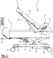
- Figure 1 shows a delivery bed 1 comprising a mobile frame 8 with wheels 9 whereby the bed 1 can travel over a ground surface, a support frame 5 disposed substantially horizontally (so parallel to the ground surface), and lifting means 11 arranged between mobile frame 8 and support frame 5.
- these lifting means 11 comprise a number of bars 11 which are arranged in a pivoting scissor construction and are mounted rotatably on mobile frame 8 and support frame 5.
- One or more of the bars can be displaced using an actuator 12.
- the shown embodiment shows an (optional) second actuator 18. The operation of the latter actuator will be elucidated below.
- Actuator 12, 18 is preferably a hydraulic or pneumatic actuator. Such actuators have the advantage, among others, that support frame 5 can be adjusted slowly and carefully.
- actuator 12, 18 comprises for instance one or more extending cylinders (as shown in figure 1 ), extending of the cylinders enables support frame 5 to be displaced in upward direction while, when the extending cylinders are retracted, support frame 5 is displaced in downward direction.
- Support frame 5 remains in a substantially horizontal position during the upward and downward displacement, whereby the patient remains reclined/seated in place on the bed and is thus inconvenienced as little as possible by the displacement.
- Actuator 12, 18 can be controlled by means of a control unit 14.
- the control unit is connected to actuator 12, 18 via a wireless or wired connection.
- Both the actuator 12, 18 and the control unit 14 can be powered by a battery 13 disposed on frame 8. When a battery is used, it remains possible to adjust for instance the height of support frame 5 when delivery bed 1 is displaced. It is also possible for actuator 12, 18 and control unit 14 to be powered by a wired connection to a socket outlet.
- delivery bed 1 comprises three sections which can be moved substantially independently of each other and which support on support frame 5, i.e. a back section 2, a foot section 4 and a pelvis section 3 positioned therebetween.
- Back section 2 comprises a back support part 20 with a first mattress part 21 placed thereon
- the pelvis part comprises a pelvis support part 30 with a second mattress part 31 placed thereon
- foot section 4 comprises a foot support part 40 with a third mattress part 41 placed thereon.
- the three sections can in principle be moved, more particularly pivoted, independently of each other relative to support frame 5 in order to be able to optimally support the patient in different positions.
- Driving of the pivoting movement of back support part 20 and pelvis support part 30 is realized by actuators 16 and 17, which can be actuators similar to actuator 12 or actuator 18. Actuators 16 and 17 can also be controlled by control unit 14.
- Figures 1-5 all show the same embodiment of delivery bed 1.
- Figure 5 shows delivery bed 1 in the so-called reclining position. In this position the back support part 20, the pelvis support part 30 and the foot support part 40 are all positioned mutually in line. In the reclining position the back support part 20, pelvis support part 30 and foot support part 40 usually extend substantially horizontally. Back support part 20, pelvis support part 30 and foot support part 40 then together form a flat whole on which the patient can lie and rest before or after the delivery.
- the sections are placed in the delivery position.
- This position is for instance shown in figures 2 and 4 .
- the back support part 20 is pivoted upward, usually to an oblique position between a horizontal and vertical position.
- Pelvis support part 30 is further also pivoted upward to an oblique position, so that the pelvis of a patient lying obliquely against back support part 20 is supported by pelvis support part 30.
- the lower legs of the patient are held up by two separate supports (not shown) provided on the sides of support frame 5.
- foot support part 40 is slid in (and thereby disappears wholly or partially under the pelvis support part and the back support part) so that foot support part 40 does not get in the way during the delivery and medical staff can optimally support the delivery.
- foot support part 40 In order to move foot support part 40 from the inclining position to the delivery position the foot support part 40 must not only be displaced in horizontal direction, but must also be displaced downward far enough that it can be placed in a storage space 43 provided under back support part 20 and pelvis support part 30. Likewise, when foot support part 40 is slid out of storage space 43 and moved to the reclining position, foot support part 40 must also be displaced upward so that foot support part 40 can be placed in line with back support part 20 and pelvis support part 30.
- a further actuator 18 can also be utilized in addition to actuator 12 during adjustment of support frame 5 relative to frame 8.
- delivery bed 1 is embodied as shown in the figures with two actuators 12, 18, it is also possible to tilt support frame 5 over the width of the bed, whereby the surface created by the two support parts 20 and 30 is adjusted relative to a surface on which delivery bed 1 is arranged.
- Rear back support part 20 can hereby for instance be moved further upward, whereby pelvis support part 30 can be moved relatively further downward. It is hereby also possible to still provide a horizontal lying surface on an uneven floor surface.
- foot support part 40 can be slid in and out will be described in more detail below.
- Foot support part 40 is displaceable relative to support frame 5 by a displacing unit.
- the displacing unit can here be configured to displace foot support part 40 both in longitudinal direction (more particularly in horizontal direction when support parts 20, 30, 40 extend horizontally) and in up and downward direction.
- the displacing unit can for instance comprise a special guide and drive mechanism.
- the guide and drive mechanism of the displacing unit comprises a lower slide-out frame 6 which is supported in support frame 5 and is displaceable therein in horizontal direction, an upper slide-out frame 7 which carries on the upper side the above stated foot support part 40, a coupling mechanism 37 provided between the lower and upper slide-out frame 6, 7 for the purpose of supporting the upper slide-out part 7, a drive for driving the displacement of the lower slide-out frame 6, and guide means for guiding upper slide-out frame 7 during the displacement of lower slide-out frame 6.
- the coupling mechanism 37 is embodied as a so-called parallelogram construction.
- a number of pivot arms, together with two parallel elongate construction parts which are mutually coupled by the pivot arms, define substantially a parallelogram form. This makes it possible to move the two coupled construction parts reciprocally in a direction perpendicularly of the longitudinal direction, wherein the construction parts are always held substantially parallel relative to each other by the pivot arms.
- Such a parallelogram construction can be formed by the elongate lower slide-out frame 6, the elongate upper slide-out frame 7 and the pivotable arms mounted therebetween.
- the lower and upper slide-out frame 6, 7 more particularly form two opposite sides of the parallelogram construction 37.
- the other opposite sides of parallelogram construction 37 are formed by the pivotable (hingable) arms 20A-20D. More particularly, a rear arm 20A and a front arm 20B is provided on a first long side of each of the lower and upper slide-out frame 6, 7, while a rear arm 20C and front arm 20D is provided on a second, opposite long side of each of the lower and upper slide-out frame 6, 7.
- the two rear arms 20A and 20C are also mutually coupled roughly halfway along via at least a first transverse arm 38, while the two front arms 20B and 20D are mutually coupled via at least a second transverse arm 39.
- each of the arms 20A-20D is further provided with hinges 24 so that they are hingeable relative to the lower and upper slide-out frame 6, 7.
- the parallelogram construction 37 is here embodied such that the upper slide-out frame 7 can be displaced between a lower position and an upper position in supported manner without the orientation of the foot support part 40 changing. In other words, foot support part 40 can be lifted and lowered while remaining in the horizontal position.
- Support frame 5 comprises an essentially flat horizontal upper plate 28.
- Two rails 25 are arranged on either side of upper plate 28.
- Each of the frame parts 6A and 6B on the long sides of lower slide-out frame 6 are further provided with wheels 33 which are placed at some distance relative to each other and which can be confined in rails 25, and whereby the lower slide-out frame 6 can be rolled reciprocally in longitudinal direction of the bed, i.e. in a substantially horizontal direction.
- Slide-out frame 6 is always supported by rails 25 on both sides in any position, i.e. in the fully slid-in position, in the fully slid-out position and in all intermediate positions.
- the drive means comprise a scissor construction 26 disposed in substantially the same plane as lower slide-out frame 6, and an actuator 27.
- Scissor construction 26 comprises a number of hingable swivel arms 29A-29D displaceable relative to each other via hinges 34, relative to a stationary transverse fixing beam 35 of support frame 5 and relative to a movable fixing beam 36 as part of the lower slide-out frame 6.
- At one free outer end swivel arm 29A is further connected hingedly via a hinge 50 to a carriage 51 which can be moved reciprocally in transverse direction 53 transversely of the longitudinal direction of bed 1 along a carriage rail 52 mounted fixedly on the upper plate.
- At one free outer end swivel arm 29D is likewise mounted hingedly via a hinge 60 on a carriage 61 which can be moved reciprocally in transverse direction 53 transversely of the longitudinal direction of bed 1 along a carriage rail 62 mounted fixedly on the upper plate.
- the drive means further comprise one or more actuators 27.
- one actuator 27 in the form of a hydraulic, pneumatic or electric extending cylinder is applied.
- This actuator 27 is connected hingedly via hinges 54 and 55 to one of the swivel arms. When extending cylinder 27 is pushed out, this has the result that a force is exerted evenly via the two hinges 34 and 60 over the width of movable fixing beam 36 and thereby of lower slide-out frame 6.
- the lower slide-out frame 6 is pulled smoothly to the slid-in position by hinge construction 26 in similar manner.
- the above stated parallelogram construction 37 between the lower and upper slide-out frame 6, 7 is provided, as is a guide construction which urges the upper slide-out frame 7 upward.
- the guide construction comprises two upright plates or side plates 65, 66 extending on either side of scissor construction 26.
- Each of the upright plates 65, 66 is provided with an elongate slot 67.
- the elongate slot has a straight slot portion 67A and a curved slot portion 67B.
- the curved slot portion 67B extends in an upward direction, as seen from the head of the bed, so as to displace the upper slide-out frame 7 upward when actuator 27 extends, as will be elucidated below.
- Guide 68 comprises essentially a transverse rod 69 extending transversely of the longitudinal direction of bed 1 and extension elements 70 provided on transverse rod 69. Extension elements 70 are arranged on transverse rod 69 at opposite positions, close to the upright plates 65, 66. Each extension element 70 is more particularly mounted with its first outer end fixedly on transverse rod 69 and arranged with its other, opposite outer end via a hinge 71 hingedly on the upper slide-out frame 7.
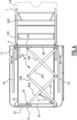
- Figures 5 and 6 show the situation in which the upper slide-out frame 7 is in the wholly slid-out position.
- the length of scissor construction 26 becomes shorter and it pulls the movable fixing beam 36 rearward in horizontal direction (in the direction of the head of the bed).
- the lower slide-out frame 6 formed thereon co-displaces. Due to the oblique position of the arms 20A, 20B of the parallelogram construction, these arms 20A, 20B also tend to pull the upper slide-out frame 7 rearward. Because the upper slide-out frame 7 is however guided in the two slots 67, the parallelogram construction collapses and slide-out frame 7 (also) moves in downward direction.
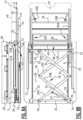
- Figures 7A and 7B show a first intermediate position in which slide-out frame 7 has already been partially pulled in (has been displaced in rearward direction and has also been displaced downward).
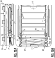
- Figures 8A and 8B and figures 9A and 9B show respective further intermediate positions in which the upper slide-out frame 7 has been displaced further in each case.
- the upper slide-out frame 7 has already been slid into storage space 43 to some extent.
- figures 10A and 10B show the delivery position in which the upper slide-out frame 7 (with the foot support part 40 and mattress 41 mounted thereon) has been pulled in fully and is located wholly in storage space 43.
- Figure 11 shows the different positions of an outer end 72 of transverse rod 69 when the lower slide-out frame 6 and the upper slid-out frame 7 coupled thereto are slid out from the fully slid-in position (for instance in the delivery position).
- P1 shows the first position, in which the transverse rod 69 (or at least outer end 72 thereof), which is connected to the upper slide-out frame 7, is situated in each of the supports 25 at the beginning of the slot 67 (i.e. the beginning of the horizontal part 67A of slot 67).
- arms 20A-20D of the parallelogram construction push upper slide-out frame 7 along and the two slide-frames 6, 7 move outward together.
- each of the outer ends 72 arrives at the curved part 67B of slot 67.
- the outer end of slide-out frame 7 connected to transverse rod 69 hereby starts moving upward.
- the parallelogram construction now ensures that the whole slide-out frame 7 moves upward, this such that the position of the upper slide-out frame 7 always remains parallel to the position of the lower slide-out frame 6. This can be seen in the parts of the figure showing the positioning at positions P3 and P4.
- the upper slide-out frame 7 is otherwise directly connected to transverse rod 69. This means that the maximum height that the upper slide-out frame 7 can reach is determined by the height at which curved part 67B of slots 67 ends.
- the upper slide-out frame 7 is however connected indirectly to transverse rod 69 of guide 68. The connection runs via the above stated extension elements 70. These make it possible to slide the upper slide-out frame 7 upward just slightly further than the highest position of slots 67 during sliding out. This makes it possible on one side to transport upper slide-out element 7 upward to an extent such that the foot support part 40 arranged thereon comes to lie exactly in line with pelvis support part 30 and/or back support part 20.
Landscapes
- Health & Medical Sciences (AREA)
- Engineering & Computer Science (AREA)
- Biomedical Technology (AREA)
- Life Sciences & Earth Sciences (AREA)
- Animal Behavior & Ethology (AREA)
- General Health & Medical Sciences (AREA)
- Public Health (AREA)
- Veterinary Medicine (AREA)
- Gynecology & Obstetrics (AREA)
- Invalid Beds And Related Equipment (AREA)
Claims (13)
- Bett, insbesondere ein Entbindungsbett (1), aufweisend:- einen Stützrahmen (5);- ein am Stützrahmen (5) angebrachtes Rückenstützteil (20) zum Stützen des Rückens eines Benutzers;- ein Fußstützteil (40) zum Stützen der Füße des Benutzers;- einen Stauraum (43) unter dem Rückenstützteil (20), geeignet, um darin das Fußstützteil (40) aufzunehmen;- eine Verschiebeeinheit zum Verschieben des Fußstützteils (40) in den bzw. aus dem Stauraum (43) zwischen einer eingeschobenen Position, in der das Fußstützteil (40) im Wesentlichen in dem Stauraum (43) aufgenommen ist, und einer herausgeschobenen Position, in der das Fußstützteil (40) zumindest teilweise aus dem Stauraum (43) herausgeschoben ist, und auf eine solche Höhe verschoben worden ist, dass sich das Fußstützteil (40) auf gleichem Niveau mit dem Rückenstützteil (20) befindet,wobei die Verschiebeeinheit aufweist:- einen unteren Ausziehrahmen (6), der verschiebbar im Stauraum (43) angeordnet ist;- einen oberen Ausziehrahmen (7), der mit dem verschiebbaren unteren Ausziehrahmen (6) über einen Kopplungsmechanismus gekoppelt ist, wobei das Fußstützteil (40) an dem oberen Ausziehrahmen (7) angeordnet oder mit diesem einstückig ausgebildet ist,wobei die Verschiebeeinheit für das Verschieben des unteren Ausziehrahmens (6) einen Antrieb aufweist, dadurch gekennzeichnet, dass der Antrieb aufweist:eine Scherenkonstruktion (26), die an einer ersten Seite mit einem Kopfende des Stützrahmens (5) und an einer zweiten, gegenüberliegenden Seite mit dem unteren Ausziehrahmen (6) verbunden ist; undeinen Aktuator (27), der am Kopfende des Bettes angeordnet ist und so ausgebildet ist, dass er die Scherenkonstruktion (26) verlängert oder verkürzt, um den unteren Ausziehrahmen (6) relativ zum Tragrahmen (5) in horizontaler Richtung in den Stauraum (43) hinein bzw. aus diesem heraus zu bewegen.
- Bett nach Anspruch 1, wobei die Verschiebeeinheit ferner aufweist:- eine erste Verschiebeeinrichtung zum Verschieben des unteren Ausziehrahmens in horizontaler Richtung, wobei die Verschiebeeinrichtung vorzugsweise eine oder mehrere Schienen umfasst, in denen der untere Ausziehrahmen hin- und herfahren kann;- eine zweite Verschiebeeinrichtung zum Verschieben des oberen Ausziehrahmens in Aufwärts- oder Abwärtsrichtung, wenn der untere Ausziehrahmen verschoben wird, wobei die zweite Verschiebeeinrichtung zwei aufrechte, neben dem unteren Ausziehrahmen beiderseits angeordnete Platten (25) aufweist, wobei jede Platte mit einem länglichen Schlitz (67) versehen ist, wobei der Schlitz einen sich im Wesentlichen horizontal erstreckenden Schlitzabschnitt (67A) und einen sich nach oben erstreckenden gebogenen Schlitzabschnitt (67B) aufweist, sowie eine mit dem oberen Ausziehrahmen (7) verbundene Führung (68) deren äußere Enden (72) in den Schlitzen (67) angeordnet und darin führbar sind.
- Bett nach einem der vorherigen Ansprüche, wobei die Verschiebeeinheit so ausgebildet ist, dass sie das Fußstützteil (40) in der vollständig eingeschobenen und vollständig herausgeschobenen Position im Wesentlichen horizontal hält, und wobei sich das Fußstützteil (40) vorzugsweise auch während des Hinein- und Herausschiebens im Wesentlichen horizontal erstreckt.
- Bett nach einem der vorherigen Ansprüche, wobei der Kopplungsmechanismus Schwenkarme (20A-20D) aufweist, welche am unteren und oberen Ausziehrahmen schwenkbar angeordnet sind, und wobei die Ausziehrahmen und die Schwenkarme eine Parallelogrammkonstruktion bilden.
- Bett nach einem der vorherigen Ansprüche, wobei der Stauraum (43) im Stützrahmen (5) vorgesehen ist.
- Bett nach einem der vorherigen Ansprüche, wobei die Verschiebeeinheit so ausgebildet ist, dass sie das Fußstützteil (40) aus der vollständig eingeschobenen Position zunächst in im Wesentlichen horizontaler Richtung verschiebt und das Fußstützteil (40) dann auch in vertikaler Richtung verschiebt.
- Bett nach einem der vorherigen Ansprüche, wobei der Aktuator (27) einen einzigen ausfahrbaren Zylinder, insbesondere einen hydraulischen oder pneumatischen ausfahrbaren Zylinder, aufweist.
- Bett nach einem der Ansprüche 2 bis 7, wobei der untere Ausziehrahmen (6) während der horizontalen und vertikalen Verschiebung des Fußstützteiles (40) durch Schienen (25) im Wesentlichen horizontal verschoben wird und/oder wobei der obere Ausziehrahmen (7) während der horizontalen Verschiebung des Fußstützteiles (40) durch den im Wesentlichen horizontalen Schlitzabschnitt (67A) bewegt und dadurch im Wesentlichen horizontal verschoben wird.
- Bett nach einem der Ansprüche 2 bis 8, wobei sich der obere Ausziehrahmen (7) während der vertikalen Verschiebung des Fußstützteils (40) durch einen im Wesentlichen geneigten Schlitzabschnitt (67B) bewegt und dabei entsprechend dem durch den geneigten Schlitzabschnitt (67A) vorgegebenen Weg verschoben wird.
- Bett nach einem der Ansprüche 2 bis 9, wobei die Verschiebeeinheit ferner ein oder mehrere Verlängerungselemente (70) aufweist, zum Anheben des oberen Ausziehrahmens (7) und des daran befestigten oder angeformten Fußstützteils (40) in eine Vertikalposition oberhalb der maximalen Höhe des äußeren Endes des Schlitzes (67), wobei die Verlängerungselemente (70) an einer Querstange (69) der Führung vorzugsweise an gegenüberliegenden Positionen angeordnet sind.
- Bett nach einem der vorherigen Ansprüche, ferner aufweisend ein Beckenstützteil (30), zum Abstützen des Beckens des Benutzers, und/oder eine Schwenkeinrichtung zum unabhängigen Verschwenken von Rückenstützteil (20) und/oder Beckenstützteil (30) und/oder Fußstützteil (40), wobei das Rückenstützteil (20) zwischen einer ersten Position, in der das Rückenstützteil (2) im Wesentlichen horizontal angeordnet ist, und einer zweiten Position, in der das Rückenstützteil schräg zum Fußende angeordnet ist, vorzugsweise, beispielsweise mittels eines Aktuators (16), verstellt werden kann.
- Bett nach einem der vorherigen Ansprüche, wobei die Verschiebeeinheit einen oder mehrere Aktuatoren umfasst, welche von einer am Bett, insbesondere am Stützrahmen (5), angeordneten Batterie (13) elektrisch versorgt werden.
- Bett nach einem der vorherigen Ansprüche, ferner aufweisend einen Rahmen (8) mit auf einer Bodenfläche anzuordnenden und zumindest teilweise unter dem Stützrahmen (5) angeordneten Rädern (9), wobei der gegenseitige Abstand zwischen dem Rahmen (8) und dem Stützrahmen (5), vorzugsweise durch einen hydraulischen oder pneumatischen Aktuator, einstellbar ist.
Applications Claiming Priority (1)
| Application Number | Priority Date | Filing Date | Title |
|---|---|---|---|
| NL2023741A NL2023741B1 (nl) | 2019-08-30 | 2019-08-30 | Bevallingsbed |
Publications (3)
| Publication Number | Publication Date |
|---|---|
| EP3785686A1 EP3785686A1 (de) | 2021-03-03 |
| EP3785686C0 EP3785686C0 (de) | 2023-11-15 |
| EP3785686B1 true EP3785686B1 (de) | 2023-11-15 |
Family
ID=68501988
Family Applications (1)
| Application Number | Title | Priority Date | Filing Date |
|---|---|---|---|
| EP20193694.5A Active EP3785686B1 (de) | 2019-08-30 | 2020-08-31 | Entbindungsbett |
Country Status (3)
| Country | Link |
|---|---|
| EP (1) | EP3785686B1 (de) |
| NL (1) | NL2023741B1 (de) |
| PL (1) | PL3785686T3 (de) |
Families Citing this family (2)
| Publication number | Priority date | Publication date | Assignee | Title |
|---|---|---|---|---|
| CN114099203B (zh) * | 2021-11-10 | 2024-04-05 | 丰都县妇幼保健院 | 一种产科用孕妇分娩床 |
| CN114246755A (zh) * | 2022-01-19 | 2022-03-29 | 朱书龙 | 一种产科用辅助多功能助产床 |
Family Cites Families (3)
| Publication number | Priority date | Publication date | Assignee | Title |
|---|---|---|---|---|
| DE59204014D1 (de) * | 1991-11-12 | 1995-11-16 | Iris Podgorschek | Gebärbett. |
| US6408464B1 (en) | 1999-08-23 | 2002-06-25 | Hill-Rom Services, Inc. | Birthing bed foot section attachment mechanism |
| CN101773439B (zh) * | 2010-02-02 | 2015-04-01 | 湖州市南浔鑫江医疗器械设备有限公司 | 一种多功能电动分娩床 |
-
2019
- 2019-08-30 NL NL2023741A patent/NL2023741B1/nl active
-
2020
- 2020-08-31 PL PL20193694.5T patent/PL3785686T3/pl unknown
- 2020-08-31 EP EP20193694.5A patent/EP3785686B1/de active Active
Also Published As
| Publication number | Publication date |
|---|---|
| EP3785686C0 (de) | 2023-11-15 |
| NL2023741B1 (nl) | 2021-04-13 |
| EP3785686A1 (de) | 2021-03-03 |
| PL3785686T3 (pl) | 2024-02-12 |
Similar Documents
| Publication | Publication Date | Title |
|---|---|---|
| US11559448B2 (en) | Medical support apparatus | |
| US7886380B2 (en) | Hospital bed | |
| US7458119B2 (en) | Bed having a chair egress position | |
| US4894876A (en) | Multipurpose maternity care bed | |
| EP1621170B1 (de) | Patientenliege mit Längenverstellvorrichtung, System und Verfahren | |
| CN102014840B (zh) | 一种担架和病人运送系统 | |
| US6826793B2 (en) | Articulating bed frame | |
| EP3785686B1 (de) | Entbindungsbett | |
| CN110101515B (zh) | 一种能够摆渡病人上下床的轮椅装置 | |
| EP2462911A2 (de) | Zur Trennung der Stuhlausfahrposition bewegliche Seitenschiene | |
| CN113017329B (zh) | 座椅家具和用于座椅家具的配件 | |
| WO2002026186A1 (en) | Power legrest for a wheelchair | |
| CN112512378B (zh) | 用于使家具结构线性、平稳地移动的单个电动双向致动器系统 | |
| JP2005124796A (ja) | ヘッドレスト装置及びそれを備えた医療用椅子並びに医療用ベッド | |
| CN210383290U (zh) | 一种多位调节美容椅 | |
| JP2014217690A (ja) | 電動フルリクライニングチェア | |
| CN210383359U (zh) | 一种美容床多位可调结构 | |
| EP3651711B1 (de) | Pflegebett | |
| EP3833314B1 (de) | Bett mit einem betätigbaren matratze-stützplattform und verfahren zum betätigen eines solchen betts | |
| CN212489175U (zh) | 一种可调节躺椅 | |
| CN108294515A (zh) | 一种双动力驱动的座椅 | |
| CN222172508U (zh) | 一种可变形的轮椅床 | |
| GB2506666A (en) | A footrest deployable from a hidden position | |
| CN210383344U (zh) | 一种两向升降美容床 | |
| US11304531B1 (en) | Raising mechanism for sitting assembly |
Legal Events
| Date | Code | Title | Description |
|---|---|---|---|
| PUAI | Public reference made under article 153(3) epc to a published international application that has entered the european phase |
Free format text: ORIGINAL CODE: 0009012 |
|
| STAA | Information on the status of an ep patent application or granted ep patent |
Free format text: STATUS: THE APPLICATION HAS BEEN PUBLISHED |
|
| AK | Designated contracting states |
Kind code of ref document: A1 Designated state(s): AL AT BE BG CH CY CZ DE DK EE ES FI FR GB GR HR HU IE IS IT LI LT LU LV MC MK MT NL NO PL PT RO RS SE SI SK SM TR |
|
| AX | Request for extension of the european patent |
Extension state: BA ME |
|
| STAA | Information on the status of an ep patent application or granted ep patent |
Free format text: STATUS: REQUEST FOR EXAMINATION WAS MADE |
|
| 17P | Request for examination filed |
Effective date: 20210903 |
|
| RBV | Designated contracting states (corrected) |
Designated state(s): AL AT BE BG CH CY CZ DE DK EE ES FI FR GB GR HR HU IE IS IT LI LT LU LV MC MK MT NL NO PL PT RO RS SE SI SK SM TR |
|
| GRAP | Despatch of communication of intention to grant a patent |
Free format text: ORIGINAL CODE: EPIDOSNIGR1 |
|
| STAA | Information on the status of an ep patent application or granted ep patent |
Free format text: STATUS: GRANT OF PATENT IS INTENDED |
|
| INTG | Intention to grant announced |
Effective date: 20230403 |
|
| GRAJ | Information related to disapproval of communication of intention to grant by the applicant or resumption of examination proceedings by the epo deleted |
Free format text: ORIGINAL CODE: EPIDOSDIGR1 |
|
| STAA | Information on the status of an ep patent application or granted ep patent |
Free format text: STATUS: REQUEST FOR EXAMINATION WAS MADE |
|
| INTC | Intention to grant announced (deleted) | ||
| GRAP | Despatch of communication of intention to grant a patent |
Free format text: ORIGINAL CODE: EPIDOSNIGR1 |
|
| STAA | Information on the status of an ep patent application or granted ep patent |
Free format text: STATUS: GRANT OF PATENT IS INTENDED |
|
| INTG | Intention to grant announced |
Effective date: 20230831 |
|
| GRAS | Grant fee paid |
Free format text: ORIGINAL CODE: EPIDOSNIGR3 |
|
| GRAA | (expected) grant |
Free format text: ORIGINAL CODE: 0009210 |
|
| STAA | Information on the status of an ep patent application or granted ep patent |
Free format text: STATUS: THE PATENT HAS BEEN GRANTED |
|
| AK | Designated contracting states |
Kind code of ref document: B1 Designated state(s): AL AT BE BG CH CY CZ DE DK EE ES FI FR GB GR HR HU IE IS IT LI LT LU LV MC MK MT NL NO PL PT RO RS SE SI SK SM TR |
|
| REG | Reference to a national code |
Ref country code: CH Ref legal event code: EP Ref country code: GB Ref legal event code: FG4D |
|
| REG | Reference to a national code |
Ref country code: DE Ref legal event code: R096 Ref document number: 602020020991 Country of ref document: DE |
|
| REG | Reference to a national code |
Ref country code: IE Ref legal event code: FG4D |
|
| U01 | Request for unitary effect filed |
Effective date: 20231117 |
|
| U07 | Unitary effect registered |
Designated state(s): AT BE BG DE DK EE FI FR IT LT LU LV MT NL PT SE SI Effective date: 20231123 |
|
| REG | Reference to a national code |
Ref country code: SK Ref legal event code: T3 Ref document number: E 43079 Country of ref document: SK |
|
| PG25 | Lapsed in a contracting state [announced via postgrant information from national office to epo] |
Ref country code: GR Free format text: LAPSE BECAUSE OF FAILURE TO SUBMIT A TRANSLATION OF THE DESCRIPTION OR TO PAY THE FEE WITHIN THE PRESCRIBED TIME-LIMIT Effective date: 20240216 |
|
| PG25 | Lapsed in a contracting state [announced via postgrant information from national office to epo] |
Ref country code: IS Free format text: LAPSE BECAUSE OF FAILURE TO SUBMIT A TRANSLATION OF THE DESCRIPTION OR TO PAY THE FEE WITHIN THE PRESCRIBED TIME-LIMIT Effective date: 20240315 |
|
| PG25 | Lapsed in a contracting state [announced via postgrant information from national office to epo] |
Ref country code: ES Free format text: LAPSE BECAUSE OF FAILURE TO SUBMIT A TRANSLATION OF THE DESCRIPTION OR TO PAY THE FEE WITHIN THE PRESCRIBED TIME-LIMIT Effective date: 20231115 |
|
| PG25 | Lapsed in a contracting state [announced via postgrant information from national office to epo] |
Ref country code: IS Free format text: LAPSE BECAUSE OF FAILURE TO SUBMIT A TRANSLATION OF THE DESCRIPTION OR TO PAY THE FEE WITHIN THE PRESCRIBED TIME-LIMIT Effective date: 20240315 Ref country code: GR Free format text: LAPSE BECAUSE OF FAILURE TO SUBMIT A TRANSLATION OF THE DESCRIPTION OR TO PAY THE FEE WITHIN THE PRESCRIBED TIME-LIMIT Effective date: 20240216 Ref country code: ES Free format text: LAPSE BECAUSE OF FAILURE TO SUBMIT A TRANSLATION OF THE DESCRIPTION OR TO PAY THE FEE WITHIN THE PRESCRIBED TIME-LIMIT Effective date: 20231115 |
|
| PG25 | Lapsed in a contracting state [announced via postgrant information from national office to epo] |
Ref country code: RS Free format text: LAPSE BECAUSE OF FAILURE TO SUBMIT A TRANSLATION OF THE DESCRIPTION OR TO PAY THE FEE WITHIN THE PRESCRIBED TIME-LIMIT Effective date: 20231115 Ref country code: NO Free format text: LAPSE BECAUSE OF FAILURE TO SUBMIT A TRANSLATION OF THE DESCRIPTION OR TO PAY THE FEE WITHIN THE PRESCRIBED TIME-LIMIT Effective date: 20240215 Ref country code: HR Free format text: LAPSE BECAUSE OF FAILURE TO SUBMIT A TRANSLATION OF THE DESCRIPTION OR TO PAY THE FEE WITHIN THE PRESCRIBED TIME-LIMIT Effective date: 20231115 |
|
| PG25 | Lapsed in a contracting state [announced via postgrant information from national office to epo] |
Ref country code: SM Free format text: LAPSE BECAUSE OF FAILURE TO SUBMIT A TRANSLATION OF THE DESCRIPTION OR TO PAY THE FEE WITHIN THE PRESCRIBED TIME-LIMIT Effective date: 20231115 Ref country code: RO Free format text: LAPSE BECAUSE OF FAILURE TO SUBMIT A TRANSLATION OF THE DESCRIPTION OR TO PAY THE FEE WITHIN THE PRESCRIBED TIME-LIMIT Effective date: 20231115 |
|
| REG | Reference to a national code |
Ref country code: DE Ref legal event code: R097 Ref document number: 602020020991 Country of ref document: DE |
|
| PLBE | No opposition filed within time limit |
Free format text: ORIGINAL CODE: 0009261 |
|
| STAA | Information on the status of an ep patent application or granted ep patent |
Free format text: STATUS: NO OPPOSITION FILED WITHIN TIME LIMIT |
|
| U20 | Renewal fee for the european patent with unitary effect paid |
Year of fee payment: 5 Effective date: 20240827 |
|
| 26N | No opposition filed |
Effective date: 20240819 |
|
| GBPC | Gb: european patent ceased through non-payment of renewal fee |
Effective date: 20240831 |
|
| PG25 | Lapsed in a contracting state [announced via postgrant information from national office to epo] |
Ref country code: MC Free format text: LAPSE BECAUSE OF FAILURE TO SUBMIT A TRANSLATION OF THE DESCRIPTION OR TO PAY THE FEE WITHIN THE PRESCRIBED TIME-LIMIT Effective date: 20231115 |
|
| PG25 | Lapsed in a contracting state [announced via postgrant information from national office to epo] |
Ref country code: GB Free format text: LAPSE BECAUSE OF NON-PAYMENT OF DUE FEES Effective date: 20240831 |
|
| PG25 | Lapsed in a contracting state [announced via postgrant information from national office to epo] |
Ref country code: IE Free format text: LAPSE BECAUSE OF NON-PAYMENT OF DUE FEES Effective date: 20240831 |
|
| U20 | Renewal fee for the european patent with unitary effect paid |
Year of fee payment: 6 Effective date: 20250827 |
|
| PGFP | Annual fee paid to national office [announced via postgrant information from national office to epo] |
Ref country code: PL Payment date: 20250801 Year of fee payment: 6 |
|
| PGFP | Annual fee paid to national office [announced via postgrant information from national office to epo] |
Ref country code: CH Payment date: 20250901 Year of fee payment: 6 |
|
| PGFP | Annual fee paid to national office [announced via postgrant information from national office to epo] |
Ref country code: CZ Payment date: 20250807 Year of fee payment: 6 |
|
| PGFP | Annual fee paid to national office [announced via postgrant information from national office to epo] |
Ref country code: SK Payment date: 20250731 Year of fee payment: 6 |
|
| PG25 | Lapsed in a contracting state [announced via postgrant information from national office to epo] |
Ref country code: CY Free format text: LAPSE BECAUSE OF FAILURE TO SUBMIT A TRANSLATION OF THE DESCRIPTION OR TO PAY THE FEE WITHIN THE PRESCRIBED TIME-LIMIT; INVALID AB INITIO Effective date: 20200831 |