EP3785670A1 - A low profile transseptal catheter and implant system for minimally invasive valve procedure - Google Patents
A low profile transseptal catheter and implant system for minimally invasive valve procedure Download PDFInfo
- Publication number
- EP3785670A1 EP3785670A1 EP20195875.8A EP20195875A EP3785670A1 EP 3785670 A1 EP3785670 A1 EP 3785670A1 EP 20195875 A EP20195875 A EP 20195875A EP 3785670 A1 EP3785670 A1 EP 3785670A1
- Authority
- EP
- European Patent Office
- Prior art keywords
- leaflet
- fastener
- catheter
- braces
- valve
- Prior art date
- Legal status (The legal status is an assumption and is not a legal conclusion. Google has not performed a legal analysis and makes no representation as to the accuracy of the status listed.)
- Granted
Links
Images



















Classifications
-
- A—HUMAN NECESSITIES
- A61—MEDICAL OR VETERINARY SCIENCE; HYGIENE
- A61F—FILTERS IMPLANTABLE INTO BLOOD VESSELS; PROSTHESES; DEVICES PROVIDING PATENCY TO, OR PREVENTING COLLAPSING OF, TUBULAR STRUCTURES OF THE BODY, e.g. STENTS; ORTHOPAEDIC, NURSING OR CONTRACEPTIVE DEVICES; FOMENTATION; TREATMENT OR PROTECTION OF EYES OR EARS; BANDAGES, DRESSINGS OR ABSORBENT PADS; FIRST-AID KITS
- A61F2/00—Filters implantable into blood vessels; Prostheses, i.e. artificial substitutes or replacements for parts of the body; Appliances for connecting them with the body; Devices providing patency to, or preventing collapsing of, tubular structures of the body, e.g. stents
- A61F2/02—Prostheses implantable into the body
- A61F2/24—Heart valves ; Vascular valves, e.g. venous valves; Heart implants, e.g. passive devices for improving the function of the native valve or the heart muscle; Transmyocardial revascularisation [TMR] devices; Valves implantable in the body
- A61F2/2427—Devices for manipulating or deploying heart valves during implantation
-
- A—HUMAN NECESSITIES
- A61—MEDICAL OR VETERINARY SCIENCE; HYGIENE
- A61F—FILTERS IMPLANTABLE INTO BLOOD VESSELS; PROSTHESES; DEVICES PROVIDING PATENCY TO, OR PREVENTING COLLAPSING OF, TUBULAR STRUCTURES OF THE BODY, e.g. STENTS; ORTHOPAEDIC, NURSING OR CONTRACEPTIVE DEVICES; FOMENTATION; TREATMENT OR PROTECTION OF EYES OR EARS; BANDAGES, DRESSINGS OR ABSORBENT PADS; FIRST-AID KITS
- A61F2/00—Filters implantable into blood vessels; Prostheses, i.e. artificial substitutes or replacements for parts of the body; Appliances for connecting them with the body; Devices providing patency to, or preventing collapsing of, tubular structures of the body, e.g. stents
- A61F2/02—Prostheses implantable into the body
- A61F2/24—Heart valves ; Vascular valves, e.g. venous valves; Heart implants, e.g. passive devices for improving the function of the native valve or the heart muscle; Transmyocardial revascularisation [TMR] devices; Valves implantable in the body
- A61F2/2409—Support rings therefor, e.g. for connecting valves to tissue
-
- A—HUMAN NECESSITIES
- A61—MEDICAL OR VETERINARY SCIENCE; HYGIENE
- A61F—FILTERS IMPLANTABLE INTO BLOOD VESSELS; PROSTHESES; DEVICES PROVIDING PATENCY TO, OR PREVENTING COLLAPSING OF, TUBULAR STRUCTURES OF THE BODY, e.g. STENTS; ORTHOPAEDIC, NURSING OR CONTRACEPTIVE DEVICES; FOMENTATION; TREATMENT OR PROTECTION OF EYES OR EARS; BANDAGES, DRESSINGS OR ABSORBENT PADS; FIRST-AID KITS
- A61F2/00—Filters implantable into blood vessels; Prostheses, i.e. artificial substitutes or replacements for parts of the body; Appliances for connecting them with the body; Devices providing patency to, or preventing collapsing of, tubular structures of the body, e.g. stents
- A61F2/02—Prostheses implantable into the body
- A61F2/24—Heart valves ; Vascular valves, e.g. venous valves; Heart implants, e.g. passive devices for improving the function of the native valve or the heart muscle; Transmyocardial revascularisation [TMR] devices; Valves implantable in the body
- A61F2/2412—Heart valves ; Vascular valves, e.g. venous valves; Heart implants, e.g. passive devices for improving the function of the native valve or the heart muscle; Transmyocardial revascularisation [TMR] devices; Valves implantable in the body with soft flexible valve members, e.g. tissue valves shaped like natural valves
-
- A—HUMAN NECESSITIES
- A61—MEDICAL OR VETERINARY SCIENCE; HYGIENE
- A61F—FILTERS IMPLANTABLE INTO BLOOD VESSELS; PROSTHESES; DEVICES PROVIDING PATENCY TO, OR PREVENTING COLLAPSING OF, TUBULAR STRUCTURES OF THE BODY, e.g. STENTS; ORTHOPAEDIC, NURSING OR CONTRACEPTIVE DEVICES; FOMENTATION; TREATMENT OR PROTECTION OF EYES OR EARS; BANDAGES, DRESSINGS OR ABSORBENT PADS; FIRST-AID KITS
- A61F2/00—Filters implantable into blood vessels; Prostheses, i.e. artificial substitutes or replacements for parts of the body; Appliances for connecting them with the body; Devices providing patency to, or preventing collapsing of, tubular structures of the body, e.g. stents
- A61F2/02—Prostheses implantable into the body
- A61F2/24—Heart valves ; Vascular valves, e.g. venous valves; Heart implants, e.g. passive devices for improving the function of the native valve or the heart muscle; Transmyocardial revascularisation [TMR] devices; Valves implantable in the body
- A61F2/2412—Heart valves ; Vascular valves, e.g. venous valves; Heart implants, e.g. passive devices for improving the function of the native valve or the heart muscle; Transmyocardial revascularisation [TMR] devices; Valves implantable in the body with soft flexible valve members, e.g. tissue valves shaped like natural valves
- A61F2/2418—Scaffolds therefor, e.g. support stents
-
- A—HUMAN NECESSITIES
- A61—MEDICAL OR VETERINARY SCIENCE; HYGIENE
- A61F—FILTERS IMPLANTABLE INTO BLOOD VESSELS; PROSTHESES; DEVICES PROVIDING PATENCY TO, OR PREVENTING COLLAPSING OF, TUBULAR STRUCTURES OF THE BODY, e.g. STENTS; ORTHOPAEDIC, NURSING OR CONTRACEPTIVE DEVICES; FOMENTATION; TREATMENT OR PROTECTION OF EYES OR EARS; BANDAGES, DRESSINGS OR ABSORBENT PADS; FIRST-AID KITS
- A61F2/00—Filters implantable into blood vessels; Prostheses, i.e. artificial substitutes or replacements for parts of the body; Appliances for connecting them with the body; Devices providing patency to, or preventing collapsing of, tubular structures of the body, e.g. stents
- A61F2/02—Prostheses implantable into the body
- A61F2/24—Heart valves ; Vascular valves, e.g. venous valves; Heart implants, e.g. passive devices for improving the function of the native valve or the heart muscle; Transmyocardial revascularisation [TMR] devices; Valves implantable in the body
- A61F2/2442—Annuloplasty rings or inserts for correcting the valve shape; Implants for improving the function of a native heart valve
- A61F2/2463—Implants forming part of the valve leaflets
-
- A—HUMAN NECESSITIES
- A61—MEDICAL OR VETERINARY SCIENCE; HYGIENE
- A61F—FILTERS IMPLANTABLE INTO BLOOD VESSELS; PROSTHESES; DEVICES PROVIDING PATENCY TO, OR PREVENTING COLLAPSING OF, TUBULAR STRUCTURES OF THE BODY, e.g. STENTS; ORTHOPAEDIC, NURSING OR CONTRACEPTIVE DEVICES; FOMENTATION; TREATMENT OR PROTECTION OF EYES OR EARS; BANDAGES, DRESSINGS OR ABSORBENT PADS; FIRST-AID KITS
- A61F2/00—Filters implantable into blood vessels; Prostheses, i.e. artificial substitutes or replacements for parts of the body; Appliances for connecting them with the body; Devices providing patency to, or preventing collapsing of, tubular structures of the body, e.g. stents
- A61F2/02—Prostheses implantable into the body
- A61F2/24—Heart valves ; Vascular valves, e.g. venous valves; Heart implants, e.g. passive devices for improving the function of the native valve or the heart muscle; Transmyocardial revascularisation [TMR] devices; Valves implantable in the body
- A61F2/2442—Annuloplasty rings or inserts for correcting the valve shape; Implants for improving the function of a native heart valve
- A61F2/2466—Delivery devices therefor
-
- A—HUMAN NECESSITIES
- A61—MEDICAL OR VETERINARY SCIENCE; HYGIENE
- A61B—DIAGNOSIS; SURGERY; IDENTIFICATION
- A61B17/00—Surgical instruments, devices or methods
- A61B17/064—Surgical staples, i.e. penetrating the tissue
Definitions
- the present application is related to the field of interventional cardiology systems and procedures and, in particular, systems and procedures for heart valve repair.
- Valve insufficiency is characterized by a loose or elastic valve structure. This often results in regurgitation wherein the valve leaflets fail to close property (“coapt”) and guard against backflow of blood.
- Valves or annuloplasty rings may be delivered to the site of the valve by catheter and expanded once properly positioned.
- a physician may have difficulty precisely positioning prosthetic devices between the mitral valve leaflets - especially when the mitral valve is insufficient.
- the prosthetic devices may slip upon expansion within the relatively elastic annulus of the insufficient mitral valve.
- a physician may provide support for the annular ring of the valve during implantation to compensate for mitral valve insufficiency. But, positioning of such support devices in a safe and minimally invasive manner is technically challenging. For example, the chordae tendinae attached to the mitral valve leaflets can interfere with efforts to support the valve or its annulus.
- mitral valve can be accessed by femoral catheterization with a fluoroscopically guided, low-profile catheter. Once the right atrium is accessed and the interatrial septum is punctured, the mitral valve can be approached from the left atrium. This approach avoids contact with the left ventricular outflow tract and the chordae tendineae.
- two leaflet braces circumnavigate the anterior and posterior mitral valve leaflets, forming a loop around each leaflet. Tension in the atrial direction from the catheter keeps the loops tightly wedged under the leaflets for the remainder of the procedure.
- a fastener joins the ends of each loop to form one annular ring circling the valve under the anterior and posterior leaflets.
- the procedure can be performed with a sub-commissural catheter to assist in steering behind the leaflets.
- a transcatheter heart valve system can then be deployed between the native leaflets. Expansion of the heart valve traps and sandwiches the native mitral valve leaflets between the valve frame and the leaflet braces.
- the procedure can be performed in catheterization laboratories and by practitioners with varying levels of expertise.
- a method of supporting a heart valve includes looping around a first leaflet of the heart valve. And, applying tension directed through the valve to the first leaflet. The method also includes performing a procedure on the heart valve.
- the method can further comprise looping around a second leaflet of the heart valve and applying tension directed through the valve to the second leaflet.
- the method can also include extending a guide catheter through the valve and advancing a first guide wire through the guide catheter.
- looping around the leaflet includes extending the first guide wire around the first leaflet.
- a second guide wire could be deployed through the guide catheter and looped around the second leaflet.
- the guide wires can include snare loops and the method includes snaring the snare loop of the guide wires after extending them around the leaflets.
- the method can also include forming first and second leaflet braces.
- a first leaflet brace extends over the first guide wire and around the first leaflet.
- a second leaflet brace is extended over the second guide wire and around the second leaflet.
- the method can also include securing adjacent ends of the leaflet braces to each other to form a closed loop, such as a circle.
- the physician can attach a first pair of adjacent ends using a first leaflet brace and a second pair of adjacent ends using a second leaflet brace.
- a replacement heart valve can be expanded within the native heart valve. Expansion for example can include releasing a self-expanding heart valve within the (native) heart valve and against the leaflets (directly) and the leaflet braces (indirectly).
- the method can also include removing excess tubing from the leaflet braces.
- all of these procedures can occur while the method applies tension to the leaflets for improved results.
- the tension on the leaflets helps with accurate positioning (and slip avoidance) during expansion of the replacement heart valve.
- the heart valve can be, for example, a mitral heart valve and the method can be used to avoid and preserve the chordae tendinae.
- Other heart valves might be aortic, tricuspid or pulmonic, or prior replacement heart valves in need of repair.
- a system for supporting a heart valve having at least two leaflets.
- the system can include at least one fastening catheter and at least one leaflet brace.
- the fastening catheter has a distal end and defines at least two adjacent lumens extending through the distal end.
- the fastening catheter also includes at least one fastener coupled to the fastening catheter, such as at the distal end.
- the leaflet brace has an elongate flexible structure configured to extend through one of the lumens of the fastening catheter and around at least one leaflet of the heart valve.
- the elongate flexible structure can include an abutment surface configured to stop advancement of the fastener over the leaflet brace.
- the elongate flexible structure can also include an inner elastic layer and an outer functional layer.
- the outer functional layer can be, for example, an ingrowth layer, a radiopaque or a shrink layer.
- the elongate flexible structure can also include a shortening mechanism, such as a tear notch defined within the elongate flexible structure.
- the system may include a first and second leaflet braces and first and second fastening catheters.
- a first pair of adjacent ends of the first and second leaflet braces are configured to extend through adjacent lumens of the first fastening catheter.
- a second pair of adjacent ends of the first and second leaflet braces are configured to extend through adjacent lumens of the second fastening catheter.
- the fastener of the first fastening catheter is configured to attach together the first pair of adjacent ends.
- the fastener of the second fastening catheter is configured to attach together the second pair of adjacent ends, thus forming an annular ring encircling the at least one leaflet of the heart valve.
- the fastener can define a pair of adjacent openings configured to align over the two adjacent lumens at the distal end and receive therethrough at least a portion of the leaflet brace.
- the fastener can also include a plurality of locking tabs extending around the adjacent openings.
- the system can also include a fastener hoop having coupled thereto the fastener of the first fastening catheter and the fastener of the second fastening catheter.
- the fastener hoop can be circular with the fasteners coupled on the opposite sides of the hoop.
- the system can also include a transseptal introducer sheath configured to deliver the at least one fastening catheter.
- the system can also include one or more barbs coupled to the at least one leaflet brace to help secure the brace to heart tissue.
- the system can also include a prosthetic valve configured to expand within the leaflets of the heart valve and the least one leaflet brace.
- the expanded prosthetic valve can sandwich the leaflets between the prosthetic valve and the at least one leaflet brace.
- the system can include an elongate coupling member (such as a suture) releasably coupling the fastener to the at least one fastening catheter.
- an elongate coupling member such as a suture
- Apparatuses and methods for performing minimally invasive mitral valve procedures are disclosed herein.
- these apparatuses and methods can be applied to full mitral valve replacement, or to mitral valve annuloplasty.
- these apparatuses and methods can also be applied to other valves.
- the procedures can be performed in catheterization laboratories and by practitioners with varying levels of expertise.
- THV trans-catheter heart valve
- the systems and methods may be employed with the balloon-expandable THV described in U.S. Patent Application Publication No. 8,764,820 , which is hereby expressly incorporated herein by reference. It should be understood, however, that the systems and methods should not be limited to use with balloon-expandable THVs. Instead, embodiments of the disclosed systems and methods can be used to secure a wide variety of THVs delivered through a variety of mechanisms (e.g., self-expanding heart valves, mechanically-expanding heart valves, other balloon-expanding heart valves, and the like). For instance, any of the embodiments described in U.S. Pat. No. 6,730,118 can be used with embodiments of the disclosed system. U.S. Pat. No. 6,730,118 is hereby expressly incorporated herein by reference.
- Access to the mitral valve can be obtained using femoral catheterization with a fluoroscopically guided, low-profile catheter.
- the right atrium is accessed and the interatrial septum punctured to get to the left atrium.
- the mitral valve is approached through the left atrium.
- this approach avoids contact with the left ventricular outflow tract and the chordae tendineae.
- Two leaflet braces are extended over guide wires to form semicircular loops that circumnavigate the anterior and posterior mitral valve leaflets. Tension is applied to the catheter from the atrial direction to keep the leaflet braces tightly wedged under the leaflets for the remainder of the procedure.
- a fastener joins the ends of each loop to create one annular ring encircling the valve under the anterior and posterior leaflets.
- the procedure can be performed with a sub-commissural catheter to assist in steering behind the leaflets.
- the remaining catheters can be separated from the leaflet braces after implantation, leaving the annular ring in place behind the leaflets.
- the annular ring formed can serve as part of an annuloplasty device.
- a transcatheter heart valve system can then be deployed between the native leaflets. Expansion of the heart valve traps and sandwiches the native mitral valve leaflets between the valve frame and the leaflet braces.
- a physician punctures the septum with a needle and advances a guide wire through the needle.
- the physician retrieves the needle, leaving a guide wire across the septum.
- the physician advances a dilator with a cone shaped distal end over the guide wire and across the septum.
- the physician then advances a transseptal introducer sheath 2 over the dilator, through the interatrial septum 4 and toward the anterior and posterior leaflets 6, 7 of a mitral valve as seen in FIG. 1A .
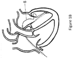
- a first double bend guide catheter 8 extends from the introducer sheath 2 to cannulate the mitral valve at the posteromedial commissure.
- the physician advances a first guide wire with a ringed end through guide catheter 8 and around the posterior leaflet 7 towards the anterolateral commissure.
- a first snare catheter 10 then cannulates the mitral valve at the anterolateral commissure.
- a first snare guide wire positioned at the distal end of the snare catheter 10 captures the first ringed guide wire and pulls it out, so that the guide wire circumvents the posterior leaflet 7 at the base of the mitral valve, as in FIG. 1C . This forms a posterior leaflet wire loop 12.
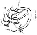
- FIGS. 1D and 1E The process is repeated in FIGS. 1D and 1E around the anterior leaflet 6 using a second double bend guide catheter 13, a second ringed guide wire (not shown), a second snare catheter 15, and a second snare guide wire (not shown). This forms an anterior leaflet wire loop 17.
- the physician retracts the guide and snare catheters, leaving the wire loops in place.
- the physician then slides two tubular leaflet braces 18, 20 over the loops such that they are positioned around the posterior and anterior wire leaflet loops 12, 17 as seen in FIG. 1F .
- the structure of the braces is shown in FIG. 2 and will be described in greater detail below.
- the posteromedial fastening catheter 22 runs up the two ringed guide wires 9, 14 and over the leaflet brace ends located at the posteromedial side of the valve.
- the anterolateral fastening catheter 24 runs up the two snared guide wires 11, 15 and over the brace ends located at the anterolateral side of the valve.
- Fasteners 26 located at the distal faces of the fastening catheters 22, 24 are used to join the two leaflet braces at both commissures. Examples of fastener structures are shown in FIGS. 3A , 4A , 5A , and 6A , and are described in greater detail below.
- Both fastening catheters 22, 24 are kept under tension, which holds the annular ring close to the base of the mitral valve.
- the physician can then guide a valve delivery catheter 28 through the transseptal introducer sheath 2 and into the space between mitral valve leaflets 6, 7.
- the transcatheter heart valve 38 can be mounted on a stent 32. It can be self-expandable, mechanically-expandable, or expanded by balloon 30 as shown in FIG. 1H . Expansion of the heart valve 38 traps and sandwiches the native mitral valve leaflets 6, 7 between the valve frame and the leaflet braces 18, 20.
- the physician then releases fasteners 26 from the fastening catheters 22, 24 by removing a suture 64 that binds them to the fastening catheter (see FIGS. 3A-3E ).
- FIG. 1I shows the heart after the procedure with the surgical devices in place.
- stacked layers of polymer tubing form the exemplary leaflet braces 18, 20.
- the leaflet braces 18, 20 can be formed using standard catheter extrusion and braiding techniques.
- the innermost tubing 40 can be made from an elastic polymer such as PTFE or PU, or other elastic polymers suitable for medical device tubing.
- the innermost tubing 40 can have 10-100% elongation at failure.
- the innermost tubing 40 can have about 20% elongation at failure.
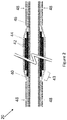
- Radiopaque marker tubing 42 extend over a portion of the innermost tubing 40 of the leaflet braces seen in FIG. 2 . These layers widen the diameter of the leaflet brace 18, 20 to form an abutment 43 along with tubing 44. Abutment 43 stops the fastening catheter 22, 24 from moving further along the leaflet brace during the fastening step.
- the radiopaque marker tubing 42 also allows practitioners to more easily fluoroscopically monitor the position of the leaflet braces as they are arranged behind the anterior and posterior leaflets 6, 7.
- tissue ingrowth tubing 44 can cover the radiopaque marker tubing 42 of the leaflet braces 18, 20.
- the tissue ingrowth tubing 44 extends in both directions past the radiopaque marker tubing 42. It can be a porous or filamentous material that encourages fixation of the leaflet brace to the tissue behind the leaflets.
- the tissue ingrowth tubing 44 can be a multi-filament PTFE yarn.
- the leaflet braces 18, 20 can have a shortening mechanism to allow removal of excess tubing during the mitral valve procedure.
- tear notches 48 can be provided as seen FIG. 2 . These tear notches 48 create weak points that allow excess tubing to be pulled off of the leaflet braces and slid back up the transseptal introducer sheath 2.
- Shrink tubing 46 can extend over the tissue ingrowth tubing 44 anywhere that tissue ingrowth is not desired. This can, for example, prevent the yarn from fraying after the ends are torn.
- FIGS. 3A-3E depict the structural details of exemplary fastening catheters 22, fasteners 26, and the process of fastening the leaflet braces 18, 20.
- the exemplary fastener 26 depicted in FIG. 3A has an elongate fastener body 50 with rounded ends, two locking tab rings 54 positioned inward from the edge of the fastener body, and locking tabs 56 arranged circumferentially inside each locking tab ring 54 and defining spaces through which the leaflet braces 18, 20 can move.
- the locking tabs taper slightly as they extend inward and away from the fastener body 50. In the implementation depicted in FIG. 3A , there are 4 locking tabs per locking tab ring.
- the fasteners 26 can have fewer - such as 2 - locking tabs or more - such as 16 - locking tabs.
- the fasteners can secure the leaflet braces 18, 20 using other mechanisms, such as screws, clips, latches or knots.
- the fastener 26 can be cut from sheet metal with a laser or other cutting techniques.
- the fastener 26 can be a shape-memory metal, such as Nitinol.
- the fastener 26 can be stainless steel or other metals acceptable for use in implantable medical devices.
- the body 50 of the fastener 26 can be secured to the distal face 58 of the fastening catheter 22 using suture 64.
- Fastening catheter lumens 60 slide down over the leaflet braces 18, 20, as shown in FIG. 3B .
- the fastening catheter 22 continues to push the fastener 26 along the leaflet braces 18, 20 until it reaches the abutment 43, as in FIG. 3C .
- Locking tabs 56 catch on the wider section of leaflet braces 18, 22 and prevent it from slipping backward.
- a practitioner can remove the excess tubing from the leaflet braces by pulling at the ends.
- the polymers tear at the tear notches 48, and the excess can be retracted back up the transseptal introducer sheath 2, as shown in FIG. 3D .
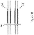
- FIG. 3E shows the leaflet brace 20 after the fasteners are released and the fastening catheter is withdrawn.
- the physician releases one end of the suture 64 and pulls on the other end.
- the suture slides over the fastener body 50 and back up the transseptal introducer sheath 2. This releases the fastener 26 and the attached leaflet braces 18, 20 from the fastening catheter 22.
- the fastening catheter 22 is then withdrawn up the transseptal introducer sheath 2.
- the sheath 2 can be between 10-50 French, depending on the particular method being performed.
- the sheath 2 can contain both the fastening catheters and the valve delivery catheter simultaneously.
- the introducer sheath 2 can be between 25-50 French.
- FIGS. 4A-E allows for the fastening catheter to be removed prior to entry of the valve delivery catheter.
- the introducer sheath 2 of other implementations can be narrower because they do not have to house multiple catheters simultaneously.
- fasteners 126 can include one or more fastener barbs 166.
- FIG. 4A shows two exemplary fasteners 126 with barbs.
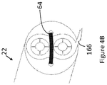
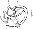
- FIG. 4B shows one of the exemplary fasteners 126 bound to a fastening catheter 22 by a suture 64. After removal of the fastening catheters 22, 24, the barbs protrude as shown in FIG. 4C . The physician can use a steerable catheter to push fastener barbs 166 into the myocardial wall, securing the annular ring formed by the leaflet braces 18, 20.
- FIG. 4D is a cross-sectional schematic of the heart of FIG. 4C after expansion of a balloon inflatable stented heart valve within the native mitral valve.
- Figure 4E is a cross-sectional schematic of a heart after completion of the procedure using the fasteners of FIGS. 4A-4B . Because fastening catheters 22, 24 are removed prior to inserting the valve delivery catheter 28, the diameter of the transseptal introducer sheath 2 can be lower than for the implementation depicted in FIGS. 1A-1I . For example, the diameter of the transseptal introducer sheath can be between 10-30 French.
- fasteners 226 are mounted on a flexible fastener hoop 268.
- the fastener hoop 268 can be between about 50-65 millimeters in diameter.
- the fasteners 226 and hoop 268 can be one piece, as shown in FIG. 5A , or they can be separate pieces joined after forming.
- the fastening hoop 268 can be made of a shape memory material.
- the shape memory material can be Nitinol.
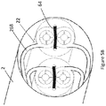
- the fasteners 226 are secured by suture 64 at the distal face 58 of the fastening catheter 22 as shown in FIG. 5B .
- the fastener hoop 268 is folded outside of the fastening catheters but within the transseptal introducer sheath 2.
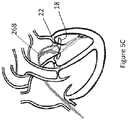
- FIG. 5C depicts the fastening catheters advanced along the leaflet braces 18, 20 with the ends of the fastening hoop 268 still retained in the folded state by the introducer sheath 2.
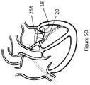
- FIG. 5D shows the fastening hoop 268 in an open position above the mitral valve, while the leaflet braces 18, 20 form an annular ring below the mitral valve.
- the combination of the fastener hoop 268 and the leaflet braces 18, 20 can be used as an annuloplasty device.
- the physician can then deploy a transcatheter heart valve via valve delivery catheter 28 as shown in FIG. 5E .
- the transcatheter heart valve 38 can be mounted on a stent 32. It can be self-expandable, mechanically-expandable or expanded by balloon 30.
- FIG. 5F shows the heart after completion of the procedure using fastener hoop 268.
- fasteners 326 can be mounted directly onto a fastening stent 132.
- FIGS. 6A and 6B illustrate one implementation of the fastener stent 326.
- the fasteners 326 and stent 132 can be one piece, or they can be separate pieces joined after forming.
- the fastening stent 132 can be made of a shape memory material.
- the shape memory material can be Nitinol.
- the leaflet braces 18, 20 are not directly connected to one another, but instead are attached to the fastening stent 132 supporting the heart valve 38 as seen in FIG. 6C .
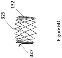
- FIG. 6D shows fasteners 326 mounted directly onto a fastening stent 132.
- This stent also includes an anchor 327.
- the anchor 327 can be used to capture one of the leaflets of the mitral valve as the stent expands.
- the leaflet braces disclosed herein can be used to attach the other leaflet.
- FIG. 6E shows the heart after completion of the procedure using leaflet brace 18, the fastening stent 132, and the anchor 327.
- the anchor can have a petal-like shape, similar to those shown in the '691 patent used to attach to the anterior leaflet, whereas in this implementation they attach to the posterior leaflet.
- FIGS. 7A-7O other implementations of the method can use a sub-commissural catheter 470 to assist in steering the guide wires 9, 11, 14, 16 behind their respective leaflets.
- the sub-commisural catheter 470 as seen in FIG. 7A includes four lumens.
- the first and second lumens house first and second commissural extensions 408 and 410.
- a third lumen houses a valve guide wire 474 terminating in a nose cone 472.
- a fourth lumen houses an internal deflection wire, the anchor point 476 of which can be seen at the distal face of the sub-commissural catheter 470. Pulling on the proximal end of the internal deflection wire causes the sub-commissural catheter to bend.
- FIG. 7B depicts the system in a bent state.
- the bending allows it to curve in the left atrium and enter the left ventricle.
- the physician pulls back on the transseptal introducer sheath 2 to release the commissural extensions 408, 410.
- the extensions extend in opposite directions, such that an end of each can be positioned beneath the two mitral valve commissures.
- the extensions 408, 410 can house right angle guide catheters 413, 415, as shown in FIG. 7C .
- the physician can rotate the guide catheters to face either the anterior or posterior leaflets 6, 7.
- the physician can then deploy ringed guide wires 9, 14 and corresponding snare wires 11, 16 through the right angle guide catheters as shown in FIG. 7D .
- FIGS. 7E-7O depict a procedure using the sub-commissural catheter 470.
- the physician first punctures the interatrial septum 4 using the transseptal introducer sheath 2 such that the distal end of the introducer sheath is within the left atrium, as shown in FIG. 7E .
- the physician advances a valve delivery guidewire 474 through the introducer sheath, through the mitral valve, and into the left ventricle, as seen in FIG. 7F .
- the sub-commissural catheter 470 advances over the guide wire 474 to a point below the valve, as seen in FIG. 7G .
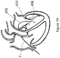
- the physician then pulls back on the transseptal introducer sheath 2 to deploy the commissural extensions 408, 410 as seen in FIG. 7H .
- the catheter 470 is twisted to position one extension end beneath each of the commissures of the mitral valve.
- the physician can position a guide wire in the coronary sinus to assist in the orientation of the commissural extensions.
- the physician then deploys the first ringed guide wire 9 and first snare wire 11 and connects them behind the leaflet.
- the snared distal end of the ringed guide wire 9 is pulled back into the sub-commissural catheter 470 and all the way out of the proximal end of the catheter 470.
- This forms the posterior leaflet wire loop 12 shown in FIG. 7I .
- the physician can then rotate the right angle guide catheters 13, 15 to face the opposite leaflet.
- the physician can then deploy a second set of ring and snare guide wires to form an anterior leaflet wire loop 17, as seen in FIG 7J .
- the sub-commissural catheter 470 and extensions 408, 410 are then removed, leaving behind the wire loops as shown in FIG. 7K .
- Various implementations of fasteners such as (but not limited to) those described herein, can be used to join the two leaflet braces.
- fasteners including screws, latches, clips, or knots can be used to secure the leaflet braces 18, 20.
- FIG. 7N depicts an inflated balloon 30 positioned between the mitral valve leaflets to open a transcatheter heart valve 38.
- the valve can be mechanically-expandable or self-expanding.
- the transcatheter heart valve 38 can be mounted on a stent 32.
- the physician releases the fasteners 26 from the fastening catheters 22, 24 and retracts the fastening catheters and balloon delivery catheter 28 back up the transseptal introducer sheath 2.
- the transseptal introducer sheath 2 is then removed from the patient, completing the procedure as shown in FIG. 7O .
- the leaflet braces 18, 20 can be retrieved back through the transseptal introducer sheath 2. If the leaflet braces are attached to each other by a metal fastener 26 at only one commissure, the entire system can still be retrieved via the transseptal introducer sheath 2.
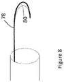
- FIG. 8 depicts a tool for cutting the leaflet braces 18, 20.
- the tool includes a J-curved steel hook 78 with a curved blade 80.
- the physician can advance the hook 78 and position the curved blade 80 over the leaflet brace 18, 20. The physician then pulls the hook 78 back into the catheter with force to sever the brace and abort the procedure.
Landscapes
- Health & Medical Sciences (AREA)
- Cardiology (AREA)
- Engineering & Computer Science (AREA)
- Biomedical Technology (AREA)
- Life Sciences & Earth Sciences (AREA)
- General Health & Medical Sciences (AREA)
- Heart & Thoracic Surgery (AREA)
- Veterinary Medicine (AREA)
- Public Health (AREA)
- Animal Behavior & Ethology (AREA)
- Oral & Maxillofacial Surgery (AREA)
- Transplantation (AREA)
- Vascular Medicine (AREA)
- Prostheses (AREA)
- Surgery (AREA)
- Nuclear Medicine, Radiotherapy & Molecular Imaging (AREA)
- Medical Informatics (AREA)
- Molecular Biology (AREA)
Abstract
Description
- The present application is related to the field of interventional cardiology systems and procedures and, in particular, systems and procedures for heart valve repair.
- Prosthetic devices are commonly used to replace or repair native heart valves that have become inefficient due to age, disease, or congenital reasons. Valve insufficiency, for example, is characterized by a loose or elastic valve structure. This often results in regurgitation wherein the valve leaflets fail to close property ("coapt") and guard against backflow of blood.
- Transvascular techniques have enabled physicians to access the mitral and other valves for repair without open-heart surgery. Valves or annuloplasty rings may be delivered to the site of the valve by catheter and expanded once properly positioned.
- A physician may have difficulty precisely positioning prosthetic devices between the mitral valve leaflets - especially when the mitral valve is insufficient. The prosthetic devices may slip upon expansion within the relatively elastic annulus of the insufficient mitral valve.
- A physician may provide support for the annular ring of the valve during implantation to compensate for mitral valve insufficiency. But, positioning of such support devices in a safe and minimally invasive manner is technically challenging. For example, the chordae tendinae attached to the mitral valve leaflets can interfere with efforts to support the valve or its annulus.
- It is therefore desirable to provide improved systems and methods for supporting replacement valves, especially replacement valves implanted with minimally invasive procedures.
- Disclosed herein are methods and apparatuses for greatly simplifying and improving the outcome of minimally invasive valve procedures - making those procedures much more accessible to less experienced physicians or cardiologists. For example, implementations are applicable to full mitral valve replacement, or to mitral valve annuloplasty. The mitral valve can be accessed by femoral catheterization with a fluoroscopically guided, low-profile catheter. Once the right atrium is accessed and the interatrial septum is punctured, the mitral valve can be approached from the left atrium. This approach avoids contact with the left ventricular outflow tract and the chordae tendineae.
- As part of the method, two leaflet braces circumnavigate the anterior and posterior mitral valve leaflets, forming a loop around each leaflet. Tension in the atrial direction from the catheter keeps the loops tightly wedged under the leaflets for the remainder of the procedure. A fastener joins the ends of each loop to form one annular ring circling the valve under the anterior and posterior leaflets.
- In some implementations, the procedure can be performed with a sub-commissural catheter to assist in steering behind the leaflets. After bracing the individual leaflets, a transcatheter heart valve system can then be deployed between the native leaflets. Expansion of the heart valve traps and sandwiches the native mitral valve leaflets between the valve frame and the leaflet braces. The procedure can be performed in catheterization laboratories and by practitioners with varying levels of expertise.
- A method of supporting a heart valve is provided in one implementation. The method includes looping around a first leaflet of the heart valve. And, applying tension directed through the valve to the first leaflet. The method also includes performing a procedure on the heart valve.
- The method can further comprise looping around a second leaflet of the heart valve and applying tension directed through the valve to the second leaflet.
- The method can also include extending a guide catheter through the valve and advancing a first guide wire through the guide catheter. In this manner, looping around the leaflet includes extending the first guide wire around the first leaflet. Also, a second guide wire could be deployed through the guide catheter and looped around the second leaflet.
- The guide wires can include snare loops and the method includes snaring the snare loop of the guide wires after extending them around the leaflets.
- The method can also include forming first and second leaflet braces. A first leaflet brace extends over the first guide wire and around the first leaflet. Also, a second leaflet brace is extended over the second guide wire and around the second leaflet.
- The method can also include securing adjacent ends of the leaflet braces to each other to form a closed loop, such as a circle. For example, the physician can attach a first pair of adjacent ends using a first leaflet brace and a second pair of adjacent ends using a second leaflet brace. Then, as an exemplary procedure on the heart valve, a replacement heart valve can be expanded within the native heart valve. Expansion for example can include releasing a self-expanding heart valve within the (native) heart valve and against the leaflets (directly) and the leaflet braces (indirectly). The method can also include removing excess tubing from the leaflet braces.
- Advantageously, all of these procedures can occur while the method applies tension to the leaflets for improved results. For example, the tension on the leaflets helps with accurate positioning (and slip avoidance) during expansion of the replacement heart valve.
- The heart valve can be, for example, a mitral heart valve and the method can be used to avoid and preserve the chordae tendinae. Other heart valves might be aortic, tricuspid or pulmonic, or prior replacement heart valves in need of repair.
- In another implementation, a system is disclosed for supporting a heart valve having at least two leaflets. The system can include at least one fastening catheter and at least one leaflet brace. The fastening catheter has a distal end and defines at least two adjacent lumens extending through the distal end. The fastening catheter also includes at least one fastener coupled to the fastening catheter, such as at the distal end. The leaflet brace has an elongate flexible structure configured to extend through one of the lumens of the fastening catheter and around at least one leaflet of the heart valve.
- The elongate flexible structure can include an abutment surface configured to stop advancement of the fastener over the leaflet brace. The elongate flexible structure can also include an inner elastic layer and an outer functional layer. The outer functional layer can be, for example, an ingrowth layer, a radiopaque or a shrink layer. The elongate flexible structure can also include a shortening mechanism, such as a tear notch defined within the elongate flexible structure.
- The system may include a first and second leaflet braces and first and second fastening catheters. A first pair of adjacent ends of the first and second leaflet braces are configured to extend through adjacent lumens of the first fastening catheter. A second pair of adjacent ends of the first and second leaflet braces are configured to extend through adjacent lumens of the second fastening catheter. The fastener of the first fastening catheter is configured to attach together the first pair of adjacent ends. The fastener of the second fastening catheter is configured to attach together the second pair of adjacent ends, thus forming an annular ring encircling the at least one leaflet of the heart valve.
- The fastener can define a pair of adjacent openings configured to align over the two adjacent lumens at the distal end and receive therethrough at least a portion of the leaflet brace. The fastener can also include a plurality of locking tabs extending around the adjacent openings.
- The system can also include a fastener hoop having coupled thereto the fastener of the first fastening catheter and the fastener of the second fastening catheter. The fastener hoop can be circular with the fasteners coupled on the opposite sides of the hoop.
- The system can also include a transseptal introducer sheath configured to deliver the at least one fastening catheter.
- The system can also include one or more barbs coupled to the at least one leaflet brace to help secure the brace to heart tissue.
- The system can also include a prosthetic valve configured to expand within the leaflets of the heart valve and the least one leaflet brace. The expanded prosthetic valve can sandwich the leaflets between the prosthetic valve and the at least one leaflet brace.
- The system can include an elongate coupling member (such as a suture) releasably coupling the fastener to the at least one fastening catheter.
-
-
Figure 1A is a cross-sectional schematic of a heart undergoing a minimally invasive mitral valve procedure including introduction of a catheter via a transseptal access point. -
Figure 1B is a cross-sectional schematic of the heart fromFigure 1A with introduction of a guide catheter. -
Figure 1C is a cross-sectional schematic of the heart fromFigure 1A with introduction of a snare catheter and formation of a loop around the posterior leaflet. -
Figure 1D is a cross-sectional schematic of the heart fromFigure 1A with introduction of a second guide catheter. -
Figure 1E is a cross-sectional schematic of the heart fromFigure 1A with introduction of a second snare catheter and formation of a loop around the anterior leaflet. -
Figure 1F is a cross-sectional schematic of the heart fromFigure 1A with introduction of first and second leaflet braces over the loops. -
Figure 1G is a cross-sectional schematic of the heart fromFigure 1A with introduction of fastening catheters to secure the loops at either end. -
Figure 1H is a cross-sectional schematic of the heart fromFigure 1A after introduction and expansion of a balloon inflatable stented heart valve within the native mitral valve. -
Figure 1I is a cross-sectional schematic of the heart fromFigure 1A after completion of the procedure. -
Figure 2 shows a cross-section of a leaflet brace. -
Figure 3A shows a perspective view of a distal end of a pair of fastening catheters. -
Figures 3B and3F show a cross section and perspective view of the fastening catheter and fastener ofFigure 3A engaged with a leaflet brace. -
Figure 3C shows a cross-section of the fastening catheter and fastener ofFigure 3A after advancement of the fastening catheter down the leaflet brace. -
Figure 3D shows a cross-section of the fastening catheter, fastener and leaflet brace ofFigure 3C after removal of the leaflet brace ends. -
Figures 3E and3G shows a cross-section and perspective view of the fastener and leaflet brace ofFigures 3A-3D after removal of the fastening catheter. -
Figure 4A shows a perspective view of two fasteners having barbs. -
Figure 4B shows a perspective view of one of the fasteners ofFigure 4A bound to a fastening catheter. -
Figure 4C is a cross-sectional schematic of a heart having a leaflet brace ring fastened by the fasteners ofFigures 4A and4B . -
Figure 4D is a cross-sectional schematic of the heart ofFigure 4C after expansion of a balloon inflatable stented heart valve within the native mitral valve. -
Figure 4E is a cross-sectional schematic of a heart after completion of the procedure using the fasteners ofFigures 4A-4B . -
Figure 5A shows a top view of two fasteners mounted on a fastener hoop. -
Figure 5B shows a perspective view of the fasteners and fastener hoop ofFigure 5A in a transseptal introducer sheath. -
Figure 5C is a cross-sectional schematic of the introduction of the fastening hoop ofFigures 5A-5B during a mitral valve procedure. -
Figure 5D is a cross-sectional schematic of the heart after expansion of the fastening hoop ofFigure 5C . -
Figure 5E is a cross-sectional schematic of the heart ofFigure 5D after expansion of a balloon inflatable stented heart valve within the native mitral valve. -
Figure 5F is a cross-sectional schematic of the heart after completion of the procedure using the fastening hoop ofFigures 5A-5D . -
Figure 6A is perspective view of a fastener stent. -
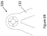
Figure 6B is an enlarged top view of the boxed area ofFigure 6A showing the detail of a fastener on the fastener stent. -
Figure 6C is a cross-sectional schematic of a heart after undergoing a minimally invasive mitral valve procedure with the fastener stent ofFigure 6A . -
Figure 6D is a perspective view of the fastener stent ofFigure 6A . -
Figure 6E is a cross-sectional schematic of a heart with the leaflet brace, the fastener stent and an anchor. -
Figure 7A is a perspective view of a sub-commissural catheter in a transseptal introducer sheath. -
Figure 7B shows perspective views of the sub-commissural catheter ofFigure 7A with sub-commissural extensions in both retracted and deployed states. -
Figure 7C is a perspective view of the sub-commissural catheter ofFigure 7B with right angle guide catheters deployed. -
Figure 7D is a perspective view of the sub-commissural catheter ofFigure 7C with ringed and snare guide wires deployed. -
Figure 7E is a cross-sectional schematic of a heart undergoing a minimally invasive mitral valve procedure after introduction of the transseptal introducer sheath ofFigure 7A-7D . -
Figure 7F is a cross-sectional schematic of the heart ofFigure 7E after introduction of a valve guide wire. -
Figure 7G is a cross-sectional schematic of the heart ofFigure 7F after introduction of a sub-commissural catheter over the valve guide wire. -
Figure 7H is a cross-sectional schematic of the heart ofFigure 7G with the commissural extensions deployed from the sub-commissural catheter. -
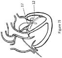
Figure 7I is a cross-sectional schematic of the heart ofFigure 7H after formation of a guide wire loop around the posterior leaflet. -
Figure 7J is a cross-sectional schematic of the heart ofFigure 7I after formation of a guide wire loop around the anterior leaflet. -
Figure 7K is a cross-sectional schematic of the heart ofFigure 7J after retraction of the sub-commissural catheter. -
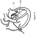
Figure 7L is a cross-sectional schematic of the heart ofFigure 7K after deployment of the leaflet braces around the guide wire loops. -
Figure 7M is a cross-sectional schematic of the heart ofFigure 7L after introduction of fastening catheters over the leaflet braces. -
Figure 7N is a cross-sectional schematic of the heart ofFigure 7M after expansion of a balloon inflatable stented heart valve. -
Figure 7O is a cross-sectional schematic of the heart ofFigure 7E-7N after completion of a minimally invasive mitral valve procedure with the sub-commissural catheter and transseptal introducer sheath ofFigure 7A-D . -
Figure 8 shows a schematic of a tool for cutting leaflet braces. - The following description of certain examples of a medical system (e.g., catheters and implants) should not be used to limit the scope of the medical system. Other examples, features, aspects, embodiments, and advantages of the medical system will become apparent to those skilled in the art from the following description. As will be realized, the medical system is capable of additional aspects, all without departing from the spirit of the medical apparatus. Accordingly, the drawings and descriptions should be regarded as illustrative in nature and not restrictive.
- For purposes of this description, certain aspects, advantages, and novel features of the embodiments of this disclosure are described herein. The described methods, systems, and apparatus should not be construed as limiting in any way. Instead, the present disclosure is directed toward all novel and nonobvious features and aspects of the various disclosed embodiments, alone and in various combinations and sub-combinations with one another. The disclosed methods, systems, and apparatus are not limited to any specific aspect, feature, or combination thereof, nor do the disclosed methods, systems, and apparatus require that any one or more specific advantages be present or problems be solved.
- Features, integers, characteristics, compounds, chemical moieties, or groups described in conjunction with a particular aspect, embodiment or example of the invention are to be understood to be applicable to any other aspect, embodiment or example described herein unless incompatible therewith. All of the features disclosed in this specification (including any accompanying claims, abstract, and drawings), and/or all of the steps of any method or process so disclosed, can be combined in any combination, except combinations where at least some of such features and/or steps are mutually exclusive. The invention is not restricted to the details of any foregoing embodiments. The invention extends to any novel one, or any novel combination, of the features disclosed in this specification (including any accompanying claims, abstract, and drawings), or to any novel one, or any novel combination, of the steps of any method or process so disclosed.
- It should be appreciated that any patent, publication, or other disclosure material, in whole or in part, that is said to be incorporated by reference herein is incorporated herein only to the extent that the incorporated material does not conflict with existing definitions, statements, or other disclosure material set forth in this disclosure. As such, and to the extent necessary, the disclosure as explicitly set forth herein supersedes any conflicting material incorporated herein by reference. Any material, or portion thereof, that is said to be incorporated by reference herein, but which conflicts with existing definitions, statements, or other disclosure material set forth herein will only be incorporated to the extent that no conflict arises between that incorporated material and the existing disclosure material.
- Apparatuses and methods for performing minimally invasive mitral valve procedures are disclosed herein. For example, these apparatuses and methods can be applied to full mitral valve replacement, or to mitral valve annuloplasty. Although particularly suited for mitral valves, these apparatuses and methods can also be applied to other valves. The procedures can be performed in catheterization laboratories and by practitioners with varying levels of expertise.
- For illustrative purposes, certain embodiments of the system are described as being used in connection with a trans-catheter heart valve (THV). For example, the systems and methods may be employed with the balloon-expandable THV described in
U.S. Patent Application Publication No. 8,764,820 , which is hereby expressly incorporated herein by reference. It should be understood, however, that the systems and methods should not be limited to use with balloon-expandable THVs. Instead, embodiments of the disclosed systems and methods can be used to secure a wide variety of THVs delivered through a variety of mechanisms (e.g., self-expanding heart valves, mechanically-expanding heart valves, other balloon-expanding heart valves, and the like). For instance, any of the embodiments described inU.S. Pat. No. 6,730,118 can be used with embodiments of the disclosed system.U.S. Pat. No. 6,730,118 is hereby expressly incorporated herein by reference. - Access to the mitral valve can be obtained using femoral catheterization with a fluoroscopically guided, low-profile catheter. For example, the right atrium is accessed and the interatrial septum punctured to get to the left atrium. Then the mitral valve is approached through the left atrium. Advantageously, this approach avoids contact with the left ventricular outflow tract and the chordae tendineae.
- Two leaflet braces are extended over guide wires to form semicircular loops that circumnavigate the anterior and posterior mitral valve leaflets. Tension is applied to the catheter from the atrial direction to keep the leaflet braces tightly wedged under the leaflets for the remainder of the procedure. A fastener joins the ends of each loop to create one annular ring encircling the valve under the anterior and posterior leaflets.
- In some implementations, the procedure can be performed with a sub-commissural catheter to assist in steering behind the leaflets. In certain implementations, the remaining catheters can be separated from the leaflet braces after implantation, leaving the annular ring in place behind the leaflets. The annular ring formed can serve as part of an annuloplasty device. Alternatively, a transcatheter heart valve system can then be deployed between the native leaflets. Expansion of the heart valve traps and sandwiches the native mitral valve leaflets between the valve frame and the leaflet braces.
- To begin the transseptal procedure, a physician punctures the septum with a needle and advances a guide wire through the needle. The physician then retrieves the needle, leaving a guide wire across the septum. The physician then advances a dilator with a cone shaped distal end over the guide wire and across the septum. The physician then advances a
transseptal introducer sheath 2 over the dilator, through the interatrial septum 4 and toward the anterior andposterior leaflets FIG. 1A . - As in
FIG. 1B , a first doublebend guide catheter 8 extends from theintroducer sheath 2 to cannulate the mitral valve at the posteromedial commissure. The physician then advances a first guide wire with a ringed end throughguide catheter 8 and around theposterior leaflet 7 towards the anterolateral commissure. Afirst snare catheter 10 then cannulates the mitral valve at the anterolateral commissure. A first snare guide wire positioned at the distal end of thesnare catheter 10 captures the first ringed guide wire and pulls it out, so that the guide wire circumvents theposterior leaflet 7 at the base of the mitral valve, as inFIG. 1C . This forms a posteriorleaflet wire loop 12. - The process is repeated in
FIGS. 1D and1E around theanterior leaflet 6 using a second doublebend guide catheter 13, a second ringed guide wire (not shown), asecond snare catheter 15, and a second snare guide wire (not shown). This forms an anteriorleaflet wire loop 17. - The physician retracts the guide and snare catheters, leaving the wire loops in place. The physician then slides two tubular leaflet braces 18, 20 over the loops such that they are positioned around the posterior and anterior
wire leaflet loops FIG. 1F . The structure of the braces is shown inFIG. 2 and will be described in greater detail below. - The physician then slides anterolateral and a
posteromedial fastening catheters FIG. 1G . In particular, theposteromedial fastening catheter 22 runs up the two ringedguide wires 9, 14 and over the leaflet brace ends located at the posteromedial side of the valve. Theanterolateral fastening catheter 24 runs up the two snaredguide wires -
Fasteners 26 located at the distal faces of thefastening catheters FIGS. 3A ,4A ,5A , and6A , and are described in greater detail below. - The physician then removes excess tubing from the leaflet braces and retracts the excess tubing back through the
transseptal introducer sheath 2. The two braces now form one annular ring circling the valve under the anterior andposterior leaflets FIG. 1G . Bothfastening catheters - The physician can then guide a
valve delivery catheter 28 through thetransseptal introducer sheath 2 and into the space betweenmitral valve leaflets transcatheter heart valve 38 can be mounted on astent 32. It can be self-expandable, mechanically-expandable, or expanded byballoon 30 as shown inFIG. 1H . Expansion of theheart valve 38 traps and sandwiches the nativemitral valve leaflets fasteners 26 from thefastening catheters suture 64 that binds them to the fastening catheter (seeFIGS. 3A-3E ). The physician then retracts the fastening catheters andballoon delivery catheter 28 back through the transseptal introducer sheath. Finally, thetransseptal introducer sheath 2 is removed from the patient.FIG. 1I shows the heart after the procedure with the surgical devices in place. - As shown in
FIG. 2 , stacked layers of polymer tubing form the exemplary leaflet braces 18, 20. The leaflet braces 18, 20 can be formed using standard catheter extrusion and braiding techniques. In this implementation, theinnermost tubing 40 can be made from an elastic polymer such as PTFE or PU, or other elastic polymers suitable for medical device tubing. Theinnermost tubing 40 can have 10-100% elongation at failure. For example, theinnermost tubing 40 can have about 20% elongation at failure. - Two or more layers of
radiopaque marker tubing 42 extend over a portion of theinnermost tubing 40 of the leaflet braces seen inFIG. 2 . These layers widen the diameter of theleaflet brace abutment 43 along withtubing 44.Abutment 43 stops thefastening catheter radiopaque marker tubing 42 also allows practitioners to more easily fluoroscopically monitor the position of the leaflet braces as they are arranged behind the anterior andposterior leaflets - As shown in
FIG. 2 , one or more layers oftissue ingrowth tubing 44 can cover theradiopaque marker tubing 42 of the leaflet braces 18, 20. Thetissue ingrowth tubing 44 extends in both directions past theradiopaque marker tubing 42. It can be a porous or filamentous material that encourages fixation of the leaflet brace to the tissue behind the leaflets. For example, thetissue ingrowth tubing 44 can be a multi-filament PTFE yarn. - The leaflet braces 18, 20 can have a shortening mechanism to allow removal of excess tubing during the mitral valve procedure. For example, tear
notches 48 can be provided as seenFIG. 2 . These tearnotches 48 create weak points that allow excess tubing to be pulled off of the leaflet braces and slid back up thetransseptal introducer sheath 2. Shrinktubing 46 can extend over thetissue ingrowth tubing 44 anywhere that tissue ingrowth is not desired. This can, for example, prevent the yarn from fraying after the ends are torn. -
FIGS. 3A-3E depict the structural details ofexemplary fastening catheters 22,fasteners 26, and the process of fastening the leaflet braces 18, 20. Theexemplary fastener 26 depicted inFIG. 3A has anelongate fastener body 50 with rounded ends, two locking tab rings 54 positioned inward from the edge of the fastener body, and lockingtabs 56 arranged circumferentially inside each lockingtab ring 54 and defining spaces through which the leaflet braces 18, 20 can move. The locking tabs taper slightly as they extend inward and away from thefastener body 50. In the implementation depicted inFIG. 3A , there are 4 locking tabs per locking tab ring. However, thefasteners 26 can have fewer - such as 2 - locking tabs or more - such as 16 - locking tabs. Alternatively, the fasteners can secure the leaflet braces 18, 20 using other mechanisms, such as screws, clips, latches or knots. Thefastener 26 can be cut from sheet metal with a laser or other cutting techniques. In some implementations, thefastener 26 can be a shape-memory metal, such as Nitinol. In other implementations, thefastener 26 can be stainless steel or other metals acceptable for use in implantable medical devices. - As shown in
FIG. 3A , thebody 50 of thefastener 26 can be secured to thedistal face 58 of thefastening catheter 22 usingsuture 64. Fastening catheter lumens 60 slide down over the leaflet braces 18, 20, as shown inFIG. 3B . Thefastening catheter 22 continues to push thefastener 26 along the leaflet braces 18, 20 until it reaches theabutment 43, as inFIG. 3C . Lockingtabs 56 catch on the wider section of leaflet braces 18, 22 and prevent it from slipping backward. A practitioner can remove the excess tubing from the leaflet braces by pulling at the ends. The polymers tear at thetear notches 48, and the excess can be retracted back up thetransseptal introducer sheath 2, as shown inFIG. 3D . -
FIG. 3E shows theleaflet brace 20 after the fasteners are released and the fastening catheter is withdrawn. To release the fastener from the fastening catheter, the physician releases one end of thesuture 64 and pulls on the other end. The suture slides over thefastener body 50 and back up thetransseptal introducer sheath 2. This releases thefastener 26 and the attached leaflet braces 18, 20 from thefastening catheter 22. Thefastening catheter 22 is then withdrawn up thetransseptal introducer sheath 2. - The
sheath 2 can be between 10-50 French, depending on the particular method being performed. For example, in the implementation depicted byFIGS 1A-1I , thesheath 2 can contain both the fastening catheters and the valve delivery catheter simultaneously. In this case theintroducer sheath 2 can be between 25-50 French. The implementation ofFIGS. 4A-E allows for the fastening catheter to be removed prior to entry of the valve delivery catheter. Thus, theintroducer sheath 2 of other implementations can be narrower because they do not have to house multiple catheters simultaneously. - In the implementation depicted in
FIGS. 4A-E ,fasteners 126 can include one ormore fastener barbs 166.FIG. 4A shows twoexemplary fasteners 126 with barbs.FIG. 4B shows one of theexemplary fasteners 126 bound to afastening catheter 22 by asuture 64. After removal of thefastening catheters FIG. 4C . The physician can use a steerable catheter to pushfastener barbs 166 into the myocardial wall, securing the annular ring formed by the leaflet braces 18, 20. - The physician can then deploy a
transcatheter heart valve 38 via avalve delivery catheter 28. The expansion of thevalve 38 securesbarbs 166 within the myocardial tissue.Figure 4D is a cross-sectional schematic of the heart ofFIG. 4C after expansion of a balloon inflatable stented heart valve within the native mitral valve.Figure 4E is a cross-sectional schematic of a heart after completion of the procedure using the fasteners ofFIGS. 4A-4B . Becausefastening catheters valve delivery catheter 28, the diameter of thetransseptal introducer sheath 2 can be lower than for the implementation depicted inFIGS. 1A-1I . For example, the diameter of the transseptal introducer sheath can be between 10-30 French. - In the implementation depicted in
FIGS. 5A-5F ,fasteners 226 are mounted on aflexible fastener hoop 268. Thefastener hoop 268 can be between about 50-65 millimeters in diameter. Thefasteners 226 andhoop 268 can be one piece, as shown inFIG. 5A , or they can be separate pieces joined after forming. Thefastening hoop 268 can be made of a shape memory material. For example, the shape memory material can be Nitinol. - During deployment, the
fasteners 226 are secured bysuture 64 at thedistal face 58 of thefastening catheter 22 as shown inFIG. 5B . Thefastener hoop 268 is folded outside of the fastening catheters but within thetransseptal introducer sheath 2. -
FIG. 5C depicts the fastening catheters advanced along the leaflet braces 18, 20 with the ends of thefastening hoop 268 still retained in the folded state by theintroducer sheath 2. Once thefastening catheters introducer sheath 2, the ends of thefastening hoop 268 open above the mitral valve while thefasteners 226 secure the ends of the leaflet braces 18, 20. The physician then releases thefastening hoop 268 and removes thefastening catheters -
FIG. 5D shows thefastening hoop 268 in an open position above the mitral valve, while the leaflet braces 18, 20 form an annular ring below the mitral valve. The combination of thefastener hoop 268 and the leaflet braces 18, 20 can be used as an annuloplasty device. Alternatively, the physician can then deploy a transcatheter heart valve viavalve delivery catheter 28 as shown inFIG. 5E . As above for other implementations, thetranscatheter heart valve 38 can be mounted on astent 32. It can be self-expandable, mechanically-expandable or expanded byballoon 30.FIG. 5F shows the heart after completion of the procedure usingfastener hoop 268. - In another implementation, such as the one seen in
FIGS. 6A-6C ,fasteners 326 can be mounted directly onto afastening stent 132.FIGS. 6A and6B illustrate one implementation of thefastener stent 326. When deployed, thefasteners 326 are positioned on the atrial edge of thestent 132. Thefasteners 326 andstent 132 can be one piece, or they can be separate pieces joined after forming. Thefastening stent 132 can be made of a shape memory material. For example, the shape memory material can be Nitinol. In this implementation, the leaflet braces 18, 20 are not directly connected to one another, but instead are attached to thefastening stent 132 supporting theheart valve 38 as seen inFIG. 6C . - For this implementation, securement of just one leaflet can be sufficient.
FIG. 6D showsfasteners 326 mounted directly onto afastening stent 132. This stent also includes ananchor 327. As described in the disclosure ofU.S. Patent 8,926,691 (which is hereby incorporated herein by reference), theanchor 327 can be used to capture one of the leaflets of the mitral valve as the stent expands. The leaflet braces disclosed herein can be used to attach the other leaflet.FIG. 6E shows the heart after completion of the procedure usingleaflet brace 18, thefastening stent 132, and theanchor 327. The anchor can have a petal-like shape, similar to those shown in the '691 patent used to attach to the anterior leaflet, whereas in this implementation they attach to the posterior leaflet. - As shown in
FIGS. 7A-7O , other implementations of the method can use asub-commissural catheter 470 to assist in steering theguide wires sub-commisural catheter 470 as seen inFIG. 7A includes four lumens. The first and second lumens house first and secondcommissural extensions valve guide wire 474 terminating in anose cone 472. A fourth lumen houses an internal deflection wire, theanchor point 476 of which can be seen at the distal face of thesub-commissural catheter 470. Pulling on the proximal end of the internal deflection wire causes the sub-commissural catheter to bend. -
FIG. 7B depicts the system in a bent state. The bending allows it to curve in the left atrium and enter the left ventricle. The physician pulls back on thetransseptal introducer sheath 2 to release thecommissural extensions - The
extensions angle guide catheters FIG. 7C . The physician can rotate the guide catheters to face either the anterior orposterior leaflets guide wires 9, 14 andcorresponding snare wires 11, 16 through the right angle guide catheters as shown inFIG. 7D . -
FIGS. 7E-7O depict a procedure using thesub-commissural catheter 470. The physician first punctures the interatrial septum 4 using thetransseptal introducer sheath 2 such that the distal end of the introducer sheath is within the left atrium, as shown inFIG. 7E . The physician then advances avalve delivery guidewire 474 through the introducer sheath, through the mitral valve, and into the left ventricle, as seen inFIG. 7F . Thesub-commissural catheter 470 advances over theguide wire 474 to a point below the valve, as seen inFIG. 7G . The physician then pulls back on thetransseptal introducer sheath 2 to deploy thecommissural extensions FIG. 7H . Thecatheter 470 is twisted to position one extension end beneath each of the commissures of the mitral valve. The physician can position a guide wire in the coronary sinus to assist in the orientation of the commissural extensions. - The physician then deploys the first ringed
guide wire 9 andfirst snare wire 11 and connects them behind the leaflet. The snared distal end of the ringedguide wire 9 is pulled back into thesub-commissural catheter 470 and all the way out of the proximal end of thecatheter 470. This forms the posteriorleaflet wire loop 12 shown inFIG. 7I . The physician can then rotate the rightangle guide catheters leaflet wire loop 17, as seen inFIG 7J . Thesub-commissural catheter 470 andextensions FIG. 7K . - The physician then slides the radiopaque leaflet braces 18, 20 down the guide wires and positions them along posterior and anterior
leaflet wire loops FIG. 7L . He or she then moves the anterolateral and aposteromedial fastening catheters FIG. 7M . Various implementations of fasteners, such as (but not limited to) those described herein, can be used to join the two leaflet braces. For example, fasteners including screws, latches, clips, or knots can be used to secure the leaflet braces 18, 20. - The physician can then tear away the excess tubing from the leaflet braces and retract it back through the
transseptal introducer sheath 2. The two braces now form one annular ring circling the valve under the anterior andposterior leaflets valve delivery catheter 28 and deploy atranscatheter heart valve 38.FIG. 7N depicts aninflated balloon 30 positioned between the mitral valve leaflets to open atranscatheter heart valve 38. Alternatively, or in addition, the valve can be mechanically-expandable or self-expanding. Thetranscatheter heart valve 38 can be mounted on astent 32. - After delivering the valve, the physician releases the
fasteners 26 from thefastening catheters balloon delivery catheter 28 back up thetransseptal introducer sheath 2. Thetransseptal introducer sheath 2 is then removed from the patient, completing the procedure as shown inFIG. 7O . - In the event that the procedure must be prematurely aborted, the leaflet braces 18, 20 can be retrieved back through the
transseptal introducer sheath 2. If the leaflet braces are attached to each other by ametal fastener 26 at only one commissure, the entire system can still be retrieved via thetransseptal introducer sheath 2. - If the braces are attached to each other at both commissures and/or secured to the myocardium with barb, they can be cut to be retrieved.
FIG. 8 depicts a tool for cutting the leaflet braces 18, 20. The tool includes a J-curved steel hook 78 with acurved blade 80. Using a tube cutting catheter and fluoroscopic imaging techniques, the physician can advance thehook 78 and position thecurved blade 80 over theleaflet brace hook 78 back into the catheter with force to sever the brace and abort the procedure. - Although the disclosure has been shown and described with respect to a certain embodiment or embodiments, it is obvious that equivalent alterations and modifications will occur to others skilled in the art upon the reading and understanding of this specification and the annexed drawings. In particular regard to the various functions performed by the above described elements (components, assemblies, devices, compositions, etc.), the terms (including a reference to a "means") used to describe such elements are intended to correspond, unless otherwise indicated, to any element which performs the specified function of the described element (i.e., that is functionally equivalent), even though not structurally equivalent to the disclosed structure which performs the function in the herein illustrated exemplary embodiment or embodiments. In addition, while a particular feature of the disclosure may have been described above with respect to only one or more of several illustrated embodiments, such feature may be combined with one or more other features of the other embodiments, as may be desired and advantageous for any given or particular application.
- The application further comprises the following embodiments:
- In a first embodiment, a method of supporting a heart valve comprises looping around a first leaflet of the heart valve; applying tension directed through the valve to the first leaflet; and performing a procedure on the heart valve.
- In a second embodiment, the method according to the first embodiment further comprises looping around a second leaflet of the heart valve and applying tension directed through the valve to the second leaflet.
- In a third embodiment, the method according to the first and second embodiments further comprises extending at least one guide catheter through the valve.
- In a fourth embodiment, the method according to the third embodiment further comprises advancing a first guide wire through the at least one guide catheter and wherein looping around the first leaflet includes extending the first guide wire around the first leaflet.
- In a fifth embodiment, the method according to the third and fourth embodiments further comprises advancing a second guide wire through the at least one guide catheter and looping around the second leaflet includes extending the second guide wire around the second leaflet.
- In a sixth embodiment of the method according to the fifth embodiment, the first and second guide wires each include a snare loop and wherein looping around the first and second leaflets includes snaring the snare loop of the first and second guide wires.
- In a seventh embodiment, the method according to the fifth and sixth embodiments further comprises extending a first leaflet brace over the first guide wire and around the first leaflet and extending a second leaflet brace over the second guide wire and around the second leaflet.
- In an eighth embodiment, the method according to the seventh embodiment further comprises securing adjacent ends of the first leaflet brace and second leaflet brace to each other to form a closed loop.
- In a ninth embodiment of the method according to the eighth embodiment, securing adjacent ends includes attaching a first fastener to a first pair of adjacent ends of the first and second leaflet braces and attaching a second fastener to a second pair of adjacent ends of the first and second leaflet braces.
- In a tenth embodiment, the method according to the seventh to ninth embodiments further comprises removing excess tubing from the leaflet braces.
- In an eleventh embodiment of the method according to the seventh to ninth embodiments, applying tension to the first and second valve leaflets includes applying tension to the first and second leaflet braces.
- In a twelfth embodiment of the method according to the first to eleventh embodiments, performing a procedure on the heart valve includes expanding a replacement heart valve within the heart valve.
- In a thirteenth embodiment of the method according to the twelfth embodiment, expanding the replacement heart valve includes releasing a self-expanding heart valve within the heart valve.
- In a fourteenth embodiment of the method according to the twelfth embodiment, expanding the replacement heart valve includes expanding the replacement heart valve against the leaflets and the leaflet braces.
- In a fifteenth embodiment of the method according to the thirteenth and fourteenth embodiments, expanding is performed while applying tension to leaflets.
- In a sixteenth embodiment of the method according to the first to fifteenth embodiments, the heart valve is a native mitral valve.
- In a seventeenth embodiment, a system for supporting a heart valve having at least two leaflets comprises at least one fastening catheter having a distal end and defining at least two adjacent lumens extending through the distal end and including at least one fastener coupled to the fastening catheter; and at least one leaflet brace having an elongate flexible structure configured to extend through one of the lumens and around at least one leaflet of the heart valve.
- In an eighteenth embodiment of the system according to the seventeenth embodiment, the elongate flexible structure includes an abutment surface configured to stop advancement of the fastener over the leaflet brace.
- In a nineteenth embodiment of the system according to the seventeenth to eighteenth embodiments, the elongate flexible structure includes an inner elastic layer and an outer functional layer.
- In a twentieth embodiment of the system according to the nineteenth embodiment, the outer functional layer is one of an ingrowth layer or a radiopaque layer or a shrink layer.
- In a twenty-first embodiment of the system according to the seventeenth to the twentieth embodiments, the elongate flexible structure includes a shortening mechanism.
- In a twenty-second embodiment of the system according to the twenty-first embodiment, the shortening mechanism includes at least one tear notch defined within the elongate flexible structure.
- In a twenty-third embodiment of the system according to the seventeenth embodiment, the at least one leaflet brace includes a first leaflet brace and a second leaflet brace and wherein the at least one fastening catheter includes a first fastening catheter and a second fastening catheter and wherein a first pair of adjacent ends of the first and second leaflet braces are configured to extend through the adjacent lumens of the first fastening catheter and a second pair of adjacent ends of the first and second leaflet braces are configured to extend through the adjacent lumens of the second fastening catheter.
- In a twenty-fourth embodiment of the system according to the twenty-third embodiment, the fastener of the first fastening catheter is configured to attach together the first pair of adjacent ends and the fastener of the second fastening catheter is configured to attach together the second pair of adjacent ends to form an annular loop encircling the at least one leaflet of the heart valve.
- In a twenty-fifth embodiment of the system according to the seventeenth to twenty-fourth embodiments, the fastener defines a pair of adjacent openings configured to align over the two adjacent lumens at the distal end and receive therethrough at least a portion of the leaflet brace.
- In a twenty-sixth embodiment of the system according to the twenty-fifth embodiment, the fastener includes a plurality of locking tabs extending around the adjacent openings.
- In a twenty-seventh embodiment, the system according to the twenty-third to the twenty-fourth embodiments further comprises a fastener hoop having coupled thereto the fastener of the first fastening catheter and the fastener of the second fastening catheter.
- In a twenty-eighth embodiment of the system according to the twenty-seventh embodiment, the fastener hoop is circular and the fastener of the first fastening catheter is coupled to an opposite side of the fastener hoop from the fastener of the second fastening catheter.
- In a twenty-ninth embodiment, the system according to the seventeenth to twenty-eighth embodiments further comprises a transseptal introducer sheath configured to deliver the at least one fastening catheter.
- In a thirtieth embodiment, the system according to the seventeenth to twenty-ninth embodiments further comprises at least one barb coupled to the at least one leaflet brace.
- In a thirty-first embodiment, the system according to the seventeenth to thirtieth embodiments further comprises a prosthetic heart valve configured to expand within the leaflets of the heart valve and the at least one leaflet brace so as to sandwich the leaflets between the prosthetic heart valve and the at least one leaflet brace.
- In a thirty-second embodiment, the system according to the seventeenth to thirty-first embodiments further comprises an elongate coupling member releaseably coupling the fastener to the at least one fastening catheter.
Claims (12)
- A system for repairing a native heart valve having at least first and second native leaflets, the system comprising:a prosthetic heart valve;a first leaflet brace having a first end portion and a second end portion, and a second leaflet brace having a first end portion and a second end portion, wherein each of the first and second leaflet braces forms an elongate flexible structure and is configured to extend partially around the first native leaflet;a first fastener configured to join the first end portion of the first leaflet brace and the first end portion of the second leaflet brace and a second fastener configured to join the second end portion of the first leaflet brace and the second end portion of the second leaflet braceso that the first and second leaflet braces encircle the first and second native leaflets,wherein the prosthetic heart valve is configured to expand within the at least first and second leaflets of the native heart valve and the first and second leaflet braces so as to sandwich the at least first and second leaflets between the prosthetic heart valve and the first and second leaflet braces.
- The system of claim 1, wherein the first fastener comprises first and second openings and is configured to receive the first end portion of the first leaflet brace and the first end portion of the second leaflet brace.
- The system of claim 2, wherein the second fastener comprises first and second openings and is configured receive the second end portion of the first leaflet brace and the second end portion of the second leaflet brace.
- The system of claim 2, wherein the first fastener comprises a plurality of locking tabs arranged within the first and second openings and configured to engage outer surfaces of the first and second leaflet braces.
- The system of claim 3, wherein the second fastener comprises a plurality of locking tabs arranged within the first and second openings and configured to engage outer surfaces of the first and second leaflet braces.
- The system of claims 1 to 5, wherein the first fastener comprises one or more fastener barbs configured to be pushed into adjacent tissue in the heart.
- The system of claims 1 to 6, wherein the prosthetic heart valve is self-expanding.
- The system of claims 1 to 7, wherein each of the first and second leaflet braces includes an inner elastic layer and an outer functional layer.
- The system of claim 8, wherein the outer functional layer is one of an ingrowth layer or a radiopaque layer or a shrink layer.
- The system of claims 1 to 9, further comprising a fastener hoop coupled to the first and second fasteners.
- The system of claim 10, wherein the fastener hoop is circular and the first fastener is coupled to an opposite side of the fastener hoop from the second fastener.
- The system of claims 1 to 11, further comprising at least one barb coupled to each of the first and second leaflet braces.
Priority Applications (1)
| Application Number | Priority Date | Filing Date | Title |
|---|---|---|---|
| EP24157226.2A EP4442224A1 (en) | 2015-02-09 | 2016-02-09 | A low profile transseptal catheter and implant system for minimally invasive valve procedure |
Applications Claiming Priority (4)
| Application Number | Priority Date | Filing Date | Title |
|---|---|---|---|
| US201562113839P | 2015-02-09 | 2015-02-09 | |
| US15/018,781 US10231834B2 (en) | 2015-02-09 | 2016-02-08 | Low profile transseptal catheter and implant system for minimally invasive valve procedure |
| EP16749695.9A EP3256074B1 (en) | 2015-02-09 | 2016-02-09 | A low profile transseptal catheter and implant system for minimally invasive valve procedure |
| PCT/US2016/017118 WO2016130524A1 (en) | 2015-02-09 | 2016-02-09 | A low profile transseptal catheter and implant system for minimally invasive valve procedure |
Related Parent Applications (1)
| Application Number | Title | Priority Date | Filing Date |
|---|---|---|---|
| EP16749695.9A Division EP3256074B1 (en) | 2015-02-09 | 2016-02-09 | A low profile transseptal catheter and implant system for minimally invasive valve procedure |
Related Child Applications (1)
| Application Number | Title | Priority Date | Filing Date |
|---|---|---|---|
| EP24157226.2A Division EP4442224A1 (en) | 2015-02-09 | 2016-02-09 | A low profile transseptal catheter and implant system for minimally invasive valve procedure |
Publications (2)
| Publication Number | Publication Date |
|---|---|
| EP3785670A1 true EP3785670A1 (en) | 2021-03-03 |
| EP3785670B1 EP3785670B1 (en) | 2024-02-14 |
Family
ID=56565554
Family Applications (3)
| Application Number | Title | Priority Date | Filing Date |
|---|---|---|---|
| EP24157226.2A Pending EP4442224A1 (en) | 2015-02-09 | 2016-02-09 | A low profile transseptal catheter and implant system for minimally invasive valve procedure |
| EP20195875.8A Active EP3785670B1 (en) | 2015-02-09 | 2016-02-09 | Implant system for minimally invasive valve procedure |
| EP16749695.9A Active EP3256074B1 (en) | 2015-02-09 | 2016-02-09 | A low profile transseptal catheter and implant system for minimally invasive valve procedure |
Family Applications Before (1)
| Application Number | Title | Priority Date | Filing Date |
|---|---|---|---|
| EP24157226.2A Pending EP4442224A1 (en) | 2015-02-09 | 2016-02-09 | A low profile transseptal catheter and implant system for minimally invasive valve procedure |
Family Applications After (1)
| Application Number | Title | Priority Date | Filing Date |
|---|---|---|---|
| EP16749695.9A Active EP3256074B1 (en) | 2015-02-09 | 2016-02-09 | A low profile transseptal catheter and implant system for minimally invasive valve procedure |
Country Status (9)
| Country | Link |
|---|---|
| US (4) | US10231834B2 (en) |
| EP (3) | EP4442224A1 (en) |
| CN (2) | CN107205819B (en) |
| CA (2) | CA3205220A1 (en) |
| DK (1) | DK3785670T3 (en) |
| ES (1) | ES2985902T3 (en) |
| FI (1) | FI3785670T3 (en) |
| PL (1) | PL3785670T4 (en) |
| WO (1) | WO2016130524A1 (en) |
Families Citing this family (63)
| Publication number | Priority date | Publication date | Assignee | Title |
|---|---|---|---|---|
| US10058323B2 (en) | 2010-01-22 | 2018-08-28 | 4 Tech Inc. | Tricuspid valve repair using tension |
| US9307980B2 (en) | 2010-01-22 | 2016-04-12 | 4Tech Inc. | Tricuspid valve repair using tension |
| US8475525B2 (en) | 2010-01-22 | 2013-07-02 | 4Tech Inc. | Tricuspid valve repair using tension |
| US8579964B2 (en) | 2010-05-05 | 2013-11-12 | Neovasc Inc. | Transcatheter mitral valve prosthesis |
| US9308087B2 (en) | 2011-04-28 | 2016-04-12 | Neovasc Tiara Inc. | Sequentially deployed transcatheter mitral valve prosthesis |
| US9554897B2 (en) | 2011-04-28 | 2017-01-31 | Neovasc Tiara Inc. | Methods and apparatus for engaging a valve prosthesis with tissue |
| AU2012272855C1 (en) | 2011-06-21 | 2018-04-05 | Twelve, Inc. | Prosthetic heart valve devices and associated systems and methods |
| US9655722B2 (en) | 2011-10-19 | 2017-05-23 | Twelve, Inc. | Prosthetic heart valve devices, prosthetic mitral valves and associated systems and methods |
| AU2012325809B2 (en) | 2011-10-19 | 2016-01-21 | Twelve, Inc. | Devices, systems and methods for heart valve replacement |
| CA2849030C (en) | 2011-10-19 | 2020-10-27 | Twelve, Inc. | Prosthetic heart valve devices, prosthetic mitral valves and associated systems and methods |
| US11202704B2 (en) | 2011-10-19 | 2021-12-21 | Twelve, Inc. | Prosthetic heart valve devices, prosthetic mitral valves and associated systems and methods |
| US9039757B2 (en) | 2011-10-19 | 2015-05-26 | Twelve, Inc. | Prosthetic heart valve devices, prosthetic mitral valves and associated systems and methods |
| US9579198B2 (en) | 2012-03-01 | 2017-02-28 | Twelve, Inc. | Hydraulic delivery systems for prosthetic heart valve devices and associated methods |
| US9345573B2 (en) | 2012-05-30 | 2016-05-24 | Neovasc Tiara Inc. | Methods and apparatus for loading a prosthesis onto a delivery system |
| WO2014108903A1 (en) | 2013-01-09 | 2014-07-17 | 4Tech Inc. | Soft tissue anchors |
| US9907681B2 (en) | 2013-03-14 | 2018-03-06 | 4Tech Inc. | Stent with tether interface |
| US9572665B2 (en) | 2013-04-04 | 2017-02-21 | Neovasc Tiara Inc. | Methods and apparatus for delivering a prosthetic valve to a beating heart |
| US10022114B2 (en) | 2013-10-30 | 2018-07-17 | 4Tech Inc. | Percutaneous tether locking |
| US10052095B2 (en) | 2013-10-30 | 2018-08-21 | 4Tech Inc. | Multiple anchoring-point tension system |
| US9801720B2 (en) | 2014-06-19 | 2017-10-31 | 4Tech Inc. | Cardiac tissue cinching |
| KR20160011530A (en) * | 2014-07-22 | 2016-02-01 | 부산대학교 산학협력단 | Devices and Method of trans-coronary sinus intraseptal pacing in the lead end of the cardiac pacemaker |
| JP6717820B2 (en) | 2014-12-02 | 2020-07-08 | 4テック インコーポレイテッド | Eccentric tissue anchor |
| US10231834B2 (en) | 2015-02-09 | 2019-03-19 | Edwards Lifesciences Corporation | Low profile transseptal catheter and implant system for minimally invasive valve procedure |
| JP7002451B2 (en) | 2015-12-15 | 2022-01-20 | ニオバスク ティアラ インコーポレイテッド | Transseptal delivery system |
| CN108882981B (en) | 2016-01-29 | 2021-08-10 | 内奥瓦斯克迪亚拉公司 | Prosthetic valve for preventing outflow obstruction |
| US10383725B2 (en) | 2016-08-11 | 2019-08-20 | 4C Medical Technologies, Inc. | Heart chamber prosthetic valve implant with base, mesh and dome sections with single chamber anchoring for preservation, supplementation and/or replacement of native valve function |
| EP3512465B1 (en) | 2016-09-15 | 2021-09-01 | Cardiac Implants LLC | An apparatus for delivering a cardiac annulus ring |
| AU2017361296B2 (en) | 2016-11-21 | 2022-09-29 | Neovasc Inc. | Methods and systems for rapid retraction of a transcatheter heart valve delivery system |
| US10653523B2 (en) | 2017-01-19 | 2020-05-19 | 4C Medical Technologies, Inc. | Systems, methods and devices for delivery systems, methods and devices for implanting prosthetic heart valves |
| US10561495B2 (en) | 2017-01-24 | 2020-02-18 | 4C Medical Technologies, Inc. | Systems, methods and devices for two-step delivery and implantation of prosthetic heart valve |
| US12029647B2 (en) | 2017-03-07 | 2024-07-09 | 4C Medical Technologies, Inc. | Systems, methods and devices for prosthetic heart valve with single valve leaflet |
| US10433961B2 (en) | 2017-04-18 | 2019-10-08 | Twelve, Inc. | Delivery systems with tethers for prosthetic heart valve devices and associated methods |
| US10575950B2 (en) | 2017-04-18 | 2020-03-03 | Twelve, Inc. | Hydraulic systems for delivering prosthetic heart valve devices and associated methods |
| US10792151B2 (en) | 2017-05-11 | 2020-10-06 | Twelve, Inc. | Delivery systems for delivering prosthetic heart valve devices and associated methods |
| US10646338B2 (en) | 2017-06-02 | 2020-05-12 | Twelve, Inc. | Delivery systems with telescoping capsules for deploying prosthetic heart valve devices and associated methods |
| WO2018231280A1 (en) * | 2017-06-14 | 2018-12-20 | Cardiac Implants Llc | Constricting a cardiac valve annulus and installing a ring onto a cardiac valve annulus |
| US12036113B2 (en) | 2017-06-14 | 2024-07-16 | 4C Medical Technologies, Inc. | Delivery of heart chamber prosthetic valve implant |
| EP3672530A4 (en) | 2017-08-25 | 2021-04-14 | Neovasc Tiara Inc. | SEQUENTIAL DEPLOYMENT TRANSCATHETER MITRAL VALVE PROSTHESIS |
| EP3595589B1 (en) | 2018-05-21 | 2024-10-09 | Aran Biomedical Teoranta | Insertable medical devices with low profile composite coverings |
| WO2019226803A1 (en) | 2018-05-22 | 2019-11-28 | Boston Scientific Scimed, Inc. | Percutaneous papillary muscle relocation |
| US11857441B2 (en) | 2018-09-04 | 2024-01-02 | 4C Medical Technologies, Inc. | Stent loading device |
| AU2019374743B2 (en) | 2018-11-08 | 2022-03-03 | Neovasc Inc. | Ventricular deployment of a transcatheter mitral valve prosthesis |
| US12544226B2 (en) | 2019-02-14 | 2026-02-10 | 4C Medical Technologies, Inc. | Hydrophilic skirt for paravalvular leak mitigation and fit and apposition optimization for prosthetic heart valve implants |
| CN113747863B (en) | 2019-03-08 | 2024-11-08 | 内奥瓦斯克迪亚拉公司 | Retrievable Prosthesis Delivery System |
| AU2020256195B2 (en) | 2019-04-01 | 2022-10-13 | Neovasc Inc. | Controllably deployable prosthetic valve |
| US11491006B2 (en) | 2019-04-10 | 2022-11-08 | Neovasc Tiara Inc. | Prosthetic valve with natural blood flow |
| US11452628B2 (en) | 2019-04-15 | 2022-09-27 | 4C Medical Technologies, Inc. | Loading systems for collapsible prosthetic heart valve devices and methods thereof |
| CA3282225A1 (en) | 2019-05-20 | 2026-03-02 | Neovasc Tiara Inc. | Introducer with hemostasis mechanism |
| JP7520897B2 (en) | 2019-06-20 | 2024-07-23 | ニオバスク ティアラ インコーポレイテッド | Thin prosthetic mitral valve |
| DK4003234T5 (en) | 2019-07-25 | 2024-06-03 | Innovheart S R L | DEVICE FOR ARRANGEMENT OF GUIDE WIRE AROUND A HEART VALVE |
| US11684473B2 (en) | 2019-07-25 | 2023-06-27 | Innovheart S.R.L. | Device for arranging guidewires around a heart valve |
| US11517425B2 (en) | 2019-07-25 | 2022-12-06 | Innovheart S.R.L. | Device for implanting a prosthesis for a heart valve and assembly procedure |
| BR112022000270A2 (en) * | 2019-07-25 | 2022-05-10 | Innovheart S R L | Device for implanting a prosthesis for a heart valve and assembly procedure |
| US11439505B2 (en) * | 2019-08-02 | 2022-09-13 | Tendyne Holdings, Inc. | Apparatus and methods for delivery of prosthetic heart valves |
| US12133797B2 (en) | 2020-01-31 | 2024-11-05 | 4C Medical Technologies, Inc. | Prosthetic heart valve delivery system: paddle attachment feature |
| US11931253B2 (en) | 2020-01-31 | 2024-03-19 | 4C Medical Technologies, Inc. | Prosthetic heart valve delivery system: ball-slide attachment |
| US12053375B2 (en) | 2020-03-05 | 2024-08-06 | 4C Medical Technologies, Inc. | Prosthetic mitral valve with improved atrial and/or annular apposition and paravalvular leakage mitigation |
| US11992403B2 (en) | 2020-03-06 | 2024-05-28 | 4C Medical Technologies, Inc. | Devices, systems and methods for improving recapture of prosthetic heart valve device with stent frame having valve support with inwardly stent cells |
| WO2022104198A1 (en) * | 2020-11-16 | 2022-05-19 | Christiana Care Health System, Inc. | Umbilical arterial catheterization device |
| US12588998B1 (en) | 2022-09-01 | 2026-03-31 | 4C Medical Technologies, Inc. | Prosthetic heart valve for natural blood flow |
| CN115969576B (en) * | 2022-11-18 | 2025-09-16 | 上海汇禾医疗科技有限公司 | Heart valve positioning device, artificial heart valve system, implantation system and method |
| CN115844592B (en) * | 2022-11-29 | 2025-09-16 | 上海汇禾医疗科技有限公司 | Heart valve positioning device, artificial heart valve system, implantation system and method |
| US20240366366A1 (en) | 2023-03-24 | 2024-11-07 | 4C Medical Technologies, Inc. | Implant delivery |
Citations (6)
| Publication number | Priority date | Publication date | Assignee | Title |
|---|---|---|---|---|
| US6730118B2 (en) | 2001-10-11 | 2004-05-04 | Percutaneous Valve Technologies, Inc. | Implantable prosthetic valve |
| US20100262232A1 (en) * | 2009-04-10 | 2010-10-14 | Lon Southerland Annest | Implantable scaffolding containing an orifice for use with a prosthetic or bio-prosthetic valve |
| US20130090726A1 (en) * | 2008-06-20 | 2013-04-11 | Edwards Lifesciences Corporation | Retaining mechanisms for prosthetic valves |
| EP2637607A1 (en) * | 2010-11-12 | 2013-09-18 | HT Consultant di Giovanni Righini | Prosthesis for cardiovascular valve |
| US8764820B2 (en) | 2005-11-16 | 2014-07-01 | Edwards Lifesciences Corporation | Transapical heart valve delivery system and method |
| US8926691B2 (en) | 2009-12-04 | 2015-01-06 | Edwards Lifesciences Corporation | Apparatus for treating a mitral valve |
Family Cites Families (171)
| Publication number | Priority date | Publication date | Assignee | Title |
|---|---|---|---|---|
| US3755823A (en) | 1971-04-23 | 1973-09-04 | Hancock Laboratories Inc | Flexible stent for heart valve |
| US4035849A (en) | 1975-11-17 | 1977-07-19 | William W. Angell | Heart valve stent and process for preparing a stented heart valve prosthesis |
| IT1212547B (en) | 1982-08-09 | 1989-11-30 | Iorio Domenico | INSTRUMENT FOR SURGICAL USE INTENDED TO MAKE INTERVENTIONS FOR THE IMPLANTATION OF BIOPROTESIS IN HUMAN ORGANS EASIER AND SAFER |
| US4787899A (en) | 1983-12-09 | 1988-11-29 | Lazarus Harrison M | Intraluminal graft device, system and method |
| SU1271508A1 (en) | 1984-11-29 | 1986-11-23 | Горьковский государственный медицинский институт им.С.М.Кирова | Artificial heart valve |
| US4777951A (en) | 1986-09-19 | 1988-10-18 | Mansfield Scientific, Inc. | Procedure and catheter instrument for treating patients for aortic stenosis |
| US4878495A (en) | 1987-05-15 | 1989-11-07 | Joseph Grayzel | Valvuloplasty device with satellite expansion means |
| US4796629A (en) | 1987-06-03 | 1989-01-10 | Joseph Grayzel | Stiffened dilation balloon catheter device |
| US4856516A (en) | 1989-01-09 | 1989-08-15 | Cordis Corporation | Endovascular stent apparatus and method |
| US4966604A (en) | 1989-01-23 | 1990-10-30 | Interventional Technologies Inc. | Expandable atherectomy cutter with flexibly bowed blades |
| US4994077A (en) | 1989-04-21 | 1991-02-19 | Dobben Richard L | Artificial heart valve for implantation in a blood vessel |
| US5059177A (en) | 1990-04-19 | 1991-10-22 | Cordis Corporation | Triple lumen balloon catheter |
| DK124690D0 (en) | 1990-05-18 | 1990-05-18 | Henning Rud Andersen | FAT PROTECTION FOR IMPLEMENTATION IN THE BODY FOR REPLACEMENT OF NATURAL FLEET AND CATS FOR USE IN IMPLEMENTING A SUCH FAT PROTECTION |
| US5411552A (en) | 1990-05-18 | 1995-05-02 | Andersen; Henning R. | Valve prothesis for implantation in the body and a catheter for implanting such valve prothesis |
| US5282847A (en) | 1991-02-28 | 1994-02-01 | Medtronic, Inc. | Prosthetic vascular grafts with a pleated structure |
| US5769812A (en) | 1991-07-16 | 1998-06-23 | Heartport, Inc. | System for cardiac procedures |
| US5584803A (en) | 1991-07-16 | 1996-12-17 | Heartport, Inc. | System for cardiac procedures |
| US5370685A (en) | 1991-07-16 | 1994-12-06 | Stanford Surgical Technologies, Inc. | Endovascular aortic valve replacement |
| US5558644A (en) | 1991-07-16 | 1996-09-24 | Heartport, Inc. | Retrograde delivery catheter and method for inducing cardioplegic arrest |
| US5192297A (en) | 1991-12-31 | 1993-03-09 | Medtronic, Inc. | Apparatus and method for placement and implantation of a stent |
| US5683448A (en) | 1992-02-21 | 1997-11-04 | Boston Scientific Technology, Inc. | Intraluminal stent and graft |
| US6346074B1 (en) | 1993-02-22 | 2002-02-12 | Heartport, Inc. | Devices for less invasive intracardiac interventions |
| CA2125258C (en) | 1993-08-05 | 1998-12-22 | Dinah B Quiachon | Multicapsule intraluminal grafting system and method |
| US5609627A (en) | 1994-02-09 | 1997-03-11 | Boston Scientific Technology, Inc. | Method for delivering a bifurcated endoluminal prosthesis |
| US5554185A (en) | 1994-07-18 | 1996-09-10 | Block; Peter C. | Inflatable prosthetic cardiovascular valve for percutaneous transluminal implantation of same |
| DE19532846A1 (en) | 1995-09-06 | 1997-03-13 | Georg Dr Berg | Valve for use in heart |
| US5591195A (en) | 1995-10-30 | 1997-01-07 | Taheri; Syde | Apparatus and method for engrafting a blood vessel |
| DE19546692C2 (en) | 1995-12-14 | 2002-11-07 | Hans-Reiner Figulla | Self-expanding heart valve prosthesis for implantation in the human body via a catheter system |
| EP0808614B1 (en) | 1996-05-23 | 2003-02-26 | Samsung Electronics Co., Ltd. | Flexible self-expandable stent and method for making the same |
| EP0850607A1 (en) | 1996-12-31 | 1998-07-01 | Cordis Corporation | Valve prosthesis for implantation in body channels |
| US5855597A (en) | 1997-05-07 | 1999-01-05 | Iowa-India Investments Co. Limited | Stent valve and stent graft for percutaneous surgery |
| US6245102B1 (en) | 1997-05-07 | 2001-06-12 | Iowa-India Investments Company Ltd. | Stent, stent graft and stent valve |
| US5925063A (en) | 1997-09-26 | 1999-07-20 | Khosravi; Farhad | Coiled sheet valve, filter or occlusive device and methods of use |
| EP0935978A1 (en) | 1998-02-16 | 1999-08-18 | Medicorp S.A. | Angioplasty and stent delivery catheter |
| EP0943300A1 (en) | 1998-03-17 | 1999-09-22 | Medicorp S.A. | Reversible action endoprosthesis delivery device. |
| DE19857887B4 (en) | 1998-12-15 | 2005-05-04 | Fraunhofer-Gesellschaft zur Förderung der angewandten Forschung e.V. | Anchoring support for a heart valve prosthesis |
| FR2788217A1 (en) | 1999-01-12 | 2000-07-13 | Brice Letac | PROSTHETIC VALVE IMPLANTABLE BY CATHETERISM, OR SURGICAL |
| US6425916B1 (en) | 1999-02-10 | 2002-07-30 | Michi E. Garrison | Methods and devices for implanting cardiac valves |
| DE19907646A1 (en) | 1999-02-23 | 2000-08-24 | Georg Berg | Valve for blood vessels uses flap holders and counterpart holders on stent to latch together in place and all channeled for guide wire. |
| CA2369641C (en) * | 1999-04-09 | 2009-02-10 | Evalve, Inc. | Methods and apparatus for cardiac valve repair |
| US6626930B1 (en) * | 1999-10-21 | 2003-09-30 | Edwards Lifesciences Corporation | Minimally invasive mitral valve repair method and apparatus |
| FR2800984B1 (en) | 1999-11-17 | 2001-12-14 | Jacques Seguin | DEVICE FOR REPLACING A HEART VALVE PERCUTANEOUSLY |
| US7018406B2 (en) | 1999-11-17 | 2006-03-28 | Corevalve Sa | Prosthetic valve for transluminal delivery |
| FR2815844B1 (en) | 2000-10-31 | 2003-01-17 | Jacques Seguin | TUBULAR SUPPORT FOR THE PERCUTANEOUS POSITIONING OF A REPLACEMENT HEART VALVE |
| US6458153B1 (en) | 1999-12-31 | 2002-10-01 | Abps Venture One, Ltd. | Endoluminal cardiac and venous valve prostheses and methods of manufacture and delivery thereof |
| KR100880550B1 (en) | 2000-01-31 | 2009-01-30 | 쿠크 바이오텍, 인코포레이티드 | Valve instruments and heart valve instruments |
| US20050070999A1 (en) | 2000-02-02 | 2005-03-31 | Spence Paul A. | Heart valve repair apparatus and methods |
| US6797002B2 (en) * | 2000-02-02 | 2004-09-28 | Paul A. Spence | Heart valve repair apparatus and methods |
| DE10010074B4 (en) | 2000-02-28 | 2005-04-14 | Fraunhofer-Gesellschaft zur Förderung der angewandten Forschung e.V. | Device for fastening and anchoring heart valve prostheses |
| DE10010073B4 (en) | 2000-02-28 | 2005-12-22 | Fraunhofer-Gesellschaft zur Förderung der angewandten Forschung e.V. | Anchoring for implantable heart valve prostheses |
| US6454799B1 (en) | 2000-04-06 | 2002-09-24 | Edwards Lifesciences Corporation | Minimally-invasive heart valves and methods of use |
| US20050043757A1 (en) | 2000-06-12 | 2005-02-24 | Michael Arad | Medical devices formed from shape memory alloys displaying a stress-retained martensitic state and method for use thereof |
| US7077861B2 (en) | 2000-07-06 | 2006-07-18 | Medtentia Ab | Annuloplasty instrument |
| US6419696B1 (en) | 2000-07-06 | 2002-07-16 | Paul A. Spence | Annuloplasty devices and related heart valve repair methods |
| WO2002022054A1 (en) | 2000-09-12 | 2002-03-21 | Gabbay S | Valvular prosthesis and method of using same |
| US7510572B2 (en) | 2000-09-12 | 2009-03-31 | Shlomo Gabbay | Implantation system for delivery of a heart valve prosthesis |
| US6461382B1 (en) | 2000-09-22 | 2002-10-08 | Edwards Lifesciences Corporation | Flexible heart valve having moveable commissures |
| US6482228B1 (en) | 2000-11-14 | 2002-11-19 | Troy R. Norred | Percutaneous aortic valve replacement |
| WO2002047575A2 (en) | 2000-12-15 | 2002-06-20 | Angiomed Gmbh & Co. Medizintechnik Kg | Stent with valve |
| US20020107535A1 (en) | 2001-02-08 | 2002-08-08 | Jeng Wei | Union for connection of artificial vessel to human vessel |
| US6503272B2 (en) | 2001-03-21 | 2003-01-07 | Cordis Corporation | Stent-based venous valves |
| US6733525B2 (en) | 2001-03-23 | 2004-05-11 | Edwards Lifesciences Corporation | Rolled minimally-invasive heart valves and methods of use |
| US7556646B2 (en) | 2001-09-13 | 2009-07-07 | Edwards Lifesciences Corporation | Methods and apparatuses for deploying minimally-invasive heart valves |
| US7374571B2 (en) | 2001-03-23 | 2008-05-20 | Edwards Lifesciences Corporation | Rolled minimally-invasive heart valves and methods of manufacture |
| DE60225303T2 (en) | 2001-08-31 | 2009-02-26 | Mitral Interventions, Redwood City | DEVICE FOR A HEART LAPSE REPAIR |
| EP1434542A2 (en) | 2001-10-01 | 2004-07-07 | Ample Medical, Inc. | Methods and devices for heart valve treatments |
| EP1448262A4 (en) | 2001-10-30 | 2008-08-06 | Applied Med Resources | Vascular exclusion catheter |
| US6575971B2 (en) | 2001-11-15 | 2003-06-10 | Quantum Cor, Inc. | Cardiac valve leaflet stapler device and methods thereof |
| US6740105B2 (en) | 2001-11-23 | 2004-05-25 | Mind Guard Ltd. | Expandable delivery appliance particularly for delivering intravascular devices |
| US20030225420A1 (en) | 2002-03-11 | 2003-12-04 | Wardle John L. | Surgical coils and methods of deploying |
| US7141064B2 (en) | 2002-05-08 | 2006-11-28 | Edwards Lifesciences Corporation | Compressed tissue for heart valve leaflets |
| EP1521550A4 (en) | 2002-06-12 | 2011-02-23 | Mitral Interventions Inc | Method and apparatus for tissue connection |
| AU2003245507A1 (en) * | 2002-06-13 | 2003-12-31 | Guided Delivery Systems, Inc. | Devices and methods for heart valve repair |
| US6878162B2 (en) | 2002-08-30 | 2005-04-12 | Edwards Lifesciences Ag | Helical stent having improved flexibility and expandability |
| US7137184B2 (en) | 2002-09-20 | 2006-11-21 | Edwards Lifesciences Corporation | Continuous heart valve support frame and method of manufacture |
| US20050119735A1 (en) | 2002-10-21 | 2005-06-02 | Spence Paul A. | Tissue fastening systems and methods utilizing magnetic guidance |
| US7335213B1 (en) | 2002-11-15 | 2008-02-26 | Abbott Cardiovascular Systems Inc. | Apparatus and methods for heart valve repair |
| US20040111006A1 (en) | 2002-12-17 | 2004-06-10 | Scout Medical Technologies, Llc | System and method for regulating blood pressure |
| US7399315B2 (en) | 2003-03-18 | 2008-07-15 | Edwards Lifescience Corporation | Minimally-invasive heart valve with cusp positioners |
| WO2004096100A1 (en) | 2003-04-24 | 2004-11-11 | Cook Incorporated | Artificial valve prosthesis with improved flow dynamics |
| EP1635736A2 (en) | 2003-06-05 | 2006-03-22 | FlowMedica, Inc. | Systems and methods for performing bi-lateral interventions or diagnosis in branched body lumens |
| US20050075725A1 (en) | 2003-10-02 | 2005-04-07 | Rowe Stanton J. | Implantable prosthetic valve with non-laminar flow |
| US7431726B2 (en) * | 2003-12-23 | 2008-10-07 | Mitralign, Inc. | Tissue fastening systems and methods utilizing magnetic guidance |
| US20050137691A1 (en) | 2003-12-23 | 2005-06-23 | Sadra Medical | Two piece heart valve and anchor |
| US7959666B2 (en) | 2003-12-23 | 2011-06-14 | Sadra Medical, Inc. | Methods and apparatus for endovascularly replacing a heart valve |
| US8182528B2 (en) | 2003-12-23 | 2012-05-22 | Sadra Medical, Inc. | Locking heart valve anchor |
| US8052749B2 (en) | 2003-12-23 | 2011-11-08 | Sadra Medical, Inc. | Methods and apparatus for endovascular heart valve replacement comprising tissue grasping elements |
| EP1718246A4 (en) | 2004-02-05 | 2009-11-18 | Childrens Medical Center | CATHETER DELIVERY OF A REPLACEMENT CARDIAC VALVE |
| US7311730B2 (en) | 2004-02-13 | 2007-12-25 | Shlomo Gabbay | Support apparatus and heart valve prosthesis for sutureless implantation |
| WO2005084595A1 (en) | 2004-02-27 | 2005-09-15 | Cardiacmd, Inc. | Prosthetic heart valve delivery systems and methods |
| BRPI0510107A (en) | 2004-04-23 | 2007-09-25 | 3F Therapeutics Inc | implantable protein valve |
| US7276078B2 (en) | 2004-06-30 | 2007-10-02 | Edwards Lifesciences Pvt | Paravalvular leak detection, sealing, and prevention |
| US7462191B2 (en) | 2004-06-30 | 2008-12-09 | Edwards Lifesciences Pvt, Inc. | Device and method for assisting in the implantation of a prosthetic valve |
| CA2580053C (en) | 2004-09-14 | 2014-07-08 | Edwards Lifesciences Ag. | Device and method for treatment of heart valve regurgitation |
| US9180006B2 (en) | 2005-02-28 | 2015-11-10 | Medtentia Ab | Devices and a kit for improving the function of a heart valve |
| SE531468C2 (en) | 2005-04-21 | 2009-04-14 | Edwards Lifesciences Ag | An apparatus for controlling blood flow |
| JP4912395B2 (en) | 2005-05-24 | 2012-04-11 | エドワーズ ライフサイエンシーズ コーポレイション | Rapid placement prosthetic heart valve |
| US7780723B2 (en) | 2005-06-13 | 2010-08-24 | Edwards Lifesciences Corporation | Heart valve delivery system |
| US20080058856A1 (en) | 2005-06-28 | 2008-03-06 | Venkatesh Ramaiah | Non-occluding dilation device |
| CA2615467A1 (en) | 2005-07-15 | 2007-01-25 | The Cleveland Clinic Foundation | Apparatus and method for remodeling a cardiac valve annulus |
| JP4958907B2 (en) | 2005-09-07 | 2012-06-20 | メドテンチア インターナショナル エルティーディ オーワイ | Apparatus and method for improving heart valve function |
| US20070061010A1 (en) * | 2005-09-09 | 2007-03-15 | Hauser David L | Device and method for reshaping mitral valve annulus |
| US8167932B2 (en) | 2005-10-18 | 2012-05-01 | Edwards Lifesciences Corporation | Heart valve delivery system with valve catheter |
| US8449606B2 (en) | 2005-10-26 | 2013-05-28 | Cardiosolutions, Inc. | Balloon mitral spacer |
| US8778017B2 (en) | 2005-10-26 | 2014-07-15 | Cardiosolutions, Inc. | Safety for mitral valve implant |
| US7785366B2 (en) | 2005-10-26 | 2010-08-31 | Maurer Christopher W | Mitral spacer |
| CA2631662C (en) | 2005-12-07 | 2014-08-05 | Arbor Surgical Technologies, Inc. | Connection systems for two piece prosthetic heart valve assemblies |
| CN101415379B (en) | 2006-02-14 | 2012-06-20 | 萨德拉医学公司 | Systems for delivering medical implants |
| US8147541B2 (en) | 2006-02-27 | 2012-04-03 | Aortx, Inc. | Methods and devices for delivery of prosthetic heart valves and other prosthetics |
| WO2007127477A2 (en) | 2006-04-27 | 2007-11-08 | Synecor, Llc | Renal blood flow augmentation for congestive heart failure treatment |
| US8430926B2 (en) | 2006-08-11 | 2013-04-30 | Japd Consulting Inc. | Annuloplasty with enhanced anchoring to the annulus based on tissue healing |
| US8029556B2 (en) | 2006-10-04 | 2011-10-04 | Edwards Lifesciences Corporation | Method and apparatus for reshaping a ventricle |
| SE530568C2 (en) | 2006-11-13 | 2008-07-08 | Medtentia Ab | Device and method for improving the function of a heart valve |
| US8052732B2 (en) | 2006-11-14 | 2011-11-08 | Medtronic Vascular, Inc. | Delivery system for stent-graft with anchoring pins |
| FR2909857B1 (en) * | 2006-12-14 | 2009-03-06 | Perouse Soc Par Actions Simpli | Endovalve. |
| EP2111190B1 (en) | 2007-01-19 | 2013-10-09 | Medtronic, Inc. | Stented heart valve devices for atrioventricular valve replacement |
| US20080208327A1 (en) | 2007-02-27 | 2008-08-28 | Rowe Stanton J | Method and apparatus for replacing a prosthetic valve |
| FR2915087B1 (en) | 2007-04-20 | 2021-11-26 | Corevalve Inc | IMPLANT FOR TREATMENT OF A HEART VALVE, IN PARTICULAR OF A MITRAL VALVE, EQUIPMENT INCLUDING THIS IMPLANT AND MATERIAL FOR PLACING THIS IMPLANT. |
| DE102007043830A1 (en) | 2007-09-13 | 2009-04-02 | Lozonschi, Lucian, Madison | Heart valve stent |
| EP3915490A1 (en) | 2007-10-19 | 2021-12-01 | Ancora Heart, Inc. | Systems for cardiac remodeling |
| HRP20211382T1 (en) | 2007-12-14 | 2021-12-24 | Edwards Lifesciences Corporation | Leaflet attachment frame for a prosthetic valve |
| US8313525B2 (en) * | 2008-03-18 | 2012-11-20 | Medtronic Ventor Technologies, Ltd. | Valve suturing and implantation procedures |
| US20090276040A1 (en) | 2008-05-01 | 2009-11-05 | Edwards Lifesciences Corporation | Device and method for replacing mitral valve |
| US9061119B2 (en) | 2008-05-09 | 2015-06-23 | Edwards Lifesciences Corporation | Low profile delivery system for transcatheter heart valve |
| PT4233799T (en) | 2008-06-06 | 2024-08-08 | Edwards Lifesciences Corp | Low profile transcatheter heart valve |
| US8652202B2 (en) | 2008-08-22 | 2014-02-18 | Edwards Lifesciences Corporation | Prosthetic heart valve and delivery apparatus |
| US8308798B2 (en) * | 2008-12-19 | 2012-11-13 | Edwards Lifesciences Corporation | Quick-connect prosthetic heart valve and methods |
| CA2961053C (en) | 2009-04-15 | 2019-04-30 | Edwards Lifesciences Cardiaq Llc | Vascular implant and delivery system |
| NZ596179A (en) | 2009-04-29 | 2014-05-30 | Cleveland Clinic Foundation | Apparatus and method for replacing a diseased cardiac valve |
| US8439970B2 (en) | 2009-07-14 | 2013-05-14 | Edwards Lifesciences Corporation | Transapical delivery system for heart valves |
| WO2011035154A1 (en) | 2009-09-18 | 2011-03-24 | The Regents Of The University Of California | Endovascular prosthetic heart valve replacement |
| JP2013509961A (en) * | 2009-11-05 | 2013-03-21 | ザ・トラスティーズ・オブ・ザ・ユニバーシティ・オブ・ペンシルバニア | Artificial valve |
| US10433956B2 (en) | 2010-02-24 | 2019-10-08 | Medtronic Ventor Technologies Ltd. | Mitral prosthesis and methods for implantation |
| DK3335670T3 (en) * | 2010-03-05 | 2022-07-11 | Edwards Lifesciences Corp | Mechanisms for retaining valve prostheses |
| DK2590595T3 (en) * | 2010-07-09 | 2015-12-07 | Highlife Sas | Transcatheter atrioventricular heart valve prosthesis |
| US8657872B2 (en) | 2010-07-19 | 2014-02-25 | Jacques Seguin | Cardiac valve repair system and methods of use |
| WO2012019052A2 (en) | 2010-08-04 | 2012-02-09 | Micardia Corporation | Percutaneous transcatheter repair of heart valves |
| WO2012027384A2 (en) * | 2010-08-23 | 2012-03-01 | Edwards Lifesciences Corporation | Color-coded prosthetic valve system and methods for using the same |
| CA2809909A1 (en) | 2010-09-01 | 2012-03-08 | Julie A. Logan | Cardiac valve support structure |
| WO2012033847A1 (en) | 2010-09-07 | 2012-03-15 | Spence Paul A | Cannula systems and methods |
| US8641757B2 (en) * | 2010-09-10 | 2014-02-04 | Edwards Lifesciences Corporation | Systems for rapidly deploying surgical heart valves |
| FI4233795T3 (en) | 2010-10-05 | 2024-09-09 | Edwards Lifesciences Corp | Prosthetic heart valve |
| US8888843B2 (en) | 2011-01-28 | 2014-11-18 | Middle Peak Medical, Inc. | Device, system, and method for transcatheter treatment of valve regurgitation |
| EP2520250B1 (en) | 2011-05-04 | 2014-02-19 | Medtentia International Ltd Oy | Medical device for a cardiac valve implant |
| WO2013003228A1 (en) | 2011-06-27 | 2013-01-03 | University Of Maryland, Baltimore | Transapical mitral valve repair device |
| US9364326B2 (en) | 2011-06-29 | 2016-06-14 | Mitralix Ltd. | Heart valve repair devices and methods |
| CA2848251C (en) | 2011-09-12 | 2019-08-06 | Highlife Sas | Transcatheter valve prosthesis |
| EP4670679A3 (en) | 2011-12-21 | 2026-03-18 | Majoro Cardiac Innovations, LLC | Platforms for mitral valve replacement |
| EP2620125B1 (en) | 2012-01-24 | 2017-10-11 | Medtentia International Ltd Oy | An arrangement, a loop-shaped support, a prosthetic heart valve and a method of repairing or replacing a native heart valve |
| EP2809263B1 (en) | 2012-01-31 | 2017-08-23 | Mitral Valve Technologies Sàrl | Mitral valve docking devices, systems |
| US9597205B2 (en) | 2012-06-06 | 2017-03-21 | Magenta Medical Ltd. | Prosthetic renal valve |
| JP5607695B2 (en) | 2012-09-13 | 2014-10-15 | ファナック株式会社 | Machine tool thermal displacement compensation device |
| ITBO20120636A1 (en) | 2012-11-20 | 2014-05-21 | Ht Consultant Di Giovanni Righini | PROSTHETIC REPLACEMENT SYSTEM FOR CARDIAC VALVE |
| ES2931210T3 (en) | 2012-11-21 | 2022-12-27 | Edwards Lifesciences Corp | Retention Mechanisms for Prosthetic Heart Valves |
| EP2805695A1 (en) | 2013-05-21 | 2014-11-26 | Medtentia International Ltd Oy | Medical system for annuloplasty |
| EP3533417B1 (en) | 2013-05-22 | 2025-01-08 | Valcare Medical, Inc. | Transcatheter prosthetic valve for mitral or tricuspid valve replacement |
| WO2015023579A1 (en) | 2013-08-12 | 2015-02-19 | Mitral Valve Technologies Sa | Apparatus and methods for implanting a replacement heart valve |
| EP3545906B1 (en) | 2013-08-14 | 2020-12-23 | Mitral Valve Technologies Sàrl | Replacement heart valve apparatus |
| US9622863B2 (en) | 2013-11-22 | 2017-04-18 | Edwards Lifesciences Corporation | Aortic insufficiency repair device and method |
| KR102432831B1 (en) | 2014-02-04 | 2022-08-12 | 이노브하르트 에세.에레.엘레. | Prosthetic device for a heart valve |
| US10512541B2 (en) | 2014-02-18 | 2019-12-24 | Medtentia International Ltd. Oy | Medical device for a cardiac valve implant |
| CA2938468C (en) | 2014-02-20 | 2023-09-12 | Mitral Valve Technologies Sarl | Coiled anchor for supporting prosthetic heart valve, prosthetic heart valve, and deployment device |
| US9668861B2 (en) | 2014-03-15 | 2017-06-06 | Rex Medical, L.P. | Vascular device for treating venous valve insufficiency |
| US9700412B2 (en) | 2014-06-26 | 2017-07-11 | Mitralix Ltd. | Heart valve repair devices for placement in ventricle and delivery systems for implanting heart valve repair devices |
| MX2017002885A (en) | 2014-09-08 | 2017-09-28 | Medtentia Int Ltd Oy | Annuloplasty implant. |
| US10016272B2 (en) | 2014-09-12 | 2018-07-10 | Mitral Valve Technologies Sarl | Mitral repair and replacement devices and methods |
| US10231834B2 (en) | 2015-02-09 | 2019-03-19 | Edwards Lifesciences Corporation | Low profile transseptal catheter and implant system for minimally invasive valve procedure |
| US10039637B2 (en) | 2015-02-11 | 2018-08-07 | Edwards Lifesciences Corporation | Heart valve docking devices and implanting methods |
| US9872141B2 (en) | 2015-05-14 | 2018-01-16 | Verint Systems Ltd. | System and method for accurate location of wireless terminals using mobile interrogation device |
| ITUB20159133A1 (en) | 2015-12-15 | 2017-06-15 | Innovheart S R L | Prosthesis for heart valve |
| DE102016001196B4 (en) | 2016-02-03 | 2018-05-30 | Audi Ag | Circuit arrangement and electrical system for a motor vehicle |
-
2016
- 2016-02-08 US US15/018,781 patent/US10231834B2/en active Active
- 2016-02-09 CN CN201680009386.XA patent/CN107205819B/en active Active
- 2016-02-09 EP EP24157226.2A patent/EP4442224A1/en active Pending
- 2016-02-09 EP EP20195875.8A patent/EP3785670B1/en active Active
- 2016-02-09 CA CA3205220A patent/CA3205220A1/en active Pending
- 2016-02-09 CA CA2974974A patent/CA2974974C/en active Active
- 2016-02-09 WO PCT/US2016/017118 patent/WO2016130524A1/en not_active Ceased
- 2016-02-09 EP EP16749695.9A patent/EP3256074B1/en active Active
- 2016-02-09 ES ES20195875T patent/ES2985902T3/en active Active
- 2016-02-09 CN CN201911315715.5A patent/CN110876650B/en active Active
- 2016-02-09 DK DK20195875.8T patent/DK3785670T3/en active
- 2016-02-09 FI FIEP20195875.8T patent/FI3785670T3/en active
- 2016-02-09 PL PL20195875.8T patent/PL3785670T4/en unknown
-
2019
- 2019-03-12 US US16/351,402 patent/US11033386B2/en active Active
-
2021
- 2021-06-14 US US17/347,458 patent/US11963870B2/en active Active
-
2024
- 2024-03-20 US US18/611,044 patent/US20240216138A1/en active Pending
Patent Citations (6)
| Publication number | Priority date | Publication date | Assignee | Title |
|---|---|---|---|---|
| US6730118B2 (en) | 2001-10-11 | 2004-05-04 | Percutaneous Valve Technologies, Inc. | Implantable prosthetic valve |
| US8764820B2 (en) | 2005-11-16 | 2014-07-01 | Edwards Lifesciences Corporation | Transapical heart valve delivery system and method |
| US20130090726A1 (en) * | 2008-06-20 | 2013-04-11 | Edwards Lifesciences Corporation | Retaining mechanisms for prosthetic valves |
| US20100262232A1 (en) * | 2009-04-10 | 2010-10-14 | Lon Southerland Annest | Implantable scaffolding containing an orifice for use with a prosthetic or bio-prosthetic valve |
| US8926691B2 (en) | 2009-12-04 | 2015-01-06 | Edwards Lifesciences Corporation | Apparatus for treating a mitral valve |
| EP2637607A1 (en) * | 2010-11-12 | 2013-09-18 | HT Consultant di Giovanni Righini | Prosthesis for cardiovascular valve |
Also Published As
| Publication number | Publication date |
|---|---|
| CN110876650A (en) | 2020-03-13 |
| CA3205220A1 (en) | 2016-08-18 |
| EP3256074B1 (en) | 2020-10-07 |
| US20160228252A1 (en) | 2016-08-11 |
| DK3785670T3 (en) | 2024-05-21 |
| US11033386B2 (en) | 2021-06-15 |
| US10231834B2 (en) | 2019-03-19 |
| WO2016130524A1 (en) | 2016-08-18 |
| EP4442224A1 (en) | 2024-10-09 |
| US20190209309A1 (en) | 2019-07-11 |
| CA2974974A1 (en) | 2016-08-18 |
| PL3785670T3 (en) | 2024-06-17 |
| EP3256074A4 (en) | 2018-01-31 |
| PL3785670T4 (en) | 2024-07-15 |
| CN107205819A (en) | 2017-09-26 |
| CN110876650B (en) | 2022-06-24 |
| US20210298898A1 (en) | 2021-09-30 |
| CA2974974C (en) | 2023-09-05 |
| FI3785670T3 (en) | 2024-05-20 |
| EP3256074A1 (en) | 2017-12-20 |
| US20240216138A1 (en) | 2024-07-04 |
| EP3785670B1 (en) | 2024-02-14 |
| CN107205819B (en) | 2020-01-17 |
| ES2985902T3 (en) | 2024-11-07 |
| US11963870B2 (en) | 2024-04-23 |
Similar Documents
| Publication | Publication Date | Title |
|---|---|---|
| US11963870B2 (en) | Low profile transseptal catheter and implant system for minimally invasive valve procedure | |
| US10874510B2 (en) | Paravalvular sealing via extended cuff mechanisms | |
| US7655040B2 (en) | Cardiac valve annulus reduction system | |
| EP3397208B1 (en) | Systems for heart valve therapy | |
| US8157852B2 (en) | Delivery systems and methods of implantation for prosthetic heart valves | |
| US20080065205A1 (en) | Retrievable implant and method for treatment of mitral regurgitation | |
| US10828156B2 (en) | Devices and methods for delivery of valve prostheses | |
| US20070255396A1 (en) | Chrodae Tendinae Girdle | |
| US20070073391A1 (en) | System and method for delivering a mitral valve repair device | |
| WO2014021905A1 (en) | Improved delivery systems and methods for transcatheter prosthetic valves | |
| US20210038378A1 (en) | System and method for reducing tricuspid regurgitation | |
| CN116367798A (en) | Catheters for implants and medical procedures and methods of use thereof | |
| HK40047896A (en) | Implant system for minimally invasive valve procedure | |
| HK40047896B (en) | Implant system for minimally invasive valve procedure |
Legal Events
| Date | Code | Title | Description |
|---|---|---|---|
| PUAI | Public reference made under article 153(3) epc to a published international application that has entered the european phase |
Free format text: ORIGINAL CODE: 0009012 |
|
| STAA | Information on the status of an ep patent application or granted ep patent |
Free format text: STATUS: THE APPLICATION HAS BEEN PUBLISHED |
|
| AC | Divisional application: reference to earlier application |
Ref document number: 3256074 Country of ref document: EP Kind code of ref document: P |
|
| AK | Designated contracting states |
Kind code of ref document: A1 Designated state(s): AL AT BE BG CH CY CZ DE DK EE ES FI FR GB GR HR HU IE IS IT LI LT LU LV MC MK MT NL NO PL PT RO RS SE SI SK SM TR |
|
| STAA | Information on the status of an ep patent application or granted ep patent |
Free format text: STATUS: REQUEST FOR EXAMINATION WAS MADE |
|
| 17P | Request for examination filed |
Effective date: 20210903 |
|
| RBV | Designated contracting states (corrected) |
Designated state(s): AL AT BE BG CH CY CZ DE DK EE ES FI FR GB GR HR HU IE IS IT LI LT LU LV MC MK MT NL NO PL PT RO RS SE SI SK SM TR |
|
| REG | Reference to a national code |
Ref country code: HK Ref legal event code: DE Ref document number: 40047896 Country of ref document: HK |
|
| STAA | Information on the status of an ep patent application or granted ep patent |
Free format text: STATUS: EXAMINATION IS IN PROGRESS |
|
| 17Q | First examination report despatched |
Effective date: 20220120 |
|
| GRAP | Despatch of communication of intention to grant a patent |
Free format text: ORIGINAL CODE: EPIDOSNIGR1 |
|
| STAA | Information on the status of an ep patent application or granted ep patent |
Free format text: STATUS: GRANT OF PATENT IS INTENDED |
|
| INTG | Intention to grant announced |
Effective date: 20230829 |
|
| P01 | Opt-out of the competence of the unified patent court (upc) registered |
Effective date: 20230929 |
|
| GRAS | Grant fee paid |
Free format text: ORIGINAL CODE: EPIDOSNIGR3 |
|
| GRAA | (expected) grant |
Free format text: ORIGINAL CODE: 0009210 |
|
| STAA | Information on the status of an ep patent application or granted ep patent |
Free format text: STATUS: THE PATENT HAS BEEN GRANTED |
|
| AC | Divisional application: reference to earlier application |
Ref document number: 3256074 Country of ref document: EP Kind code of ref document: P |
|
| AK | Designated contracting states |
Kind code of ref document: B1 Designated state(s): AL AT BE BG CH CY CZ DE DK EE ES FI FR GB GR HR HU IE IS IT LI LT LU LV MC MK MT NL NO PL PT RO RS SE SI SK SM TR |
|
| REG | Reference to a national code |
Ref country code: GB Ref legal event code: FG4D |
|
| REG | Reference to a national code |
Ref country code: CH Ref legal event code: EP |
|
| REG | Reference to a national code |
Ref country code: DE Ref legal event code: R096 Ref document number: 602016085860 Country of ref document: DE |
|
| REG | Reference to a national code |
Ref country code: IE Ref legal event code: FG4D |
|
| REG | Reference to a national code |
Ref country code: FI Ref legal event code: FGE |
|
| REG | Reference to a national code |
Ref country code: DK Ref legal event code: T3 Effective date: 20240514 |
|
| REG | Reference to a national code |
Ref country code: SE Ref legal event code: TRGR |
|
| REG | Reference to a national code |
Ref country code: LT Ref legal event code: MG9D |
|
| REG | Reference to a national code |
Ref country code: NL Ref legal event code: FP |
|
| PG25 | Lapsed in a contracting state [announced via postgrant information from national office to epo] |
Ref country code: IS Free format text: LAPSE BECAUSE OF FAILURE TO SUBMIT A TRANSLATION OF THE DESCRIPTION OR TO PAY THE FEE WITHIN THE PRESCRIBED TIME-LIMIT Effective date: 20240614 |
|
| PG25 | Lapsed in a contracting state [announced via postgrant information from national office to epo] |
Ref country code: LT Free format text: LAPSE BECAUSE OF FAILURE TO SUBMIT A TRANSLATION OF THE DESCRIPTION OR TO PAY THE FEE WITHIN THE PRESCRIBED TIME-LIMIT Effective date: 20240214 |
|
| PG25 | Lapsed in a contracting state [announced via postgrant information from national office to epo] |
Ref country code: GR Free format text: LAPSE BECAUSE OF FAILURE TO SUBMIT A TRANSLATION OF THE DESCRIPTION OR TO PAY THE FEE WITHIN THE PRESCRIBED TIME-LIMIT Effective date: 20240515 |
|
| REG | Reference to a national code |
Ref country code: AT Ref legal event code: MK05 Ref document number: 1656411 Country of ref document: AT Kind code of ref document: T Effective date: 20240214 |
|
| PG25 | Lapsed in a contracting state [announced via postgrant information from national office to epo] |
Ref country code: RS Free format text: LAPSE BECAUSE OF FAILURE TO SUBMIT A TRANSLATION OF THE DESCRIPTION OR TO PAY THE FEE WITHIN THE PRESCRIBED TIME-LIMIT Effective date: 20240514 Ref country code: HR Free format text: LAPSE BECAUSE OF FAILURE TO SUBMIT A TRANSLATION OF THE DESCRIPTION OR TO PAY THE FEE WITHIN THE PRESCRIBED TIME-LIMIT Effective date: 20240214 |
|
| PG25 | Lapsed in a contracting state [announced via postgrant information from national office to epo] |
Ref country code: AT Free format text: LAPSE BECAUSE OF FAILURE TO SUBMIT A TRANSLATION OF THE DESCRIPTION OR TO PAY THE FEE WITHIN THE PRESCRIBED TIME-LIMIT Effective date: 20240214 |
|
| PG25 | Lapsed in a contracting state [announced via postgrant information from national office to epo] |
Ref country code: RS Free format text: LAPSE BECAUSE OF FAILURE TO SUBMIT A TRANSLATION OF THE DESCRIPTION OR TO PAY THE FEE WITHIN THE PRESCRIBED TIME-LIMIT Effective date: 20240514 Ref country code: LT Free format text: LAPSE BECAUSE OF FAILURE TO SUBMIT A TRANSLATION OF THE DESCRIPTION OR TO PAY THE FEE WITHIN THE PRESCRIBED TIME-LIMIT Effective date: 20240214 Ref country code: IS Free format text: LAPSE BECAUSE OF FAILURE TO SUBMIT A TRANSLATION OF THE DESCRIPTION OR TO PAY THE FEE WITHIN THE PRESCRIBED TIME-LIMIT Effective date: 20240614 Ref country code: HR Free format text: LAPSE BECAUSE OF FAILURE TO SUBMIT A TRANSLATION OF THE DESCRIPTION OR TO PAY THE FEE WITHIN THE PRESCRIBED TIME-LIMIT Effective date: 20240214 Ref country code: GR Free format text: LAPSE BECAUSE OF FAILURE TO SUBMIT A TRANSLATION OF THE DESCRIPTION OR TO PAY THE FEE WITHIN THE PRESCRIBED TIME-LIMIT Effective date: 20240515 Ref country code: BG Free format text: LAPSE BECAUSE OF FAILURE TO SUBMIT A TRANSLATION OF THE DESCRIPTION OR TO PAY THE FEE WITHIN THE PRESCRIBED TIME-LIMIT Effective date: 20240214 Ref country code: AT Free format text: LAPSE BECAUSE OF FAILURE TO SUBMIT A TRANSLATION OF THE DESCRIPTION OR TO PAY THE FEE WITHIN THE PRESCRIBED TIME-LIMIT Effective date: 20240214 |
|
| PG25 | Lapsed in a contracting state [announced via postgrant information from national office to epo] |
Ref country code: PT Free format text: LAPSE BECAUSE OF FAILURE TO SUBMIT A TRANSLATION OF THE DESCRIPTION OR TO PAY THE FEE WITHIN THE PRESCRIBED TIME-LIMIT Effective date: 20240614 |
|
| PG25 | Lapsed in a contracting state [announced via postgrant information from national office to epo] |
Ref country code: PT Free format text: LAPSE BECAUSE OF FAILURE TO SUBMIT A TRANSLATION OF THE DESCRIPTION OR TO PAY THE FEE WITHIN THE PRESCRIBED TIME-LIMIT Effective date: 20240614 Ref country code: LV Free format text: LAPSE BECAUSE OF FAILURE TO SUBMIT A TRANSLATION OF THE DESCRIPTION OR TO PAY THE FEE WITHIN THE PRESCRIBED TIME-LIMIT Effective date: 20240214 |
|
| PG25 | Lapsed in a contracting state [announced via postgrant information from national office to epo] |
Ref country code: SM Free format text: LAPSE BECAUSE OF FAILURE TO SUBMIT A TRANSLATION OF THE DESCRIPTION OR TO PAY THE FEE WITHIN THE PRESCRIBED TIME-LIMIT Effective date: 20240214 |
|
| PG25 | Lapsed in a contracting state [announced via postgrant information from national office to epo] |
Ref country code: EE Free format text: LAPSE BECAUSE OF FAILURE TO SUBMIT A TRANSLATION OF THE DESCRIPTION OR TO PAY THE FEE WITHIN THE PRESCRIBED TIME-LIMIT Effective date: 20240214 Ref country code: CZ Free format text: LAPSE BECAUSE OF FAILURE TO SUBMIT A TRANSLATION OF THE DESCRIPTION OR TO PAY THE FEE WITHIN THE PRESCRIBED TIME-LIMIT Effective date: 20240214 |
|
| PG25 | Lapsed in a contracting state [announced via postgrant information from national office to epo] |
Ref country code: SK Free format text: LAPSE BECAUSE OF FAILURE TO SUBMIT A TRANSLATION OF THE DESCRIPTION OR TO PAY THE FEE WITHIN THE PRESCRIBED TIME-LIMIT Effective date: 20240214 |
|
| PG25 | Lapsed in a contracting state [announced via postgrant information from national office to epo] |
Ref country code: SM Free format text: LAPSE BECAUSE OF FAILURE TO SUBMIT A TRANSLATION OF THE DESCRIPTION OR TO PAY THE FEE WITHIN THE PRESCRIBED TIME-LIMIT Effective date: 20240214 Ref country code: SK Free format text: LAPSE BECAUSE OF FAILURE TO SUBMIT A TRANSLATION OF THE DESCRIPTION OR TO PAY THE FEE WITHIN THE PRESCRIBED TIME-LIMIT Effective date: 20240214 Ref country code: RO Free format text: LAPSE BECAUSE OF FAILURE TO SUBMIT A TRANSLATION OF THE DESCRIPTION OR TO PAY THE FEE WITHIN THE PRESCRIBED TIME-LIMIT Effective date: 20240214 Ref country code: EE Free format text: LAPSE BECAUSE OF FAILURE TO SUBMIT A TRANSLATION OF THE DESCRIPTION OR TO PAY THE FEE WITHIN THE PRESCRIBED TIME-LIMIT Effective date: 20240214 Ref country code: CZ Free format text: LAPSE BECAUSE OF FAILURE TO SUBMIT A TRANSLATION OF THE DESCRIPTION OR TO PAY THE FEE WITHIN THE PRESCRIBED TIME-LIMIT Effective date: 20240214 |
|
| REG | Reference to a national code |
Ref country code: ES Ref legal event code: FG2A Ref document number: 2985902 Country of ref document: ES Kind code of ref document: T3 Effective date: 20241107 |
|
| REG | Reference to a national code |
Ref country code: DE Ref legal event code: R026 Ref document number: 602016085860 Country of ref document: DE |
|
| PLBI | Opposition filed |
Free format text: ORIGINAL CODE: 0009260 |
|
| PLAB | Opposition data, opponent's data or that of the opponent's representative modified |
Free format text: ORIGINAL CODE: 0009299OPPO |
|
| PLAX | Notice of opposition and request to file observation + time limit sent |
Free format text: ORIGINAL CODE: EPIDOSNOBS2 |
|
| 26 | Opposition filed |
Opponent name: INNOVHEART S.R.L. Effective date: 20241114 |
|
| R26 | Opposition filed (corrected) |
Opponent name: INNOVHEART S.R.L. Effective date: 20241114 |
|
| PLBB | Reply of patent proprietor to notice(s) of opposition received |
Free format text: ORIGINAL CODE: EPIDOSNOBS3 |
|
| PG25 | Lapsed in a contracting state [announced via postgrant information from national office to epo] |
Ref country code: SI Free format text: LAPSE BECAUSE OF FAILURE TO SUBMIT A TRANSLATION OF THE DESCRIPTION OR TO PAY THE FEE WITHIN THE PRESCRIBED TIME-LIMIT Effective date: 20240214 |
|
| PG25 | Lapsed in a contracting state [announced via postgrant information from national office to epo] |
Ref country code: MC Free format text: LAPSE BECAUSE OF FAILURE TO SUBMIT A TRANSLATION OF THE DESCRIPTION OR TO PAY THE FEE WITHIN THE PRESCRIBED TIME-LIMIT Effective date: 20240214 |
|
| PG25 | Lapsed in a contracting state [announced via postgrant information from national office to epo] |
Ref country code: LU Free format text: LAPSE BECAUSE OF NON-PAYMENT OF DUE FEES Effective date: 20250209 |
|
| REG | Reference to a national code |
Ref country code: BE Ref legal event code: MM Effective date: 20250228 |
|
| PGFP | Annual fee paid to national office [announced via postgrant information from national office to epo] |
Ref country code: GB Payment date: 20251218 Year of fee payment: 11 |
|
| PGFP | Annual fee paid to national office [announced via postgrant information from national office to epo] |
Ref country code: FI Payment date: 20251230 Year of fee payment: 11 |
|
| PGFP | Annual fee paid to national office [announced via postgrant information from national office to epo] |
Ref country code: NL Payment date: 20251215 Year of fee payment: 11 Ref country code: FR Payment date: 20251128 Year of fee payment: 11 |
|
| PG25 | Lapsed in a contracting state [announced via postgrant information from national office to epo] |
Ref country code: BE Free format text: LAPSE BECAUSE OF NON-PAYMENT OF DUE FEES Effective date: 20250228 |
|
| PGFP | Annual fee paid to national office [announced via postgrant information from national office to epo] |
Ref country code: SE Payment date: 20251210 Year of fee payment: 11 |
|
| PGFP | Annual fee paid to national office [announced via postgrant information from national office to epo] |
Ref country code: IE Payment date: 20251209 Year of fee payment: 11 |
|
| PGFP | Annual fee paid to national office [announced via postgrant information from national office to epo] |
Ref country code: PL Payment date: 20251212 Year of fee payment: 11 |
|
| REG | Reference to a national code |
Ref country code: CH Ref legal event code: U11 Free format text: ST27 STATUS EVENT CODE: U-0-0-U10-U11 (AS PROVIDED BY THE NATIONAL OFFICE) Effective date: 20260301 |
|
| REG | Reference to a national code |
Ref country code: CH Ref legal event code: W10 Free format text: ST27 STATUS EVENT CODE: U-0-0-W10-W00 (AS PROVIDED BY THE NATIONAL OFFICE) Effective date: 20260318 |
|
| PGFP | Annual fee paid to national office [announced via postgrant information from national office to epo] |
Ref country code: ES Payment date: 20260305 Year of fee payment: 11 |
|
| PGFP | Annual fee paid to national office [announced via postgrant information from national office to epo] |
Ref country code: DE Payment date: 20251216 Year of fee payment: 11 Ref country code: NO Payment date: 20260211 Year of fee payment: 11 Ref country code: DK Payment date: 20260213 Year of fee payment: 11 |
|
| PGFP | Annual fee paid to national office [announced via postgrant information from national office to epo] |
Ref country code: IT Payment date: 20260122 Year of fee payment: 11 |
|
| PGFP | Annual fee paid to national office [announced via postgrant information from national office to epo] |
Ref country code: CH Payment date: 20260301 Year of fee payment: 11 |
|
| PG25 | Lapsed in a contracting state [announced via postgrant information from national office to epo] |
Ref country code: CY Free format text: LAPSE BECAUSE OF FAILURE TO SUBMIT A TRANSLATION OF THE DESCRIPTION OR TO PAY THE FEE WITHIN THE PRESCRIBED TIME-LIMIT Effective date: 20240214 |
|
| APAH | Appeal reference modified |
Free format text: ORIGINAL CODE: EPIDOSCREFNO |
|
| APBM | Appeal reference recorded |
Free format text: ORIGINAL CODE: EPIDOSNREFNO |
|
| APBP | Date of receipt of notice of appeal recorded |
Free format text: ORIGINAL CODE: EPIDOSNNOA2O |
|
| PG25 | Lapsed in a contracting state [announced via postgrant information from national office to epo] |
Ref country code: TR Free format text: LAPSE BECAUSE OF FAILURE TO SUBMIT A TRANSLATION OF THE DESCRIPTION OR TO PAY THE FEE WITHIN THE PRESCRIBED TIME-LIMIT Effective date: 20240214 |
|
| APBQ | Date of receipt of statement of grounds of appeal recorded |
Free format text: ORIGINAL CODE: EPIDOSNNOA3O |