EP3785647A1 - Système de coupe pour traitement médical - Google Patents
Système de coupe pour traitement médical Download PDFInfo
- Publication number
- EP3785647A1 EP3785647A1 EP20199937.2A EP20199937A EP3785647A1 EP 3785647 A1 EP3785647 A1 EP 3785647A1 EP 20199937 A EP20199937 A EP 20199937A EP 3785647 A1 EP3785647 A1 EP 3785647A1
- Authority
- EP
- European Patent Office
- Prior art keywords
- cut
- cuts
- flap
- cutting
- devices
- Prior art date
- Legal status (The legal status is an assumption and is not a legal conclusion. Google has not performed a legal analysis and makes no representation as to the accuracy of the status listed.)
- Pending
Links
- 238000005520 cutting process Methods 0.000 title claims abstract description 164
- 238000011282 treatment Methods 0.000 title description 18
- 238000002224 dissection Methods 0.000 claims abstract description 43
- 239000012530 fluid Substances 0.000 claims description 8
- 238000002604 ultrasonography Methods 0.000 claims description 3
- 210000001519 tissue Anatomy 0.000 description 68
- 238000000034 method Methods 0.000 description 21
- 230000007246 mechanism Effects 0.000 description 13
- 208000002251 Dissecting Aneurysm Diseases 0.000 description 12
- 210000000709 aorta Anatomy 0.000 description 12
- 239000004020 conductor Substances 0.000 description 12
- 230000006872 improvement Effects 0.000 description 11
- 239000000523 sample Substances 0.000 description 11
- 230000008878 coupling Effects 0.000 description 9
- 238000010168 coupling process Methods 0.000 description 9
- 238000005859 coupling reaction Methods 0.000 description 9
- 206010002895 aortic dissection Diseases 0.000 description 7
- 239000008280 blood Substances 0.000 description 7
- 210000004369 blood Anatomy 0.000 description 7
- 230000001154 acute effect Effects 0.000 description 6
- 238000004891 communication Methods 0.000 description 6
- 230000035876 healing Effects 0.000 description 6
- 125000006850 spacer group Chemical group 0.000 description 6
- 230000008901 benefit Effects 0.000 description 5
- 238000001727 in vivo Methods 0.000 description 5
- 239000012528 membrane Substances 0.000 description 5
- 238000007634 remodeling Methods 0.000 description 5
- 230000001846 repelling effect Effects 0.000 description 5
- 238000011065 in-situ storage Methods 0.000 description 4
- 239000000463 material Substances 0.000 description 4
- 241001631457 Cannula Species 0.000 description 3
- 230000009471 action Effects 0.000 description 3
- 230000004913 activation Effects 0.000 description 3
- 238000001994 activation Methods 0.000 description 3
- 238000013459 approach Methods 0.000 description 3
- 230000015572 biosynthetic process Effects 0.000 description 3
- 210000004204 blood vessel Anatomy 0.000 description 3
- 230000001419 dependent effect Effects 0.000 description 3
- 238000006073 displacement reaction Methods 0.000 description 3
- 229910052751 metal Inorganic materials 0.000 description 3
- 239000002184 metal Substances 0.000 description 3
- 238000012986 modification Methods 0.000 description 3
- 230000004048 modification Effects 0.000 description 3
- 206010002329 Aneurysm Diseases 0.000 description 2
- 206010028980 Neoplasm Diseases 0.000 description 2
- 210000002376 aorta thoracic Anatomy 0.000 description 2
- 230000008859 change Effects 0.000 description 2
- 230000000295 complement effect Effects 0.000 description 2
- 230000008602 contraction Effects 0.000 description 2
- 238000010586 diagram Methods 0.000 description 2
- 238000010292 electrical insulation Methods 0.000 description 2
- 238000010438 heat treatment Methods 0.000 description 2
- 230000001788 irregular Effects 0.000 description 2
- 230000007774 longterm Effects 0.000 description 2
- 239000000696 magnetic material Substances 0.000 description 2
- 239000000203 mixture Substances 0.000 description 2
- BASFCYQUMIYNBI-UHFFFAOYSA-N platinum Chemical compound [Pt] BASFCYQUMIYNBI-UHFFFAOYSA-N 0.000 description 2
- 206010060874 Aortic rupture Diseases 0.000 description 1
- RYGMFSIKBFXOCR-UHFFFAOYSA-N Copper Chemical compound [Cu] RYGMFSIKBFXOCR-UHFFFAOYSA-N 0.000 description 1
- 239000004593 Epoxy Substances 0.000 description 1
- 206010016717 Fistula Diseases 0.000 description 1
- 208000007536 Thrombosis Diseases 0.000 description 1
- QJVKUMXDEUEQLH-UHFFFAOYSA-N [B].[Fe].[Nd] Chemical compound [B].[Fe].[Nd] QJVKUMXDEUEQLH-UHFFFAOYSA-N 0.000 description 1
- 230000003213 activating effect Effects 0.000 description 1
- 229910045601 alloy Inorganic materials 0.000 description 1
- 239000000956 alloy Substances 0.000 description 1
- 210000001367 artery Anatomy 0.000 description 1
- 238000005452 bending Methods 0.000 description 1
- 230000009286 beneficial effect Effects 0.000 description 1
- 239000000560 biocompatible material Substances 0.000 description 1
- 230000036772 blood pressure Effects 0.000 description 1
- -1 but not limited to Substances 0.000 description 1
- 239000000919 ceramic Substances 0.000 description 1
- 230000001684 chronic effect Effects 0.000 description 1
- 238000005352 clarification Methods 0.000 description 1
- 230000015271 coagulation Effects 0.000 description 1
- 238000005345 coagulation Methods 0.000 description 1
- KPLQYGBQNPPQGA-UHFFFAOYSA-N cobalt samarium Chemical compound [Co].[Sm] KPLQYGBQNPPQGA-UHFFFAOYSA-N 0.000 description 1
- 210000002808 connective tissue Anatomy 0.000 description 1
- 229910052802 copper Inorganic materials 0.000 description 1
- 239000010949 copper Substances 0.000 description 1
- 229920001971 elastomer Polymers 0.000 description 1
- 239000012777 electrically insulating material Substances 0.000 description 1
- 210000001105 femoral artery Anatomy 0.000 description 1
- 230000003890 fistula Effects 0.000 description 1
- PCHJSUWPFVWCPO-UHFFFAOYSA-N gold Chemical compound [Au] PCHJSUWPFVWCPO-UHFFFAOYSA-N 0.000 description 1
- 229910052737 gold Inorganic materials 0.000 description 1
- 239000010931 gold Substances 0.000 description 1
- 238000003384 imaging method Methods 0.000 description 1
- 230000003116 impacting effect Effects 0.000 description 1
- 238000007373 indentation Methods 0.000 description 1
- 238000003780 insertion Methods 0.000 description 1
- 230000037431 insertion Effects 0.000 description 1
- 238000007726 management method Methods 0.000 description 1
- 238000000968 medical method and process Methods 0.000 description 1
- 229910001172 neodymium magnet Inorganic materials 0.000 description 1
- 229910001000 nickel titanium Inorganic materials 0.000 description 1
- HLXZNVUGXRDIFK-UHFFFAOYSA-N nickel titanium Chemical compound [Ti].[Ti].[Ti].[Ti].[Ti].[Ti].[Ti].[Ti].[Ti].[Ti].[Ti].[Ni].[Ni].[Ni].[Ni].[Ni].[Ni].[Ni].[Ni].[Ni].[Ni].[Ni].[Ni].[Ni].[Ni] HLXZNVUGXRDIFK-UHFFFAOYSA-N 0.000 description 1
- 210000000056 organ Anatomy 0.000 description 1
- 230000010355 oscillation Effects 0.000 description 1
- 230000010412 perfusion Effects 0.000 description 1
- 229920003023 plastic Polymers 0.000 description 1
- 229910052697 platinum Inorganic materials 0.000 description 1
- 229920000052 poly(p-xylylene) Polymers 0.000 description 1
- 238000011176 pooling Methods 0.000 description 1
- 230000008569 process Effects 0.000 description 1
- 229910052761 rare earth metal Inorganic materials 0.000 description 1
- 150000002910 rare earth metals Chemical class 0.000 description 1
- 230000009467 reduction Effects 0.000 description 1
- 230000008439 repair process Effects 0.000 description 1
- 229910001285 shape-memory alloy Inorganic materials 0.000 description 1
- 229910052709 silver Inorganic materials 0.000 description 1
- 239000004332 silver Substances 0.000 description 1
- 239000010935 stainless steel Substances 0.000 description 1
- 229910001220 stainless steel Inorganic materials 0.000 description 1
- 210000003270 subclavian artery Anatomy 0.000 description 1
- 208000011580 syndromic disease Diseases 0.000 description 1
- 238000012285 ultrasound imaging Methods 0.000 description 1
- 238000011144 upstream manufacturing Methods 0.000 description 1
- 238000009834 vaporization Methods 0.000 description 1
- 230000008016 vaporization Effects 0.000 description 1
- 125000000391 vinyl group Chemical group [H]C([*])=C([H])[H] 0.000 description 1
- 229920002554 vinyl polymer Polymers 0.000 description 1
Images


Classifications
-
- A—HUMAN NECESSITIES
- A61—MEDICAL OR VETERINARY SCIENCE; HYGIENE
- A61B—DIAGNOSIS; SURGERY; IDENTIFICATION
- A61B17/00—Surgical instruments, devices or methods, e.g. tourniquets
- A61B17/32—Surgical cutting instruments
- A61B17/320016—Endoscopic cutting instruments, e.g. arthroscopes, resectoscopes
-
- A—HUMAN NECESSITIES
- A61—MEDICAL OR VETERINARY SCIENCE; HYGIENE
- A61B—DIAGNOSIS; SURGERY; IDENTIFICATION
- A61B17/00—Surgical instruments, devices or methods, e.g. tourniquets
- A61B17/32—Surgical cutting instruments
- A61B17/3205—Excision instruments
-
- A—HUMAN NECESSITIES
- A61—MEDICAL OR VETERINARY SCIENCE; HYGIENE
- A61B—DIAGNOSIS; SURGERY; IDENTIFICATION
- A61B18/00—Surgical instruments, devices or methods for transferring non-mechanical forms of energy to or from the body
- A61B18/04—Surgical instruments, devices or methods for transferring non-mechanical forms of energy to or from the body by heating
- A61B18/12—Surgical instruments, devices or methods for transferring non-mechanical forms of energy to or from the body by heating by passing a current through the tissue to be heated, e.g. high-frequency current
- A61B18/14—Probes or electrodes therefor
- A61B18/1492—Probes or electrodes therefor having a flexible, catheter-like structure, e.g. for heart ablation
-
- A—HUMAN NECESSITIES
- A61—MEDICAL OR VETERINARY SCIENCE; HYGIENE
- A61F—FILTERS IMPLANTABLE INTO BLOOD VESSELS; PROSTHESES; DEVICES PROVIDING PATENCY TO, OR PREVENTING COLLAPSING OF, TUBULAR STRUCTURES OF THE BODY, e.g. STENTS; ORTHOPAEDIC, NURSING OR CONTRACEPTIVE DEVICES; FOMENTATION; TREATMENT OR PROTECTION OF EYES OR EARS; BANDAGES, DRESSINGS OR ABSORBENT PADS; FIRST-AID KITS
- A61F2/00—Filters implantable into blood vessels; Prostheses, i.e. artificial substitutes or replacements for parts of the body; Appliances for connecting them with the body; Devices providing patency to, or preventing collapsing of, tubular structures of the body, e.g. stents
- A61F2/82—Devices providing patency to, or preventing collapsing of, tubular structures of the body, e.g. stents
- A61F2/86—Stents in a form characterised by the wire-like elements; Stents in the form characterised by a net-like or mesh-like structure
-
- A—HUMAN NECESSITIES
- A61—MEDICAL OR VETERINARY SCIENCE; HYGIENE
- A61B—DIAGNOSIS; SURGERY; IDENTIFICATION
- A61B17/00—Surgical instruments, devices or methods, e.g. tourniquets
- A61B17/12—Surgical instruments, devices or methods, e.g. tourniquets for ligaturing or otherwise compressing tubular parts of the body, e.g. blood vessels, umbilical cord
- A61B17/12022—Occluding by internal devices, e.g. balloons or releasable wires
- A61B17/12099—Occluding by internal devices, e.g. balloons or releasable wires characterised by the location of the occluder
- A61B17/12109—Occluding by internal devices, e.g. balloons or releasable wires characterised by the location of the occluder in a blood vessel
-
- A—HUMAN NECESSITIES
- A61—MEDICAL OR VETERINARY SCIENCE; HYGIENE
- A61B—DIAGNOSIS; SURGERY; IDENTIFICATION
- A61B17/00—Surgical instruments, devices or methods, e.g. tourniquets
- A61B17/32—Surgical cutting instruments
- A61B17/3205—Excision instruments
- A61B17/32053—Punch like cutting instruments, e.g. using a cylindrical or oval knife
-
- A—HUMAN NECESSITIES
- A61—MEDICAL OR VETERINARY SCIENCE; HYGIENE
- A61B—DIAGNOSIS; SURGERY; IDENTIFICATION
- A61B18/00—Surgical instruments, devices or methods for transferring non-mechanical forms of energy to or from the body
- A61B18/04—Surgical instruments, devices or methods for transferring non-mechanical forms of energy to or from the body by heating
- A61B18/12—Surgical instruments, devices or methods for transferring non-mechanical forms of energy to or from the body by heating by passing a current through the tissue to be heated, e.g. high-frequency current
- A61B18/14—Probes or electrodes therefor
- A61B18/1402—Probes for open surgery
-
- A—HUMAN NECESSITIES
- A61—MEDICAL OR VETERINARY SCIENCE; HYGIENE
- A61B—DIAGNOSIS; SURGERY; IDENTIFICATION
- A61B17/00—Surgical instruments, devices or methods, e.g. tourniquets
- A61B17/00234—Surgical instruments, devices or methods, e.g. tourniquets for minimally invasive surgery
- A61B2017/00292—Surgical instruments, devices or methods, e.g. tourniquets for minimally invasive surgery mounted on or guided by flexible, e.g. catheter-like, means
-
- A—HUMAN NECESSITIES
- A61—MEDICAL OR VETERINARY SCIENCE; HYGIENE
- A61B—DIAGNOSIS; SURGERY; IDENTIFICATION
- A61B17/00—Surgical instruments, devices or methods, e.g. tourniquets
- A61B2017/00743—Type of operation; Specification of treatment sites
- A61B2017/00778—Operations on blood vessels
-
- A—HUMAN NECESSITIES
- A61—MEDICAL OR VETERINARY SCIENCE; HYGIENE
- A61B—DIAGNOSIS; SURGERY; IDENTIFICATION
- A61B17/00—Surgical instruments, devices or methods, e.g. tourniquets
- A61B2017/00831—Material properties
- A61B2017/00876—Material properties magnetic
-
- A—HUMAN NECESSITIES
- A61—MEDICAL OR VETERINARY SCIENCE; HYGIENE
- A61B—DIAGNOSIS; SURGERY; IDENTIFICATION
- A61B17/00—Surgical instruments, devices or methods, e.g. tourniquets
- A61B17/22—Implements for squeezing-off ulcers or the like on the inside of inner organs of the body; Implements for scraping-out cavities of body organs, e.g. bones; Calculus removers; Calculus smashing apparatus; Apparatus for removing obstructions in blood vessels, not otherwise provided for
- A61B2017/22038—Implements for squeezing-off ulcers or the like on the inside of inner organs of the body; Implements for scraping-out cavities of body organs, e.g. bones; Calculus removers; Calculus smashing apparatus; Apparatus for removing obstructions in blood vessels, not otherwise provided for with a guide wire
-
- A—HUMAN NECESSITIES
- A61—MEDICAL OR VETERINARY SCIENCE; HYGIENE
- A61B—DIAGNOSIS; SURGERY; IDENTIFICATION
- A61B18/00—Surgical instruments, devices or methods for transferring non-mechanical forms of energy to or from the body
- A61B2018/00315—Surgical instruments, devices or methods for transferring non-mechanical forms of energy to or from the body for treatment of particular body parts
- A61B2018/00345—Vascular system
- A61B2018/00404—Blood vessels other than those in or around the heart
- A61B2018/00416—Treatment of aneurisms
-
- A—HUMAN NECESSITIES
- A61—MEDICAL OR VETERINARY SCIENCE; HYGIENE
- A61B—DIAGNOSIS; SURGERY; IDENTIFICATION
- A61B18/00—Surgical instruments, devices or methods for transferring non-mechanical forms of energy to or from the body
- A61B2018/00571—Surgical instruments, devices or methods for transferring non-mechanical forms of energy to or from the body for achieving a particular surgical effect
- A61B2018/00601—Cutting
-
- A—HUMAN NECESSITIES
- A61—MEDICAL OR VETERINARY SCIENCE; HYGIENE
- A61F—FILTERS IMPLANTABLE INTO BLOOD VESSELS; PROSTHESES; DEVICES PROVIDING PATENCY TO, OR PREVENTING COLLAPSING OF, TUBULAR STRUCTURES OF THE BODY, e.g. STENTS; ORTHOPAEDIC, NURSING OR CONTRACEPTIVE DEVICES; FOMENTATION; TREATMENT OR PROTECTION OF EYES OR EARS; BANDAGES, DRESSINGS OR ABSORBENT PADS; FIRST-AID KITS
- A61F2/00—Filters implantable into blood vessels; Prostheses, i.e. artificial substitutes or replacements for parts of the body; Appliances for connecting them with the body; Devices providing patency to, or preventing collapsing of, tubular structures of the body, e.g. stents
- A61F2/02—Prostheses implantable into the body
- A61F2/04—Hollow or tubular parts of organs, e.g. bladders, tracheae, bronchi or bile ducts
- A61F2/06—Blood vessels
- A61F2/07—Stent-grafts
-
- A—HUMAN NECESSITIES
- A61—MEDICAL OR VETERINARY SCIENCE; HYGIENE
- A61F—FILTERS IMPLANTABLE INTO BLOOD VESSELS; PROSTHESES; DEVICES PROVIDING PATENCY TO, OR PREVENTING COLLAPSING OF, TUBULAR STRUCTURES OF THE BODY, e.g. STENTS; ORTHOPAEDIC, NURSING OR CONTRACEPTIVE DEVICES; FOMENTATION; TREATMENT OR PROTECTION OF EYES OR EARS; BANDAGES, DRESSINGS OR ABSORBENT PADS; FIRST-AID KITS
- A61F2/00—Filters implantable into blood vessels; Prostheses, i.e. artificial substitutes or replacements for parts of the body; Appliances for connecting them with the body; Devices providing patency to, or preventing collapsing of, tubular structures of the body, e.g. stents
- A61F2/82—Devices providing patency to, or preventing collapsing of, tubular structures of the body, e.g. stents
- A61F2/86—Stents in a form characterised by the wire-like elements; Stents in the form characterised by a net-like or mesh-like structure
- A61F2/90—Stents in a form characterised by the wire-like elements; Stents in the form characterised by a net-like or mesh-like structure characterised by a net-like or mesh-like structure
-
- A—HUMAN NECESSITIES
- A61—MEDICAL OR VETERINARY SCIENCE; HYGIENE
- A61F—FILTERS IMPLANTABLE INTO BLOOD VESSELS; PROSTHESES; DEVICES PROVIDING PATENCY TO, OR PREVENTING COLLAPSING OF, TUBULAR STRUCTURES OF THE BODY, e.g. STENTS; ORTHOPAEDIC, NURSING OR CONTRACEPTIVE DEVICES; FOMENTATION; TREATMENT OR PROTECTION OF EYES OR EARS; BANDAGES, DRESSINGS OR ABSORBENT PADS; FIRST-AID KITS
- A61F2/00—Filters implantable into blood vessels; Prostheses, i.e. artificial substitutes or replacements for parts of the body; Appliances for connecting them with the body; Devices providing patency to, or preventing collapsing of, tubular structures of the body, e.g. stents
- A61F2/82—Devices providing patency to, or preventing collapsing of, tubular structures of the body, e.g. stents
- A61F2002/823—Stents, different from stent-grafts, adapted to cover an aneurysm
Definitions
- the present disclosure relates generally to medical method of treatments, and particularly, to techniques and patterns for cutting tissue walls for medical treatment, such as, for example, for treatment of aortic dissection.
- An aortic dissection is a form of aneurysm to the descending aorta (referred to as Type B dissections) in which the wall of the aorta is damaged to such an extent that blood under pressure can get between inner and outer layers of the wall of the aorta to expand part of the wall into an inflated sac of blood which is referred to as a false lumen.
- the inflated sac of blood or false lumen so formed may extend some distance down the descending aorta and open out into the aorta again further down.
- dissections may close off perfusion from the aorta to vital organs.
- the chronic phase the weakened tissue can develop into aneurysm and ultimately rupture. Dissections involving the ascending aorta are referred to as Type A dissections.
- Endovascular aortic repair is one approach for acute, complicated aortic dissections. This approach involves stenting the aorta at the level of the primary entry tear (and to varying extents distally) to restore the true lumen flow and eliminate flow through the false lumen by complete reapposition of the dissection flap to the aortic wall. Restoration of the true lumen by this approach has been found to improve outcomes based on false lumen thrombosis and aortic remodeling.
- a cutting system comprising a first cutting device and a separate second cutting device each having a major surface and being disposed at the distal ends of respective lines, the cutting devices incorporating one or more electromagnets and means for actuating the electromagnets via one or both lines, the arrangement being such that, when the devices are located with that major surfaces facing each other, actuation of the electromagnets causes the devices to move towards each other, at least the major surface of the first device incorporating at least one cutting blade member which, with a sheet member located between the devices, and upon movement of the devices towards each other, co-operates with the other major surface so as to perform a cutting action on the sheet member.
- Each line preferably comprises one or more electrical conductors for actuation of the electromagnets.
- Each line may alternatively or additionally comprise a guide wire for guiding the respective cutting device to a desired location.
- the lines may be in the form of cannulas.
- the devices are separate, ie they can be inserted separately into adjacent body lumens, eg a true lumen and a false lumen of an aortic dissection.
- the major surface of the second device may have at least one blade recess, the or each recess of the second device being arranged in a mirror image pattern with a corresponding blade member of the first device.
- the recesses assist in producing clean cuts in the interposed sheet member.
- Blades and recesses may be provided on both cutting devices.
- the or each device may comprise a repel mechanism, preferably in the form of a spring such as a leaf spring, the repelling spring force of which is less than the magnetic coupling force of the electromagnets.
- the or each blade member is preferably retractable. This feature avoids damage to body vessels as the devices are deployed into their desired location. Additionally, or instead, the blade members may be surrounded by a shroud. The shroud may be retractable.
- the devices may each have a guidewire bore to assist their correct location along a guidewire.
- the lines or cannulas may each have a respective lumen and the guidewire bores are each in communication with the lumen of their respective cannula.
- Each cutting device may incorporate an imageable indicator.
- the indicator may operate in fluoroscopic, radiographic, or ultrasonic manner.
- Electromagnets on one of the cutting devices are preferably configured to be aligned with corresponding electromagnets or other magnetic elements, eg permanent magnets or pieces of magnetic material, on the other cutting device. Correct alignment of the devices by the electromagnets ensures correct alignment of the blades and recesses.
- the cutting system is preferably configured to produce cuts in a sheet member in a predetermined pattern, the blade members being arranged in said pattern or a part of said pattern.
- a system for treating a body vessel such as an aortic dissection
- the system is adapted for treating the body vessel having a dissection flap formed from a wall of the body vessel, wherein the dissection flap longitudinally separates the body vessel lumen into a true lumen and a false lumen.
- the system includes a first cutting device configured to be positioned in one of the true lumen and the false lumen along the dissection flap and a second cutting device configured to be positioned in the other one of the true lumen and the false lumen along the dissection flap opposite the first cutting device.
- the first cutting device and the second cutting device are cooperatively operative to form a first cut in the dissection flap.
- the first cutting device may include at least one blade protruding toward the second cutting device
- the second cutting device may include at least one recess mirroring the at least one blade and configured to receive the at least one blade.
- the first and second cutting devices may be cooperatively operative to form more than one cut in the dissection flap with the cutting device.
- a second cut may be longitudinally and/or circumferentially offset from the first cut.
- a third cut in the dissection flap may be is circumferentially offset from the first cut and/or the second cut and preferably longitudinally overlaps with portions of the first cut and/or the second cut.
- the second cut may be longitudinally offset from the first cut and the third cut may be circumferentially offset from and longitudinally overlap with portions of the first cut and of the second cut.
- the at least one blade may be formed of multiple blades arranged in a pattern corresponding to the positions of the cuts relative to one another
- the first and second cutting devices may be electrically operable devices.
- at least one of the first and second cutting devices may include at least one electromagnet for selective coupling with the other one of the first and second cutting devices.
- both the first and second cutting devices both with at least two electromagnets, wherein the at least two electromagnets on the first cutting device are arranged in mirror symmetry to the at least two electromagnets on the second cutting device, and wherein the electromagnets have polarities that attract the first and second cutting devices to each other in only one relative orientation for selective coupling with the other one of the first and second cutting devices, a precise positioning is ensured.
- the cutting devices may be operated in other ways. For example they may be actuated by electromechanical elements. With devices operated in such other ways, they may be aligned by suitably aligned magnets (whether electromagnets or permanent magnets) and optionally magnetic materials in or on their major surfaces.
- At least one of the first and second cutting devices may include a repel mechanism operable to move the devices away from each other.
- a repel mechanism may include a leaf spring attached to one of the first and second cutting devices configured to exert a repelling spring force on the other one of the first and second cutting devices, wherein the repelling spring force is smaller than the magnetic coupling force of the at least one electromagnet.
- One of the first and second cutting devices may be combined with an expandable device configured to be introduced in the true lumen.
- the expandable device may be an expandable stent, stent graft, or inflatable balloon.
- At least one of the first and second cutting devices may have a body including a longitudinal bore for allowing the body to track along a guidewire.
- the longitudinal bore is in fluid communication with a cannula connected to the body.
- the invention is not limited to the individual emobidments, but features from one embodiment may be incorporated in other embodiments by addition to or replacement of features present in the other embodiments.
- tissue treatment and cutting devices or systems used for such treatment, and in particular, strategies to improve reapposition of a dissection flap and promote aortic remodeling are described herein to improve long-term outcomes of acute aortic dissections.
- forming cuts into the dissection flap may increase the compliance of the flap and reduce flap stress during displacement to the outer wall.
- the flap tissue is at least partially cut in-situ or in vivo into the intima and deeper layers in order to reduce the tissue's resistance to displacement or to alleviate the circumferential strength of the intima.
- one or more cuts are formed in the tissue in patterns by cutting systems or devices, which may be particularly beneficial in reapposing the dissection flap to the aortic wall with an expandable device to overcome difficulties due to contraction of the intima and/or expansion of the media and adventitia in the acute setting.
- the difficulty in reapposition of the flap may be due to the overall tension in the flap due to the aortic blood pressure and larger diameter blood vessels.
- the patterns may balance several factors: including stress distribution along the entire flap, reduction of peak stresses along the flap that weakens the flap and increases the risk of circumferential tearing, and the sufficient ratio of cut area to flap tissue area for remodeling and healing time.
- Cuttings systems may include any known cutting device for in-situ or in vivo procedures, including electrosurgical and mechanical blade devise, as described herein.
- a method includes the step of forming a cut in a dissection flap with a cutting device.
- a step includes inserting an expandable device within the true lumen.
- a step includes radially expanding the expandable device to reappose the dissection flap along a wall of the body vessel.
- distal when referring to a delivery device refers to a direction that is farther away from the operator when an operator is using the delivery device, while the term “proximal” refers to a direction that is generally closer to the operator using the delivery device.
- the distal and proximal ends of a delivery device may also be referred to as an introduction end of the delivery device and an operator end of the delivery device, respectively.
- the term “operator end” of the delivery device is that portion of the device that is intended to remain outside of a patient during a procedure.
- introduction end of the delivery device, which is opposite to the operator end, is that portion of the device that is intended to be inserted within a patient during a procedure.
- FIGS. 1-2 illustrate a non-limiting example of a type B dissection in a human aorta.
- a tear 3 in the inner layer of the vessel 1 distal to a subclavian artery 2 typically allows blood to enter into the aortic wall (see arrows) and longitudinally detach or peel an inner layer or flap 4 of the vessel 1 from an outer layer 5 or false lumen wall within a natural lumen of the aorta.
- the space created by the blood between the two layers is referred to as a false lumen 6.
- the tear 3 is referred as the primary entry point into the false lumen 6.
- the detached inner layer or flap 4 is disposed within the body vessel 1.
- FIG. 2 depicts an expandable medical treatment device 10, such as but not limited to, a stent, a stent graft (shown), or a balloon, may be inserted in the true lumen 7 of the body vessel 1.
- the device 10 may be located in the true lumen of the body vessel 1 at the treatment site to be expanded to reappose the separated inner or flap 4 to the body vessel 1, as will be described.
- the flap 4 may be shaped as a rectangle to include generally a width W and the length L.
- the flap 4 may be characterized as having a first axial side 12 disposed at the tear 3 and associated with the proximal end and a second axial side 14, associated with the distal end, disposed longitudinally downstream from and distal to the first axial side 12 and where the body vessel wall layer remains intact and not separated.
- the longitudinal distance between the first axial side 12 and the second axial side 14 defines the length L of the flap 4.
- a first longitudinal direction, represented by arrow P may be toward the first axial side 12, or also known as the proximal or upstream direction.
- a second longitudinal direction, represented by arrow D may be toward the second axial side 14, or also known as the distal or downstream direction.
- the flap 4 may be defined as having a series of circumferential segments adjacent to one another between the first and second axial sides 12, 14.
- the flap 4 may be characterized as a having a first lateral side 16 and a second lateral side 18 extending between the first axial and second axial sides 12, 14.
- the lateral sides are defined at the locations where the body vessel wall layer remains intact and not separated.
- the lateral directions are generally perpendicular to the longitudinal directions. For instance, a first lateral direction, represented by arrow X, may be toward the first lateral side 16, or also known as the first circumferential direction, and a second lateral direction, represented by arrow Y, may be toward the second lateral side 18, or also known as the second circumferential direction, opposite the first circumferential directions.
- the chordal distance between the first lateral and second lateral sides 16, 18 defines the width W of the flap 4.
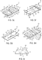
- FIGS. 3A-3I depict examples of cut patterns.
- a single cut 31 is formed in the flap 4.
- the cut 31 is shown disposed in an intermediate zone of the flap 4 between the first axial and second axial sides 12, 14 and the first lateral and second lateral sides 16, 18.
- the cut 31 is shown shaped as a linear slit having a small width relative to a longitudinal length.
- the longitudinal length of the cut 31 may be up to 40% of the length L of the flap 4.
- the cut length may be between about 1 to 5 cm, or, in one example, the cut length may be 3 cm.
- a plurality of cuts 41A, 41B, 41C is formed in the flap 4.
- the first cut 41A is shown disposed in an intermediate zone of the flap 4 between the first axial and second axial sides 12, 14 and the first lateral and second lateral sides 16, 18.
- the second cut 41B is shown disposed extending distally from the first axial side 12 to a distal location longitudinally spaced by a bridge 42Afrom the first cut 41A.
- the third cut 41C is shown disposed extending proximally from the second axial side 14 to a proximal location longitudinally spaced by a bridge 42B from the first cut 41A.
- the second and third cuts 41B, 41C are shown in an intermediate zone of the flap 4 between the first lateral and second lateral sides 16, 18.
- the cuts 41A, 41B, 41C are shown shaped as a linear slit having a small width relative to a longitudinal length.
- the longitudinal length of the cuts 41A, 41B, 41C may be the same length or may be different lengths.
- the length of the cuts may be up to 40% of the length L of the flap 4.
- the second cut pattern 40 may be expanded with additional cuts. For example, additional intermediate cuts may be formed between the first cut 41A and the second and third cuts 41B, 41C, respectively, while maintaining the distances of the bridges, which may be constant or may vary.
- the cut length may be about 1 to 5 cm and the bridge length may be about 0.5 to 1.5 cm. In one example, the cut length may be about 3 cm and the bridge length may be about 0.5 cm.
- the second cut pattern showed a slight improvement (reduced by about 5 kPa) over the first cut pattern in the amount of average expansion stress required for full flap reapposition.
- a single cut 51 is formed in the flap 4.
- the cut 51 is shown disposed in an intermediate zone of the flap 4 between the first axial and second axial sides 12, 14 and the first lateral and second lateral sides 16, 18.
- the cut 51 is shown shaped as a linear slit having a small width relative to a longitudinal length.
- the longitudinal length of the cut 51 may be 40% to 70% of the length L of the flap 4.
- the cut length may be about 5 to about 8 cm. In another example, the cut length is about 6.5 cm.
- the third cut pattern showed a substantial improvement (reduced by over 50% or about 15 kPa) over the first cut pattern in the amount of average expansion stress required for full flap reapposition. The longer length of cut in the third cut pattern may also require additional healing time.
- a plurality of cuts 61A, 61B, 61C, 62A, 62B, 62C, 63A, 63B, 63C is formed in the flap 4.
- the cuts 61A, 61B, 61C are shown forming an intermediate first row.
- the cuts 62A, 62B, 62C form an outer second row laterally or circumferentially spaced from the intermediate first row by a first spacing 64A and laterally spaced from the first lateral side 16 by a first end spacing 65A.
- the first end spacing 65A may be smaller in distance than the first spacing 64A.
- the cuts 63A, 63B, 63C form an outer third row laterally or circumferentially spaced from the intermediate first row by a second spacing 64B and laterally spaced from the second lateral side 18 by a second end spacing 65B.
- the second end spacing 65B may be smaller in distance than the second spacing 64B.
- the first and second end spacings 65A, 65B may have the same distance between the respective cuts. Alternatively, the distances of first and second end spacings 65A, 65B may vary or be different.
- the first and second spacings 64A, 64B may have the same distance between each of the respective adjacent cuts or such distances may vary between the respective adjacent cuts.
- the first cut 61A is shown disposed in an intermediate zone of the flap 4 between the first axial and second axial sides 12, 14 and the first lateral and second lateral sides 16, 18.
- the second cut 61B is shown disposed extending distally from the first axial side 12 to a distal location longitudinally spaced by a bridge 66A from the first cut 61A.
- the third cut 61C is shown disposed extending proximally from the second axial side 14 to a proximal location longitudinally spaced by a bridge 66B from the first cut 61A.
- the second and third cuts 61B, 61C are shown in an intermediate zone of the flap 4 between the first lateral and second lateral sides 16, 18.
- the first cut 62A is shown disposed in an intermediate zone of the flap 4 between the first axial and second axial sides 12, 14.
- the second cut 62B is shown disposed extending distally from the first axial side 12 to a distal location longitudinally spaced by a bridge 67A from the first cut 62A.
- the third cut 62C is shown disposed extending proximally from the second axial side 14 to a proximal location longitudinally spaced by a bridge 67B from the first cut 62A.
- the first cut 63A is shown disposed in an intermediate zone of the flap 4 between the first axial and second axial sides 12, 14.
- the second cut 63B is shown disposed extending distally from the first axial side 12 to a distal location longitudinally spaced by a bridge 68A from the first cut 63A.
- the third cut 62C is shown disposed extending proximally from the second axial side 14 to a proximal location longitudinally spaced by a bridge 68B from the first cut 63A.
- the cuts 61A, 61B, 61C, 62A, 62B, 62C, 63A, 63B, 63C are shown shaped as linear slits having a small width relative to a longitudinal length.
- the longitudinal length of the cuts 61A, 61B, 61C, 62A, 62B, 62C, 63A, 63B, 63C may be the same length or may be different lengths.
- the lengths of the cuts may be up to 40% of the length L of the flap 4.
- the bridges and cuts may be generally aligned longitudinally and laterally.
- the cut length may be about 1 to 5 cm and the bridge length is about 0.5 cm to 1.5 cm, and the circumferential spacing is about 1 to 3 cm. In one example, the cut length is about 3 cm and the bridge length is about 0.5 cm, and the circumferential spacing is about 2 cm.
- the fourth cut pattern showed a substantial improvement (reduced by over 50% or about 15 kPa) over the first cut pattern in the amount of average expansion stress required for full flap reapposition. In comparison with the third cut pattern, the fourth cut pattern showed a slight improvement in the amount of average expansion stress required for full flap reapposition.
- the peak stresses along the bridges may be higher than desirable.
- the fourth cut pattern 60 may be expanded with additional cuts.
- additional intermediate cuts may be formed between the first cuts 61A, 62A, 63A and the second and third cuts 61B, 61C, 62B, 62C, 63B, 63C, respectively, while maintaining the distances of the bridges and lateral spacings, whether constant or varying, between adjacent cuts and the lateral sides.
- a fifth cut pattern 70 is shown in FIG. 3E , including a plurality of cuts 71A, 71B, 71C, 72A, 72B, 72C, 73A, 73B, 73C, 74A, 74B, 74C, 75A, 75B, 75C is formed in the flap 4.
- the fifth cut pattern 70 may be substantially the same as the fourth cut pattern 60, with the following clarifications.
- the cuts 71A, 71B, 71C, 72A, 72B, 72C, 73A, 73B, 73C may have the same general location and configuration as the cuts 61A, 61B, 61C, 62A, 62B, 62C, 63A, 63B, 63C, and for sake of time will not described in any more detail than what has already been described in relation to the fourth cut pattern 60.
- the cuts 74A, 74B, 74C, 75A, 75B, 75C form additional intermediate rows (the intermediate second row and the intermediate third row, respectively,) which are shown disposed within the first and second spacings 64A, 64B of the previous cut pattern, which are now referred to as spacings 78A, 78B, respectively.
- the first cut 74A is shown disposed in an intermediate zone of the flap 4 between the first lateral and second lateral sides 16, 18, and in particularly in the first spacing 78A between the cuts 72A, 71A.
- the second cut 74B is shown in the first spacing 78A disposed extending distally from the first axial side 12 to a distal location longitudinally spaced by a bridge 76A from the first cut 74A.
- the third cut 74C is shown in the first spacing 78A disposed extending proximally from the second axial side 14 to a proximal location longitudinally spaced by a bridge 76B from the first cut 74A.
- the first cut 75A is shown disposed in an intermediate zone of the flap 4 between the first lateral and second lateral sides 16, 18, and in particularly in the second spacing 78B between the cuts 73A, 71A.
- the second cut 75B is shown in the second spacing 78B disposed extending distally from the first axial side 12 to a distal location longitudinally spaced by a bridge 77A from the first cut 75A.
- the third cut 74C is shown in the first spacing 64A disposed extending proximally from the second axial side 14 to a proximal location longitudinally spaced by a bridge 77B from the first cut 75A.
- the cut length may be about 1 to 5 cm and the bridge length is about 0.5 to 1.5 cm, and the circumferential spacing is about 0.5 to 1.5 cm. In one example, the cut length is about 3 cm and the bridge length is about 0.5 cm, and the circumferential spacing is about 1 cm.
- the fifth cut pattern showed a substantial improvement (reduced by over 60%) over the first cut pattern in the amount of average expansion stress required for full flap reapposition. In comparison with the fourth cut pattern, the fifth cut pattern showed a slight improvement in the amount of average expansion stress required for full flap reapposition.
- the peak stresses along the bridges may be higher than desirable.
- the next examples show the cuts in a longitudinally overlapping pattern.
- a plurality of cuts 81A, 81B, 81C, 81D, 81E is formed in the flap 4.
- the cut 81A is shown disposed in an intermediate zone of the flap 4 between the first lateral and second lateral sides 16, 18.
- the cut 81B is laterally or circumferentially spaced from the cut 81A by a first spacing 84A and laterally or circumferentially spaced from the first lateral side 16 by a first end spacing 85A
- the cut 81C is laterally spaced from the cut 81A by a second spacing 84B and laterally spaced from the second lateral side 18 by a second end spacing 85B.
- the cuts 81A, 81B, 81C may be disposed extending from one of the first and second axial sides 12, 14 (for example, shown extending proximally from the second axial side 14).
- the cuts 81D, 81E are formed at the opposite side of the cuts 81A, 81B, 81C (shown extending distally from the first axial side 12).
- the cut 81D is shown disposed within the first spacing 84A and laterally spaced from the cuts 81A, 81B and laterally spaced from the first lateral side 16 by a third end spacing 85C that is greater the first end spacing 85A.
- the cut 81E is shown disposed within the second spacing 84B and laterally spaced from the cuts 81A, 81C and laterally spaced from the second lateral side 18 by a fourth end spacing 85D that is greater the second end spacing 85B.
- the cuts 81A, 81B, 81C, 81D, 81E are shown shaped as linear slits having a small width relative to a longitudinal length.
- the longitudinal length of the cuts 81A, 81B, 81C, 81D, 81 E may be the same length or may be different lengths.
- the lengths of the cuts may be more than 50% to less than the full length L of the flap 4.
- the ends of the cuts are shown longitudinally offset to form an overlapping pattern along an intermediate region. In one example, the degree of overlapping is such that the ends of the cuts are longitudinally positioned up anywhere between the end and up to the longitudinal center of the adjacent cut.
- the sixth cut pattern 80 may be expanded with additional cuts.
- additional cuts may be formed along either side, while maintaining the distances of the bridges, which may be constant or may vary.
- the cut length may be about 4 to 8 cm and the bridge length may be about 0.5 to 1.5 cm, and the circumferential spacing may be about 1 to 3 cm between adjacent cuts and a length of 0.5 to 1.5 cm between cuts along intermediate region.
- the cut length is about 6 cm and the bridge length is about 0.5 cm, and the circumferential spacing is about 2 cm between adjacent cuts and the length of 1 cm between cuts along intermediate region.
- the sixth cut pattern showed a substantial improvement (reduced by over 80%) over the first cut pattern in the amount of average expansion stress required for full flap reapposition.
- the sixth cut pattern showed a slight improvement in the amount of average expansion stress required for full flap reapposition.
- the peak stresses along the bridges may be higher than desirable.
- the sixth cut pattern showed the most improvement over the other disclosed cut patterns, the longer length of cuts in the sixth cut pattern may also require additional healing time.
- the cuts in any of the cut patterns disclosed may have a variety of shapes and sizes.
- the cuts may have an undulated, zigzag, or stepped shape or may have other shapes, regular or irregular.
- a plurality of cuts 91A, 91B, 92A, 92B having an undulated, zigzag (shown), or stepped shape is formed in the flap 4.
- the cuts 91A, 91B are shown forming an intermediate first row.
- the cuts 92A, 92B form an intermediate second row laterally spaced from the intermediate first row by a first spacing 94 and laterally spaced from the first lateral side 16 by a first end spacing 95.
- the first end spacing 95 may have the same distance between the respective cuts. Alternatively, the distances of the first spacing 95 may vary or be different.
- the first spacing 94 may have the same distance between each of the respective adjacent cuts or such distances may vary between the respective adjacent cuts.
- the first cut 91A is shown disposed in an intermediate zone of the flap 4 between the first axial and second axial sides 12, 14 and the first lateral and second lateral sides 16, 18.
- the second cut 91B is shown disposed extending proximally from the second axial side 14 to a proximal location longitudinally spaced by a bridge 96A from the first cut 91A.
- the first cut 92A is shown disposed extending distally from the first axial side 12 to a distal location longitudinally spaced by a bridge 96B from the second cut 92B.
- the second cut 92B is shown disposed extending proximally from the second axial side 14 to a proximal location longitudinally spaced by the bridge 96B from the first cut 92A.
- the cuts 91A, 91B, 92A, 92B are shown shaped as slits having a small width relative to a longitudinal length.
- the longitudinal length of the cuts 91A, 91B, 92A, 92B may be the same length or may be different lengths.
- the lengths of the cuts may be up to 50% of the length L of the flap 4.
- the seventh cut pattern 90 may be expanded with additional cuts. For example, additional intermediate cuts may be formed between the cuts 91A, 92A and the cuts 91B, 92B, respectively, while maintaining the distances of the bridges and lateral spacings, whether constant or varying, between adjacent cuts and the lateral sides.
- the seventh cut pattern showed a substantial improvement (reduced by over 50%) over the first cut pattern in the amount of average expansion stress required for full flap reapposition.
- a plurality of cuts 101A, 101B, 101C, 102A, 102B, 103A, 103B is formed in the flap 4 in a longitudinally overlapping pattern.
- the cuts 101A, 101B, 101C are shown forming an intermediate first row.
- the cuts 102A, 102B form an outer second row laterally or circumferentially spaced from the intermediate first row by a first spacing 104A and laterally spaced from the first lateral side 16 by a first end spacing 105A.
- the first end spacing 105A may be smaller in distance than the first spacing 104A.
- the cuts 103A, 103B form an outer third row laterally or circumferentially spaced from the intermediate first row by a second spacing 104B and laterally spaced from the second lateral side 18 by a second end spacing 105B.
- the second end spacing 105B may be smaller in distance than the second spacing 104B.
- the first and second end spacings 105A, 105B may have the same distance between the respective cuts. Alternatively, the distances of first and second end spacings 105A, 105B may vary or be different.
- the first and second spacings 104A, 104B may have the same distance between each of the respective adjacent cuts or such distances may vary between the respective adjacent cuts.
- the first cut 101A is shown disposed in an intermediate zone of the flap 4 between the first axial and second axial sides 12, 14 and the first lateral and second lateral sides 16, 18.
- the second cut 101B is shown disposed extending distally from the first axial side 12 to a distal location longitudinally spaced by a bridge 106A from the first cut 101A.
- the third cut 101C is shown disposed extending proximally from the second axial side 14 to a proximal location longitudinally spaced by a bridge 106B from the first cut 101A.
- the second and third cuts 101B, 101C are shown in an intermediate zone of the flap 4 between the first lateral and second lateral sides 16, 18.
- first and second cuts 102A, 102B are shown disposed in an intermediate zone of the flap 4 between the first axial and second lateral sides 16, 18.
- the first cut 102A is shown disposed distal to the first axial side 12 by a material spacer 108A.
- the second cut 102B is shown disposed proximal to the second axial side 14 by a material spacer 108B.
- the first cut 102A is shown longitudinally spaced by a bridge 107A from the second cut 102B.
- the first and second cuts 103A, 103B are shown disposed in an intermediate zone of the flap 4 between the first axial and second lateral sides 16, 18.
- the first cut 103A is shown disposed distal to the first axial side 12 by a material spacer 109A.
- the second cut 103B is shown disposed proximal to the second axial side 14 by a material spacer 109B.
- the first cut 103A is shown longitudinally spaced by a bridge 107B from the second cut 103B.
- the cuts 101A, 101B, 101C, 102A, 102B, 103A, 103B are shown shaped as slits having a small width relative to a longitudinal length.
- the longitudinal length of the cuts 101A, 101B, 101C, 102A, 102B, 103A, 103B may be the same length or may be different lengths.
- the lengths of the cuts may be up to 40% of the length L of the flap 4.
- the cut length may be about 1 to 5 cm, the bridge length is about 0.5 to 1.5 cm, the spacer length is about 1.5 to 2.5 cm, and the circumferential spacing is about 0.5 to 1.5 cm.
- the cut length is about 3 cm
- the bridge length is about 0.5 cm
- the spacer length is about 1.8 cm
- the circumferential spacing is about 1 cm.
- the eighth cut pattern showed a substantial improvement (reduced by over 40%) over the first cut pattern in the amount of average expansion stress required for full flap reapposition. In comparison with the other cut patterns, the eighth cut pattern showed the most improved results when also considering healing time and peak stress loads.
- the eighth cut pattern 100 may be modified to include only two rows of cuts to form a ninth pattern 100A shown in FIG. 3I .
- the cuts 101A, 101B, 101C may form a first row not centrally located but further circumferentially offset, and the cuts 102A, 102B circumferentially spaced from the first row similar to the two row cut pattern in FIG. 3G .
- FIG. 4 depicts an example pattern 110 of a longitudinally overlapping arrangement, where a cut overlaps a portion of an adjacent cut.
- the pattern 110 may include one or more of the cuts shown.
- the first cut 111A and the second cut 111B are longitudinally spaced from one another by the bridge 112.
- a longitudinal center 113 of the bridge 112 defined between longitudinally adjacent cuts 111A, 111B is disposed in alignment with a longitudinal center 114 of the cut 115A of cuts 115A, 115B that are laterally or circumferentially adjacent.
- Each of the cuts, for example cut 111A includes a first end 116 associated with the proximal end and a second end 117 associated with the distal end.
- a longitudinal center 118 is defined at the midpoint (shown by the line) between the first end 116 and the second end 117.
- the first end 116A of the cut 115A is shown overlapping the second end 117 of the cut 111A, and the second end 117 of the cut 111A is shown overlapping the first end 116A of the cut 115A.
- the first end 116A of the cut 115A is positioned between the second end 117 of the cut 111A and the longitudinal center 118 of the cut 111A.
- the second end 117 of the cut 111A is positioned between the first end 116A of the cut 115A and the longitudinal center 114 of the cut 115A.
- the overlapping pattern of the cuts may be arranged to provide each circumferential segment of the flap that is discontinuous, that is, a portion of at least one of the cuts is present within each circumferential segment along substantially the entire (for example, 50% to 100% of) flap length.
- FIG. 4 depicts three adjacent circumferential segments adjacent to one another along the flap, with the second circumferential segment 120 disposed between the first and third circumferential segments 121, 122.
- the second circumferential segment 120 may include portions of non-overlapping adjacent cuts, and the first and third segments 121, 122 may include portions of the overlapping adjacent cuts.
- the cut density of the circumferential segment of the flap is defined as the number of cuts per an area of circumferential segment of the flap.
- the second circumferential segment 120 may include a lower or smaller cut density than the cut density of at least one of the first and third segments 121, 122.
- the overlapping pattern of the cuts may be arranged to provide each circumferential segment of the flap that is discontinuous or interrupted by at least one cut, that is, a portion of at least one of the cuts is present within each circumferential segment along the entire flap length.
- the term "cut” may be used herein to describe partial tissue cuts where a partial portion of tissue is cut into and/or partially removed and/or to describe full tissue cuts where tissue is cut into or removed fully to define a through opening in the body tissue.
- the cuts may be referred to as "slits" or “openings” and can have a variety of shapes, such as for example, rectangular, circular, elliptical, star-shaped.
- the shape of the cuts may be linear or nonlinear, such as having an undulated, zigzag, or stepped shape.
- the shape of the cuts may be derivatives of the shapes disclosed or may be irregular due to the nature of the tissue, cutting device orientation, and other factors.
- FIG. 5 is a partial cross-sectional view of one example of any one of the disclosed cuts.
- the cut 130 includes a distal end 132 and a proximal end 134.
- An intermediate through opening 136 is bounded by a distal partial cut 137 extending from the distal end 132, and a proximal partial cut 138 extending from the proximal end 134 such that the cross-sectional shape of the cut varies.
- FIG. 6 is a partial cross-sectional view of another example of any one of the disclosed cuts.
- a partial cut 140 is formed in a manner that there is not a through opening.
- a reduced wall 141 is formed between the distal end 142 and the proximal end 144.
- Any one of the patterns may include the same type of cuts or different cuts that vary along the body tissue.
- tissue cutting devices may be utilized for in-situ or in-vivo cutting operations.
- an electrosurgical tissue cutting system using monopolar, bipolar, and/or sesquipolar RF energy generation a laser system, an ultrasound or ultrasonic system, an electrical voltage resistive heating system, a mechanical blade system or scalpel, a microwave system, and a cryogenic fluid system.
- FIG. 7 depicts one example of a tissue cutting system that may be used for medical treatment.
- a tissue cutting system 210 is more fully described in U.S. Provisional Application S/N 62/459,344 , entitled “Cutting System and Method for Tissue Cutting for Medical Treatment," filed on February 16, 2017, which is hereby incorporated by reference in its entirety.
- the electrosurgical tissue cutting system 210 illustrates a sequipolar arrangement, suitable modifications to the system may convert the devices to a bipolar or monopolar arrangement, as understood by one of ordinary skill in the art.
- the electrosurgical tissue cutting system 210 may include a power supply (not shown) in electrical communication with a first device 230 and a second device 250.
- the first device 230 may be electrically connected via a conductor to one pole of a radio frequency (RF) generator RFG housed in the power supply.
- the second device 250 may be electrically connected to the other pole of the RF generator of the power supply.
- the first device 230 may include a first outer sheath 232 with a tubular body extending between a proximal end and a distal end and disposed about a first device longitudinal axis.
- the first outer sheath 232 is movable in the distal and proximal directions for selective deployment of a first cutting device 238 which may be housed within a longitudinal sheath lumen of the first outer sheath 232.
- the first outer sheath 232 may also include a side branch or other port for receiving the first electrical conductor.
- the first cutting device 238 may have one or more conductive probes 270 having an energizable tip 272.
- the conductive probe 270 includes an elongated body of an electrical conductive material.
- An insulating jacket 276 may be disposed about the probe body, leaving the energizable tip 272 exposed.
- the probe body is shown having a curvilinear shaped portion proximate its proximal end, where the energizable tip 272 is located.
- the energizable tip 272 includes an engagement region disposed at a curved bend (as shown), at an angular bend or corner, or planar region.
- the engagement region of the energizable tip 272 defines a tip surface area of electrical conductive material.
- the energizable tip 272 may also be disposed along a linear portion or other geometric shape portions to define a desired cut shape.
- the extension length of each of the conductive probes may be about the same length or longitudinally offset to create one of the disclosed cut patterns.
- Connector members (not shown) may be coupled in between adjacent conductive probes 270 to fix the circumferential spacing between the conductive probes 270 when separated in the deployed configuration.
- the second device 250 may comprise a second outer sheath 252 with a tubular body extending between a proximal end and a distal end disposed about a second device longitudinal axis.
- the second outer sheath 252 is movable in the distal and proximal directions for selective deployment of a second cutting device 258, which may be housed within a longitudinal sheath lumen of the second outer sheath 252.
- the second outer sheath 252 may also include a side branch in communication with the sheath lumen of the second outer sheath 252 for allowing the passage of the second electrical conductor.
- the second electrical conductor extends farther within the sheath lumen for electrical connection to the second cutting device 258.
- the second cutting device 258 is shown having an expandable body 300 that includes an outer surface 302 with an electrical conductive material 304.
- the expandable body 300 is movable between a radially contracted configuration and a radially expanded configuration.
- the amount of the electrical conductive material 304 defines an outer surface area when the second cutting device 258 is in its radially expanded configuration.
- the outer surface area of is at least greater than the tip surface area of the energizable tip. In one example, the ratio between the outer surface area of the expandable body 300 to the tip surface area defines a sesquipolar electrode arrangement.
- the expandable body 300 may be defined by a metal frame comprised of at least a proximal tapered section and a body or barrel section distal to the proximal tapered section.
- the metal frame of the body section may comprise of a wire mesh or woven structure, strut framework, or other stent frame structure, such as a cannula cut stent, that can be radially compressible and expandable.
- the body section is shown extending axially at a uniform cross-sectional profile or cylindrical profile, although the body section may have an outward or inward curvature or may taper along the axis in the proximal direction to have an increasingly larger or smaller cross-sectional area profile along different regions of the body section for better conformity within the body vessel.
- the expandable body 300 may include an inflatable balloon device.
- an inner cannula of the balloon device is surrounded by a balloon membrane sealably attached to the inner cannula at proximal and distal attachment locations.
- the inner cannula is configured to receive inflation fluid.
- the balloon membrane may be shaped to have a proximal tapered section, a working body section, and a distal tapered section.
- the inflation fluid may be an electrically nonconductive to inhibit electrical energy flow into the first device outside the conductive surface.
- the working body section may define a cylindrical shape as shown or may be tapered for better conformity with the body vessel.
- the second outer sheath may be included for selectively sliding over the balloon membrane when in the deflated configuration.
- the first device 230 and the second device 250 of the electrosurgical tissue cutting system 210 work in coordination for cutting tissue based on the electrical power or current delivered by the power supply to a contacted, or target, portion of tissue within a patient.
- the tissue primarily contemplated is an aorta dissection flap; however, other applications of the system 210 may include small blood vessels in need of cauterization, tumor, or other undesirable tissue to be removed from the patient.
- the first device 230 and the second device 250 may be configured to be manipulated by a human operator and/or a robot.
- the RF generator RFG of the power supply may include a RF energy generator such that electrical current flows to the energizable tip 272 of the first cutting device 238 of the first device 230 (or active electrode), and the expandable body 300 of the second cutting device 258 of the second device 250 (or return electrode), which are cooperatively operative to form the cut.
- the energizable tip 272 and the expandable body 300 are disposed across from each other on the obverse sides of the tissue to be cut or perforated in engagement with the tissue sides.
- the RF energy generator may be suitable for sesquipolar or other configurations. Electric current may be oscillated between the energizable tip 272 and the expandable body 300.
- the energizable tips 272 may be sequentially energized during power. For example, the energizable tips 272 may remain deployed and axially move along the tissue, while the tips 272 are sequentially phased on and off. In this arrangement, the cuts formed in the tissue are formed one at a time.
- the selective energization may be controlled by the control switch or there may be a switching module (hardware or software) included with the power supply.
- the energizable tips may be energized at the same time during oscillation to form more than one cut at a time.
- the smaller tip surface area of the energizable tip 272 and the larger cross-sectional area of the expandable body 300 are operable together to form a cut into the tissue by tissue vaporization and RF arc generation, as appreciated by those of skill in the art.
- the RF arc at the tissue is generated, with the energizable tip 272 as the active electrode and the expandable body as the return probe, which directs energy at the tissue interface.
- the RF arc is most intense at the engagement region of the energizable tip 272, which may move toward the expandable body with pressure.
- the cutting current may be constant, intermittent or a combination of both. In one example, the cutting current is constant for cutting without coagulation.
- the electrical conductive material described above for any of the components may include platinum, gold, copper and/or silver, or alloys thereof.
- the conductive probe may be made of a shape memory alloy such as Nitinol. Other conductive materials may be used without departing from the scope of this disclosure.
- Portions of the first device and/or the second device may be covered in electrical insulation or may be otherwise insulated such that the first and second cutting devices may deliver electrical energy from the power supply to the contacted tissue.
- the electrical insulation may be any appropriate electrically insulating material including, but not limited to, plastic, rubber, vinyl, epoxy, parylene, or ceramic and may enable the operator to grasp the devices as well as protect the patient's body.
- FIGS. 8-9 illustrate another example of a tissue cutting system 400.
- the tissue cutting system 400 includes a pair of cutting devices 402, 404 cooperatively operable to form a cut into a tissue wall or flap.
- the first device 402 includes at least one blade 408 (two shown) coupled to a device body 410.
- the first device 402 includes a single blade in either of the positions shown or other positions such as centrally located.
- the blade or blades 408 may be oriented, arranged, and sized to define partially or fully one of the disclosed cut patterns listed above.
- the blade(s) may selectively or permanently protrude away from a confronting surface 412 of the device body that faces the second device and the tissue during operation.
- the blade may comprise a metal, such as stainless steel, having a sharpened edge suitable for cutting body tissue, such as the dissection flap or intima layer of the wall.
- the second device 404 includes at least one blade recess 420 (two shown) formed in a confronting surface 422 of a device body 430.
- the blade recess or recesses 420 may be complementarily arranged in a mirror image pattern of the blades 408 of the first device 402. In the instance of a single blade device, a single recess may be present and arranged accordingly.
- the blade recesses(s) are sized and shaped to receive the blades 408.
- the tissue cutting system 400 includes a non-cutting configuration (shown in FIG. 8 ) where the devices do not sliceably engage the tissue and allow for relative movement between the devices, and a cutting configuration (shown in FIG. 9 ) where the devices form cuts in the tissue by the devices movement against one another.
- each body may include a blade and a cooperatively placed recess.
- the bodies 410, 430 made of biocompatible materials, as understood in the art, may house one or more magnetic devices, that is, magnets or electromagnets, used for aligning the blades and blade recesses in the longitudinal and circumferential directions during the cutting operation.
- the body 410 includes four magnetic devices 435A, 435B, 435C, 435D having a complementary polarity for coupling with the four magnetic devices 436A, 436B, 436C, 436D of the body 430.
- pairs of magnetic devices (435A, 436B), (435B, 436A), (435C, 436D), and (435D, 435C) have a complementary polarity for coupling.
- Adjacent magnetic devices such as devices 435A, 435B, may have opposite polarity such that magnetic devices 436A, 436B are only attracted to the correct magnetic device.
- the magnetic devices 435A, 435B, 435C, 435D, 436A, 436B, 436C, 436D of at least one of the bodies are selectively magnetic to control the coupling and cutting operation.
- the magnetic devices are coupled to electrical energy via internal wiring or circuits that is coupled to a power conductor, which is shown extending through a cannula 439 to a power supply external to the patient.
- the selective energization may be controlled by a control switch or there may be switching module (hardware or software) included with the power supply.
- the magnets may be rare earth magnets or electromagnets having sufficient magnetic power and strength to attract and align another source of magnetic attraction such as the magnets of the other device in-vivo.
- the magnets may include the neodymium-iron-boron compositions and cobalt-samarium compositions. Any number of individual magnets (e.g., zero, one, two, three, four, five, six, seven, or eight or more, etc.) may be provided. These magnets may located inside, outside, or combination thereof of the body of the devices, and may be positioned anywhere along the length of the bodies. Each magnet may be fixed in or on the bodies by any suitable method, for example, embedded in, adhered to or friction fit within the bodies.
- the magnets may have alternating polarity (for example, each magnet may have the opposite polarity as any adjacent magnets), the same polarity, or combinations thereof.
- the electromagnets may be activated, for example, selectively activated or may be activated one at a time to help ensure a certain alignment orientation with respect to the magnets to the other devices, for example, the more proximal magnets may be activated prior to activating the more distal magnets.
- the magnets may be activated in sequence, or alternatively, two or more magnets may be activated simultaneously to promote secure attachment to the other magnets.
- the bodies 410, 430 may have imageable indicators 440 coupled or otherwise formed with the bodies, which are visible under fluoroscopic guidance or some other method of imaging.
- the imageable indicators 440 configured in a manner that permits identification of particular areas that correspond to a feature of particular importance on the device.
- the imageable indicator 440 may include an ultrasonically reflective surface, such as providing a series of indentations in the surface of the device that are configured to reflect sound waves and allow for ultrasound imaging of that particular region. As with the radiographically imageable structure, the ultrasonically reflective surface would be located at selected points along the device that correspond with a particular critical feature or structure thereof.
- the imageable indicators 440 may include radiopaque markers at selected locations that would indicate if the devices become tilted at or following deployment.
- the devices 402, 404 may include a repel mechanism 445 to aid in separating the devices after forming a cut.
- the repel mechanism 445 may take the form of a leaf spring 446 having an end 447 attached to the major or confronting surface 422 of one of the bodies, such as the body 430, and an opposite end 449 spaced and biased from the confronting surface 422.
- the repel mechanism 445 may be provided on both of the bodies.
- the magnetic force generated by the device magnets is greater than the repelling force of the repel mechanism 445, which allows the devices 402, 404 to couple and form the cuts.
- the repel mechanism 445 is operable to push against the corresponding opposite body to move the devices away from each other.
- the blades 408 may be retractable.
- the blades 408 may be spring biased in a manner such that when activated the blades protrude out, and when deactivated the blades 408 retract within the body.
- the bodies 410, 430 may include a shield or a shroud (not shown) around the blade 408.
- the shroud may form a boundary around the blade.
- the shroud may be spring biased in a manner such that when activated the shroud may protrude out, and when deactivated the shroud retracts within the body.
- the device bodies 410, 430 may be configured for tracking along a guidewire.
- the bodies may include a longitudinal bore for allowing the body to track along the guidewire.
- the longitudinal bore may be in fluid communication to the lumen within the cannula 439.
- the cutting system includes a first and second cutting devices. At least one of the cutting devices includes at least one blade, and the other cutting device includes a blade recess configured to receive the blade.
- Each of the first and second cutting devices may include magnetic devices for selective coupling to one another for completing a cutting operation. At least one of the first and second cutting devices may include a repel mechanism operable to move the devices away from each other.
- the first and second cutting devices may be cooperatively operative to form the cut.
- the cutting devices may include an cannula extending to a cutting device body and may include a guidewire lumen extending through the body and cannula.
- FIGS. 8-9 depict aspects of the operation of the device.
- One of the devices 402, 404 may be inserted and positioned along one side of the body tissue, such as into the true lumen, and the other of the devices may be inserted along the opposite side of the body tissue, such as into the false lumen, similar to the system in FIG. 7 , such that the body tissue or flap is disposed between the devices 402, 404.
- the devices 402, 404 may be positioned along the desired site of treatment.
- the magnets of one of the devices are magnetically attracted to the magnets of the other device to move from the non-cutting configuration to the cutting configuration.
- the shape of the blade and blade recess and the insertion of the blade into the blade recess are cooperatively operative to form a cut or cuts.
- the magnets are electromagnets
- the electromagnets may be electrically activated in a manner known in the art for the cutting operation and deactivated to allow the devices to be moved and repositioned for another cutting operation.
- At least the cutting device introduced into the true lumen may be pressed against the dissection flap by an expandable device discussed above.
- the other cutting device may be directed to the dissection wall within the false lumen as described in connection with Fig. 7 by a curvilinear shaped portion.
- FIG. 12 A flow diagram describing an example method 500 is provided in FIG. 12 .
- other methods of cutting a tissue such as but not limited to, methods of treating blood vessels in need of cauterization or fistulas, or methods of removing tumors or other undesirable tissue.
- the order of the steps described below may be altered or adjusted, and some of the steps may be omitted or combined with other steps.
- the one or more cutting devices or systems may be inserted and positioned within at least one of a true lumen and a false lumen and moved to a position along a dissection flap where treatment is desired.
- a cut is formed in a body tissue with any one of the disclosed cutting devices or systems.
- a cut may be formed in a dissection flap.
- the cut may be formed in-situ or in-vivo into the intima flap in order to reduce the tissue's resistance to displacement or to alleviate the circumferential strength of the intima flap.
- any one of the disclosed cutting devices or systems is inserted within the body vessel.
- the cutting system may include a single cutting device or more than one cutting devices that are cooperatively operative to form the cut.
- Guidewires may be introduced from a femoral artery or other known artery method into an aorta or the body vessel. For example, with reference to FIG.
- a first guidewire 499 may be located along the first side of the body tissue, for example, from the main or true lumen of aorta and into the false lumen 6, and a second guidewire 501 may be placed along the opposite side of the body tissue, for example, into the true lumen 7.
- the first guidewire may be extended through a flap opening that provides access into the false lumen.
- Any one of the disclosed cutting devices may be inserted over the second guidewire for tracking along the first body tissue side, for example, into the true lumen, and the other of the cutting devices may be inserted over the first guidewire and tracked to a position along the second body tissue side, for example, into the false lumen.
- the cutting devices are located against the obverse sides of the tissue, such as the dissection flap.
- the cutting devices are appropriately positioned along the treatment site. For example, the cutting device may be positioned initially along the proximal end such that the devices may be retracted distally to form additional cuts along the body tissue.
- any one of the disclosed cutting devices may be activated to form a cut or cuts (shown as cut 503 in FIG. 7 ), as appreciated by one of skill in the art.
- Activation of the cutting devices may take various forms, as previously described, depending on the kind of the cutting device(s) used, for example, an electrosurgical tissue cutting system using monopolar, bipolar, and/or sesquipolar RF energy generation, a laser system, an ultrasound or ultrasonic system, an electrical voltage resistive heating system, a mechanical blade system or scalpel, a microwave system, and a cryogenic fluid system.
- activation may take the form of providing selective electrical power or current from the power supply to (thereby energizing) the first and second cutting devices, as described previously.
- electromagnets may be activated in a manner known in the art for the cutting devices with a blade to press down against each other and form the cuts.
- one or more of cuts 503 may be formed at step 502, which may comprise a single operation forming a single cut or plurality of cuts or subsequent operation to forming additional single or plurality of cuts with any one of the disclosed cutting devices.
- the cutting devices may be configured to perform multiple cuts during a single cutting action.
- the cutting devices may be moved relative to one another along the respective body tissue sides, for example, within the respective true lumen and false lumen.
- Subsequent activations of the cutting devices may be performed to form the additional cuts, for example, in one of the cut patterns disclosed herein. More than one cut pattern disclosed herein may be formed together to form a new pattern.
- a second cut may be formed in the dissection flap with the cutting devices and longitudinally offset from the first cut.
- a third cut may be formed in the dissection flap with the cutting devices, and circumferentially offset from the first cut and the second cut.
- the third cut may be circumferentially offset from and overlapping the first cut and the second cut.
- the second cut in the dissection flap formed with the cutting devices is circumferentially offset from the first cut, and the third cut is longitudinally offset from the first or second cuts.
- the cuts and cut patterns in the tissue may change the deformation mechanism of the flap from strain of the flap into bending of the tissue between the cuts. As a result of the deformation mechanism change, the reapposition of a cut or fenestrated flap may be less dependent on the aortic pressure or body vessel size. To this end, similar patterns may be used in any size body vessel.
- the expansion pressure may be provided by the expandable device 10 inserted within the body vessel 1 and permitted to radially expand, as shown in FIG. 2 and FIGS. 13-14 .
- the expandable device 10 may be sized accordingly to provide suitable expansion pressure in addition to the aortic pressure that is transmitted to the flap.
- the average stress and peak stress during full reapposition have been found to be improved by the cut or fenestrated flap.
- better stress distribution along the longitudinal length has been found in cut patterns with some degree of overlapping cuts along the entire flap length.
- each circumferential segment of the flap is to some degree discontinuous or interrupted by at least one cut. Circumferential segments without any cuts may provide regions of the flap, such as the bridges, with increased peak stresses that may cause unintended circumferential tearing during full reapposition step.
- Healing capability and/or time of the dissection flap may also be a factor with higher density of cuts or longer cut lengths impacting this factor.
- the expandable device 10 is inserted and positioned into the body vessel 1 along the first body tissue side of the flap 4 where the cuts are formed, such as within the true lumen 7, as shown in FIG. 13 .
- other medical treatment devices such as but not limited to, expandable stents, expandable stent grafts, or inflatable balloons, can be inserted in the true lumen of the body vessel. These radially expandable devices may be located in the true lumen of the body vessel along the cut zone as the treatment site.
- step 506 the expandable device 10 is radially expanded to reappose the dissection flap 4 against a wall 5 of the body vessel 1 to close the false lumen 6.
- FIG. 14 shows the process to full re-apposition.
- the cross-sectional area of the cuts 503 may become more fully open or expand when the flap is reapposed.
- This reapposition step may allow thrombosing of the false lumen and promote aortic remodeling to improve long-term outcomes of acute aortic dissections and maintaining patency of the true lumen to re-establish the original flow lumen of the body vessel, such as the aorta, and to facilitate healing of the vessel.
- the fenestrated flap may also allow for more blood to be squeezed out of the false lumen, thereby avoid the pooling of blood within the false lumen.
Landscapes
- Health & Medical Sciences (AREA)
- Life Sciences & Earth Sciences (AREA)
- Surgery (AREA)
- Engineering & Computer Science (AREA)
- Biomedical Technology (AREA)
- General Health & Medical Sciences (AREA)
- Veterinary Medicine (AREA)
- Heart & Thoracic Surgery (AREA)
- Public Health (AREA)
- Animal Behavior & Ethology (AREA)
- Medical Informatics (AREA)
- Nuclear Medicine, Radiotherapy & Molecular Imaging (AREA)
- Molecular Biology (AREA)
- Cardiology (AREA)
- Orthopedic Medicine & Surgery (AREA)
- Physics & Mathematics (AREA)
- Plasma & Fusion (AREA)
- Otolaryngology (AREA)
- Vascular Medicine (AREA)
- Transplantation (AREA)
- Oral & Maxillofacial Surgery (AREA)
- Surgical Instruments (AREA)
Applications Claiming Priority (2)
| Application Number | Priority Date | Filing Date | Title |
|---|---|---|---|
| US201762470680P | 2017-03-13 | 2017-03-13 | |
| EP18275021.6A EP3375390A1 (fr) | 2017-03-13 | 2018-02-15 | Système de coupe pour traitement médical |
Related Parent Applications (1)
| Application Number | Title | Priority Date | Filing Date |
|---|---|---|---|
| EP18275021.6A Division EP3375390A1 (fr) | 2017-03-13 | 2018-02-15 | Système de coupe pour traitement médical |
Publications (1)
| Publication Number | Publication Date |
|---|---|
| EP3785647A1 true EP3785647A1 (fr) | 2021-03-03 |
Family
ID=61231197
Family Applications (2)
| Application Number | Title | Priority Date | Filing Date |
|---|---|---|---|
| EP18275021.6A Withdrawn EP3375390A1 (fr) | 2017-03-13 | 2018-02-15 | Système de coupe pour traitement médical |
| EP20199937.2A Pending EP3785647A1 (fr) | 2017-03-13 | 2018-02-15 | Système de coupe pour traitement médical |
Family Applications Before (1)
| Application Number | Title | Priority Date | Filing Date |
|---|---|---|---|
| EP18275021.6A Withdrawn EP3375390A1 (fr) | 2017-03-13 | 2018-02-15 | Système de coupe pour traitement médical |
Country Status (2)
| Country | Link |
|---|---|
| US (2) | US11033294B2 (fr) |
| EP (2) | EP3375390A1 (fr) |
Families Citing this family (2)
| Publication number | Priority date | Publication date | Assignee | Title |
|---|---|---|---|---|
| US11033294B2 (en) * | 2017-03-13 | 2021-06-15 | Cook Medical Technologies Llc | Method of treatment for aortic dissection |
| AU2020242051A1 (en) | 2019-03-20 | 2021-11-04 | inQB8 Medical Technologies, LLC | Aortic dissection implant |
Citations (4)
| Publication number | Priority date | Publication date | Assignee | Title |
|---|---|---|---|---|
| WO1997012555A2 (fr) * | 1995-10-03 | 1997-04-10 | Cedars-Sinai Medical Center | Dispositifs de realisation d'anastomoses vasculaires |
| WO2012068273A1 (fr) * | 2010-11-16 | 2012-05-24 | Tva Medical, Inc. | Dispositifs et procédés de formation d'une fistule |
| DE102012203783A1 (de) * | 2012-03-12 | 2013-03-28 | Siemens Aktiengesellschaft | Medizinisches Kathetersystem |
| WO2015108984A1 (fr) * | 2014-01-14 | 2015-07-23 | Volcano Corporation | Ensemble cathéter pour création de site d'accès vasculaire |
Family Cites Families (38)
| Publication number | Priority date | Publication date | Assignee | Title |
|---|---|---|---|---|
| US4043342A (en) | 1974-08-28 | 1977-08-23 | Valleylab, Inc. | Electrosurgical devices having sesquipolar electrode structures incorporated therein |
| US4791843A (en) | 1987-11-02 | 1988-12-20 | Mobil Oil Corporation | Bullet punch |
| US6001093A (en) | 1993-10-15 | 1999-12-14 | Ep Technologies, Inc. | Systems and methods for creating long, thin lesions in body tissue |
| US5683384A (en) | 1993-11-08 | 1997-11-04 | Zomed | Multiple antenna ablation apparatus |
| US5449355A (en) | 1993-11-24 | 1995-09-12 | Valleylab Inc. | Retrograde tissue splitter and method |
| US5702412A (en) | 1995-10-03 | 1997-12-30 | Cedars-Sinai Medical Center | Method and devices for performing vascular anastomosis |
| EP1317908B1 (fr) | 1995-10-13 | 2011-07-06 | Medtronic Vascular, Inc. | Dispositif et système permettant une intervention interstitielle transvasculaire |
| US5830224A (en) | 1996-03-15 | 1998-11-03 | Beth Israel Deaconess Medical Center | Catheter apparatus and methodology for generating a fistula on-demand between closely associated blood vessels at a pre-chosen anatomic site in-vivo |
| US9023031B2 (en) | 1997-08-13 | 2015-05-05 | Verathon Inc. | Noninvasive devices, methods, and systems for modifying tissues |
| US6238392B1 (en) | 1999-06-29 | 2001-05-29 | Ethicon Endo-Surgery, Inc. | Bipolar electrosurgical instrument including a plurality of balloon electrodes |
| US20080091264A1 (en) | 2002-11-26 | 2008-04-17 | Ample Medical, Inc. | Devices, systems, and methods for reshaping a heart valve annulus, including the use of magnetic tools |
| US20090112303A1 (en) * | 2001-11-28 | 2009-04-30 | Lee Bolduc | Devices, systems, and methods for endovascular staple and/or prosthesis delivery and implantation |
| US7493154B2 (en) | 2002-10-23 | 2009-02-17 | Medtronic, Inc. | Methods and apparatus for locating body vessels and occlusions in body vessels |
| DE60326000D1 (de) | 2002-12-04 | 2009-03-12 | Cook Inc | Verfahren und vorrichtung zur behandlung bei aortasektion |
| US8021359B2 (en) | 2003-02-13 | 2011-09-20 | Coaptus Medical Corporation | Transseptal closure of a patent foramen ovale and other cardiac defects |
| US20050187545A1 (en) | 2004-02-20 | 2005-08-25 | Hooven Michael D. | Magnetic catheter ablation device and method |
| US8142427B2 (en) | 2004-04-23 | 2012-03-27 | Boston Scientific Scimed, Inc. | Invasive ablation probe with non-coring distal tip |
| US8845635B2 (en) | 2005-01-18 | 2014-09-30 | S.D.M.H. Pty. Ltd. | Device and method for thermal ablation of biological tissue using spherical ablation patterns |
| EP1793766B3 (fr) | 2004-09-28 | 2012-07-04 | William A. Cook Australia Pty. Ltd. | Dispositif permettant de traiter les anevrismes dissequants |
| US8696662B2 (en) | 2005-05-12 | 2014-04-15 | Aesculap Ag | Electrocautery method and apparatus |
| EP1955680A1 (fr) | 2005-11-14 | 2008-08-13 | JMS Co., Ltd. | Instrument de dilatation de canal sanguin et de traitement de la dissection aortique |
| US8062321B2 (en) | 2006-01-25 | 2011-11-22 | Pq Bypass, Inc. | Catheter system for connecting adjacent blood vessels |
| WO2007128064A1 (fr) | 2006-05-08 | 2007-11-15 | Cathrx Ltd | Introduction d'un mécanisme conférant une forme |
| WO2008057720A1 (fr) | 2006-11-08 | 2008-05-15 | Cardiac Pacemakers, Inc. | Implant permettant de fixer un capteur dans un vaisseau |
| JPWO2008081613A1 (ja) | 2006-12-28 | 2010-06-17 | 株式会社▲高▼橋型精 | 抜き型 |
| WO2009046441A1 (fr) | 2007-10-05 | 2009-04-09 | Coaptus Medical Corporation | Systèmes et procédés pour procédures cardiaques transeptales comprenant des câbles de guidage séparables, des éléments de pénétration de tissus, des éléments de scellage de tissus et des dispositifs de compression de tissus |
| EP2317952A1 (fr) | 2008-07-17 | 2011-05-11 | Maestroheart SA | Dispositif médical destiné à l'ablation de tissus |
| US8491613B2 (en) | 2009-11-17 | 2013-07-23 | W. L. Gore & Associates, Inc. | Aortic dissection septal cutting tool |
| US8556921B2 (en) | 2009-11-17 | 2013-10-15 | W. L. Gore & Associates, Inc. | Method of using an aortic dissection septal cutting tool |
| US9393100B2 (en) | 2010-11-17 | 2016-07-19 | Endologix, Inc. | Devices and methods to treat vascular dissections |
| US8992519B2 (en) | 2010-11-23 | 2015-03-31 | Boston Scientific Scime, Inc. | Inverted balloon RF ablation catheter and method |
| US9168082B2 (en) | 2011-02-09 | 2015-10-27 | Arthrocare Corporation | Fine dissection electrosurgical device |
| US20130172877A1 (en) | 2011-12-28 | 2013-07-04 | Boston Scientific Scimed, Inc. | Balloon expandable multi-electrode rf ablation catheter |
| US20130231658A1 (en) | 2012-03-01 | 2013-09-05 | Boston Scientific Scimed, Inc. | Expandable ablation device and methods for nerve modulation |
| CA2887557C (fr) | 2012-10-11 | 2022-05-17 | Tva Medical, Inc. | Dispositifs et procedes pour la formation de fistules |
| US9855371B2 (en) | 2014-04-28 | 2018-01-02 | John James Scanlon | Bioresorbable stent |
| US9681915B2 (en) | 2015-01-07 | 2017-06-20 | Ramon Berguer | Septotomy catheter for aortic dissection |
| US11033294B2 (en) * | 2017-03-13 | 2021-06-15 | Cook Medical Technologies Llc | Method of treatment for aortic dissection |
-
2018
- 2018-02-14 US US15/896,814 patent/US11033294B2/en active Active
- 2018-02-15 EP EP18275021.6A patent/EP3375390A1/fr not_active Withdrawn
- 2018-02-15 EP EP20199937.2A patent/EP3785647A1/fr active Pending
- 2018-03-12 US US15/918,323 patent/US20180256190A1/en not_active Abandoned
Patent Citations (4)
| Publication number | Priority date | Publication date | Assignee | Title |
|---|---|---|---|---|
| WO1997012555A2 (fr) * | 1995-10-03 | 1997-04-10 | Cedars-Sinai Medical Center | Dispositifs de realisation d'anastomoses vasculaires |
| WO2012068273A1 (fr) * | 2010-11-16 | 2012-05-24 | Tva Medical, Inc. | Dispositifs et procédés de formation d'une fistule |
| DE102012203783A1 (de) * | 2012-03-12 | 2013-03-28 | Siemens Aktiengesellschaft | Medizinisches Kathetersystem |
| WO2015108984A1 (fr) * | 2014-01-14 | 2015-07-23 | Volcano Corporation | Ensemble cathéter pour création de site d'accès vasculaire |
Also Published As
| Publication number | Publication date |
|---|---|
| US11033294B2 (en) | 2021-06-15 |
| EP3375390A1 (fr) | 2018-09-19 |
| US20180256189A1 (en) | 2018-09-13 |
| US20180256190A1 (en) | 2018-09-13 |
Similar Documents
| Publication | Publication Date | Title |
|---|---|---|
| CN111601560B (zh) | 用于冲击波导管的低剖面电极 | |
| AU768103B2 (en) | Methods and devices for vascular surgery | |
| US10874422B2 (en) | Systems and methods for increasing blood flow | |
| US10271978B2 (en) | Releasable vascular device connection | |
| EP2621375B1 (fr) | Appareils de restauration de flux et d'implantation d'éléments dans le corps humain | |
| JP2021183264A (ja) | 瘻を形成するためのデバイスおよび方法 | |
| AU2001238270B2 (en) | Delivery catheter assembly and method of securing a surgical component to a vessel during a surgical procedure | |
| JP3033848B2 (ja) | 電気外科的心筋層血管再生のためのシステム及び方法 | |
| US20120245671A1 (en) | Vascular stent with improved vessel wall apposition | |
| AU2001238270A1 (en) | Delivery catheter assembly and method of securing a surgical component to a vessel during a surgical procedure | |
| WO2011062865A2 (fr) | Outil de coupe septal pour dissection aortique | |
| JP2020524051A (ja) | 動静脈瘻の非外傷性経皮的形成のための装置および方法 | |
| JP2019531118A (ja) | 血管痙縮の予防及び治療のためのデバイス及び方法 | |
| EP3785647A1 (fr) | Système de coupe pour traitement médical | |
| US20070288081A1 (en) | Stent delivery system having a stent stopper | |
| EP3363398A1 (fr) | Système de coupe pour traitement médical | |
| WO2024037708A1 (fr) | Cathéter pour former une fistule | |
| WO2023232252A1 (fr) | Cathéter pour former une fistule | |
| WO2023241774A1 (fr) | Ensemble cathéter pour former une fistule entre deux vaisseaux sanguins | |
| EP4344406A1 (fr) | Système de formation d'une fistule entre deux vaisseaux | |
| AU2004200872A1 (en) | Methods and devices for vascular surgery |
Legal Events
| Date | Code | Title | Description |
|---|---|---|---|
| PUAI | Public reference made under article 153(3) epc to a published international application that has entered the european phase |
Free format text: ORIGINAL CODE: 0009012 |
|
| STAA | Information on the status of an ep patent application or granted ep patent |
Free format text: STATUS: THE APPLICATION HAS BEEN PUBLISHED |
|
| AC | Divisional application: reference to earlier application |
Ref document number: 3375390 Country of ref document: EP Kind code of ref document: P |
|
| AK | Designated contracting states |
Kind code of ref document: A1 Designated state(s): AL AT BE BG CH CY CZ DE DK EE ES FI FR GB GR HR HU IE IS IT LI LT LU LV MC MK MT NL NO PL PT RO RS SE SI SK SM TR |
|
| STAA | Information on the status of an ep patent application or granted ep patent |
Free format text: STATUS: REQUEST FOR EXAMINATION WAS MADE |
|
| 17P | Request for examination filed |
Effective date: 20210826 |
|
| RBV | Designated contracting states (corrected) |
Designated state(s): AL AT BE BG CH CY CZ DE DK EE ES FI FR GB GR HR HU IE IS IT LI LT LU LV MC MK MT NL NO PL PT RO RS SE SI SK SM TR |
|
| STAA | Information on the status of an ep patent application or granted ep patent |
Free format text: STATUS: EXAMINATION IS IN PROGRESS |
|
| 17Q | First examination report despatched |
Effective date: 20230726 |
|
| RIC1 | Information provided on ipc code assigned before grant |
Ipc: A61F 2/90 20130101ALN20240207BHEP Ipc: A61B 18/00 20060101ALN20240207BHEP Ipc: A61B 17/00 20060101ALN20240207BHEP Ipc: A61B 17/3205 20060101ALN20240207BHEP Ipc: A61B 18/14 20060101ALI20240207BHEP Ipc: A61B 17/32 20060101AFI20240207BHEP |
|
| GRAP | Despatch of communication of intention to grant a patent |
Free format text: ORIGINAL CODE: EPIDOSNIGR1 |
|
| STAA | Information on the status of an ep patent application or granted ep patent |
Free format text: STATUS: GRANT OF PATENT IS INTENDED |
|
| INTG | Intention to grant announced |
Effective date: 20240315 |