EP3785633B1 - Verfahren und vorrichtung zum auswerten eines farbindikators - Google Patents
Verfahren und vorrichtung zum auswerten eines farbindikators Download PDFInfo
- Publication number
- EP3785633B1 EP3785633B1 EP20193743.0A EP20193743A EP3785633B1 EP 3785633 B1 EP3785633 B1 EP 3785633B1 EP 20193743 A EP20193743 A EP 20193743A EP 3785633 B1 EP3785633 B1 EP 3785633B1
- Authority
- EP
- European Patent Office
- Prior art keywords
- colour
- indicator
- color
- fields
- value
- Prior art date
- Legal status (The legal status is an assumption and is not a legal conclusion. Google has not performed a legal analysis and makes no representation as to the accuracy of the status listed.)
- Active
Links
Images


Classifications
-
- G—PHYSICS
- G06—COMPUTING OR CALCULATING; COUNTING
- G06T—IMAGE DATA PROCESSING OR GENERATION, IN GENERAL
- G06T7/00—Image analysis
- G06T7/90—Determination of colour characteristics
-
- G—PHYSICS
- G01—MEASURING; TESTING
- G01N—INVESTIGATING OR ANALYSING MATERIALS BY DETERMINING THEIR CHEMICAL OR PHYSICAL PROPERTIES
- G01N21/00—Investigating or analysing materials by the use of optical means, i.e. using sub-millimetre waves, infrared, visible or ultraviolet light
- G01N21/75—Systems in which material is subjected to a chemical reaction, the progress or the result of the reaction being investigated
- G01N21/77—Systems in which material is subjected to a chemical reaction, the progress or the result of the reaction being investigated by observing the effect on a chemical indicator
- G01N21/78—Systems in which material is subjected to a chemical reaction, the progress or the result of the reaction being investigated by observing the effect on a chemical indicator producing a change of colour
-
- G—PHYSICS
- G06—COMPUTING OR CALCULATING; COUNTING
- G06N—COMPUTING ARRANGEMENTS BASED ON SPECIFIC COMPUTATIONAL MODELS
- G06N20/00—Machine learning
-
- H—ELECTRICITY
- H04—ELECTRIC COMMUNICATION TECHNIQUE
- H04N—PICTORIAL COMMUNICATION, e.g. TELEVISION
- H04N23/00—Cameras or camera modules comprising electronic image sensors; Control thereof
- H04N23/80—Camera processing pipelines; Components thereof
- H04N23/84—Camera processing pipelines; Components thereof for processing colour signals
- H04N23/88—Camera processing pipelines; Components thereof for processing colour signals for colour balance, e.g. white-balance circuits or colour temperature control
-
- G—PHYSICS
- G01—MEASURING; TESTING
- G01N—INVESTIGATING OR ANALYSING MATERIALS BY DETERMINING THEIR CHEMICAL OR PHYSICAL PROPERTIES
- G01N31/00—Investigating or analysing non-biological materials by the use of the chemical methods specified in the subgroup; Apparatus specially adapted for such methods
- G01N31/22—Investigating or analysing non-biological materials by the use of the chemical methods specified in the subgroup; Apparatus specially adapted for such methods using chemical indicators
-
- G—PHYSICS
- G01—MEASURING; TESTING
- G01N—INVESTIGATING OR ANALYSING MATERIALS BY DETERMINING THEIR CHEMICAL OR PHYSICAL PROPERTIES
- G01N33/00—Investigating or analysing materials by specific methods not covered by groups G01N1/00 - G01N31/00
- G01N33/02—Food
- G01N33/03—Edible oils or edible fats
-
- G—PHYSICS
- G06—COMPUTING OR CALCULATING; COUNTING
- G06T—IMAGE DATA PROCESSING OR GENERATION, IN GENERAL
- G06T2207/00—Indexing scheme for image analysis or image enhancement
- G06T2207/20—Special algorithmic details
- G06T2207/20081—Training; Learning
Definitions
- the invention relates to a method for determining the measured value of a measured variable of a substance using a color indicator, the color indicator having at least one indicator field that was previously brought into contact with the substance.
- Such a method can be used, for example, to examine a liquid, with a substance being kept in an indicator field on a test strip or test carrier, which shows a color change or a color change depending on a property of the liquid.
- Such examination methods are known and are used, for example, to examine the proportion of free fatty acids or polar components in frying oil.
- color changes of this type are also common when examining other substances and measured values, such as the pH value of a liquid. It has proven useful to provide the user with a color scale as a color reference with which he can evaluate a color change or coloring of the indicator field.
- the invention therefore has the task of providing a simpler and, in particular, significantly more precise determination of a measured value to enable.
- the method according to the invention is therefore characterized in that the color indicator and a color reference are imaged, the color reference having at least two different colored reference fields, that an intermediate value of the measurement variable is determined with computer assistance based on the recorded color values of the reference fields and the indicator field, and that the measured value of the substance is determined from this intermediate value.
- the image capture can be done, for example, with a conventional digital camera or a smartphone.
- the color value of the indicator field is determined from the image. Based on the recorded color values of the reference fields, this color value of the indicator field is assigned to an intermediate value with computer assistance.
- the intermediate value preferably has the same physical dimension as the measured value to be determined. The measured value is then determined with computer assistance from the intermediate value.
- the indicator fields and the reference fields are recognized automatically, for example through pattern or edge recognition or based on a predetermined position in relation to a position reference.
- a position reference can be marked separately, for example so that it can be clearly identified.
- the indicator fields take on different colors.
- the colors can vary gradually or take on discrete color values.
- two different colored reference fields define the final colors of a color scale.
- the final colors are each assigned to an end value of the measuring range of the color indicator.
- the measuring range can be between a pH value of 1 to 10.
- the final colors can be approximately blue for pH 10 and red for pH 1.
- intermediate values of the measuring range can be taken from the color scale or assigned.
- the intermediate value is determined by interpolating the color value of the indicator field within the color scale and the assigned final values
- the color indicators are subject to a variety of fluctuations, for example due to production and/or application, so that the intermediate values determined are subject to large statistical fluctuations.
- the intermediate value and/or the measured value is determined from the intermediate value using statistical methods and/or artificial intelligence. In this way, a statistical adjustment can be made by averaging over many individual measurements so that a more precise measured value is determined. A significant improvement in measurement accuracy is possible, especially when using artificial intelligence (AI).
- AI artificial intelligence
- the artificial intelligence can receive as input the color value and/or intermediate value of each indicator field and the color value of each reference field and deliver the measured value of the substance as output. In this way, many environmental influences can be taken into account when determining the measured value. However, artificial intelligence can only be used for exactly one combination of color indicator and color reference. This means that a separate artificial intelligence must be trained for a color indicator that has a different measurement variable and different color values.
- each measured value determined can be used for further training of the artificial intelligence.
- an automatic color balance in particular white balance
- the color balance can be carried out, for example, by internal camera logic during or after the image is captured.
- the color reference has at least one color matching field, which serves as a basis for the color matching.
- This color balance field can be, for example, white for a white balance or gray for a gray balance.
- the color matching can take place, for example, before the color values of the indicator fields and the reference fields are determined.
- the color values of the color matching fields serve as further inputs for the artificial intelligence.
- the automatic color matching is carried out by artificial intelligence.
- the color indicator has more than one indicator field. In this way, for example, manufacturing deviations in the indicator fields can be taken into account when determining the measured value.
- the color indicator has at least two, in particular four, indicator fields. These indicator fields can be the same, so that several redundant pieces of information are available for the evaluation and thus a more precise result can be achieved.
- the indicator fields have different sensitivities to the substance to be measured. Accordingly, the individual indicator fields change color for different measured values, so that the color indicator acquires a spatial dimension, which can achieve an additional improvement in accuracy.
- the color reference has more as a reference field for each final color. These can, for example, be spaced apart from one another in accordance with the indicator fields on the color indicator. In this way, differences in illumination of the indicator fields within the image and, for example, geometric distortions can be taken into account and compensated for.
- the multiple reference fields of a final color each have identical colors. It is particularly useful if there are two reference fields for each final color, which are spaced apart from one another and/or arranged alternately. By alternating the arrangement, a better distribution of the reference fields can be achieved, so that deviations in the image can be compensated for as described above.
- a color indicator is usually designed to be immersed in a liquid or wetted with a liquid. Depending on the shooting pose, this can cause reflections which, in the worst case, make it difficult or impossible to evaluate the color of an indicator field or a reference field.
- the color indicator is therefore designed in such a way that the substance to be measured is bound in such a way that no reflections arise from ambient light.
- a base support of the color indicator can be absorbent or have a rough surface.
- means may be present for detecting disturbing reflections so that, for example, a warning can be issued.
- Such means can, for example, detect reflections before the image is taken and alert the user to them so that the camera pose and/or the lighting can be changed.
- the color indicator and the color reference are designed in one piece or in several parts. It is advantageous if the color reference is designed separately, since it can then be reused several times.
- the size and the distances of the reference fields are adapted to the size or the distances of the indicator fields, in particular where the distances are identical, so that the reference fields can each be placed next to an indicator field. This can improve the accuracy of the recorded color values, since the color values can have a smaller deviation due to the locally identical lighting.
- the invention further comprises a device for determining the measured value of a property of a substance using a color indicator.
- This device is characterized according to the invention in that the device has an image capture unit for the image capture of the color indicator and a color reference, and an evaluation unit for the computer-aided determination of an intermediate value based on the recorded color values of the reference fields of the color reference and an indicator field of the color indicator and for determining the measured value of the substance has this intermediate value.
- the device according to the invention is defined in claim 10.
- the device is particularly advantageously designed to carry out a method according to the invention.
- the device can be designed as a specially adapted measuring device.
- the device is a smartphone, a tablet or a notebook in which the evaluation unit is designed by a software program or an app.
- Smartphones are widely used and usually have an image recording unit, so that a measurement value can be determined easily and inexpensively according to the invention.
- the further advantage is that updates and/or improvements to the measurement measurement can be implemented at any time through a software update.
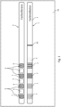
- the Figure 1 shows a color indicator 1 for immersion in a liquid.
- a color indicator 1 can be used, for example, to determine the pH value or other measured variables.
- the example shows a color indicator 1 for determining the free fatty acids in frying oil.
- a color indicator is available, for example, as a test strip from 3M TM under the name LRSM 200.
- the color indicator 1 has four indicator fields 2, which are arranged equidistantly from one another on a base support 3.
- the indicator fields 2 have different sensitivities in this color indicator 1, so that a specific measured value can be determined by the number of indicator fields 2 with a color change. However, the color change is partly gradual.
- the color indicator 1 has a marking 10 which indicates a maximum immersion depth.
- the Fig. 1 further shows a color reference 4, which is also arranged on a strip-shaped base support 3.
- the color reference 4 has four reference fields 6 in the example. Two of the reference fields 6 have a first final color 7 and the other two reference fields 6 have a second final color 8.
- the reference fields 6 with the two final colors are arranged alternately on the base support 3.
- a white color balance field 9 is arranged between two adjacent reference fields 6, which can be used for automatic white balance of an image.
- the color adjustment fields 9 have the same dimensions as the reference fields 6.
- the reference fields 6 have the same distances from one another as the indicator fields 2, so that a reference field 6 can be arranged next to an indicator field 2, as in Fig. 1 shown. This can reduce color deviations due to uneven lighting and thus improve color mapping.
- the color reference can also be placed elsewhere.
- the Fig. 2 shows a flowchart of an advantageous one Method according to the invention.
- the content of free fatty acids in a frying fat or oil in a deep fryer is to be determined.
- the LRSM 200 test strips described above are used as a color indicator.
- the method can also be used without modification to determine other measured variables using other color indicators.
- the color indicator 1 is first immersed in the liquid to be tested, in the example the frying fat, up to the mark 10, so that all indicator fields 2 are wetted with the frying fat 5.
- the color indicator 1 and a color reference 4 are imaged.
- the color indicator 1 and the color reference 4 are captured simultaneously in an image 18.
- the color indicator 1 and the color reference 4 can be placed next to each other on a surface, such as in Fig. 1 shown. This has the advantage that all recording parameters, such as the camera perspective and the lighting, are the same for color indicator 1 and color reference 4, so that any disruptive influences may have less relevance or can be eliminated.
- the color reference 4 is preferably adapted to the color indicator 1 in such a way that the reference fields 6 have approximately the same dimensions and the same distances as the indicator fields 2 of the color indicator 1.
- the image is captured digitally, for example with a smartphone camera, or at least provided to the method in digital form.
- the method according to the invention can be designed in a separate device or as an application program for execution on a mobile device, in particular a smartphone or a tablet computer.
- a color scale is determined from the reference fields 6.
- the color scale is defined by the first final color 7 and the second final color 8.
- the color scale can also be defined by more than two final colors, in particular with one or more intermediate colors being defined. This may increase the number of reference fields required.
- the color values of the color matching fields 9 are determined.
- the color values can be read from the digital image 18 in a usual format, for example as RGB or HSV values.
- color balance fields 9 preferably each have the same color and serve to color balance the recorded image 18.
- the color balance fields 9 can, for example, be white for automatic white balance or gray for gray balance. However, white and gray color matching fields 9 can also be present, so that a double color matching can be carried out. There may also be a colored color matching field, for example in a color complementary to the two final colors, which also enables precise color matching.
- the spaced arrangement of several color adjustment fields 9 also makes it possible to compensate for uneven illumination of the image, which can arise, for example, when the image is taken at an angle due to different distances.
- the color values of the indicator fields 2 are determined.
- the color values are expediently determined here in the same format as the color values of the color matching fields 9.
- the reference fields 6 and the color adjustment fields 9 a method for pattern recognition, edge and/or corner recognition or another known method for object recognition can be used.
- the advantage here is that the color indicator 1 and the color reference 4 can be imaged in almost any position and arrangement relative to one another. This makes the application very simple and less prone to errors.
- a position reference on the color indicator 1 and/or the color reference 4 of which the relative position to the other fields is known.
- a position reference can be, for example, a special symbol or a QR code.
- the color reference 4 can be arranged in a defined position relative to the color indicator 1.
- the color reference 4 can, for example, have a recess for inserting the color indicator 1.
- each indicator field 2 is based on the color value and the indicator field 2 assigned color gradient model determines an intermediate value.
- the intermediate value can already have the physical dimension of the measured value to be determined.
- a measured value is therefore determined from the initial data based on artificial intelligence (AI).
- AI artificial intelligence
- the AI is based on a statistical machine learning process that was trained through many individual measurements.
- the AI has all determined color values and intermediate values as input parameters. Accordingly, such an AI is only designed to evaluate a specific color indicator together with a color reference.
Landscapes
- Engineering & Computer Science (AREA)
- Physics & Mathematics (AREA)
- Theoretical Computer Science (AREA)
- General Physics & Mathematics (AREA)
- Computer Vision & Pattern Recognition (AREA)
- Software Systems (AREA)
- Chemical & Material Sciences (AREA)
- Data Mining & Analysis (AREA)
- Artificial Intelligence (AREA)
- Mathematical Physics (AREA)
- General Engineering & Computer Science (AREA)
- Computing Systems (AREA)
- Medical Informatics (AREA)
- Evolutionary Computation (AREA)
- Multimedia (AREA)
- Signal Processing (AREA)
- Health & Medical Sciences (AREA)
- Chemical Kinetics & Catalysis (AREA)
- Plasma & Fusion (AREA)
- Pathology (AREA)
- Immunology (AREA)
- Life Sciences & Earth Sciences (AREA)
- General Health & Medical Sciences (AREA)
- Biochemistry (AREA)
- Analytical Chemistry (AREA)
- Spectrometry And Color Measurement (AREA)
Description
- Die Erfindung betrifft ein Verfahren zum Bestimmen des Messwertes einer Messgröße einer Substanz mit Hilfe eines Farbindikators, wobei der Farbindikator wenigstens ein Indikatorfeld aufweist, das zuvor mit der Substanz in Kontakt gebracht wurde.
- Ein solches Verfahren kann beispielsweise zur Untersuchung einer Flüssigkeit angewandt werden, wobei auf einem Teststreifen oder Testträger eine Substanz in einem Indikatorfeld vorgehalten ist, die in Abhängigkeit von einer Eigenschaft der Flüssigkeit eine Farbänderung oder ein Farbumschlag zeigt.
- Derartige Untersuchungsverfahren sind bekannt und werden beispielsweise zur Untersuchung des Anteils von freien Fettsäuren oder von polaren Anteilen in Frittieröl verwendet. Farbumschläge dieser Art sind jedoch auch gebräuchlich bei der Untersuchung von anderen Substanzen und Messwerten, beispielsweise den pH-Wert einer Flüssigkeit. Es hat sich hierbei bewährt, dem Benutzer eine Farbskala als Farbreferenz mitzugeben, mit welcher er eine Farbänderung oder Färbung des Indikatorfeldes bewerten kann.
- Dies hat allerdings den Nachteil, dass derartige Farbänderungen graduell erfolgen, sodass eine genaue Einordnung, um wie viel die Farbänderung erfolgt ist, schwierig ist. Zudem stimmen die Farben der Indikatorfelder nicht exakt mit der Farbskala überein, wodurch eine Zuordnung zu einem Messwert zusätzlich erschwert wird.
- Die Erfindung hat demnach die Aufgabe eine einfachere und insbesondere wesentlich genauere Bestimmung eines Messwertes zu ermöglichen.
- Diese Aufgabe wird erfindungsgemäß durch die Verfahrensschritte gemäß dem Anspruch 1 gelöst.
- Das erfindungsgemäße Verfahren ist demnach dadurch gekennzeichnet, dass der Farbindikator und eine Farbreferenz bildlich erfasst werden, wobei die Farbreferenz wenigstens zwei verschiedenfarbige Referenzfelder aufweist, dass computerunterstützt anhand der aufgenommenen Farbwerte der Referenzfelder und des Indikatorfeldes ein Zwischenwert der Messgröße ermittelt wird und dass der Messwert der Substanz aus diesem Zwischenwert ermittelt wird.
- Das bildliche Erfassen kann beispielsweise mit einer herkömmlichen Digitalkamera oder einem Smartphone erfolgen.
- Der Vorteil besteht nun darin, dass die Farbwerte der Farbindikatorfelder nicht mehr visuell erfasst und mit einer Farbreferenz verglichen werden müssen.
- Vielmehr wird aus dem Bild der Farbwert des Indikatorfeldes ermittelt. Anhand der aufgenommenen Farbwerte der Referenzfelder wird computerunterstützt dieser Farbwert des Indikatorfeldes einem Zwischenwert zugewiesen. Der Zwischenwert besitzt vorzugsweise dieselbe physikalische Dimension wie der zu bestimmende Messwert. Aus dem Zwischenwert wird dann computerunterstützt der Messwert ermittelt.
- Insbesondere vorteilhaft ist es, wenn die Indikatorfelder und die Referenzfelder automatisch erkannt werden, beispielsweise durch eine Muster- oder Kantenerkennung oder anhand einer vorgegebenen Lage in Bezug auf eine Lagereferenz. Eine solche Lagereferenz kann beispielsweise gesondert gekennzeichnet sein, so dass sie eindeutig identifiziert werden kann.
- Je nach Farbindikator nehmen die Indikatorfelder unterschiedliche Farben an. Die Farben können dabei graduell variieren oder diskrete Farbwerte annehmen.
- Erfindungsgemäß definieren jeweils zwei verschiedenfarbige Referenzfelder die Endfarben einer Farbskala. Auf diese Weise ist durch wenige Referenzfelder eine ganze Skala der potentiellen Farben der Indikatorfelder definierbar. Erfindungsgemäß sind die Endfarben jeweils einem Endwert des Messbereichs des Farbindikators zugeordnet. Bei einem pH-Farbindikator kann der Messbereich beispielsweise zwischen einem pH-Wert von 1 bis 10 liegen. Dementsprechend können die Endfarben etwa blau für pH 10 und rot für pH 1 sein. Zwischenwerte des Messbereichs können auf diese Weise der Farbskala entnommen oder zugeordnet werden.
- Erfindungsgemäß wird der Zwischenwert durch Interpolation des Farbwertes des Indikatorfeldes innerhalb der Farbskala und der zugeordneten Endwerte ermittelt
- Die Farbindikatoren unterliegen vielfältigen Schwankungen, beispielsweise durch Produktion und/oder Anwendung, so dass die ermittelten Zwischenwerte einer großen statistischen Schwankung unterliegen. In einer besonders vorteilhaften Ausführung erfolgt das Ermitteln des Zwischenwertes und/oder des Messwertes aus dem Zwischenwert anhand von statistischen Methoden und/oder durch eine künstliche Intelligenz. Auf diese Weise kann durch Mittelung über viele Einzelmessungen eine statistische Anpassung erfolgen, so dass ein genauerer Messwert ermittelt wird. Insbesondere bei der Verwendung einer künstlichen Intelligenz (KI) ist eine signifikante Verbesserung der Messgenauigkeit möglich.
- Die künstliche Intelligenz kann als Eingang den Farbwert und/oder Zwischenwert jedes Indikatorfeldes und den Farbwert jedes Referenzfeldes erhalten und als Ausgang den Messwert der Substanz liefern. Auf diese Weise können sehr viele Umgebungseinflüsse in die Ermittlung des Messwertes einfließen. Die künstliche Intelligenz ist aber demnach jeweils immer nur für genau eine Kombination aus Farbindikator und Farbreferenz einsetzbar. Das bedeutet, dass für einen Farbindikator, der eine andere Messgröße und andere Farbwerte aufweist eine eigene künstliche Intelligenz trainiert werden muss.
- In einer vorteilhaften Weiterbildung kann jeder ermittelte Messwert zum weiteren Training der künstlichen Intelligenz verwendet werden.
- Zur Verbesserung der Bestimmung der Farbwerte kann es vorteilhaft sein, wenn ein automatischer Farbabgleich, insbesondere Weißabgleich, vorgenommen wird. Der Farbabgleich kann beispielsweise durch eine interne Kameralogik bei oder nach der Bildaufnahme vorgenommen werden.
- In einer vorteilhaften Ausführung weist die Farbreferenz wenigstens ein Farbabgleichsfeld auf, das als Basis für den Farbabgleich dient. Dieses Farbabgleichsfeld kann beispielsweise weiß für einen Weißabgleich oder grau für einen Grauabgleich sein. Der Farbabgleich kann beispielsweise erfolgen, bevor die Farbwerte der Indikatorfelder und der Referenzfelder bestimmt werden.
- Es ist jedoch auch möglich, dass die Farbwerte der Farbabgleichsfelder als weitere Eingänge der künstlichen Intelligenz dienen. Auf diese Weise erfolgt der automatische Farbabgleich durch die künstliche Intelligenz.
- Prinzipiell ist es möglich, den Farbindikator und die Farbreferenz in separaten Bildern zu erfassen. Jedoch haben Aufnahmeparameter wie Kamerapose, Abstand zum Objekt, Winkel zum Objekt, Brennweite, Blende, Belichtungszeit, ISO-Empfindlichkeit, Beleuchtung usw. Einfluss auf die Ermittlung der Farbwerte. Um diese Aufnahmeparameter gleich zu halten, ist es daher zweckmäßig, wenn die bildliche Erfassung des Farbindikators und der Farbreferenz gleichzeitig, insbesondere in einem Bild, erfolgt. Dadurch ist eine Variation der oben genannten Aufnahmeparameter minimiert oder ausgeschlossen, so dass die Ermittlung der Farbwerte genauer erfolgen kann.
- Für eine erhöhte Genauigkeit bei der Auswertung ist es vorteilhaft, wenn der Farbindikator mehr als ein Indikatorfeld aufweist. Auf diese Weise können beispielsweise fertigungstechnische Abweichungen der Indikatorfelder in die Ermittlung des Messwertes mit einfließen.
- Zweckmäßig kann es daher sein, wenn der Farbindikator wenigstens zwei, insbesondere vier, Indikatorfelder aufweist. Diese Indikatorfelder können gleich sein, so dass für die Auswertung jeweils mehrere redundante Informationen zur Verfügung stehen und damit ein genaueres Ergebnis erzielbar ist.
- In einer Ausführung der Erfindung besitzen die Indikatorfelder unterschiedliche Sensitivitäten gegenüber der zu messenden Substanz. Demnach wechseln die einzelnen Indikatorfelder bei verschiedenen Messwerten ihre Farbe, so dass der Farbindikator eine räumliche Dimension erhält, wodurch eine zusätzliche Verbesserung der Genauigkeit erreicht werden kann.
- In einer vorteilhaften Ausführung weist die Farbreferenz mehr als ein Referenzfeld für jede Endfarbe auf. Diese können beispielsweise entsprechend zu den Indikatorfeldern auf dem Farbindikator voneinander beabstandet sein. Auf diese Weise können Ausleuchtungsunterschiede der Indikatorfelder innerhalb des Bildes und beispielsweise geometrische Verzerrungen berücksichtigt und kompensiert werden.
- Besonders zweckmäßig ist es, wenn die mehreren Referenzfelder einer Endfarbe jeweils identische Farben aufweisen. Insbesondere zweckmäßig ist es, wenn für jede Endfarbe zwei Referenzfelder vorhanden sind, die voneinander beabstandet und/oder abwechselnd angeordnet sind. Durch eine abwechselnde Anordnung kann eine bessere Verteilung der Referenzfelder erzielt werden, so dass Abweichungen im Bild wie oben beschrieben kompensierbar sind.
- Ein Farbindikator ist in der Regel dazu ausgebildet in eine Flüssigkeit getaucht zu werden oder mit einer Flüssigkeit benetzt zu werden. Dadurch können je nach Aufnahmepose Reflexionen entstehen, die im schlechtesten Fall ein Auswerten der Farbe eines Indikatorfelds oder eines Referenzfeldes erschweren oder unmöglich machen.
- In einer Ausführung ist der Farbindikator deshalb so ausgebildet, dass die zu messende Substanz so gebunden wird, dass keine Reflexionen durch Umgebungslicht entstehen. Dazu kann ein Grundträger des Farbindikators saugfähig sein oder eine raue Oberfläche aufweisen.
- In einer Ausführung können Mittel zum Erkennen störender Reflexionen vorhanden sein, so dass beispielsweise eine Warnung ausgegeben werden kann. Solche Mittel können beispielsweise bereits vor der Bildaufnahme Reflexionen erkennen und den Benutzer darauf hinweisen, so dass die Kamerapose und/oder die Beleuchtung gewechselt werden kann.
- Es kann auch vorgesehen sein, dass Reflexionen aus einem bestehenden Bild durch entsprechende Bildbearbeitungsalgorithmen herausgerechnet werden, wodurch jedoch die Genauigkeit leiden kann.
- Prinzipiell ist es möglich, dass der Farbindikator und die Farbreferenz einteilig oder mehrteilig ausgebildet sind. Vorteilhaft ist es dabei, wenn die Farbreferenz separat ausgebildet ist, da diese dann mehrfach wiederverwendbar ist. In einer zweckmäßigen Ausführung sind die Größe und die Abstände der Referenzfelder der Größe beziehungsweise den Abständen der Indikatorfelder angepasst, insbesondere wobei die Abstände identisch sind, so dass die Referenzfelder jeweils neben ein Indikatorfeld platzierbar sind. Dadurch kann die Genauigkeit der erfassten Farbwerte verbessert werden, da die Farbwerte, aufgrund der lokal gleichen Beleuchtung, eine geringere Abweichung aufweisen können.
- Die Erfindung umfasst weiter eine Vorrichtung zum Bestimmen des Messwertes einer Eigenschaft einer Substanz mit Hilfe eines Farbindikators. Diese Vorrichtung ist erfindungsgemäß dadurch gekennzeichnet, dass die Vorrichtung eine Bilderfassungseinheit zur bildlichen Erfassung des Farbindikators und einer Farbreferenz, und eine Auswerteeinheit zur computerunterstützten Ermittlung eines Zwischenwertes anhand der aufgenommenen Farbwerte der Referenzfelder der Farbreferenz und eines Indikatorfeldes des Farbindikators und zur Ermittlung des Messwerts der Substanz aus diesem Zwischenwert aufweist.
- Die erfindungsgemäße Vorrichtung ist in Anspruch 10 definiert.
- Besonders vorteilhaft ist die Vorrichtung zur Durchführung eines erfindungsgemäßen Verfahrens ausgebildet.
- Die Vorrichtung kann als speziell angepasstes Messgerät ausgebildet sein. Besonders vorteilhaft ist es jedoch, wenn die Vorrichtung ein Smartphone, ein Tablet oder ein Notebook ist, bei dem die Auswerteeinheit durch ein Softwareprogramm oder eine App ausgebildet ist. Smartphones sind weit verbreitet und besitzen in der Regel eine Bildaufnahmeeinheit, so dass eine erfindungsgemäße Ermittlung eines Messwertes einfach und kostengünstig durchführbar ist. Der weitere Vorteil besteht darin, dass Updates und/oder Verbesserungen an der Messwertermittlung jederzeit durch ein Softwareupdate umsetzbar sind.
- Die Erfindung ist nachfolgend anhand einer beispielhaften Ausführung mit Bezug auf die beiliegenden Zeichnungen näher erläutert.
- Es zeigt:
- Fig. 1:
- einen Farbindikator und eine Farbreferenz in Form von Teststreifen,
- Fig. 2:
- ein Ablaufdiagramm eines erfindungsgemäßen Verfahrens und
- Fig. 3:
- eine erfindungsgemäße Vorrichtung.
- Die
Figur 1 zeigt einen Farbindikator 1 zum Eintauchen in eine Flüssigkeit. Ein solcher Farbindikator 1 kann beispielsweise zur Bestimmung des pH-Wertes oder anderer Messgrößen eingesetzt werden. - Im Beispiel ist ein Farbindikator 1 zur Bestimmung der freien Fettsäuren in Frittieröl gezeigt. Ein solcher Farbindikator ist beispielsweise als Teststreifen von 3M™ unter der Bezeichnung LRSM 200 verfügbar. Der Farbindikator 1 besitzt vier Indikatorfelder 2, die äquidistant voneinander beabstandet auf einem Grundträger 3 angeordnet sind.
- Die Indikatorfelder 2 besitzen bei diesem Farbindikator 1 unterschiedliche Sensitivitäten, so dass ein bestimmter Messwert durch die Anzahl der Indikatorfelder 2 mit Farbumschlag bestimmt werden kann. Dabei erfolgt der Farbumschlag jedoch zum Teil graduell.
- Der Farbindikator 1 besitzt eine Markierung 10, die eine maximale Eintauchtiefe anzeigt.
- Die
Fig. 1 zeigt weiter eine Farbreferenz 4, die ebenfalls auf einem streifenförmigen Grundträger 3 angeordnet ist. Die Farbreferenz 4 weist im Beispiel vier Referenzfelder 6 auf. Zwei der Referenzfelder 6 besitzen eine erste Endfarbe 7 und die beiden anderen Referenzfelder 6 besitzen eine zweite Endfarbe 8. Die Referenzfelder 6 mit den beiden Endfarben sind dabei abwechselnd auf dem Grundträger 3 angeordnet. - Im Beispiel ist jeweils zwischen zwei benachbarten Referenzfeldern 6 ein weißes Farbabgleichsfeld 9 angeordnet, das für einen automatischen Weißabgleich eines Bildes verwendet werden kann. Die Farbabgleichsfelder 9 besitzen im Beispiel die gleichen Abmessungen wie die Referenzfelder 6.
- Insbesondere besitzen die Referenzfelder 6 die gleichen Abstände zueinander wie die Indikatorfelder 2, so dass jeweils ein Referenzfeld 6 neben ein Indikatorfeld 2 anordenbar ist, wie in
Fig. 1 gezeigt. Dadurch können Farbabweichungen aufgrund von ungleichmäßiger Beleuchtung reduziert und damit die Farbzuordnung verbessert werden. Die Farbreferenz kann jedoch auch an anderer Stelle platziert werden. - Die
Fig. 2 zeigt ein Ablaufdiagramm eines vorteilhaften Verfahrens gemäß der Erfindung. Im Beispiel soll der Gehalt an freien Fettsäuren in einem Frittierfett oder Frittieröl einer Fritteuse bestimmt werden. Dazu werden die oben beschriebenen LRSM 200 Teststreifen als Farbindikator verwendet. Das Verfahren ist ohne Änderung auch zur Bestimmung von anderen Messgrößen unter Verwendung von anderen Farbindikatoren anwendbar. - Der Farbindikator 1 wird dazu zunächst bis zur Markierung 10 in die zu testende Flüssigkeit, im Beispiel das Frittierfett, eingetaucht, so dass alle Indikatorfelder 2 mit Frittierfett 5 benetzt sind.
- In einem Bilderfassungsschritt 11 werden der Farbindikator 1 und eine Farbreferenz 4 bildlich erfasst. Vorzugsweise werden der Farbindikator 1 und die Farbreferenz 4 gleichzeitig in einem Bild 18 erfasst.
- Dazu können der Farbindikator 1 und die Farbreferenz 4 nebeneinander auf eine Oberfläche platziert werden, wie beispielsweise in
Fig. 1 gezeigt. Dies hat den Vorteil, dass alle Aufnahmeparameter, wie etwa die Kameraperspektive und die Beleuchtung, für Farbindikator 1 und Farbreferenz 4 gleich sind, so dass eventuell störende Einflüsse eine geringere Relevanz aufweisen oder herausgerechnet werden können. - Vorzugsweise ist die Farbreferenz 4 dem Farbindikator 1 so angepasst, dass die Referenzfelder 6 etwa die gleichen Abmessungen und die gleichen Abstände aufweisen, wie die Indikatorfelder 2 des Farbindikators 1.
- Es ist jedoch auch möglich den Farbindikator 1 und die Farbreferenz 4 separat aufzunehmen, wodurch jedoch die oben genannten Vorteile eventuell nicht vorhanden sind.
- Besonders zweckmäßig ist es dabei, wenn das Bild digital erfasst wird, beispielsweise mit einer Smartphone-Kamera oder zumindest in digitaler Form dem Verfahren bereitgestellt wird.
- Das erfindungsgemäße Verfahren kann in einem separaten Gerät oder als Anwendungsprogramm zur Ausführung auf einem mobilen Gerät, insbesondere einem Smartphone oder einem Tablet-Computer, ausgebildet sein.
- In einem Farbskalaschritt 12 wird aus den Referenzfeldern 6 eine Farbskala ermittelt. Die Farbskala wird dabei durch die erste Endfarbe 7 und die zweite Endfarbe 8 definiert.
- Zwischenfarbwerte der Farbskala werden dabei durch Farbinterpolation bestimmt. Hierbei können verschiedene Farbmodelle verwendet werden, wobei die Wahl des Farbmodells von der Art der Farbindikatoren abhängen kann.
- Je nach Art des Farbindikators kann die Farbskala auch durch mehr als zwei Endfarben definiert sein, insbesondere wobei eine oder mehrere Zwischenfarben definiert sind. Die Anzahl der notwendigen Referenzfelder erhöht sich dadurch eventuell.
- In einem Farbabgleichsschritt 13 werden die Farbwerte der Farbabgleichsfelder 9 ermittelt. Die Farbwerte können dabei in einem üblichen Format, etwa als RGB- oder HSV-Werte, aus dem digitalen Bild 18 ausgelesen werden.
- Diese Farbabgleichsfelder 9 weisen vorzugsweise jeweils die gleiche Farbe auf und dienen zum Farbabgleich des aufgenommenen Bildes 18. Die Farbabgleichsfelder 9 können beispielsweise weiß für einen automatischen Weißabgleich oder grau für einen Grauabgleich sein. Es können jedoch auch weiße und graue Farbabgleichsfelder 9 vorhanden sein, so dass ein doppelter Farbabgleich durchgeführt werden kann. Es kann auch ein farbiges Farbabgleichsfeld vorhanden sein, beispielsweise in einer zu den beiden Endfarben komplementären Farbe, wodurch ebenfalls ein genauer Farbabgleich möglich ist. Durch die beabstandete Anordnung von mehreren Farbabgleichsfeldern 9 ist zusätzlich ein Ausgleich einer ungleichmäßigen Ausleuchtung des Bildes möglich, die beispielsweise bei einer schrägen Bildaufnahme durch unterschiedliche Abstände entstehen kann.
- In einem Indikatorschritt 14 werden die Farbwerte der Indikatorfelder 2 ermittelt. Die Farbwerte werden hier zweckmäßigerweise im selben Format ermittelt, wie die Farbwerte der Farbabgleichsfelder 9.
- Zur automatischen Ermittlung der Farbwerte der Indikatorfelder 2, der Referenzfelder 6 und der Farbabgleichsfelder 9 kann ein Verfahren zur Mustererkennung, Kanten- und/oder Eckenerkennung oder ein anderes bekanntes Verfahren zur Objekterkennung angewendet werden. Der Vorteil dabei ist, dass der Farbindikator 1 und die Farbreferenz 4 in nahezu beliebiger Lage und Anordnung zueinander bildlich erfasst werden können. Dadurch wird die Anwendung sehr einfach und wenig fehleranfällig.
- Es kann jedoch auch auf dem Farbindikator 1 und/oder der Farbreferenz 4 eine Lagereferenz vorhanden sein, von der die relative Lage zu den anderen Feldern bekannt ist. Eine solche Lagereferenz kann beispielsweise ein spezielles Symbol oder etwa ein QR-Code sein.
- Es ist auch möglich, dass die Farbreferenz 4 in einer definierten Lage zum Farbindikator 1 angeordnet ist. Die Farbreferenz 4 kann beispielsweise eine Aussparung zum Einlegen des Farbindikators 1 aufweisen.
- In einem Modellschritt 15 wird für jedes Indikatorfeld 2 anhand des Farbwertes und eines dem Indikatorfeld 2 zugeordneten Farbverlaufsmodell ein Zwischenwert bestimmt. Der Zwischenwert kann dabei bereits die physikalische Dimension des zu bestimmenden Messwertes besitzen.
- Diese Zwischenwerte sind einer großen statistischen Schwankung unterlegen. Insbesondere da die Sensitivitäten der einzelnen Indikatorfelder nicht genau herstellbar sind und weil die Farbwechsel nur graduell erfolgen.
- Daher ist eine analytische Bestimmung eines Messwertes nur schwer möglich. In einem Auswerteschritt 16 wird daher auf Grundlage einer künstlichen Intelligenz (KI) aus den Ausgangsdaten ein Messwert ermittelt.
- Die KI basiert auf einem statistischen, maschinellen Lernverfahren, das durch viele Einzelmessungen trainiert wurde. Insbesondere besitzt die KI als Eingangsparameter alle ermittelten Farbwerte und Zwischenwerte. Demnach ist eine solche KI nur zur Auswertung eines bestimmten Farbindikators zusammen mit einer Farbreferenz ausgebildet.
- Andere Farbindikatoren mit einer unterschiedlichen Anzahl an Indikatorfeldern benötigen jeweils eine eigens trainierte KI.
- Es kann zweckmäßig sein, wenn jeder durchgeführte Messvorgang zum weiteren Training der KI verwendet wird. Dazu kann es vorteilhaft sein, wenn die KI beispielsweise auf einem zentralen Server als Webdienst ausgebildet ist, so dass alle Apps von der kontinuierlichen Verbesserung gleichermaßen profitieren.
-
- 1
- Farbindikator
- 2
- Indikatorfeld
- 3
- Grundträger
- 4
- Farbreferenz
- 5
- Frittierfett
- 6
- Referenzfeld
- 7
- erste Endfarbe
- 8
- zweite Endfarbe
- 9
- Farbabgleichsfeld
- 10
- Markierung
- 11
- Bilderfassungsschritt
- 12
- Skalaschritt
- 13
- Farbabgleichsschritt
- 14
- Indikatorschritt
- 15
- Modellschritt
- 16
- Auswerteschritt
- 17
- Messwert
- 18
- Bild
- 19
- Vorrichtung
- 20
- Bilderfassungseinheit
- 21
- Auswerteeinheit
Claims (11)
- Verfahren zum Bestimmen des Messwertes einer Messgröße einer Substanz mit Hilfe eines Farbindikators (1), wobei der Farbindikator (1) wenigstens ein Indikatorfeld (2) aufweist, das zuvor mit der Substanz in Kontakt gebracht wurde, wobei der Farbindikator (1) und eine Farbreferenz (4) bildlich (18) erfasst (11) werden, wobei die Farbreferenz (4) wenigstens zwei verschiedenfarbige Referenzfelder (6) aufweist, dadurch gekennzeichnet, dass computerunterstützt anhand der aufgenommenen Farbwerte der Referenzfelder (6) und des Indikatorfeldes (2) ein Zwischenwert der Messgröße ermittelt wird (15), wobei jeweils zwei verschiedenfarbige Referenzfelder (6) die Endfarben (7, 8) einer Farbskala definieren und die Endfarben (7, 8) jeweils einem Endwert des Messbereichs des Farbindikators (1) zugeordnet sind und wobei der Zwischenwert durch Interpolation des Farbwertes des Indikatorfeldes (2) innerhalb der Farbskala und der zugeordneten Endwerte ermittelt wird, und dass der Messwert der Substanz aus diesem Zwischenwert ermittelt wird (16).
- Verfahren nach Anspruch 1, dadurch gekennzeichnet, dass das Ermitteln (16) des Messwertes aus dem Zwischenwert anhand von statistischen Methoden und/oder durch eine künstliche Intelligenz erfolgt.
- Verfahren nach Anspruch 2, dadurch gekennzeichnet, dass die künstliche Intelligenz (16) als Eingang den Farbwert und/oder den Zwischenwert jedes Indikatorfeldes (2) und den Farbwert jedes Referenzfeldes (6) erhält und als Ausgang den Messwert der Substanz liefert.
- Verfahren nach einem der Ansprüche 1 bis 3, dadurch gekennzeichnet, dass ein automatischer Farbabgleich, insbesondere Weißabgleich, vorgenommen wird, insbesondere wobei die Farbreferenz wenigstens ein Farbabgleichsfeld (9) aufweist und/oder dass die Farbwerte der Farbabgleichsfelder (9) als weitere Eingänge der künstlichen Intelligenz (16) dienen.
- Verfahren nach einem der Ansprüche 1 bis 4, dadurch gekennzeichnet, dass die bildliche Erfassung (11) des Farbindikators (1) und der Farbreferenz (4) gleichzeitig, insbesondere in einem Bild (18), erfolgt.
- Verfahren nach einem der Ansprüche 1 bis 5, dadurch gekennzeichnet, dass der Farbindikator (1) mehr als ein Indikatorfeld (2), insbesondere vier Indikatorfelder (2), aufweist, insbesondere wobei die Indikatorfelder (2) unterschiedliche Sensitivitäten gegenüber der zu messenden Substanz aufweisen.
- Verfahren nach einem der Ansprüche 1 bis 6, dadurch gekennzeichnet, dass die Farbreferenz (4) mehr als ein Referenzfeld (6) für jede Endfarbe (7, 8) aufweist, wobei die Referenzfelder (6) einer Endfarbe (7, 8) jeweils identische Farben aufweisen, insbesondere wobei für jede Endfarbe (7, 8) zwei Referenzfelder (6) vorhanden sind, die voneinander beabstandet und abwechselnd angeordnet sind.
- Verfahren nach einem der Ansprüche 1 bis 7, dadurch gekennzeichnet, dass der Farbindikator (1) so ausgebildet ist, dass die zu messende Substanz so gebunden wird, dass keine Reflexionen durch Umgebungslicht entstehen und/oder dass Mittel zum Erkennen störender Reflexionen vorhanden sind, so dass eine Warnung ausgegeben werden kann.
- Verfahren nach einem der Ansprüche 1 bis 8, dadurch gekennzeichnet, dass der Farbindikator (1) und die Farbreferenz (4) einteilig oder mehrteilig ausgebildet sind und/oder dass die Größe und die Abstände der Referenzfelder (6) der Größe und den Abständen der Indikatorfelder (2) angepasst sind, insbesondere wobei die Abstände identisch sind, so dass die Referenzfelder (6) jeweils neben ein Indikatorfeld (2) platzierbar sind.
- Vorrichtung (19) zum Bestimmen des Messwertes einer Eigenschaft einer Substanz mit Hilfe eines Farbindikators (1) und einer Farbreferenz (4), wobei die Vorrichtung (19) eine Bilderfassungseinheit (20) zur bildlichen Erfassung des Farbindikators (1) und einer Farbreferenz (4), und eine Auswerteeinheit (21) zur computerunterstützten Ermittlung eines Zwischenwertes anhand der aufgenommenen Farbwerte der Referenzfelder (6) der Farbreferenz (4) und eines Indikatorfeldes (2) des Farbindikators (1) enthält, 11
dadurch charakterisiert dass
jeweils zwei verschiedenfarbige Referenzfelder (6) die Endfarben (7, 8) einer Farbskala definieren und die Endfarben (7, 8) jeweils einem Endwert des Messbereichs des Farbindikators (1) zugeordnet sind und wobei die Vorrichtung so ausgebildet ist, dass die Ermittlung des Zwischenwertes durch Interpolation des Farbwertes des Indikatorfeldes (2) innerhalb der Farbskala und der zugeordneten Endwerte erfolgt, und der Messwert der Substanz aus diesem Zwischenwert bestimmt wird . - Vorrichtung (19) nach Anspruch 10, dadurch gekennzeichnet, dass die Vorrichtung (19) ein Smartphone, ein Tablet oder ein Notebook ist, bei dem die Auswerteeinheit (21) durch ein Softwareprogramm oder eine App ausgebildet ist.
Applications Claiming Priority (1)
| Application Number | Priority Date | Filing Date | Title |
|---|---|---|---|
| DE102019123474.3A DE102019123474A1 (de) | 2019-09-02 | 2019-09-02 | Verfahren zum Auswerten eines Farbindikators |
Publications (2)
| Publication Number | Publication Date |
|---|---|
| EP3785633A1 EP3785633A1 (de) | 2021-03-03 |
| EP3785633B1 true EP3785633B1 (de) | 2023-10-18 |
Family
ID=72603307
Family Applications (1)
| Application Number | Title | Priority Date | Filing Date |
|---|---|---|---|
| EP20193743.0A Active EP3785633B1 (de) | 2019-09-02 | 2020-08-31 | Verfahren und vorrichtung zum auswerten eines farbindikators |
Country Status (3)
| Country | Link |
|---|---|
| US (1) | US11836949B2 (de) |
| EP (1) | EP3785633B1 (de) |
| DE (1) | DE102019123474A1 (de) |
Family Cites Families (17)
| Publication number | Priority date | Publication date | Assignee | Title |
|---|---|---|---|---|
| GB9700729D0 (en) * | 1997-01-15 | 1997-03-05 | Axis Biochemicals As | System |
| US6673630B2 (en) * | 2000-02-23 | 2004-01-06 | Bayer Corporation | Method and apparatus for producing visual results using colorimetric strips |
| US7277019B2 (en) * | 2004-10-29 | 2007-10-02 | Motorola, Inc. | Universal colorimetric imaging array device |
| DE102009010665A1 (de) * | 2009-02-27 | 2010-09-16 | Beiersdorf Ag | Verwendung von geladenen Tensiden zur Verminderung der Textilverfleckung durch Antitranspirantien |
| CN102539735A (zh) * | 2010-11-12 | 2012-07-04 | 美艾利尔圣地亚哥有限公司 | 集成质量保证标签的测试装置和系统 |
| JP2015509582A (ja) * | 2012-02-03 | 2015-03-30 | ユニバーシティ・オブ・シンシナティ | 比色アッセイを解析するための方法、システム、および装置 |
| US10132802B2 (en) * | 2012-04-17 | 2018-11-20 | i-calQ, LLC | Device for performing a diagnostic test and methods for use thereof |
| WO2013170216A1 (en) * | 2012-05-11 | 2013-11-14 | Wellsense Inc. | Mobile analyte monitoring system |
| US9311520B2 (en) * | 2012-08-08 | 2016-04-12 | Scanadu Incorporated | Method and apparatus for performing and quantifying color changes induced by specific concentrations of biological analytes in an automatically calibrated environment |
| US9285323B2 (en) * | 2012-08-08 | 2016-03-15 | Scanadu Incorporated | Quantifying color changes of chemical test pads induced concentrations of biological analytes under different lighting conditions |
| US9557274B2 (en) * | 2012-08-17 | 2017-01-31 | St. Mary's College | Analytical devices for detection of low-quality pharmaceuticals |
| CN107110786B (zh) * | 2014-12-24 | 2020-10-27 | 皇家飞利浦有限公司 | 使用比色传感器进行的测量和校准 |
| US20170184506A1 (en) * | 2015-12-29 | 2017-06-29 | Pritesh Arjunbhai Patel | Reagent test strips comprising reference regions for measurement with colorimetric test platform |
| DE102016202428B4 (de) * | 2016-02-17 | 2018-06-21 | Axagarius Gmbh & Co. Kg | Messsystem für colorimetrische Assays |
| US20180136140A1 (en) * | 2016-11-15 | 2018-05-17 | Jon Brendsel | System for monitoring and managing biomarkers found in a bodily fluid via client device |
| WO2020005378A1 (en) * | 2018-06-25 | 2020-01-02 | Morgan Ranzy Iii | Liquid color, haze, and clarity instrument, and method of measurement |
| EP3650843B1 (de) * | 2018-11-07 | 2022-01-19 | Roche Diabetes Care GmbH | Verfahren und vorrichtungen zur durchführung einer analytischen messung |
-
2019
- 2019-09-02 DE DE102019123474.3A patent/DE102019123474A1/de not_active Withdrawn
-
2020
- 2020-08-31 EP EP20193743.0A patent/EP3785633B1/de active Active
- 2020-09-01 US US17/008,770 patent/US11836949B2/en active Active
Also Published As
| Publication number | Publication date |
|---|---|
| DE102019123474A1 (de) | 2021-03-04 |
| US11836949B2 (en) | 2023-12-05 |
| EP3785633A1 (de) | 2021-03-03 |
| US20210065403A1 (en) | 2021-03-04 |
Similar Documents
| Publication | Publication Date | Title |
|---|---|---|
| DE102016120026B4 (de) | Messvorrichtung und Verfahren, Programm, Produktherstellungsverfahren, Kalibrierungsmarkierungselement, Verarbeitungsvorrichtung und Verarbeitungssystem | |
| EP4072808B1 (de) | Computergestütztes verfahren und einrichtung zur prüfung einer sichtbetonqualität | |
| EP4046595B1 (de) | Verfahren zur festlegung einer zahnfarbe | |
| DE10157958A1 (de) | Bildverarbeitungsverfahren und-vorrichtung | |
| EP3830660B1 (de) | Verfahren und assistenzsystem zur parametrisierung eines anomalieerkennungsverfahrens | |
| DE102018109276A1 (de) | Bildhintergrundsubtraktion für dynamische beleuchtungsszenarios | |
| DE102018122961A1 (de) | Chromatographische datensystemverarbeitungseinrichtung | |
| DE10241936A1 (de) | Farbwertkorrektur bei einer Farbkalibrierung | |
| EP4303807A1 (de) | Verfahren, mess-system und computerprogrammprodukt zur farbprüfung | |
| DE112018000224T5 (de) | Verfahren und Vorrichtung zum Positionieren von Probenschlitzen | |
| DE102016100134A1 (de) | Verfahren und Vorrichtung zum Untersuchen eines Objekts unter Verwendung von maschinellem Sehen | |
| DE19951146A1 (de) | Verfahren zum Reduzieren des Rauschens in einem durch Abbildung erhaltenen Signal | |
| DE102023119420A1 (de) | Verfahren zur Erfassung von freien Enden von Steckspulen in einem Stator | |
| EP3553503B1 (de) | Analyseverfahren und anschmutzung | |
| DE102015225018A1 (de) | Verfahren zur Prüfung einer Mehrzahl von in gleicher Weise mit Bauteilen bestückten Bauteilträgern, Computerprogrammprodukt zur Durchführung eines solchen Verfahrens, und Prüfsystem zur Durchführung eines solchen Verfahrens | |
| EP3785633A1 (de) | Verfahren zum auswerten eines farbindikators | |
| DE102018133092B3 (de) | Computer-implementiertes Verfahren zur Analyse von Messdaten aus einer Messung eines Objektes | |
| DE112020006612T5 (de) | Vorrichtung zur messung dreidimensionaler form, verfahren zur messung dreidimensionaler form und programm | |
| EP1104995B1 (de) | Verfahren zur automatischen kontrolle und selektion von geflügelschlachttierkörpern | |
| EP3771564B1 (de) | Druckinspektionsvorrichtung und verfahren zur optischen inspektion eines druckbildes eines druckobjekts | |
| EP2199765B1 (de) | Verfahren und Handfarbmessgerät zur Ausmessung einer Farbmesstafel | |
| DE102006042956B4 (de) | Verfahren zur optischen Inspektion und Visualisierung der von scheibenförmigen Objekten gewonnenen optischen Messwerte | |
| DE102004034398B4 (de) | Verfahren zum Ermitteln einer linearen Beziehung aus elektronisch speicherbaren Meßdaten | |
| EP3097400B1 (de) | Verfahren zur steuerung einer beleuchtungsanordnung | |
| DE4318692A1 (de) | Verfahren zur Untersuchung von antigenhaltigen Blutserumproben |
Legal Events
| Date | Code | Title | Description |
|---|---|---|---|
| PUAI | Public reference made under article 153(3) epc to a published international application that has entered the european phase |
Free format text: ORIGINAL CODE: 0009012 |
|
| STAA | Information on the status of an ep patent application or granted ep patent |
Free format text: STATUS: THE APPLICATION HAS BEEN PUBLISHED |
|
| AK | Designated contracting states |
Kind code of ref document: A1 Designated state(s): AL AT BE BG CH CY CZ DE DK EE ES FI FR GB GR HR HU IE IS IT LI LT LU LV MC MK MT NL NO PL PT RO RS SE SI SK SM TR |
|
| AX | Request for extension of the european patent |
Extension state: BA ME |
|
| STAA | Information on the status of an ep patent application or granted ep patent |
Free format text: STATUS: REQUEST FOR EXAMINATION WAS MADE |
|
| 17P | Request for examination filed |
Effective date: 20210819 |
|
| RBV | Designated contracting states (corrected) |
Designated state(s): AL AT BE BG CH CY CZ DE DK EE ES FI FR GB GR HR HU IE IS IT LI LT LU LV MC MK MT NL NO PL PT RO RS SE SI SK SM TR |
|
| RIC1 | Information provided on ipc code assigned before grant |
Ipc: G01N 33/03 20060101ALI20230325BHEP Ipc: G06T 7/90 20170101ALI20230325BHEP Ipc: G01N 21/78 20060101ALI20230325BHEP Ipc: G01N 31/22 20060101ALI20230325BHEP Ipc: A61B 5/1473 20060101ALI20230325BHEP Ipc: A61B 5/1459 20060101ALI20230325BHEP Ipc: A61B 5/145 20060101AFI20230325BHEP |
|
| GRAP | Despatch of communication of intention to grant a patent |
Free format text: ORIGINAL CODE: EPIDOSNIGR1 |
|
| STAA | Information on the status of an ep patent application or granted ep patent |
Free format text: STATUS: GRANT OF PATENT IS INTENDED |
|
| INTG | Intention to grant announced |
Effective date: 20230509 |
|
| P01 | Opt-out of the competence of the unified patent court (upc) registered |
Effective date: 20230323 |
|
| GRAS | Grant fee paid |
Free format text: ORIGINAL CODE: EPIDOSNIGR3 |
|
| GRAA | (expected) grant |
Free format text: ORIGINAL CODE: 0009210 |
|
| STAA | Information on the status of an ep patent application or granted ep patent |
Free format text: STATUS: THE PATENT HAS BEEN GRANTED |
|
| AK | Designated contracting states |
Kind code of ref document: B1 Designated state(s): AL AT BE BG CH CY CZ DE DK EE ES FI FR GB GR HR HU IE IS IT LI LT LU LV MC MK MT NL NO PL PT RO RS SE SI SK SM TR |
|
| REG | Reference to a national code |
Ref country code: GB Ref legal event code: FG4D Free format text: NOT ENGLISH |
|
| REG | Reference to a national code |
Ref country code: CH Ref legal event code: EP |
|
| REG | Reference to a national code |
Ref country code: DE Ref legal event code: R096 Ref document number: 502020005678 Country of ref document: DE |
|
| REG | Reference to a national code |
Ref country code: IE Ref legal event code: FG4D Free format text: LANGUAGE OF EP DOCUMENT: GERMAN |
|
| REG | Reference to a national code |
Ref country code: LT Ref legal event code: MG9D |
|
| REG | Reference to a national code |
Ref country code: NL Ref legal event code: MP Effective date: 20231018 |
|
| PG25 | Lapsed in a contracting state [announced via postgrant information from national office to epo] |
Ref country code: NL Free format text: LAPSE BECAUSE OF FAILURE TO SUBMIT A TRANSLATION OF THE DESCRIPTION OR TO PAY THE FEE WITHIN THE PRESCRIBED TIME-LIMIT Effective date: 20231018 |
|
| PG25 | Lapsed in a contracting state [announced via postgrant information from national office to epo] |
Ref country code: GR Free format text: LAPSE BECAUSE OF FAILURE TO SUBMIT A TRANSLATION OF THE DESCRIPTION OR TO PAY THE FEE WITHIN THE PRESCRIBED TIME-LIMIT Effective date: 20240119 |
|
| PG25 | Lapsed in a contracting state [announced via postgrant information from national office to epo] |
Ref country code: IS Free format text: LAPSE BECAUSE OF FAILURE TO SUBMIT A TRANSLATION OF THE DESCRIPTION OR TO PAY THE FEE WITHIN THE PRESCRIBED TIME-LIMIT Effective date: 20240218 |
|
| PG25 | Lapsed in a contracting state [announced via postgrant information from national office to epo] |
Ref country code: LT Free format text: LAPSE BECAUSE OF FAILURE TO SUBMIT A TRANSLATION OF THE DESCRIPTION OR TO PAY THE FEE WITHIN THE PRESCRIBED TIME-LIMIT Effective date: 20231018 |
|
| PG25 | Lapsed in a contracting state [announced via postgrant information from national office to epo] |
Ref country code: ES Free format text: LAPSE BECAUSE OF FAILURE TO SUBMIT A TRANSLATION OF THE DESCRIPTION OR TO PAY THE FEE WITHIN THE PRESCRIBED TIME-LIMIT Effective date: 20231018 |
|
| PG25 | Lapsed in a contracting state [announced via postgrant information from national office to epo] |
Ref country code: LT Free format text: LAPSE BECAUSE OF FAILURE TO SUBMIT A TRANSLATION OF THE DESCRIPTION OR TO PAY THE FEE WITHIN THE PRESCRIBED TIME-LIMIT Effective date: 20231018 Ref country code: IS Free format text: LAPSE BECAUSE OF FAILURE TO SUBMIT A TRANSLATION OF THE DESCRIPTION OR TO PAY THE FEE WITHIN THE PRESCRIBED TIME-LIMIT Effective date: 20240218 Ref country code: GR Free format text: LAPSE BECAUSE OF FAILURE TO SUBMIT A TRANSLATION OF THE DESCRIPTION OR TO PAY THE FEE WITHIN THE PRESCRIBED TIME-LIMIT Effective date: 20240119 Ref country code: ES Free format text: LAPSE BECAUSE OF FAILURE TO SUBMIT A TRANSLATION OF THE DESCRIPTION OR TO PAY THE FEE WITHIN THE PRESCRIBED TIME-LIMIT Effective date: 20231018 Ref country code: BG Free format text: LAPSE BECAUSE OF FAILURE TO SUBMIT A TRANSLATION OF THE DESCRIPTION OR TO PAY THE FEE WITHIN THE PRESCRIBED TIME-LIMIT Effective date: 20240118 Ref country code: PT Free format text: LAPSE BECAUSE OF FAILURE TO SUBMIT A TRANSLATION OF THE DESCRIPTION OR TO PAY THE FEE WITHIN THE PRESCRIBED TIME-LIMIT Effective date: 20240219 |
|
| PG25 | Lapsed in a contracting state [announced via postgrant information from national office to epo] |
Ref country code: SE Free format text: LAPSE BECAUSE OF FAILURE TO SUBMIT A TRANSLATION OF THE DESCRIPTION OR TO PAY THE FEE WITHIN THE PRESCRIBED TIME-LIMIT Effective date: 20231018 Ref country code: RS Free format text: LAPSE BECAUSE OF FAILURE TO SUBMIT A TRANSLATION OF THE DESCRIPTION OR TO PAY THE FEE WITHIN THE PRESCRIBED TIME-LIMIT Effective date: 20231018 Ref country code: PL Free format text: LAPSE BECAUSE OF FAILURE TO SUBMIT A TRANSLATION OF THE DESCRIPTION OR TO PAY THE FEE WITHIN THE PRESCRIBED TIME-LIMIT Effective date: 20231018 Ref country code: NO Free format text: LAPSE BECAUSE OF FAILURE TO SUBMIT A TRANSLATION OF THE DESCRIPTION OR TO PAY THE FEE WITHIN THE PRESCRIBED TIME-LIMIT Effective date: 20240118 Ref country code: LV Free format text: LAPSE BECAUSE OF FAILURE TO SUBMIT A TRANSLATION OF THE DESCRIPTION OR TO PAY THE FEE WITHIN THE PRESCRIBED TIME-LIMIT Effective date: 20231018 Ref country code: HR Free format text: LAPSE BECAUSE OF FAILURE TO SUBMIT A TRANSLATION OF THE DESCRIPTION OR TO PAY THE FEE WITHIN THE PRESCRIBED TIME-LIMIT Effective date: 20231018 |
|
| PG25 | Lapsed in a contracting state [announced via postgrant information from national office to epo] |
Ref country code: DK Free format text: LAPSE BECAUSE OF FAILURE TO SUBMIT A TRANSLATION OF THE DESCRIPTION OR TO PAY THE FEE WITHIN THE PRESCRIBED TIME-LIMIT Effective date: 20231018 |
|
| REG | Reference to a national code |
Ref country code: DE Ref legal event code: R097 Ref document number: 502020005678 Country of ref document: DE |
|
| PG25 | Lapsed in a contracting state [announced via postgrant information from national office to epo] |
Ref country code: CZ Free format text: LAPSE BECAUSE OF FAILURE TO SUBMIT A TRANSLATION OF THE DESCRIPTION OR TO PAY THE FEE WITHIN THE PRESCRIBED TIME-LIMIT Effective date: 20231018 |
|
| PG25 | Lapsed in a contracting state [announced via postgrant information from national office to epo] |
Ref country code: SK Free format text: LAPSE BECAUSE OF FAILURE TO SUBMIT A TRANSLATION OF THE DESCRIPTION OR TO PAY THE FEE WITHIN THE PRESCRIBED TIME-LIMIT Effective date: 20231018 |
|
| PG25 | Lapsed in a contracting state [announced via postgrant information from national office to epo] |
Ref country code: SM Free format text: LAPSE BECAUSE OF FAILURE TO SUBMIT A TRANSLATION OF THE DESCRIPTION OR TO PAY THE FEE WITHIN THE PRESCRIBED TIME-LIMIT Effective date: 20231018 Ref country code: SK Free format text: LAPSE BECAUSE OF FAILURE TO SUBMIT A TRANSLATION OF THE DESCRIPTION OR TO PAY THE FEE WITHIN THE PRESCRIBED TIME-LIMIT Effective date: 20231018 Ref country code: RO Free format text: LAPSE BECAUSE OF FAILURE TO SUBMIT A TRANSLATION OF THE DESCRIPTION OR TO PAY THE FEE WITHIN THE PRESCRIBED TIME-LIMIT Effective date: 20231018 Ref country code: IT Free format text: LAPSE BECAUSE OF FAILURE TO SUBMIT A TRANSLATION OF THE DESCRIPTION OR TO PAY THE FEE WITHIN THE PRESCRIBED TIME-LIMIT Effective date: 20231018 Ref country code: EE Free format text: LAPSE BECAUSE OF FAILURE TO SUBMIT A TRANSLATION OF THE DESCRIPTION OR TO PAY THE FEE WITHIN THE PRESCRIBED TIME-LIMIT Effective date: 20231018 Ref country code: DK Free format text: LAPSE BECAUSE OF FAILURE TO SUBMIT A TRANSLATION OF THE DESCRIPTION OR TO PAY THE FEE WITHIN THE PRESCRIBED TIME-LIMIT Effective date: 20231018 Ref country code: CZ Free format text: LAPSE BECAUSE OF FAILURE TO SUBMIT A TRANSLATION OF THE DESCRIPTION OR TO PAY THE FEE WITHIN THE PRESCRIBED TIME-LIMIT Effective date: 20231018 |
|
| PLBE | No opposition filed within time limit |
Free format text: ORIGINAL CODE: 0009261 |
|
| STAA | Information on the status of an ep patent application or granted ep patent |
Free format text: STATUS: NO OPPOSITION FILED WITHIN TIME LIMIT |
|
| 26N | No opposition filed |
Effective date: 20240719 |
|
| PG25 | Lapsed in a contracting state [announced via postgrant information from national office to epo] |
Ref country code: SI Free format text: LAPSE BECAUSE OF FAILURE TO SUBMIT A TRANSLATION OF THE DESCRIPTION OR TO PAY THE FEE WITHIN THE PRESCRIBED TIME-LIMIT Effective date: 20231018 |
|
| PG25 | Lapsed in a contracting state [announced via postgrant information from national office to epo] |
Ref country code: SI Free format text: LAPSE BECAUSE OF FAILURE TO SUBMIT A TRANSLATION OF THE DESCRIPTION OR TO PAY THE FEE WITHIN THE PRESCRIBED TIME-LIMIT Effective date: 20231018 |
|
| REG | Reference to a national code |
Ref country code: CH Ref legal event code: PL |
|
| PG25 | Lapsed in a contracting state [announced via postgrant information from national office to epo] |
Ref country code: LU Free format text: LAPSE BECAUSE OF NON-PAYMENT OF DUE FEES Effective date: 20240831 |
|
| PG25 | Lapsed in a contracting state [announced via postgrant information from national office to epo] |
Ref country code: MC Free format text: LAPSE BECAUSE OF FAILURE TO SUBMIT A TRANSLATION OF THE DESCRIPTION OR TO PAY THE FEE WITHIN THE PRESCRIBED TIME-LIMIT Effective date: 20231018 Ref country code: CH Free format text: LAPSE BECAUSE OF NON-PAYMENT OF DUE FEES Effective date: 20240831 |
|
| REG | Reference to a national code |
Ref country code: BE Ref legal event code: MM Effective date: 20240831 |
|
| PG25 | Lapsed in a contracting state [announced via postgrant information from national office to epo] |
Ref country code: BE Free format text: LAPSE BECAUSE OF NON-PAYMENT OF DUE FEES Effective date: 20240831 |
|
| PG25 | Lapsed in a contracting state [announced via postgrant information from national office to epo] |
Ref country code: IE Free format text: LAPSE BECAUSE OF NON-PAYMENT OF DUE FEES Effective date: 20240831 |
|
| PG25 | Lapsed in a contracting state [announced via postgrant information from national office to epo] |
Ref country code: FI Free format text: LAPSE BECAUSE OF FAILURE TO SUBMIT A TRANSLATION OF THE DESCRIPTION OR TO PAY THE FEE WITHIN THE PRESCRIBED TIME-LIMIT Effective date: 20231019 |
|
| PGFP | Annual fee paid to national office [announced via postgrant information from national office to epo] |
Ref country code: DE Payment date: 20250827 Year of fee payment: 6 |
|
| PGFP | Annual fee paid to national office [announced via postgrant information from national office to epo] |
Ref country code: GB Payment date: 20250826 Year of fee payment: 6 |
|
| PGFP | Annual fee paid to national office [announced via postgrant information from national office to epo] |
Ref country code: AT Payment date: 20251020 Year of fee payment: 5 Ref country code: FR Payment date: 20250825 Year of fee payment: 6 |
|
| PG25 | Lapsed in a contracting state [announced via postgrant information from national office to epo] |
Ref country code: CY Free format text: LAPSE BECAUSE OF FAILURE TO SUBMIT A TRANSLATION OF THE DESCRIPTION OR TO PAY THE FEE WITHIN THE PRESCRIBED TIME-LIMIT; INVALID AB INITIO Effective date: 20200831 |
|
| PG25 | Lapsed in a contracting state [announced via postgrant information from national office to epo] |
Ref country code: HU Free format text: LAPSE BECAUSE OF FAILURE TO SUBMIT A TRANSLATION OF THE DESCRIPTION OR TO PAY THE FEE WITHIN THE PRESCRIBED TIME-LIMIT; INVALID AB INITIO Effective date: 20200831 |