EP3784037B1 - Flexibler behälter zur lagerung und zum transport von biopharmazeutika - Google Patents
Flexibler behälter zur lagerung und zum transport von biopharmazeutika Download PDFInfo
- Publication number
- EP3784037B1 EP3784037B1 EP18723321.8A EP18723321A EP3784037B1 EP 3784037 B1 EP3784037 B1 EP 3784037B1 EP 18723321 A EP18723321 A EP 18723321A EP 3784037 B1 EP3784037 B1 EP 3784037B1
- Authority
- EP
- European Patent Office
- Prior art keywords
- polymer
- port
- collapsible
- port assembly
- pouch
- Prior art date
- Legal status (The legal status is an assumption and is not a legal conclusion. Google has not performed a legal analysis and makes no representation as to the accuracy of the status listed.)
- Active
Links
Images


Classifications
-
- A—HUMAN NECESSITIES
- A01—AGRICULTURE; FORESTRY; ANIMAL HUSBANDRY; HUNTING; TRAPPING; FISHING
- A01N—PRESERVATION OF BODIES OF HUMANS OR ANIMALS OR PLANTS OR PARTS THEREOF; BIOCIDES, e.g. AS DISINFECTANTS, AS PESTICIDES OR AS HERBICIDES; PEST REPELLANTS OR ATTRACTANTS; PLANT GROWTH REGULATORS
- A01N1/00—Preservation of bodies of humans or animals, or parts thereof
- A01N1/10—Preservation of living parts
- A01N1/14—Mechanical aspects of preservation; Apparatus or containers therefor
- A01N1/146—Non-refrigerated containers specially adapted for transporting or storing living parts whilst preserving
- A01N1/147—Carriers for immersion in cryogenic fluid for slow freezing or vitrification
-
- A—HUMAN NECESSITIES
- A61—MEDICAL OR VETERINARY SCIENCE; HYGIENE
- A61J—CONTAINERS SPECIALLY ADAPTED FOR MEDICAL OR PHARMACEUTICAL PURPOSES; DEVICES OR METHODS SPECIALLY ADAPTED FOR BRINGING PHARMACEUTICAL PRODUCTS INTO PARTICULAR PHYSICAL OR ADMINISTERING FORMS; DEVICES FOR ADMINISTERING FOOD OR MEDICINES ORALLY; BABY COMFORTERS; DEVICES FOR RECEIVING SPITTLE
- A61J1/00—Containers specially adapted for medical or pharmaceutical purposes
- A61J1/05—Containers specially adapted for medical or pharmaceutical purposes for collecting, storing or administering blood, plasma or medical fluids ; Infusion or perfusion containers
- A61J1/10—Bag-type containers
-
- A—HUMAN NECESSITIES
- A61—MEDICAL OR VETERINARY SCIENCE; HYGIENE
- A61J—CONTAINERS SPECIALLY ADAPTED FOR MEDICAL OR PHARMACEUTICAL PURPOSES; DEVICES OR METHODS SPECIALLY ADAPTED FOR BRINGING PHARMACEUTICAL PRODUCTS INTO PARTICULAR PHYSICAL OR ADMINISTERING FORMS; DEVICES FOR ADMINISTERING FOOD OR MEDICINES ORALLY; BABY COMFORTERS; DEVICES FOR RECEIVING SPITTLE
- A61J1/00—Containers specially adapted for medical or pharmaceutical purposes
- A61J1/14—Details; Accessories therefor
- A61J1/1468—Containers characterised by specific material properties
-
- A—HUMAN NECESSITIES
- A61—MEDICAL OR VETERINARY SCIENCE; HYGIENE
- A61J—CONTAINERS SPECIALLY ADAPTED FOR MEDICAL OR PHARMACEUTICAL PURPOSES; DEVICES OR METHODS SPECIALLY ADAPTED FOR BRINGING PHARMACEUTICAL PRODUCTS INTO PARTICULAR PHYSICAL OR ADMINISTERING FORMS; DEVICES FOR ADMINISTERING FOOD OR MEDICINES ORALLY; BABY COMFORTERS; DEVICES FOR RECEIVING SPITTLE
- A61J1/00—Containers specially adapted for medical or pharmaceutical purposes
- A61J1/14—Details; Accessories therefor
- A61J1/1475—Inlet or outlet ports
- A61J1/1487—Inlet or outlet ports with friction fit, e.g. connecting tubes directly to a protruding port
-
- A—HUMAN NECESSITIES
- A61—MEDICAL OR VETERINARY SCIENCE; HYGIENE
- A61J—CONTAINERS SPECIALLY ADAPTED FOR MEDICAL OR PHARMACEUTICAL PURPOSES; DEVICES OR METHODS SPECIALLY ADAPTED FOR BRINGING PHARMACEUTICAL PRODUCTS INTO PARTICULAR PHYSICAL OR ADMINISTERING FORMS; DEVICES FOR ADMINISTERING FOOD OR MEDICINES ORALLY; BABY COMFORTERS; DEVICES FOR RECEIVING SPITTLE
- A61J1/00—Containers specially adapted for medical or pharmaceutical purposes
- A61J1/14—Details; Accessories therefor
- A61J1/1462—Containers with provisions for hanging, e.g. integral adaptations of the container
Definitions
- the present disclosure relates to storage bags and, in particular, to storage bags for freezing, thawing, storing, and transporting biological products.
- Single-use flexible containers are used for transportation, storage, freezing, and thawing of materials, such as biologics.
- Some such containers are flexible bags that are made out of plastic film.
- the bags may be used for storage, particularly in cryopreservation applications.
- the bags are typically disposable to reduce risk of cross contamination and the need for cleaning validation.
- US 2016/0030283 A1 discloses a storage bag formed of a composite tube that has an inner surface comprising a higher melting polymer and an outer surface comprising a lower melting polymer. A molded piece having ports is attached to the bag after formation of the composite tube.
- a storage bag particularly for cryogenic applications, having improved durability, reduced leakage, and reduced interaction between plastic extractables and contained drug substances is therefore desirable.
- the disclosure is directed to a storage bag that includes a collapsible pouch including an internal volume and an aperture at one end; a non-collapsible port assembly; a port reinforcing laminate overlapping the port assembly and the end of the collapsible pouch including the aperture; and at least one peripheral cavity.
- the non-collapsible port assembly includes a body that may be elongate in a lateral direction relative to the pouch, and a snout that may be elongate in the longitudinal direction relative to the pouch, and the body includes at least two conduits passing therethrough.
- the port reinforcing laminate retains the port assembly with the body spaced apart from the collapsible pouch and the snout extending from the body into the internal volume through the aperture.
- the peripheral cavity is formed by the port reinforcing laminate and a portion of the port assembly and extends from the edge of the collapsible pouch to at least one conduit so the conduit is in fluid communication with the internal volume through the peripheral cavity.
- the non-collapsible port includes a plurality of conduits, optionally two conduits, where a first conduit is a filling conduit and a second conduit is an extraction conduit.
- the non-collapsible port includes a third conduit, where the third conduit may be a sampling conduit.
- the filling conduit, the extraction conduit, the sampling conduit, or any combination thereof extend through the non-collapsible snout.
- at least one conduit is in fluid communication with the internal volume through the non-collapsible snout.
- one or more, e.g., two or more, of the conduits are in fluid communication with the internal volume through the peripheral cavity.
- the port assembly further includes one or more connectors that extend outside the reinforcing laminate for connecting one or more tubes to the port assembly so each tube is in fluid communication with at least one conduit of the port assembly.
- the collapsible pouch has an internal surface formed from a first polymer and an external surface formed from a second polymer, and the relative melting points of the first and second polymers are such that the collapsible pouch can be heated to a temperature high enough to melt bond the second polymer without melting the first polymer.
- the melting point of the first polymer is at least 30 °C higher than the melting point of the second polymer.
- the collapsible pouch is formed of a multilayered composite material having a layer formed from the first polymer and a layer formed from the second polymer.
- the first polymer is a fluoropolymer, such as polytetrafluoroethylene (“PTFE”) or perfluoroalkoxy (“PFA”).
- the first polymer may be a non-fluoropolymer, such as a polyimide (e.g., Kapton ® ).
- the second polymer is a fluoropolymer, such as fluorinated ethylene propylene (“FEP”), polyvinylidene fluoride (“PVDF”), ethylene tetrafluoroethylene (“ETFE”), or ethylene chlorotrifluoroethylene (“ECTFE”).
- the second polymer may be a non-fluoropolymer.
- the first polymer and the second polymer are both fluoropolymers (e.g., the first polymer is PTFE and the second polymer is FEP).
- the non-collapsible port assembly is formed from a fluoropolymer, such as FEP, PVDF, ETFE, or ECTFE. In other examples, the non-collapsible port assembly may be formed from a non-fluoropolymer.
- the reinforcing laminate includes two composite layers, where each layer includes a first surface comprising a third polymer and an opposing second surface comprising a fourth polymer, and the two composite layers are positioned on either side of the port assembly and the collapsible pouch with the second surface of each composite layer in contact with at least a portion of the non-collapsible port assembly and at least a portion of the collapsible pouch.
- the relative melting points of the third and fourth polymers are such that the composite layers can be heated to a temperature high enough to melt bond the fourth polymer without melting the third polymer.
- the melting point of the third polymer is at least 30 °C higher than the melting point of the fourth polymer.
- the third polymer is a fluoropolymer, such as PTFE or PFA.
- the third polymer may be a non-fluoropolymer, such as a polyimide (e.g., Kapton ® ).
- the fourth polymer is a fluoropolymer, such as FEP, PVDF, ETFE, or ECTFE.
- the fourth polymer may be a non-fluoropolymer.
- the third polymer and the fourth polymer are both fluoropolymers (e.g., the third polymer is PTFE and the fourth polymer is FEP).
- the two layers of the port reinforcing laminate are positioned on either side of the port assembly and the end of the collapsible pouch with the fourth polymer in contact with the port assembly and the collapsible pouch.
- the fourth polymer may bond the two composite layers to an external surface of the collapsible pouch, to the port assembly, and/or to each other.
- the end of the collapsible pouch overlapped by the reinforcing laminate comprises a joint, and the reinforcing laminate covers the joint.
- locating the end of the collapsible pouch between the two composite layers and locating the portion of the port assembly between the two composite layers are both carried out before melt bonding the port reinforcing laminate to the portion of the collapsible pouch and to the portion of the port assembly, and melt bonding the port reinforcing laminate to the portion of the collapsible pouch and to the portion of the port assembly are carried out as a single step.
- melt bonding the two composite layers to the portion of the port assembly forms at least one peripheral cavity extending from the collapsible pouch to at least one conduit so the at least one conduit is in fluid communication with the internal volume through the peripheral cavity.
- melt bonding the two composite layers to the collapsible pouch and melt bonding the two composite layers to the portion of the port assembly secures the port assembly with the body spaced apart from the collapsible pouch and the snout extending from the body into the internal volume through the aperture.
- a storage bag including first, second, and third, composite sheets, where the first composite sheet is in the shape of a collapsible pouch surrounding an internal volume, and where the first composite sheet includes a plurality of edges that overlap or abut at joints to form the collapsible pouch.
- the collapsible pouch formed by the first composite sheet includes a substantially planar top surface, a substantially planar bottom surface, two opposing sides, and first and second ends, where the sides and ends form a periphery of the collapsible pouch; a lap seam on the top or the bottom surface extending from a point adjacent to the first end to a point adjacent to the second end, where the lap seam includes two opposing edges of the first composite sheet that overlap; a first series of joints on the top or the bottom surface and adjacent to the first end, where the first series of joints includes a first plurality of edges of the first composite sheet that abut; and a second series of joints on the top or the bottom surface and adjacent to the second end, where the second series of joints includes a second plurality of edges of the first composite sheet that abut.
- the second composite sheet is disposed across the first series of joints to form a first series of lap seams; the third composite sheet is disposed across the second series of joints to form a second series of lap seams; and the first end of the collapsible pouch includes at least one aperture having an area.
- the at least one aperture has an area greater than 0.11 square inches. In some aspects, the sum of the areas of all of the apertures is less than 0.55 square inches.
- Described herein are storage bags, such as cryopreservation bags, and methods of making the bags.
- the bags are used to freeze, store, and transport biologic materials.
- a fluid including a biologic material may be introduced to the bag through a conduit and then frozen for storage and/or transport, after which the fluid may be thawed and extracted from the bag through the same or a different conduit.
- the storage bags described herein advantageously limit the volume of fluid in the port area of the bag to minimize or even prevent fluid expansion that is extensive enough to cause delamination failures.
- the bags include a collapsible pouch having an internal volume where the fluid is contained and at least one aperture through which fluid can be introduced and extracted.
- the structure of the storage bags as described herein allows efficient filling and draining even with an aperture smaller than that of known storage bags.
- the aperture has an area greater than 0.11 square inches.
- each aperture has an area and the sum of the areas of all of the apertures is less than 0.55 square inches.
- the bags include a separate non-collapsible port assembly outside the pouch but fluidly connected thereto.
- the non-collapsible port assembly includes a body that may be elongate in a lateral direction relative to the pouch, and a snout that may be elongate in the longitudinal direction relative to the pouch, and the body includes one or more conduits passing therethrough.
- the collapsible pouch and non-collapsible port assembly are sandwiched between layers of a port reinforcing laminate that maintains a desired position of the port assembly relative to the pouch with the body spaced apart from the pouch and the snout contacting the aperture or extending through the aperture into the internal volume of the pouch.
- the port reinforcing laminate and a portion of the port assembly define a peripheral cavity adjacent to the port assembly and between two layers of the laminate.
- the peripheral cavity extends from the pouch to the conduit(s) in the body, and the conduit(s) are in fluid communication with the internal volume through the peripheral cavity.
- the small volume of the peripheral cavity results in low stress on seams in the port area because the small volume of fluid has little change in volume upon freezing, and thus low change in stress on the seams, during the freeze cycle. This minimizes or even prevents delamination failures at the port that might otherwise be caused by expansion of trapped fluid when freezing.
- the structure and materials of the bags (including the pouch, the port assembly, and the laminate) provide improved durability, reduced leakage, and reduced interaction between plastic extractables and drug substances stored in the bags.
- high melting polymer and “higher melting polymer” mean a polymer that does not melt when heated to a temperature high enough to melt bond another polymer referred to herein as a "low melting polymer” or “lower melting polymer.”
- the "high melting polymer” or “higher melting polymer” is a polymer having a melting point that is from about 30°C to about 80°C greater than a melting point the "low melting polymer” or “lower melting polymer.”
- the “low melting polymer” or “lower melting polymer” means a polymer that can be melt bonded at a temperature where the "high melting polymer” or “higher melting polymer” does not melt.
- the "low melting polymer” or “lower melting polymer” is a polymer having a melting point that is from about 30°C to about 80°C less than the melting point of the "high melting polymer” or “higher melting polymer.”
- joint means an interface that includes two abutting edges, edges that are in near abutment, or edges that overlap.
- Lap seam as used herein means a seam having edges that overlap one another.
- “Cryopreservation” as used herein means storage or preservation at temperatures below 0 °C.
- Collapsible as used herein means a material or component easily changes shape, for example flattens, under an applied force.
- Non-collapsible as used herein means a material retains its shape under an applied force.
- a storage bag disclosed herein includes a collapsible pouch with an internal volume and an aperture (i.e., an opening), a non-collapsible port assembly, and a port reinforcing laminate that is a composite sheet that overlaps, bonds to, and maintains the relative spacing of the pouch and the port assembly.
- the port reinforcing laminate includes two layers, where the two layers are positioned on opposite sides of the collapsible pouch, on opposite sides of the aperture, and on opposite sides of the non-collapsible port assembly.
- the non-collapsible port assembly includes a body that may be elongate in a lateral direction relative to the pouch, and a snout that may be elongate in the longitudinal direction relative to the pouch.
- the port assembly and the end of the pouch lie between layers of the reinforcing laminate with the snout extending into the internal volume of the collapsible pouch through the aperture and the body spaced apart from the pouch.
- the body includes at least one conduit that is in fluid communication with the internal volume of the pouch through a peripheral cavity formed by a portion of the snout (e.g., a side portion of the snout) and layers of the reinforcing laminate.
- a storage bag may include more than one reinforcing laminate, for example one containing the port assembly and maintaining its spacing relative to the collapsible pouch and another in a different location that may include a handle.
- a reinforcing laminate contains the port assembly, it is referred to herein as a port reinforcing laminate.
- a reinforcing laminate contains a handle, it may be referred to herein as a handle reinforcing laminate to distinguish it from the port reinforcing laminate.
- the collapsible pouch is formed from a polymer material that remains durable even at very low temperatures and that also has a low level of extractables.
- the durable polymer with low extractables may be a first polymer in a composite material that also includes a second polymer that facilitates construction of the bag, for example by having a lower melting point.
- first polymer forms the inner surface of the pouch and the second polymer forms the exterior surface of the pouch.
- the first polymer forms the entire inner surface of the collapsible pouch, so a contained fluid contacts only the first polymer and not the second polymer.
- the first polymer may form a continuous layer on the inner surface of the collapsible pouch.
- the first polymer provides durability to the storage bag, so even at extremely low temperatures the storage bag does not shatter when dropped.
- the second polymer may have any properties desired for facilitating construction of the bag because the first polymer prevents the second polymer from coming into contact with the contents of the pouch, thereby preventing and/or inhibiting interaction between the contents of the bag and any plastic extractables in the second polymer.
- the first polymer is a fluoropolymer, such as PTFE or PFA.
- the first polymer may be a non-fluoropolymer, such as a polyimide (e.g., Kapton ® ).
- the second polymer is a fluoropolymer, such as FEP, PVDF, ETFE, or ECTFE.
- the second polymer may be a non-fluoropolymer.
- the first polymer and the second polymer are both fluoropolymers (e.g., the first polymer is PTFE and the second polymer is FEP).
- the collapsible pouch of the storage bags disclosed herein includes an internal surface formed from a first polymer and an external surface formed from a second polymer, wherein the relative melting points of the first and second polymers are such that the collapsible pouch can be heated to a temperature high enough to melt bond the second polymer without melting the first polymer.
- the melting point of the first polymer is at least 30 °C higher (e.g., at least 50 °C, or at least 80 °C higher) than the melting point of the second polymer.
- a reinforcing laminate includes two layers formed from one or more sheets, where one sheet may be folded to form the two layers or two sheets may be stacked to form the two layers.
- the sheet(s) are composite materials, each having a first side and a second side, where the first side is formed from a third polymer and the second side is formed from a fourth polymer, wherein the relative melting points of the third and fourth polymers are such that the reinforcing laminate can be heated to a temperature high enough to melt bond the fourth polymer without melting the third polymer.
- the melting point of the third polymer is at least 30 °C higher (e.g., at least 50 °C, or at least 80 °C higher) than the melting point of the fourth polymer.
- the third polymer is a fluoropolymer, such as PTFE or PFA.
- the third polymer may be a non-fluoropolymer, such as a polyimide (e.g., Kapton ® ).
- the fourth polymer is a fluoropolymer, such as FEP, PVDF, ETFE, or ECTFE.
- the fourth polymer may be a non-fluoropolymer.
- the third polymer and the fourth polymer are both fluoropolymers (e.g., the third polymer is PTFE and the fourth polymer is FEP).
- the third and fourth polymers may be the same as the first and second polymers described above for the collapsible pouch, or they may be different.
- the two layers of a port reinforcing laminate are disposed on opposing sides of the pouch and the port assembly such that the second side (i.e., the low melting polymer side) of each layer faces the pouch and the port assembly, and the low melting polymer can bond with the pouch and at least a portion of the port assembly when heat is applied.
- Bonding the port reinforcing laminate to the pouch can be carried out in the same step or in a separate step from bonding the port reinforcing laminate to the port assembly.
- the port reinforcing laminate is raised to a temperature between the melting temperature of the third polymer and the melting temperature of the fourth polymer.
- the outer surface of the pouch is formed from a polymer having a sufficiently low melting point
- that polymer can contribute to the bonding between the pouch and the port reinforcing laminate.
- the outer surface of the port assembly is formed from a polymer having a sufficiently low melting point
- that polymer can contribute to the bonding between the port assembly and the port reinforcing laminate.
- the reinforcing laminate when a port reinforcing laminate is disposed over a joint or seam between two materials that form the collapsible pouch, the reinforcing laminate can seal the joint or reinforce the seal of the seam. Reinforcing laminates other than the port reinforcing laminate may be used to seal other joints or reinforce other seams and/or for other purposes, such as to incorporate a handle.
- the two composite layers of a reinforcing laminate are formed from a single composite sheet that is folded over.
- the two composite layers of a reinforcing laminate are two separate composite sheets, where one sheet is disposed on each side of the collapsible pouch. The reinforcing laminate provides enhanced leak protection at the ends and the corners of the storage bag and provides additional strength to the storage bag, particularly when the fluid in the storage bag is frozen.
- the two composite layers can bond with each other when heat is applied.
- the composite layers do not contact each other in a region immediately adjacent to the port assembly, so they do not bond in that region. Rather, the region immediately adjacent the snout remains open, forming a peripheral cavity.
- at least one peripheral cavity is provided adjacent a side of the port assembly and extends from the collapsible pouch to a conduit of the port assembly such that the conduit is in fluid communication with the interior volume of the collapsible pouch through the peripheral cavity.
- the port reinforcing laminate bonds to the body of the port assembly and to the snout, forming two peripheral cavities with one on either side of the snout.
- the port reinforcing laminate bonds to the body of the port assembly, but does not bind to the snout or does not bind to all of the snout, forming one peripheral cavity that extends from one side of the snout to the other, including above and/or below the snout where the port reinforcing laminate is not bonded to the snout.
- multiple peripheral cavities are provided, e.g., on opposing sides of the snout, in which case each peripheral cavity may be in fluid communication with a separate conduit or conduits in the body of the port assembly.
- Fig. 1A illustrates a partial top view of storage bag 100.
- Fig. 1B is a cross-sectional view along lines 1B-1B of Fig. 1A.
- Fig. 1C is a cross-sectional view along lines 1C-1C of Fig. 1A .
- the body 116 of the non-collapsible port assembly 114 includes two conduits 120A, 120C and is retained in the port reinforcing laminate 108.
- the body 116 is spaced apart from the collapsible pouch 102.
- the snout 118 extends from the body 116 into the interior volume of the collapsible pouch 102. At least a portion of the snout 118 extends between the layers 108A, 108B of the port reinforcing laminate 108.
- the port reinforcing laminate 108 includes first and second composite layers 108A, 108B that are bonded to the collapsible pouch 102 where the layers 108A, 108B contact the collapsible pouch 102 and bonded the port assembly 114 where the layers 108A, and 108B contact the port assembly.
- the layers 108A, 108B are bonded to each other between the collapsible pouch 102 and port assembly 114, except at the peripheral cavity 124 (or 124A, 124B), where the layers 108A, 108B are spaced apart from each other.
- Fig. 1B illustrates a portion of the two distinct peripheral cavities 124A, 124B formed by the snout 118 and the first and second composite layers 108A, 108B when the first and second composite layers are bonded to the top and bottom of the snout.
- Fig. 1C illustrates a portion of the peripheral cavity 124A formed by the body 116 and the first and second composite layers 108A, 108B.
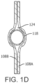
- FIG. 1D illustrates a portion of the single peripheral cavity 124 formed by the snout 118 and the first and second composite layers 108A, 108B when the first and second composite layers are not bonded to the top or the bottom of the snout.
- the single cavity 124 includes open regions on either side of the snout that are in fluid communication through one or more passages defined above and/or below the snout 118.
- the size of a peripheral cavity 124 can be adjusted to control the volume of fluid permitted in the peripheral cavity 124.
- the volume of fluid trapped between the collapsible pouch 102 and the non-collapsible port assembly 114 is limited, and as such this area advantageously experiences limited expansion during freezing.
- the non-collapsible snout 118 inhibits or even prevents film collapse and allows unrestricted flow into and out of the collapsible pouch through the non-collapsible port assembly.
- the non-collapsible port assembly 114 may include one conduit, two conduits, three conduits, or more than three conduits.
- the conduit(s) may extend through the body, through the snout, or a combination thereof.
- a conduit may be defined through the snout with other conduits defined through the body 116; all of the conduits may be defined through the body 116; all of the conduits may be defined through the snout 118; or more than one conduit may be defined through the snout 118 with one or more other conduits defined through the body 116.
- Various other arrangements of conduits may be provided and are considered to be within the purview of the current disclosure.
- one of the conduits of the non-collapsible port assembly is a filling conduit and another of the conduits is an extraction conduit.
- one of the conduits is a sampling conduit; however, in other examples, the sampling conduit may be omitted.
- the filling conduit, extraction conduit, and optionally the sampling conduit may be arranged (e.g., through the body and/or through the snout) in any way desired, and such arrangement should not be considered limiting on the current disclosure.
- Each conduit may include one or more tubes disposed in or through the conduit for providing material to or extracting material from the collapsible pouch 102.
- the port assembly 114 may include connectors that extend outside the reinforcing laminate to connect tubes to the conduits.
- the storage bag 100 may include a filling tube, through which liquids can enter the internal volume, and an extraction tube, through which liquids can be extracted from the internal volume.
- the storage bag may include a sampling tube through which samples can be extracted during filling, freezing, storage, transportation, or extraction.
- the sampling tube is in fluid communication with the internal volume of the collapsible pouch 102 through the body 116 and the snout 118 that extends into the interior volume of the pouch.
- a second reinforcing laminate may be provided at a different location on the collapsible pouch.
- a second reinforcing laminate is provided at the end opposite the aperture.
- this additional reinforcing laminate may include a slit or another opening therein that can be used as a handle to facilitate transporting the pouch.
- This reinforcing laminate may be referred to as a handle reinforcing laminate.
- the handle reinforcing laminate is substantially similar to the port reinforcing laminate.
- the handle reinforcing laminate may include two composite layers, each having a first side and a second side, where the first side includes a higher melting polymer and the second side includes a lower melting polymer.
- the two composite layers of the handle reinforcing laminate are formed from a single sheet that is folded over a portion of the collapsible pouch.
- the two composite layers of the handle reinforcing laminate are two separate composite sheets, where one is disposed on each side of the collapsible pouch and each sheet is arranged with the lower melting second side facing the collapsible pouch.
- the handle reinforcing laminate and the port reinforcing laminate provide enhanced leak protection at ends and corners of the storage bag and provide additional strength to the storage bag, particularly when the storage bag is frozen.
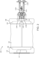
- FIGs. 2 and 3 illustrate an embodiment of a storage bag 100. Elements in common with FIGs 1A-C retain the same numbering.
- the collapsible pouch 102 includes a first end 104, and a port reinforcing laminate 108 overlaps the first end 104.
- the collapsible pouch 102 also includes a handle reinforcing laminate 110 that overlaps a second end 106 and includes a handle 112.
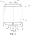
- the non-collapsible port assembly 114 includes three conduits 120A-C, three connectors 129A-C, and three tubes 122A-C disposed over the three connectors 129A-C.
- FIG. 3 omits the tubes so the connectors 129A-C are more clearly visible.
- the conduits 120A and 120B are defined through the body 116 and the conduit 120C is defined through the snout 118.
- one of the conduits 120 e.g.
- conduit 120A) of the non-collapsible port assembly 114 may be a filling conduit, another of the conduits 120 (e.g., conduit 120C) may be an extraction conduit, and another of the conduits 120 (e.g., conduit 120C) may be a sampling conduit.
- the arrangement of the filling conduit, extraction conduit, and optionally the sampling conduit within the storage bag should not be considered limiting on the current disclosure.
- the port assembly 114 may have a substantially T-shape, as shown in FIGs. 2-3 , with a single snout positioned perpendicular to and centered on the body.
- the port assembly 114 may have any convenient or desired shape including an off-set snout (e,g., a snout that is not centered on the body), a snout that is angled with respect to the body (i.e., not perpendiculars to the body), or multiple snouts.
- an off-set snout e.g., a snout that is not centered on the body
- a snout that is angled with respect to the body i.e., not perpendiculars to the body
- multiple snouts e.g., multiple snouts.
- peripheral cavities 124A, 124B are adjacent to opposing side portions of the non-collapsible port assembly 114.
- the peripheral cavities 124A, 124B extend from the aperture of the collapsible pouch 102 to the body 116 of the non-collapsible port assembly such that at least one of the conduits of the non-collapsible port assembly 114 is in fluid communication with the interior volume of the collapsible pouch 102 through the peripheral cavities 124A, 124B.
- the conduit 120A is in fluid communication with the interior volume of the collapsible pouch 102 through the peripheral cavity 124A
- the conduit 120B is in fluid communication with the interior volume of the collapsible pouch 102 through the peripheral cavity 124B
- the conduit 120C is in fluid communication with the interior volume through the snout 118. It will be appreciated that the number and/or location of the peripheral cavities 124A, 124B may be adjusted depending on the number and/or location of the conduits 120.
- the collapsible pouch portion of the storage bag is formed from a flat sheet by rolling the flat sheet into a tube, joining two opposing edges of the sheet, and then sealing the tube at both ends.
- the flat sheet is a composite sheet, having a first surface that includes a first polymer and a second opposing surface that includes a second polymer that has a lower melting point than the first polymer, as described in detail above.
- the tube and collapsible pouch are formed with the first surface of the composite sheet as the internal surface of the tube and collapsible pouch and with the second surface of the composite sheet as the external surface of the tube and collapsible pouch.
- the higher melting polymer forms the internal surface of the tube and the collapsible pouch and the lower melting polymer of the composite sheet forms the external surface of the tube and the collapsible pouch.
- the higher melting polymer imparts the beneficial properties of durability and low extractables discussed above, and the lower melting polymer facilitates construction of the tube, the collapsible pouch, and the storage bag, because it can be softened or melted to form bonds.
- the higher melting polymer is a non-melt processible polymer including, but not limited to, PTFE, PFA, or a polyimide such as Kapton ® .
- the lower melting polymer is a melt processible polymer including, but not limited to, FEP, PVDF, ETFE, or ECTFE.
- a flat composite sheet is formed into a composite tube by joining two opposing edges of the composite sheet, optionally by overlapping the edges.
- the composite sheet is oriented with the first surface/higher melting polymer toward the inside of the tube and the second surface/lower melting polymer toward the outside of the tube.
- the overlapping edges are joined together by heating the composite material to a temperature between the melting points of the lower melting polymer and the higher melting polymer, so that the lower melting polymer softens or melts but the higher melting polymer does not, applying pressure where the edges overlap, and allowing the lower melting polymer to solidify.
- the overlapping edges form a lap seam.
- the tube is flattened to form a top portion and a bottom portion with the lap seam that joins the opposing edges extending along the top or bottom portion of the tube from one end to another.
- the lap seam extends substantially along the center of the top or bottom portion of the tube from one end to the other.
- the lap seam does not form an edge of the flattened tube (along a periphery of the flattened tube) between the top and bottom portions.
- the flat composite sheet has a substantially rectangular shape, and optionally the two opposing edges to be joined are substantially straight. Once the opposing edges are joined, the other edges of the composite sheet each form an end of the composite tube.
- the edges forming the ends of the tube may include one or more extensions, for example, one or more flaps or contoured portions, for use in closing the ends of the tube to form the collapsible pouch.
- the extensions on the composite sheet are shaped and sized so that once the tube is formed and flattened, the extensions are along only one of the top or bottom portion of each end. Thus, the ends of the top and bottom portions of the tube are off-set.
- composite sheet 200 has a first surface 218 comprising a higher melting polymer.
- the first surface 218 will become the inner surface of the collapsible pouch 102 (shown in FIG. 7B ).
- the composite sheet 200 further includes a second surface (not shown) opposite the first surface 218.
- the second surface includes a lower melting polymer, and the second surface will become the outer surface of the collapsible pouch 102.
- the composite sheet 200 is substantially rectangular with two extensions 210 on opposing sides having extension edges 212. Fold lines J and H indicate where extensions 210 will be folded to close the ends of the collapsible pouch 102.
- One of the fold lines H includes an aperture 219.
- the aperture may be any convenient shape, including circular, oval, or any other desired shape.
- Opposing side portions 216 of the composite sheet 200 will overlap when the composite sheet is rolled to form composite tube 201 (shown in FIG. 5 ).
- extension edges 212 are offset compared to the non-extended edges 214. It should be understood that the specific geometry of extensions 210 is provided as an example only, other geometries are possible, and the exact extension geometry illustrated should not be considered limiting on the present disclosure.
- FIGs. 5-6 show the formation of composite tube 201.
- FIG. 5 shows the composite sheet 200 formed into a ring, optionally around a mandrel, until opposing side portions 216 overlap.
- the composite tube 201 is formed with the first surface 218 (higher melting polymer) of the composite sheet 200 as the internal surface 221 of the composite tube 201 and the second surface (lower melting polymer) of the composite sheet 200 as the external surface 220 of the composite tube 201.
- first surface 218 higher melting polymer
- second surface lower melting polymer
- tube 201 is flattened in a direction perpendicular to diameter D by folding along line K.
- FIG. 6 shows the composite tube 201 flattened prior to folding the extensions 210 to close the ends of the tube 201.
- the extension edges 212 are off-set compared to the non-extended edges 214.
- An end of the tube may be sealed by folding an extension so the edge of the extension abuts or overlaps the edge of the non-extended portion of the tube end to form a joint.
- the extension is folded along a fold line intermediate between the edge of the extension and the edge of the opposing top or bottom portion of the tube. That is, the fold line is within the extension, so that after the extension is folded the joint with the non-extended portion is on the top or bottom of the collapsible pouch, not at the periphery.
- an extension is divided into multiple sections, for example three sections, with different geometries and different fold lines to facilitate folding required to join the top and bottom portions and seal an end of the tube. Each section of an extension can be folded such that the edges of that section abut or overlap another section or abut or overlap the opposing portion of the flattened tube to form a joint.
- FIG. 7A shows a first reinforcing laminate 250 that is placed over an end of the collapsible pouch 102, as shown in FIG. 7B .
- the first reinforcing laminate 250 has a first surface (not shown) including a high melt polymer and a second surface 252 opposite the first surface, where the second surface includes a low melt polymer.
- extensions 210 are folded on lines J and H to form the collapsible pouch 102 before placement of the first reinforcing laminate 250. Once the extensions are folded, the extension edges 212 and the non-extended edges 214 form a joint 226 on the top (upward facing) portion of the flat collapsible pouch 102.
- FIG. 7A shows a first reinforcing laminate 250 that is placed over an end of the collapsible pouch 102, as shown in FIG. 7B .
- the first reinforcing laminate 250 has a first surface (not shown) including a high melt polymer and a second surface 252 opposite the first surface, where the
- FIG. 7B shows the extension edges 212 and the non-extended edges 214 abutting, but alternatively they could overlap.
- FIG. 7B further shows the first reinforcing laminate 250 folded along line L and placed around an end of collapsible pouch 102 and over joint 226 (i.e., the end of pouch 102 is sandwiched between the two layers of folded first reinforcing laminate 250) with the second surface 252/lower melt polymer on the inside of the folded first reinforcing laminate 250 adjacent to the external surface of the flattened collapsible pouch 102.
- Heat is applied to the first reinforcing laminate 250 to melt bond the lower melting polymer of surface 220 and/or surface 252 and secure joint 226.
- first reinforcing laminate 250 could be formed of only higher melting polymer and could be bonded with surface 220 by melt bonding the lower melting polymer of surface 220 to first reinforcing laminate 250.
- first reinforcing laminate 250 could be a flat (unfolded) sheet that is applied only over the side of the composite pouch 102 including joint 226.
- first reinforcing laminate 250 could be two separate sheets with one on each side of the collapsible pouch 102.
- FIG. 8A shows a second (or port) reinforcing laminate 260 that is placed over the other end of the collapsible pouch 102 as shown in FIG. 8B .
- the port reinforcing laminate 260 has a first surface (not shown) including a higher melting polymer and a second surface 262 opposite the first surface, where the second surface 262 includes a lower melting polymer.
- extensions 210 are folded on lines J and H to form the collapsible pouch 102 as described for FIG. 7B .
- FIG. 8B shows a second (or port) reinforcing laminate 260 that is placed over the other end of the collapsible pouch 102 as shown in FIG. 8B .
- the port reinforcing laminate 260 has a first surface (not shown) including a higher melting polymer and a second surface 262 opposite the first surface, where the second surface 262 includes a lower melting polymer.
- extensions 210 are folded on lines J and H to form the collapsible pouch 102 as
- 8B further shows the port reinforcing laminate 260 folded along line M and placed around an end of collapsible pouch 102 and over joint 226 (i.e., the end of pouch 102 is sandwiched between the two layers of folded port reinforcing laminate 260) with the second surface 262/lower melt polymer on the inside of the folded port reinforcing laminate 260 adjacent to the external surface of the flattened collapsible pouch 102.
- An insert 266 is shown between the folded layers of the port reinforcing laminate 260.
- the insert 266 may be placed before or after the port reinforcing laminate 260 is folded and before or after the port reinforcing laminate 260 is placed over the end of the collapsible pouch 102.
- the insert 266 prevents the port reinforcing laminate from bonding to anything in the area where the insert 266 is present.
- Heat is applied to the port reinforcing laminate 260 to melt bond the lower melting polymers of surface 220 and/or surface 262 and secure joint 226.
- the insert 266 is made from a material that does not bond to the port reinforcing laminate, for example polytetrafluoroethylene.
- the port reinforcing laminate 260 is bonded to the collapsible pouch 102, the outer edge of the folded port reinforcing laminate 260 is cut to provide access to the insert 266, the insert 266 is removed, and a port assembly 114 (not shown in FIG. 8B ) is inserted between the layers of the port reinforcing laminate 260.
- the port assembly 114 optionally may be substantially the same size and shape as the insert 266, but it need not be.
- heat is applied so the lower melting polymer of the reinforcing laminate 260 and/or a lower melting polymer on a surface of the port assembly 114 will melt bond the port reinforcing laminate 260 to at least a portion of the port assembly 114.
- port reinforcing laminate 260 could be formed of only higher melting polymer and could be bonded with surface 220 and the surface of the port assembly by melt bonding those surfaces to port reinforcing laminate 260.
- the port reinforcing laminate 260 could be a flat (unfolded) sheet that is applied only over the side of the composite pouch 102 including joint 226.
- the port reinforcing laminate 260 could be two separate sheets with one on each side of the collapsible pouch 102.
- FIGs. 9A-9B show partial perspective views of collapsible pouch 102 with the first reinforcing laminate 250 omitted.
- FIG 9A shows the pouch 102 empty and flat
- FIG 9B shows the pouch 102 at least partially filled with a fluid.
- the periphery 228 of the pouch 102 is a continuous film, and the lap seam 224 and joint 226 on the top of the bag.
- the lap seam 224 and joint 226 are covered by the first reinforcing laminate 250.
- FIGs. 10A-10B show partial perspective views of a prior art bag 300, where the bag is formed from two materials joined together by a seam around at least a portion of the bag's periphery 310.
Landscapes
- Health & Medical Sciences (AREA)
- Life Sciences & Earth Sciences (AREA)
- General Health & Medical Sciences (AREA)
- Pharmacology & Pharmacy (AREA)
- Animal Behavior & Ethology (AREA)
- Veterinary Medicine (AREA)
- Public Health (AREA)
- Hematology (AREA)
- Environmental Sciences (AREA)
- Engineering & Computer Science (AREA)
- Dentistry (AREA)
- Zoology (AREA)
- Wood Science & Technology (AREA)
- Bag Frames (AREA)
- Packging For Living Organisms, Food Or Medicinal Products That Are Sensitive To Environmental Conditiond (AREA)
- Physics & Mathematics (AREA)
- Thermal Sciences (AREA)
Claims (15)
- Aufbewahrungstasche (100), umfassend:einen zusammenfaltbaren Beutel (102), der ein Innenvolumen und eine Öffnung an einem Ende umfasst;eine nicht zusammenfaltbare Anschlussanordnung, die einen Körper (116) und eine Tülle (118) umfasst, wobei der Körper mindestens zwei Leitungen (120A, 120C) umfasst, die durch diesen hindurchführen;ein Anschlussverstärkungslaminat (108), das die Anschlussanordnung und das Ende des zusammenfaltbaren Beutels, einschließlich der Öffnung, überlappt, um die Anschlussanordnung mit dem Körper, der von dem zusammenfaltbaren Beutel beabstandet ist, und der Tülle, die sich von dem Körper durch die Öffnung in das Innenvolumen erstreckt, festzuhalten; undmindestens einen peripheren Hohlraum (124), der durch das Anschlussverstärkungslaminat und einen Abschnitt der Anschlussanordnung gebildet wird und sich von der Öffnung des zusammenfaltbaren Beutels zu mindestens einer Leitung erstreckt, sodass die mindestens eine Leitung durch den peripheren Hohlraum in Fluidverbindung mit dem Innenvolumen steht.
- Aufbewahrungstasche nach Anspruch 1, wobei eine der mindestens zwei Leitungen eine Befüllleitung ist und eine andere der mindestens zwei Leitungen eine Entnahmeleitung ist.
- Aufbewahrungstasche nach Anspruch 1 oder 2, wobei der Körper der nicht zusammenfaltbaren Anschlussanordnung ferner eine Probenentnahmeleitung umfasst.
- Aufbewahrungstasche nach einem der vorhergehenden Ansprüche, wobei zwei oder mehr der mindestens zwei Leitungen durch den mindestens einen peripheren Hohlraum und die Öffnung in Fluidverbindung mit dem Innenvolumen stehen.
- Aufbewahrungstasche nach einem der vorhergehenden Ansprüche, wobei mindestens eine der mindestens zwei Leitungen durch die nicht zusammenfaltbare Tülle in Fluidverbindung mit dem Innenvolumen steht.
- Aufbewahrungstasche nach einem der vorhergehenden Ansprüche, wobei die Anschlussanordnung ferner einen oder mehrere Verbinder umfasst, die sich außerhalb des Anschlussverstärkungslaminats erstrecken, um einen oder mehrere Schläuche mit der Anschlussanordnung zu verbinden, sodass jeder Schlauch in Fluidverbindung mit mindestens einer Leitung der Anschlussanordnung steht.
- Aufbewahrungstasche nach einem der vorhergehenden Ansprüche, wobei der zusammenfaltbare Beutel eine Innenfläche, die aus einem ersten Polymer besteht, und eine Außenfläche, die aus einem zweiten Polymer besteht, umfasst, wobei die relativen Schmelzpunkte des ersten und zweiten Polymers so sind, dass der zusammenfaltbare Beutel auf eine Temperatur erhitzt werden kann, die hoch genug ist zum Schmelzbinden des zweiten Polymers, ohne das erste Polymer zu schmelzen; und optional
wobei der Schmelzpunkt des ersten Polymers mindestens 30 °C höher ist als der Schmelzpunkt des zweiten Polymers. - Aufbewahrungstasche nach Anspruch 7, wobei das erste Polymer Polytetrafluorethylen ("PTFE") oder Perfluoralkoxy ("PFA") umfasst und das zweite Polymer fluoriertes Ethylenpropylen ("FEP"), Polyvinylidenfluorid ("PVDF"), Ethylentetrafluorethylen ("ETFE") oder Ethylenchlortrifluorethylen ("ECTFE") umfasst.
- Aufbewahrungstasche nach einem der vorhergehenden Ansprüche, wobei die nicht zusammenfaltbare Anschlussanordnung aus FEP, PVDF, ETFE oder ECTFE besteht.
- Aufbewahrungstasche nach einem der vorhergehenden Ansprüche, wobei das Anschlussverstärkungslaminat zwei Verbundschichten (108A, 108B) umfasst,wobei jede Schicht eine erste Oberfläche, die ein drittes Polymer umfasst, und eine gegenüberliegende zweite Oberfläche umfasst, die ein viertes Polymer umfasst, und wobei die zwei Schichten auf beiden Seiten der Anschlussanordnung und des zusammenfaltbaren Beutels angeordnet sind, wobei die zweite Oberfläche jeder Schicht in Kontakt mit mindestens einem Abschnitt der nicht zusammenfaltbaren Anschlussanordnung und mindestens einem Abschnitt des zusammenfaltbaren Beutels steht, wobei die relativen Schmelzpunkte des dritten und vierten Polymers so sind, dass die Verbundschichten auf eine Temperatur erhitzt werden können, die hoch genug ist zum Schmelzbinden des vierten Polymers, ohne das dritte Polymer zu schmelzen; und optionalwobei der Schmelzpunkt des dritten Polymers mindestens 30 °C höher ist als der Schmelzpunkt des vierten Polymers.
- Aufbewahrungstasche nach Anspruch 10, wobei das vierte Polymer die zwei Verbundschichten mit mindestens einem Abschnitt des zusammenfaltbaren Beutels, mit mindestens einem Abschnitt der Anschlussanordnung und miteinander bindet.
- Aufbewahrungstasche nach einem der Ansprüche 10-11, wobei das dritte Polymer PTFE oder PFA umfasst und das vierte Polymer FEP, PVDF, ETFE oder ECTFE umfasst.
- Aufbewahrungstasche nach einem der Ansprüche 10-12, wobei der Abschnitt des zusammenfaltbaren Beutels, der von dem Anschlussverstärkungslaminat überlappt wird, eine Verbindungsstelle umfasst, und wobei das Anschlussverstärkungslaminat die Verbindungsstelle bedeckt.
- Verfahren zum Bilden einer Aufbewahrungstasche, wobei das Verfahren umfasst:Bereitstellen eines zusammenfaltbaren Beutels, der ein Innenvolumen und eine Öffnung an einem Ende umfasst;Bereitstellen einer nicht zusammenfaltbaren Anschlussanordnung, die einen Körper und eine Tülle umfasst, wobei der Körper mindestens zwei durch diesen hindurchführende Leitungen umfasst;Platzieren des Endes des zusammenfaltbaren Beutels, einschließlich der Öffnung, zwischen zwei Verbundschichten eines Anschlussverstärkungslaminats, wobei die zwei Verbundschichten jeweils eine erste Oberfläche, die ein fünftes Polymer umfasst, und eine zweite Oberfläche, die ein sechstes Polymer umfasst, umfassen, wobei das Ende des zusammenfaltbaren Beutels die zweite Oberfläche jeder Verbundschicht berührt, undwobei die relativen Schmelzpunkte des fünften und sechsten Polymers derart sind, dass die Verbundschichten auf eine Temperatur erhitzt werden können, die hoch genug ist zum Schmelzbinden des sechsten Polymers, ohne das fünfte Polymer zu schmelzen;Schmelzbinden des Anschlussverstärkungslaminats mit dem Ende des zusammenfaltbaren Beutels durch Erhitzen der zwei Verbundschichten auf eine Temperatur zwischen dem Schmelzpunkt des fünften Polymers und dem Schmelzpunkt des sechsten Polymers;Platzieren der Anschlussanordnung zwischen den zwei Verbundschichten, wobei mindestens ein Abschnitt der Anschlussanordnung die zweite Oberfläche jeder Verbundschicht berührt; undSchmelzbinden der zwei Verbundschichten des Anschlussverstärkungslaminats mit mindestens einem Abschnitt der Anschlussanordnung durch Erhitzen der zwei Verbundschichten auf eine Temperatur zwischen dem Schmelzpunkt des fünften Polymers und dem Schmelzpunkt des sechsten Polymers,wobei das Schmelzbinden der zwei Verbundschichten mit dem mindestens einen Abschnitt der Anschlussanordnung mindestens einen peripheren Hohlraum bildet, der sich von dem zusammenfaltbaren Beutel zu mindestens einer Leitung erstreckt, sodass die mindestens eine Leitung durch den peripheren Hohlraum in Fluidverbindung mit dem Innenvolumen steht.
- Verfahren nach Anspruch 14, wobei sowohl das Platzieren des Endes des zusammenfaltbaren Beutels zwischen den zwei Verbundschichten als auch das Platzieren des Abschnitts der Anschlussanordnung zwischen den zwei Verbundschichten vor dem Schmelzbinden des Anschlussverstärkungslaminats mit dem Ende deszusammenfaltbaren Beutels und mit dem mindestens einen Abschnitt der Anschlussanordnung durchgeführt wird, und wobei das Schmelzbinden des Anschlussverstärkungslaminats mit dem Ende des zusammenfaltbaren Beutels und mit dem mindestens einen Abschnitt des Anschlusses in einem einzigen Schritt durchgeführt wird; undoptionalwobei das Schmelzbinden der zwei Verbundschichten mit dem zusammenfaltbaren Beutel und das Schmelzbinden der zwei Verbundschichten mit der Anschlussanordnung die Anschlussanordnung mit dem Körper, der vom zusammenfaltbaren Beutel beabstandet ist, und der Tülle, die sich vom Körper durch die Öffnung in das Innenvolumen erstreckt, sichert.
Applications Claiming Priority (1)
| Application Number | Priority Date | Filing Date | Title |
|---|---|---|---|
| PCT/US2018/029119 WO2019209268A1 (en) | 2018-04-24 | 2018-04-24 | Flexible container for storage and transport of biopharmaceuticals |
Publications (2)
| Publication Number | Publication Date |
|---|---|
| EP3784037A1 EP3784037A1 (de) | 2021-03-03 |
| EP3784037B1 true EP3784037B1 (de) | 2024-11-20 |
Family
ID=62117163
Family Applications (1)
| Application Number | Title | Priority Date | Filing Date |
|---|---|---|---|
| EP18723321.8A Active EP3784037B1 (de) | 2018-04-24 | 2018-04-24 | Flexibler behälter zur lagerung und zum transport von biopharmazeutika |
Country Status (7)
| Country | Link |
|---|---|
| US (1) | US20210077351A1 (de) |
| EP (1) | EP3784037B1 (de) |
| JP (1) | JP7071537B2 (de) |
| CN (1) | CN112292032B (de) |
| AU (1) | AU2018421338B2 (de) |
| CA (1) | CA3097952C (de) |
| WO (1) | WO2019209268A1 (de) |
Families Citing this family (5)
| Publication number | Priority date | Publication date | Assignee | Title |
|---|---|---|---|---|
| US11278471B2 (en) | 2014-07-31 | 2022-03-22 | W. L. Gore & Associates, Inc. | Storage bag for containing therapeutic compounds |
| EP3938490A1 (de) | 2019-04-24 | 2022-01-19 | W.L. Gore & Associates Inc. | Hochhaltbarer, permeabler fluorpolymerzellkulturbeutel |
| EP3824730A1 (de) * | 2019-11-21 | 2021-05-26 | W.L. Gore & Associates Inc. | Aufbewahrungsbeutel zur aufnahme von therapeutischen verbindungen |
| US11241330B1 (en) | 2021-04-02 | 2022-02-08 | Brixton Biosciences, Inc. | Apparatus for creation of injectable slurry |
| US12239127B2 (en) | 2021-07-28 | 2025-03-04 | Sartorius Stedim North America Inc. | Thermal capacitors, systems, and methods for rapid freezing or heating of biological materials |
Family Cites Families (14)
| Publication number | Priority date | Publication date | Assignee | Title |
|---|---|---|---|---|
| US4790815A (en) * | 1987-03-12 | 1988-12-13 | Baxter Travenol Laboratories, Inc. | Heat sterilizable plastic container with non-stick interior surfaces |
| US20050124942A1 (en) * | 1996-12-18 | 2005-06-09 | Richmond Frank M. | Spikeless connection and drip chamber with valve |
| IT1273281B (it) * | 1994-03-31 | 1997-07-07 | Gianpaolo Belloli | Procedimento per la realizzazione di contenitori in foglio plastificato e contenitori cosi' ottenuti |
| JPH08275987A (ja) * | 1995-04-03 | 1996-10-22 | Toyo Seikan Kaisha Ltd | 輸液バッグ用ノズル集合体、輸液バッグ及び輸液バッグの製造方法 |
| US6146124A (en) * | 1996-06-25 | 2000-11-14 | Thermogenesis Corp. | Freezing and thawing bag, mold, apparatus and method |
| EP0963326B1 (de) * | 1997-12-24 | 2003-04-09 | Baxter International Inc. | Peripherieabdichtungen und naht für mehrschichtige materialien |
| JP2000142716A (ja) * | 1998-11-06 | 2000-05-23 | Mitsubishi Heavy Ind Ltd | 不定形容器 |
| US6815674B1 (en) * | 2003-06-03 | 2004-11-09 | Monitor Instruments Company, Llc | Mass spectrometer and related ionizer and methods |
| US20040254560A1 (en) * | 2003-06-11 | 2004-12-16 | Coelho Philip H. | Rupture resistant blow molded freezer bag for containing blood products |
| KR20090087339A (ko) * | 2008-02-12 | 2009-08-17 | 이송 | 혈액용기 및 수혈방법 |
| CN201271255Y (zh) * | 2008-10-10 | 2009-07-15 | 上海输血技术有限公司 | 具有血浆病毒灭活过滤装置的血袋 |
| DE102012007904B4 (de) * | 2012-04-23 | 2015-08-27 | Fresenius Medical Care Deutschland Gmbh | Beutel mit verbundenem biegesteifen Kunststoffteil |
| US10568807B2 (en) * | 2014-07-31 | 2020-02-25 | W. L. Gore & Associates, Inc. | Storage bag |
| EP3407852B2 (de) * | 2016-01-29 | 2024-03-27 | Entegris, Inc. | Durch gammastrahlung sterilisierbare beutelanordnung |
-
2018
- 2018-04-24 EP EP18723321.8A patent/EP3784037B1/de active Active
- 2018-04-24 WO PCT/US2018/029119 patent/WO2019209268A1/en not_active Ceased
- 2018-04-24 JP JP2020559451A patent/JP7071537B2/ja active Active
- 2018-04-24 CA CA3097952A patent/CA3097952C/en active Active
- 2018-04-24 US US17/050,248 patent/US20210077351A1/en active Pending
- 2018-04-24 AU AU2018421338A patent/AU2018421338B2/en not_active Ceased
- 2018-04-24 CN CN201880094354.3A patent/CN112292032B/zh active Active
Also Published As
| Publication number | Publication date |
|---|---|
| WO2019209268A1 (en) | 2019-10-31 |
| JP2021521066A (ja) | 2021-08-26 |
| CA3097952C (en) | 2022-12-13 |
| CN112292032B (zh) | 2022-05-24 |
| JP7071537B2 (ja) | 2022-05-19 |
| AU2018421338A1 (en) | 2020-12-10 |
| US20210077351A1 (en) | 2021-03-18 |
| CA3097952A1 (en) | 2019-10-31 |
| AU2018421338B2 (en) | 2022-06-30 |
| CN112292032A (zh) | 2021-01-29 |
| EP3784037A1 (de) | 2021-03-03 |
Similar Documents
| Publication | Publication Date | Title |
|---|---|---|
| EP3784037B1 (de) | Flexibler behälter zur lagerung und zum transport von biopharmazeutika | |
| US8882737B2 (en) | Container filled with a liquid concentrate for making dialysate | |
| US20200390653A1 (en) | Storage bag | |
| TWI465368B (zh) | Fluid storage bag | |
| EP2605906B1 (de) | Pharmazeutische vorrichtung zur einmaligen verwendung für die aufbewahrung und den transport eines biopharmazeutischen stoffes sowie zugehöriges mehrschichtiger schlauch | |
| EP2785615A1 (de) | Entwurf und verfahren zur herstellung eines zusammenklappbaren lagerbehälters | |
| CN110753663A (zh) | 带嘴包装袋及其制造方法、以及装有内容物的带嘴包装袋 | |
| HK1237250B (en) | Storage bag and method for making a storage bag | |
| HK1237250A1 (en) | Storage bag and method for making a storage bag | |
| JP2020100416A (ja) | シート材からなる自立容器 | |
| KR100334481B1 (ko) | 척이 부착된 플라스틱 용기 | |
| HK1191623B (en) | Fluid containing bag |
Legal Events
| Date | Code | Title | Description |
|---|---|---|---|
| STAA | Information on the status of an ep patent application or granted ep patent |
Free format text: STATUS: UNKNOWN |
|
| STAA | Information on the status of an ep patent application or granted ep patent |
Free format text: STATUS: THE INTERNATIONAL PUBLICATION HAS BEEN MADE |
|
| PUAI | Public reference made under article 153(3) epc to a published international application that has entered the european phase |
Free format text: ORIGINAL CODE: 0009012 |
|
| STAA | Information on the status of an ep patent application or granted ep patent |
Free format text: STATUS: REQUEST FOR EXAMINATION WAS MADE |
|
| 17P | Request for examination filed |
Effective date: 20201027 |
|
| AK | Designated contracting states |
Kind code of ref document: A1 Designated state(s): AL AT BE BG CH CY CZ DE DK EE ES FI FR GB GR HR HU IE IS IT LI LT LU LV MC MK MT NL NO PL PT RO RS SE SI SK SM TR |
|
| AX | Request for extension of the european patent |
Extension state: BA ME |
|
| DAV | Request for validation of the european patent (deleted) | ||
| DAX | Request for extension of the european patent (deleted) | ||
| RAP3 | Party data changed (applicant data changed or rights of an application transferred) |
Owner name: W.L. GORE & ASSOCIATES, INC. |
|
| GRAP | Despatch of communication of intention to grant a patent |
Free format text: ORIGINAL CODE: EPIDOSNIGR1 |
|
| STAA | Information on the status of an ep patent application or granted ep patent |
Free format text: STATUS: GRANT OF PATENT IS INTENDED |
|
| INTG | Intention to grant announced |
Effective date: 20240722 |
|
| GRAS | Grant fee paid |
Free format text: ORIGINAL CODE: EPIDOSNIGR3 |
|
| GRAA | (expected) grant |
Free format text: ORIGINAL CODE: 0009210 |
|
| STAA | Information on the status of an ep patent application or granted ep patent |
Free format text: STATUS: THE PATENT HAS BEEN GRANTED |
|
| P01 | Opt-out of the competence of the unified patent court (upc) registered |
Free format text: CASE NUMBER: APP_51791/2024 Effective date: 20240913 |
|
| AK | Designated contracting states |
Kind code of ref document: B1 Designated state(s): AL AT BE BG CH CY CZ DE DK EE ES FI FR GB GR HR HU IE IS IT LI LT LU LV MC MK MT NL NO PL PT RO RS SE SI SK SM TR |
|
| REG | Reference to a national code |
Ref country code: GB Ref legal event code: FG4D |
|
| REG | Reference to a national code |
Ref country code: DE Ref legal event code: R079 Ref document number: 602018076697 Country of ref document: DE Free format text: PREVIOUS MAIN CLASS: A01N0001020000 Ipc: A01N0001100000 |
|
| REG | Reference to a national code |
Ref country code: CH Ref legal event code: EP |
|
| REG | Reference to a national code |
Ref country code: DE Ref legal event code: R096 Ref document number: 602018076697 Country of ref document: DE |
|
| REG | Reference to a national code |
Ref country code: IE Ref legal event code: FG4D |
|
| REG | Reference to a national code |
Ref country code: LT Ref legal event code: MG9D |
|
| REG | Reference to a national code |
Ref country code: NL Ref legal event code: MP Effective date: 20241120 |
|
| PG25 | Lapsed in a contracting state [announced via postgrant information from national office to epo] |
Ref country code: IS Free format text: LAPSE BECAUSE OF FAILURE TO SUBMIT A TRANSLATION OF THE DESCRIPTION OR TO PAY THE FEE WITHIN THE PRESCRIBED TIME-LIMIT Effective date: 20250320 Ref country code: PT Free format text: LAPSE BECAUSE OF FAILURE TO SUBMIT A TRANSLATION OF THE DESCRIPTION OR TO PAY THE FEE WITHIN THE PRESCRIBED TIME-LIMIT Effective date: 20250320 Ref country code: HR Free format text: LAPSE BECAUSE OF FAILURE TO SUBMIT A TRANSLATION OF THE DESCRIPTION OR TO PAY THE FEE WITHIN THE PRESCRIBED TIME-LIMIT Effective date: 20241120 |
|
| PG25 | Lapsed in a contracting state [announced via postgrant information from national office to epo] |
Ref country code: FI Free format text: LAPSE BECAUSE OF FAILURE TO SUBMIT A TRANSLATION OF THE DESCRIPTION OR TO PAY THE FEE WITHIN THE PRESCRIBED TIME-LIMIT Effective date: 20241120 Ref country code: NL Free format text: LAPSE BECAUSE OF FAILURE TO SUBMIT A TRANSLATION OF THE DESCRIPTION OR TO PAY THE FEE WITHIN THE PRESCRIBED TIME-LIMIT Effective date: 20241120 |
|
| REG | Reference to a national code |
Ref country code: AT Ref legal event code: MK05 Ref document number: 1742690 Country of ref document: AT Kind code of ref document: T Effective date: 20241120 |
|
| PG25 | Lapsed in a contracting state [announced via postgrant information from national office to epo] |
Ref country code: BG Free format text: LAPSE BECAUSE OF FAILURE TO SUBMIT A TRANSLATION OF THE DESCRIPTION OR TO PAY THE FEE WITHIN THE PRESCRIBED TIME-LIMIT Effective date: 20241120 |
|
| PG25 | Lapsed in a contracting state [announced via postgrant information from national office to epo] |
Ref country code: ES Free format text: LAPSE BECAUSE OF FAILURE TO SUBMIT A TRANSLATION OF THE DESCRIPTION OR TO PAY THE FEE WITHIN THE PRESCRIBED TIME-LIMIT Effective date: 20241120 |
|
| PG25 | Lapsed in a contracting state [announced via postgrant information from national office to epo] |
Ref country code: NO Free format text: LAPSE BECAUSE OF FAILURE TO SUBMIT A TRANSLATION OF THE DESCRIPTION OR TO PAY THE FEE WITHIN THE PRESCRIBED TIME-LIMIT Effective date: 20250220 |
|
| PG25 | Lapsed in a contracting state [announced via postgrant information from national office to epo] |
Ref country code: LV Free format text: LAPSE BECAUSE OF FAILURE TO SUBMIT A TRANSLATION OF THE DESCRIPTION OR TO PAY THE FEE WITHIN THE PRESCRIBED TIME-LIMIT Effective date: 20241120 Ref country code: GR Free format text: LAPSE BECAUSE OF FAILURE TO SUBMIT A TRANSLATION OF THE DESCRIPTION OR TO PAY THE FEE WITHIN THE PRESCRIBED TIME-LIMIT Effective date: 20250221 Ref country code: AT Free format text: LAPSE BECAUSE OF FAILURE TO SUBMIT A TRANSLATION OF THE DESCRIPTION OR TO PAY THE FEE WITHIN THE PRESCRIBED TIME-LIMIT Effective date: 20241120 |
|
| PG25 | Lapsed in a contracting state [announced via postgrant information from national office to epo] |
Ref country code: PL Free format text: LAPSE BECAUSE OF FAILURE TO SUBMIT A TRANSLATION OF THE DESCRIPTION OR TO PAY THE FEE WITHIN THE PRESCRIBED TIME-LIMIT Effective date: 20241120 |
|
| PGFP | Annual fee paid to national office [announced via postgrant information from national office to epo] |
Ref country code: FR Payment date: 20250319 Year of fee payment: 8 |
|
| PGFP | Annual fee paid to national office [announced via postgrant information from national office to epo] |
Ref country code: GB Payment date: 20250319 Year of fee payment: 8 |
|
| PG25 | Lapsed in a contracting state [announced via postgrant information from national office to epo] |
Ref country code: RS Free format text: LAPSE BECAUSE OF FAILURE TO SUBMIT A TRANSLATION OF THE DESCRIPTION OR TO PAY THE FEE WITHIN THE PRESCRIBED TIME-LIMIT Effective date: 20250220 |
|
| PG25 | Lapsed in a contracting state [announced via postgrant information from national office to epo] |
Ref country code: SM Free format text: LAPSE BECAUSE OF FAILURE TO SUBMIT A TRANSLATION OF THE DESCRIPTION OR TO PAY THE FEE WITHIN THE PRESCRIBED TIME-LIMIT Effective date: 20241120 |
|
| PGFP | Annual fee paid to national office [announced via postgrant information from national office to epo] |
Ref country code: DE Payment date: 20250319 Year of fee payment: 8 |
|
| PG25 | Lapsed in a contracting state [announced via postgrant information from national office to epo] |
Ref country code: DK Free format text: LAPSE BECAUSE OF FAILURE TO SUBMIT A TRANSLATION OF THE DESCRIPTION OR TO PAY THE FEE WITHIN THE PRESCRIBED TIME-LIMIT Effective date: 20241120 |
|
| PG25 | Lapsed in a contracting state [announced via postgrant information from national office to epo] |
Ref country code: EE Free format text: LAPSE BECAUSE OF FAILURE TO SUBMIT A TRANSLATION OF THE DESCRIPTION OR TO PAY THE FEE WITHIN THE PRESCRIBED TIME-LIMIT Effective date: 20241120 |
|
| PG25 | Lapsed in a contracting state [announced via postgrant information from national office to epo] |
Ref country code: RO Free format text: LAPSE BECAUSE OF FAILURE TO SUBMIT A TRANSLATION OF THE DESCRIPTION OR TO PAY THE FEE WITHIN THE PRESCRIBED TIME-LIMIT Effective date: 20241120 |
|
| PG25 | Lapsed in a contracting state [announced via postgrant information from national office to epo] |
Ref country code: SK Free format text: LAPSE BECAUSE OF FAILURE TO SUBMIT A TRANSLATION OF THE DESCRIPTION OR TO PAY THE FEE WITHIN THE PRESCRIBED TIME-LIMIT Effective date: 20241120 |
|
| PG25 | Lapsed in a contracting state [announced via postgrant information from national office to epo] |
Ref country code: CZ Free format text: LAPSE BECAUSE OF FAILURE TO SUBMIT A TRANSLATION OF THE DESCRIPTION OR TO PAY THE FEE WITHIN THE PRESCRIBED TIME-LIMIT Effective date: 20241120 |
|
| PG25 | Lapsed in a contracting state [announced via postgrant information from national office to epo] |
Ref country code: IT Free format text: LAPSE BECAUSE OF FAILURE TO SUBMIT A TRANSLATION OF THE DESCRIPTION OR TO PAY THE FEE WITHIN THE PRESCRIBED TIME-LIMIT Effective date: 20241120 |
|
| REG | Reference to a national code |
Ref country code: DE Ref legal event code: R097 Ref document number: 602018076697 Country of ref document: DE |
|
| PG25 | Lapsed in a contracting state [announced via postgrant information from national office to epo] |
Ref country code: SE Free format text: LAPSE BECAUSE OF FAILURE TO SUBMIT A TRANSLATION OF THE DESCRIPTION OR TO PAY THE FEE WITHIN THE PRESCRIBED TIME-LIMIT Effective date: 20241120 |
|
| PLBE | No opposition filed within time limit |
Free format text: ORIGINAL CODE: 0009261 |
|
| STAA | Information on the status of an ep patent application or granted ep patent |
Free format text: STATUS: NO OPPOSITION FILED WITHIN TIME LIMIT |
|
| 26N | No opposition filed |
Effective date: 20250821 |
|
| REG | Reference to a national code |
Ref country code: CH Ref legal event code: H13 Free format text: ST27 STATUS EVENT CODE: U-0-0-H10-H13 (AS PROVIDED BY THE NATIONAL OFFICE) Effective date: 20251125 |
|
| PG25 | Lapsed in a contracting state [announced via postgrant information from national office to epo] |
Ref country code: LU Free format text: LAPSE BECAUSE OF NON-PAYMENT OF DUE FEES Effective date: 20250424 |
|
| PG25 | Lapsed in a contracting state [announced via postgrant information from national office to epo] |
Ref country code: MC Free format text: LAPSE BECAUSE OF FAILURE TO SUBMIT A TRANSLATION OF THE DESCRIPTION OR TO PAY THE FEE WITHIN THE PRESCRIBED TIME-LIMIT Effective date: 20241120 |
|
| REG | Reference to a national code |
Ref country code: BE Ref legal event code: MM Effective date: 20250430 |
|
| PG25 | Lapsed in a contracting state [announced via postgrant information from national office to epo] |
Ref country code: BE Free format text: LAPSE BECAUSE OF NON-PAYMENT OF DUE FEES Effective date: 20250430 |
|
| PG25 | Lapsed in a contracting state [announced via postgrant information from national office to epo] |
Ref country code: CH Free format text: LAPSE BECAUSE OF NON-PAYMENT OF DUE FEES Effective date: 20250430 |